1
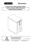
e MODEL: QUANTUM- (Incorporating On/Off switch) Issue 4 09/07/13 DCR 872 INSTALLATION, OPERATION AND SERVICING INSTRUCTIONS Please read these instructions carefully before operating your boiler for the first time Calomax Limited Lupton Avenue, Leeds LS9 7DD Tel. 0113 249 6681 Fax. 0113 235 0358 e-mail: [email protected] www.calomax.co.uk CONTENTS PAGE INTRODUCTION 3 CHECK LIST 3 APPROVALS 3 CONSTRUCTION 4 INSTALLATION 4 LOCATION 4 COLD WATER INLET 5 DIMENSIONS AND WEIGHTS 5 VENT / OVERFLOW 6 ELECTRICAL CONNECTIONS 6 USER INSTRUCTIONS 6 SCALE 7 GENERAL OPERATION 8 GENERAL NOTES 8 CLEANING 8 ACCESSORIES 9/10 SERVICE INSTRUCTIONS 11,14 &15 EXPLODED DIAGRAM 12/13 SPARE PARTS 16/17 WIRING DIAGRAM 18 TROUBLE SHOOTING 19 MAINTENANCE AND SERVICE HISTORY 20/21/22 WARRANTY 23 PRODUCT SPECIFICATION 24 Page 2 INTRODUCTION Thank you for purchasing a Calomax Quantum-e boiler. All our products are designed to give years of simple, reliable operation. To ensure this, it is important that the installation and subsequent servicing is carried out by a suitably qualified engineer in accordance with these instructions. For assistance in finding a suitable engineer in your area, visit our website, contact our service department on 0113 249 6681 or e-mail: [email protected] CHECK LIST Before commencing installation, check that the following parts have been supplied with the boiler: 1. WRAS approved flexible water inlet hose suitable for potable water. 2. 2 keys for keyswitch mechanism 3. BPDTK- plastic / stainless free-standing drip tray APPROVALS This product conforms to the CE marking directive 93/68/ EEC through compliance with the following standards: Electromagnetic Compatibility Directive Low Voltage Directive 73/23/EEC in accordance with: BS EN 60335-2-63:1993 Compliance with these standards has been confirmed through testing by an independent NAMAS approved body Calomax products have been tested and found to comply with the requirements of the Water Supply (Water Fittings) Regulations 1999 for England and Wales Water Bylaws 2000, Scotland and the Water Regulations Ireland. Page 3 CONSTRUCTION All metalic components of the machine, in direct contact with drinking water are manufactured from high quality 304 grade stainless steel, or non ferrous materials, providing maximum resistance to corrosion. INSTALLATION LOCATION 1200 ±100 The boiler must be installed in a location where access is restricted to operators that are suitably trained, or where untrained operators of the machine can be supervised by trained personnel. To comply with recommendations from the health and safety executive it is important that due consideration be given to safe operation of the controls of the boiler. The boiler should therefore be mounted in such a manner that the operator can stand directly facing the machine with the controls at a recommended height from the floor of 1200mm +/- 100mm. Consideration should also be given to the servicing requirements of the machine. The maximum and minimum ambient operating conditions must be between 5 °C and 35 °C. The appliance is not suitable for installation where a water jet could be used. Install the boiler on a surface suitable for near boiling temperatures and the working weight of the boiler. Allow adequate clearance for ventiation and for the easy removal of the outer casing lid and rear panel. Calomax ltd recommend a minimum clearance of 50mm on all sides of the boiler A suitably qualified engineer must install this unit. Plumbing and electrical installation work is involved. Page 4 COLD WATER INLET To comply with the U.K. Water Supply Regulation a single checkvalve must be fitted to the supply. BEFORE CONNECTING, THE SUPPLY PIPE MUST BE THOROUGHLY FLUSHED OUT TO ENSURE THAT FOREIGN MATTER DOES NOT BLOCK OR ENTER THE SOLENOID VALVE The boiler must be connected to a potable water supply using the food grade hose provided, in a manner which complies with UK water regulations. The hose should be connected to a ½” (15mm) drinking water supply via an appropriate isolating valve. The supply must provide a constant pressure of between 20 KPa and 1000 KPa (0.2 to 10 Bar). If the water supply contains excessive solids in suspension it is recommended that a fine mesh “in line” water filter is fitted in the pipe work after the stop cock. Failures due to scale and sediment are not covered by the warranty. DIMENSIONS AND WEIGHTS C B A D MODEL Quantum e mm E A B C D E DRY WEIGHT WORKING WEIGHT 535 240 410 190 65 12 KG 29 KG Page 5 VENT & OVERFLOW The vent / overflow pipe must be extended and laid with a continuous fall, discharging to a safe and visible point. The pipe should not be directly connected to a closed waste, as taste problems may occur and should never be allowed to become blocked or restricted. One way this could be connected is via a tundish arrangement. 15mm copper or ‘Speedfit’ pipe should be used. If the machine is operated without the overfill pipe being extended as advised, any subsequent damage incurred will be the responsibility of the installer. ELECTRICAL CONNECTIONS The boiler is supplied with a fitted plug and lead and should be plugged into a 240v 13A electrical socket, capable of carrying a load of 3kW. The installation of a residual current device (RCD) having a rated residual operating current not exceeding 30 mA is advisable. USER INSTRUCTIONS During normal operation some external parts will become hot. Care must be taken to avoid injury, a burn or scald. Commissioning 1. Turn water supply on 2. Turn electrical supply on On initial switch-on only After a few seconds delay for the electronics to charge up, the boiler will begin filling with water and the ‘Ready’ light will flash to indicate wait. If the key switch is in the ‘on’ position the push button will flash to indicate wait, at this point the button is disabled. When water reaches the low level sensor (element covered) the element will be energised as well as the solenoid. When the selected operating level is reached the solenoid will turn off and the element will remain on until full operating temperature is reached. With the key switch in the ‘ON’ position the push button will stop flashing and show solid colour when the boiler is up to full temperature and the button will be enabled, at this point the ‘ Ready’ light will stop flashing and show solid colour and the ‘Full’ light will also be illuminated. Page 6 On subsequent operation of the boiler The boiler will fill and heat in cycles. It will allow only a limited amount of water to enter the unit at any one time and then switch off the solenoid and energise the element. Note: When the green service indicator light on the front of the boiler is showing solid colour, the machine has been starved of water for in excess of 20 minutes and the solenoid valve has been disabled to prevent damage to the solenoid coil through overheat. To re-energise the solenoid, the unit must be disconnected from the electrical supply and then switched back on, after first reinstating the water supply. Subsequent Use After the boiler has finished the commissioning cycle, and water is drawn from the dispense valve, water will be replaced in short cycles (Small amount of water and then heat) the solenoid and element will never be on at the same time unless the boiler is switched off and on again (Resetting commission mode). In normal use the boiler will always be at operating temperature indicated by the Ready light showing a solid (not flashing) colour. When the boiler is full and ready the Full light will also be illuminated. When the key switch is turned on the dispense button will illuminate with solid colour to indicate water is available. e Energy saving system When the energy saving button is pressed and illuminated, the normal operating capacity of the boiler is reduced from 9 litres to 5 litres, with a subsequent reduction in energy consumption to maintain the lower volume of stored boiling water. This is recommended for use at off-peak periods when demand is low. SCALE The production of scale is a natural phenomenon and commonly occurs in hot water systems. The nature of the scale produced and its rate of formation varies widely throughout the country. To ensure continuous, reliable operation, the boiler should be regularly de-scaled by a suitably qualified engineer. Suitable chemical de-scalants must only be used if the manufacturers recommendations are strictly Page 7 adhered to. This is to prevent health and safety issues, taste problems and potential damage to the appliance. Misuse of such chemicals is not covered by the product warranty. The Quantum-e boiler benefits from an integral scale inhibitor, this is not a scale eliminator and its effects will differ according to the water quality in your area. To ensure trouble free operation, periodically check for scale inside the boiling chamber. The production of scale is a natural phenomenon and some de-scaling may be required within the first 12 months. This is not covered under the products warranty as it is not a fault. If the water supply contains excessive solids in suspension it is recommended that a fine mesh “in line” water filter is fitted in the pipe work after the stop cock. GENERAL OPERATION • hold a cup below the dispense valve or place large vessels on the drip tray. Care must be taken to avoid injury through splashing or over-filling. • To begin filling, enable the dispense valve by turning on the key switch (button will illuminate). Pressing the dispense button will allow water to flow from the valve. • To stop filling, release the dispense button. NEVER PASS YOUR HAND BENEATH THE NOZZLE. GENERAL NOTES • • • Please retain these instructions for future reference Ensure that a suitable drip tray is positioned below the dispense valve. This will help keep the surrounding work surfaces and floor free from drips or splashes. Various options are available and are outlined on the Accessories page of this booklet. All de-scaling and servicing must be performed by a suitably qualified engineer. CLEANING Avoid using any abrasive materials. Wiping the outer casing with a damp cloth should be sufficient. Some stainless steel cleaning products may not be suitable for plastic and must not come in contact with the plastic fascia. Always disconnect the electrical supply before cleaning. NEVER USE A SPRAY JET OR ANY OTHER METHOD WHICH COULD CAUSE WATER TO ENTER THE ELECTRICAL CHAMBER. Page 8 Accessories Worktop-mounting Stainless Steel drip tray Ref. HSSDTK (freestanding) HSSDTWDK (with drain outlet) Boiler securing clamp (To fix boiler to a worktop) Ref. QEC Ingredient caddy Ref. IC3 (3 bay) - as shown IC4 (4 bay) Shelf unit Ref. SHU Page 9 Fused spur time switch Ref. 7DFST Max 3kW Plug-in time switch Ref. 7DPIT Max 3kW Water filter kit (To reduce taste & odour problems) Ref. CWFK Filter Cartridge (Replacement filter for kit shown above) Ref. CWFC1 For more information visit our website at www.calomax.co.uk or call 0113 249 6681 Page 10 SERVICE INSTRUCTIONS If the unit requires servicing the service indicator will flash a sequence of light pulses . A 2x or 3x-light pulse generally indicates that the low or normal level probes require de-scaling. A 4x-light pulse means the water level has reached the high level sensor and the likelihood is that the energy saving or normal level sensor requires de-scaling, or the machine has over-filled due to debris trapped in the solenoid valve. The debris can be removed by drawing plenty of water from the dispense valve, causing the solenoid valve to operate and flush out the obstruction. The machine will reset itself once the problem has cleared. If this does not rectify the problem, turn off the water supply and remove the flexible hose to check for debris in the valve’s filter. The unit can be used normally while the service indicator is flashing a 4x pulse. For further assistance, contact our service department on 0113 249 6681 e-mail [email protected]. or find a local service engineer at www.calomax.co.uk Note: When the green service indicator light on the front of the boiler is showing solid colour, the machine has been starved of water for in excess of 20 minutes and the solenoid valve has been disabled to prevent damage to the solenoid coil through overheat. To re-energise the solenoid, the unit must be disconnected from the electrical supply and then switched back on, after first reinstating the water supply. Once the outer casing is removed, access to the Service Area has been gained. This access must be restricted to persons having knowledge and practical experience of the appliance, in particular as far as safety and hygiene are concerned. De-scale To gain access to internal components, the body lid must be removed. The lid incorporates a condenser mechanism CONTINUED ON PAGE14 Page 11 15 5 3 17 6 18 1 2 2 (Body cut away to show internal components & Outer Casing removed for clarity) 13 If parts required are not iden please contact Calomax Lim Page 12 Exploded parts view for Quantum-e boiler (To be read in conjunction with the spare parts list) 16 8 12 14 10 9 * ntified, mited * 20 11 19 7 * Includes nuts, washers, etc. Page 13 which must be fitted the correct way round. The lid is labelled accordingly. To remove the lid, break the lid gasket seal and pull the lid forward and up, to the front of the machine before lifting it clear of the body. Note: Whenever the body lid has been removed from the boiler a new lid gasket may be required to ensure a steam-tight joint. Damage to the unit caused by a poor lid seal is not covered by warranty. Scale deposits should be removed from all internal surfaces, particularly the heating element, thermistor and level sensors by gently tapping or scraping. If the deposits are soft, use a nylon pad and flush out. Abrasive cleaning materials containing scouring powders and detergents must not be used, such materials can cause taste problems. Suitable chemical de-scalants must only be used in accordance with the manufacturers recommendations. This will prevent health and safety issues, taste problems and potential damage to the appliance. All trace of these chemicals must be removed from the appliance before re-commissioning the unit . Misuse of such chemicals is not covered by the product warranty. IMPORTANT Before re-commissioning the boiler it is important that all scale and moisture is removed from the level sensor insulating gaskets, to avoid a false signal being transmitted through the scale to the boiler body. Failure to remove this scale and/or moisture could cause the sensor to indicate to the PCB that water is covering the element, whether or not water is present. In this situation the PCB could energise the element causing failure. If in doubt, protect the element by hand filling with water to the level of the draw-off tap before switching on the electrical supply to the boiler. General function The printed circuit board (PCB) controls the heating and filling functions of the boiler by monitoring the thermistor and level Page 14 sensors. The PCB also controls the external light unit to indicate the current state of the boiler. Red and yellow LED’S on the circuit board indicate whether the PCB has energised the element or solenoid respectively. The auxiliary PCB controls the dispense valve, push buttons and key switch functions. Should an element fail and need to be replaced, it may be necessary to replace the lid gasket to ensure a reliable steam-tight seal. Note: the element has a permanent ‘Live’ feed, and the ‘Neutral’ is switched. Printed Circuit Board replacement (PCB) In the event of a PCB failing and a replacement being required, full instructions will be supplied. It is important to note however, that the Triac PCB must be securely mounted against the copper heat-sink to ensure reliable heat dissipation. Heat transfer compound is also supplied with all replacement circuit boards. Adjusting the Water Temperature Set Point The temperature potentiometer (Pot) is pre-set at Calomax and will only require adjustment in exceptional circumstances. Contact Calomax for advice. Water boils at different temperatures depending on barometric pressure. The temperature should not be tuned higher than 98°C, or over boiling may occur during low barometric pressure conditions, causing the unit to trip the overheat cut-out device. Page 15 SPARE PARTS (Refer to centre pages for location). 1 2 3 4 QDVMMK DVSK QKM QKK MULLER DISPENSE VALVE & GROMMET DISPENSE VALVE SERVICE KIT KEYSWITCH (INCLUDES 2 KEYS) SPARE KEYS (x2) FOR QKM 5 6 7 EPBK DPBK 8 QPCBT ECO PUSH BUTTON WATER DISPENSE PUSH MAIN PRINTED CIRCUIT Inc. FITTING TOOL BUTTON Inc. FITTING TOOL BOARD Inc. TRIAC 9 10 X1 11 QEAPCBT AUXILIARY PCB 12 NBE3HK TAKE CASSV NB15BLG ELEMENT 3kW THERMISTOR ASSEMBLY KIT SOLENOID VALVE BODY LID GASKET 13 14 15 16 WIH (1m) CASMR QLPK NBPRG WATER INLET HOSE MANUAL RESET THERMAL CUTOUT LEVEL PROBES KIT BODY LID GROMMET Page 16 NB: Not to scale. Spare parts are usually available ex-stock. Please quote Model & Serial Number. 18 17 20 19 QUFK QELFK SVK SPRSK UPPER FASCIA KIT LOWER FASCIA KIT SERVICE VALVE KIT SINGLE POLE ON/OFF SWITCH 21 FIH (1m) IH2M (2m) WATER INLET HOSE NB: Not to scale. Page 17 OPT1 U1 BLUE RED YELLOW ORANGE OP1 BLUE RED YELLOW ORANGE PINK PINK OPT2 SINGLE POLE ISOLATING SWITCH L RED THERMAL CUTOUT E LOWER (YELLOW) PUSH BUTTON ON FRONT PANEL KEYSWITCH ON FRONT PANEL UPPER (GREEN) PUSH BUTTON ON FRONT PANEL N BLACK RED YELLOW / GREEN RED HOT WATER OUTLET DISPENSE VALVE EARTH ON BASE RED YELLOW BLUE BROWN WHITE GREEN BLACK GREY ORANGE BROWN EARTH ON CASING NORMAL HIGH LOW ENERGYSAVING EARTH ON BODY LEVEL SENSORS YELLOW / GREEN PINK BROWN ORANGE WHITE E HEATER LED +12Vdc (BROWN) 0Vdc (ORANGE) N RED ELEMENT BLACK 0.75 white or 0.5mm YELLOW 0.75mm YELLOW BLACK TRIAC PCB COLD WATER INLET SOLENOID VALVE THERMISTOR SOLENOID LED L RED BLACK Wiring Schematic for Calomax Quantum'e' Water Boiler CONNECTOR PLUG Page 18 BASIC TROUBLE SHOOTING Symptoms No boiling water available Thermal cut-out trips regularly Overflows Possible Cause Remedy Selected operating level sensor holding a signal De-scale Thermal cut-out tripped (no light) Reset and check for faults Element failed Replace element Excessive internal scale. (See ‘De-Scale’ page 12) De-scale the boiler (Particularly thermistor) Faulty wiring to thermistors / faulty thermistors Repair / replace as required Temperature controller needs adjusting Lower operating temperature Element failed to earth Replace element Defective Printed Circuit Board Replace Circuit Board Dirt in solenoid valve. Clean solenoid filter / or replace solenoid, “work the boiler” see Service Instructions. Level sensors require descaling or replacing De-scale / replace sensors Printed circuit board faulty Replace P.C.B Page 19 MAINTENANCE AND SERVICE HISTORY Page 20 MAINTENANCE AND SERVICE HISTORY Page 21 MAINTENANCE AND SERVICE HISTORY Page 22 WARRANTY GUARANTEE (UK Mainland customers only) Calomax have manufactured water boilers in the UK for over 50 years. We are proud of our products and the back-up service we provide Properly maintained and serviced, a Calomax boiler should last many years and we have no hesitation in providing a full 12 months (mainland U.K.) parts and labour warranty for all models. Please complete and return the enclosed product registration form as soon as possible to activate this, or register online at www. calomax.co.uk . In addition, the Clipper, Kudos and Quantum models carry an additional 12 month back to base warranty. Some factors are beyond our control and would invalidate the warranty offered. These include: Incorrect installation High / Low water pressure Incorrect voltage supply Accidental damage Limescale build-up The last item can be a particular problem for water dispensing equipment in hard-water areas. All hot water equipment should be serviced and de-scaled by approved organisations on a regular basis to avoid a damaging build-up of limescale. Although our boilers incorporate scale-inhibitor technology, we recommend that a taste, odour and scale filter should be fitted where appropriate. Please visit our website www.calomax.co.uk for details of our Service Partner Network and the range of filters and accessories available Page 23 PLEASE ENTER SERIAL NUMBER FOR FUTURE REFERENCE Model Serial Number Draw off Capacity Heat-up Time (first switch-on) 9 Litre capacity Average flow rate from dispense valve Voltage Power rating QUANTUM- e 9 Litres (5 in energy saving mode) 45 Minutes 2.8 Litres / Minute 220 - 240 V ac 50-60 Hz 3kW (MAX) Note: All measurements are approximate. PLEASE CONTACT OUR SERVICE DEPARTMENT FOR ASSISTANCE Calomax Limited, Lupton Avenue, Leeds LS9 7DD Tel: 0113 249 6681 Fax: 0113 235 0358 e-mail: [email protected] Page 24