1
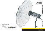
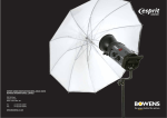
EXPLORER 1500 BWL0355/1
+44 (0)1255 422807
+44 (0)1255 436342
355 Old Road
Clacton on Sea
Essex CO15 3RH UK
Tel:
Fax:
www.bowens.co.uk
EXPLORER 1500
BW7640
USER GUIDE
2
19
Specifications
Maintenance free, non-spillable, sealed Lead Acid Battery
Table Of Contents
Battery Type
Managed Charge Only - 3A Bulk Charge, 0.1A Float
6
Maximum Charge Currents
Only use Bowens recommended charger
Number of Cells
Charger
With supplied 2A Charger (BW-1227) - approx 5-6 hours
With Optional Car Charger (BW-1245) - approx 5-6 hours
Page
Typical Battery Charge Times
(L) 172mm x (W) 108mm x (H) 120mm
Description
Battery Size
4.6KG
12V
Battery Weight
(L) 270mm x (W) 180mm x (H) x 242mm
(H = 281mm inc. handle)
Nominal Battery Cassette
5
Unit Size
11.2KG (with battery)
6.6KG (without battery)
2
Basic Operations
6
Unit Weight
3 x 30A, User replaceable, Automobile Type (ATO Fast Acting)
Introduction
Quick Start Instructions
6
Fuses
Interchangable Battery Cassette
(BW-7642)
12AH
Using the Battery
7
Power Source
50 @ max rate before thermal cut out
Nominal Battery Capacity
Fitting the Battery
7
Typical Flash Rate
AUTO - 0.53 seconds
SLOW - 0.67 seconds
3-4
Removing the Battery
8
12
Recycle Time
(on min power)
with flash heads direct to pack
130 @ 1500Ws
1000 @ 190Ws
1 x BW-3700 Explorer 1500 pack
1 x BW-7642 Battery Cassette
1 x BW-1227 Universal Mains 2A Battery Charger
1 x BW-1821 4m Sync. Lead
1 x BWL-0355 Operating Instructions
1 x Registration Card
1 x Operating Manual
Additional items may be supplied for use in specific countries
Dual Gemini
400 @ 250Ws
260 @ 375Ws
200 @ 500Ws
130 @ 750Ws
Items Supplied
1 x 250W (one head)
2 x 100W (two heads)
Single Gemini
800 @ 250Ws
540 @ 375Ws
400 @ 500Ws
260 @ 750Ws
Typical Flash Capacity
Safety Notes
Charging the Battery
9
10
Basic Controls
Main Menu
Second Menu
12
10-11
Pack Setup Menu
13
Basic Functions Menu
Bracket Mode Menu
13-14
15
Trigger Mode Menu
Load, Save & Restore Menu
17
16
Connecting Flash Heads
17
Auxiliary Control Menu
Flash Power Control
18
16-17
Connecting Esprit Gemini Heads
19
Camera Synchronising
Specifications
Maximum Modelling Lamp
(120V)
18
Connecting Esprit Gemini Monobloc Heads
Two auxiliary outlets, EXTENTION SOCKET 1 and EXTENTION SOCKET 2, are provide d ,
p u r e l y to provide a charging source for up to two Gemini Monoblocs. One or two Gemini’s
can be used on their own or in conjunction with the normal flash heads. The major effect of
using these outlets, in addition to the normal flash heads, is to slow down the overall recycle
time of the pack. Each Gemini controls the charge by itself according to its own setting and
there are NO user controls on the pack for these.
A Travel-Pak cable, BW-7632 as supplied with the
Gemini, is required for each Gemini. DO NOT use
any other type of cable or damage may result.
If only one of the auxiliary outlets is used please
make sure that the dummy socket, attached to the
cable, is fitted to the other extension socket.
Once connected, switch the power on the Gemini(s) to position II. Switch the Explorer on.
The Gemini(s) will now charge followed by the pack. Adjust the flash power on the
Gemini(s) and set up as required. If more than one Gemini is fitted then wait until both are
ready before firing. If the pack is being flashed simultaneously with the Gemini then the
READY indicator on the pack indicates that the overall set-up is READY.
Use is as normal except the Gemini modelling light will not be available.
For correct and safe operation of the Gemini please refer to the relevant instructions.
Dear Valued Customer,
Introduction
Thank you for choosing the Bowens Explorer 1500. The Explorer 1500 has been designed using
the latest technology to produce a unit that is simple to operate, yet has a powerful, highly
controllable and accurate output.
For details of all related products, please contact your local distributor, a list of which can be
found at www.bowens.co.uk
In order to obtain the full benefit from your purchase, please take a few moments to familiarise
yourself with this user guide.
Thank you.
Bowens International Ltd.
•
•
•
•
•
•
•
•
Fully charge every 6-9 weeks to maintain battery condition (if possible leave the battery
cassette on charge indefinately).
Recharge the battery as soon as possible after use. The battery has no so-called memory
effect so for longest life keep fully charged at all times.
Keep the battery cassette clean and dry to prevent contamination of the contacts and fuses.
Do not use any organic solvents or detergents. Wipe with a clean dry cloth.
Take care not to drop the battery cassette - the battery is heavier than its size may suggest.
Use a Bowens approved charger with this unit.
Have the unit checked by an authorised service centre only, due to the high energy/high
voltage of the units.
Have the unit checked out before using if it is dropped or damaged in any way.
Fit only Bowens approved equipment to this unit.
Switch the pack OFF before connecting or disconnecting ANY cables from the pack or
changing a flash tube or bulb on a flash head.
Safety Notes
•
Run skin under water immediately if contact made with electrolyde (acid).
ALWAYS
•
3
4
Safety Notes
•
•
•
•
•
•
•
•
•
Open the battery cassette or try to modify it for any reason. There are no user-serviceable
parts inside.
Move the unit from extremes of temperatures and humidity. When moving the unit from such
conditions allow at least one hour for the unit to stabilise at room temperature before using.
Leave the unit and/or flash heads in close proximity to any flammable materials while the
unit is in use.
Change the fuses for a different type or rating. The Explorer Battery Cassette is protected
by two 40A and one 5A automative blade type fuses. In the event that one or more fuses
have blown it is likely that a genuine fault has occured and the unit and/or battery cassette
will need repair by an authorised service centre.
Open the casing or modify the operation of any Bowens units.
Use a unit with damaged covers, mouldings or sockets.
Charge the Battery Cassette in a gas tight container.
Connect an external mains supply to any Gemini that is also connected to the Explorer (this
may cause a circuit breaker to trip or a fuse to blow).
Leave trailing supply cords and sync leads where they can be tripped over or damaged.
Use the Explorer in an environment where moisture or flammable vapour is likely to come
in contact with the unit.
NEVER
•
Dispose of the battery in normal household waste or in a fire (always dispose of battery in
the correct way. Recycling details below).
The Battery Cassette contains a Sealed Lead Acid Battery containing hazardous chemicals
and it is therefore subject to special waste disposal and/or recycling.
RECYCLING INFO
•
•
In the USA only you may call 1-800-SAV-LEAD (1-800-728-5323) for complete recycling
information.
For disposal information in the UK go to www.wasteonline.org.uk or call G&P Batteries (the
largest nation-wide collector of waste batteries in the UK, particularly lead acid) on
0121 568 3200.
‘Remote Radio Trigger’
Camera Synchronising
The pack has a built-in multi-channel radio receiver compatible with Bowens own Pulsar
radio trigger system and Calumets LiteLink. Enter the PACK SETUP menu and select the
desired CHANNEL number and STUDIO number (if applicable). Then go to the BASIC
FUNCTION menu and set the Radio Sync. to ON. For further details see instructions for
the system used.
Connecting Flash Heads
One or two flash heads may be connected to the pack via sockets A and B.
Always ensure that the pack is switched off before fitting or removing a flash head.
Always ensure that a flash head is removed before carrying out any maintenance to the
head such as changing a flash tube or bulb.
Plug the head in by first inserting the front of the connector into the socket and then
pushing down on the rear to lock it. Always ensure that it is locked before use. To
remove the flash head grasp the conector, not the lead, push the latch away from the
connector and pull it upwards.
Flash Power Control
The pack is designed in such a way that the output to the flash heads can be
continuously controlled in 1/10 f-stops using the Rotary Dial together with the A and B
buttons. The A+B or A/B (SYM/ASYM) selector from the BASIC FUNCTION menu
controls the distribution of power between the A and B sockets.
When set to A+B the overall power of the pack is combined and is available from either
or both A and B sockets. In this mode the A channel controls the overall power and the
LCD shows only the A channel.
When set to A/B the two channels A and B can be controlled separately. At the maximum
power setting there is a fixed ratio of 1 f-stop between channel A and channel B i.e. A =
1000Ws and B = 500Ws.
17
Auxiliary Control Menu
Turn the Rotary Dial to highlight the required
function.
Press SELECT to allow the status or value of
the chosen function to be changed.
Rotate the KNOB to cycle through the
possible settings or values and select the
required one.
‘Auto Off’
This allows the pack auto-off period to be set in the range of 1 - 60 minutes or
NEVER. The pack automatically switches itself off if the cobntrols or Sync. have not
been in use during the selected period.
‘Backlight Mode’
This allows the LCD backlight mode to be set to OFF, ON or AUTO. The display will
be adequate in OFF or AUTO under most working conditions. In AUTO the backlight
will only light if the ambient light is insufficient and a setting changed. It will turn off
shortly afterwards if the controls are not used.
The photocell provides a means of triggering the pack from an external flash source.
Just ensure that the red photocell window on the top panel can ‘see’ the flash source.
Go to the BASIC FUNCTION menu and set the photocell to ‘on’.
‘Photocell’
Two Sync. sockets are provided for a hard-wired triggering system. This allows a
camera to be directly plugged in using the supplied Sync. cable. At the same time a
flash meter or other remote triggering device may also be plugged in to the other
socket. The Sync. cable may be extended using Sync. Extension cords if required.
‘Sync. Cable’
There a number of possible methods of synchronising the pack to the camera or any
other remote triggering device. These can also be used simultaneously allowing
maximum flexibility:
Camera Synchronising
16
Radio Aerial
External
Sync Socket
LCD
Screen
Photocell
READY
L.E.D.
On/Off
Button
Test
Button
A
B
C
D
E
F
G
K
L
M
N
Basic Operations
Auxiliary
Equipment
Sockets
Charge
Socket
Rotary
Selector
Dial
Status
L.E.D.
H
I
J
B Channel/
Select Button
A Channel/
Done Button
Menu
Button
A) Provides the ability to remotely trigger the pack using Bowens Pulsar or Calumets LiteLink.
Remote setting of channels is also provided.
B) Connect a camera, flash meter, remote trigger device etc. via the supplied cable.
C) Displays the current settings and status information.
D) & Backlight Sensor Window - Keep uncovered.
E) Shows green when pack is READY.
F) Press and hold for 2 seconds to turn on. Press again to turn off.
G) Press to flash the pack. It can also be used to quickly dump any excess energy.
H) Allows various menu levels and functions to be selected.
I)
Selects the A channel for control or saves the current selected setting.
J) Selects the B channel for control or selects function for setting.
K) Status LEDs
L) Allows selection of a menu item or adjustment of the currently selected function
or setting.
M) Use the supplied 2A charger if required to charge the battery cassette within the pack.
N) Auxiliary Equipment Sockets - Can power up to two Gemini monoblocs.
5
6
•
•
•
•
•
•
•
•
Select any other option desired.
Select audible READY signal.
Select the required charge rate/recycle time (charge rate can be found in the ‘Pack
Setup’ Menu. Select from either MIN, SLOW, AUTO, or FAST.
Select the required heads and energy level/flash power.
Switch the pack on by pressing and holding the On/Off button for two seconds.
Connect the camera Sync. cord to one of the Sync. sockets or use the internal
photocell or radio for remote triggering.
Connect the required flash heads and/or Gemini monoblocs to the pack. See
operating instructions for these.
A fully charged Battery Cassette can be checked outside of the pack by plugging
the charger into the cassette and switching the charger on. If the indicator on the
charger changes to green within 20 seconds then the battery is at least 90%
charged.
Ensure that a Battery Cassette with sufficient charge remaining for the work
required is fitted into the pack. For best results use a fully charged Battery
Cassette.
Load a previously saved set-up.
‘Load System Setup’
Quick Start Instructions
•
Ensure that the green READY light is lit.
Turn the Rotary Dial to highlight the required
function.
•
Switch the modelling light on if desired.
•
•
•
Use only Bowens approved chargers or permanent damage may occur.
The pack can still be used while charging the battery cassette (providing there is
sufficient charge remaining within the battery).
The pack cannot be used without the battery cassette fitted.
Load, Save & Restore Menu
Press MENU and SELECT together to reset the JOB COUNT.
The pack has two flash counters, PACK TOTAL, which
cannot be modified by the user and JOB COUNT,
which can. The job counter may be used to record the
number of flashes over a particular period by resetting
its value after the session.
This display provides information on the pack history
and current status such as the number of flashes
completed, temperatures, battery voltage, software
version etc.
Status Information Display
Restores all of the factory settings.
‘Restore Setup’
Save the current settings.
‘Save System Setup’
The desired function will be carried out and you will
be left in the SECOND menu.
Press SELECT to initiate the required function.
•
•
The battery cassette can be charged either within or outside the pack from mains
using the supplied charger or alternatively from a vehicle using the optional car
charger.
Using the Battery
•
The battery has no memory effect so it can be charged and discharged from any
state. However, for best results and service life never fully discharge the battery,
charge it as soon as possible after use and keep it fully charged.
15
•
Set ‘SKIP’ to ‘ON’.
Each pack must be connected to the SAME trigger source and must have ‘Skip’ turned on.
This is solely for use with two or more packs and is designed to allow the photographer to trigger
up to eight packs in sequence and therefore enable effectively faster flash rates or to even
produce special effects.
•
•
•
Rotate the toggle botton on the base of the cassette to
realise the two handles and open them fully out.
Lay the battery cassette with the fuses uppermost and the
slotted handle to the right.
Lay the pack on its longest side with the aerial uppermost.
•
•
Slide the battery cassette into the pack with the slotted
handle towards the right. The cassette will not fit in the
pack the wrong way round.
Set Total Packs on each pack to the number in use (2-9).
•
Fitting the Battery
Removal of the cassette is the reverse of fitting.
Gently push the cassette all the way in and fold the
handles down so that they lock the cassette inside the
pack.
•
Lay the pack on its longest side with the aerial uppermost.
Lock the handles in place by rotating the toggle button.
Rotate the toggle button to adjust the lock.
•
Rotate the toggle button on the base of the cassette to release the two handles.
7
Removing the Battery
•
Fold out the handles and pull on them whilst using the thumbs against the pack to eject
the cassette out of the pack.
•
•
Set Shots/Trig to the number required in the range 2 - 99.
•
Stand the pack upright.
Assign each pack a Pack ID according to the order of triggering required. This must be less
than or equal to the total number of packs used.
Once set up and a Sync. signal occurs, each pack begins counting the number of triggers
detected. When this number is equal to the Pack ID of a pack, the pack will then fire.
e.g. Consider 3 packs each set with Total Packs = 3 and individually set with Pack ID = 1, 2
and 3.
Having set SKIP on each pack to ON, the first Sync. signal will cause Pack 1 to fire, the second
(Pack 2) to fire and the third (Pack 3) to fire. The fourth trigger will cause Pack 1 to fire again
and so on.
‘Multi’
•
Set interval to the required time between shots in the range 1 - 99 seconds.
This allows the pack to fire a multiple number of times following a single trigger signal.
•
On receiving a Sync. signal the pack will fire off automatically the chosen number of shots
with the chosen time interval between them.
NOTE:
In setting certain modes the user must ensure that the pack will recharge within the time set,
otherwise it will not be READY and hence will not fire as expected.
•
•
‘Skip’
Trigger Mode Menu
14
8
•
•
•
•
•
•
•
•
•
•
•
Please read the battery cassette safety and maintenance instructions at the end of
these instructions.
A full charge from a discharged state may take anything up to 6 hours depending
on the charger used.
If possible leave the battery cassette to charge for a further 30-60 minutes to
ensure that it is fully charged. The Battery Cassette cannot be overcharged if the
charger is left connected.
When the indicator shows steady green the cassette is approximately 90% - 95%
charged and is being trickle charged.
The green indicator briefly flickering shows the transition between charging and
trickle charge.
In the unlikely event that the indicator shows yellow then there is a fault and the
cassette and charger should be disconnected.
A red indicator on the charger shows that the cassette is charging normally.
Connect the charger to the mains supply and switch on.
If the battery cassette is to be charged outside the pack, plug the charger output
connector into the CHARGE jack socket on the side of the cassette. Avoid knocking
or placing strain on the connector.
If the battery cassette is to be charged inside the pack, plug the charger output
connector into the CHARGE jack socket on the top of the pack.
Choose the adaptor suitable for your mains supply. If an unusual mains outlet is
encountered an appropriate travel adaptor will need to be found.
One universal voltage charger is supplied with the pack and is provided with a set
of mains adaptors suitable for the majority of mains outlets around the world.
Charging the Battery
•
Bracketing allows three consecutive shots to be taken at
power levels above, at and below the current setting level.
The bracketing sequence may be arranged to start at a low
power working upwards or alternatively begin at a high
power and work downwards. First set the desired power
setting.
Set the desired bracket step size between 0.1 and 0.9 by
pressing SELECT to highlight the bracket settings and then
turn the Rotary Dial to set. Press MENU to highlight
START.
Bracket Mode Menu
The unit will automatically check and warn if the selection is not possible within the existing setting
constraints. A warning occurs if the bracket step will take the unit outside of its normal operating
range.
The left most bracket step is always carried out first so ensure that this is negative to start from a
lower power or positive to start from a higher power.
As an example, assume a single head in socket A is set for 6.0. First Select a -0.3 bracket step.
13
Trigger Mode Menu
The screen indicates that the first flash will occur -0.3 stop below the present power setting. The
second flash will be at the present power setting and the final flash will be 0.3 stop above the present
power setting. A pointer under the step indicates the next flash and DONE indicates that the flash is
complete. At any time, pressing DONE will take the user out of bracketing mode.
The three TRIGGER MODES are accessible from the
TRIGGER MODE menu and allow the user to create
delays, multiple flashes and to sequence flashes using
more than one pack.
These modes can also be used in conjunction with one
another. The actual use of these modes is left to the
creativity of the photographer. When they are not
required just leave them switched off. When turning off
the pack all settings within various modes are retained.
‘Delay’
Select ‘DELAY’ and switch on. Press done.
Set time as required between 0 and 9.9 seconds in steps of 0.1 seconds.
Press done..
This allows a timed delay between triggering the pack and the pack firing.
•
•
•
Now there will be the chosen delay between the trigger and the flash occuring.
12
•
•
Turn the Rotary Dial to highlight the required
function.
This allows less frequently used settings to be
changed. From the main menu press the menu
button twice.
Second Menu
•
Basic Controls
In addition to the ON/OFF and TEST buttons the pack functions are simply controlled by means
of three multi-function buttons and a rotary control. In all cases the current status is shown on
the LCD display.
The MENU button selects the next lowest level of the menu.
The backlight automatically switches on if the ambient light level is insufficient for comfortable
viewing.
•
The rotary KNOB highlights menu items or changes values quickly.
Press SELECT to go into the settings menu for
the chosen function.
•
The A and B buttons select the appropriate flash channel for change while in the MAIN
menu.
•
•
The B button also doubles as the SELECT button and selects an item from a menu or
changes the state of a function. e.g. LAMP ON or OFF.
Repeat the above procedure for any other
functions within this menu.
•
The A button also doubles as the DONE button and completes the chosen setting while
repeated presses takes you back up the menu structure.
Pack Setup Menu
This allows the Charge Rate, Lamp Time, Radio Channel and Radio Studio settings to be
altered as desired.
•
•
•
•
•
Turn the pack off by pressing the ON/OFF button and waiting until the splash screen
appears. Release the ON/OFF button.
Releasing the button will cause the MAIN menu to appear and the pack to start charging the
capacitors.
A splash screen similar to that shown will appear while the button is held down, and then
change to the menu display. Release the ON/OFF button.
Turn the pack on by pressing and holding the ON/OFF button.
Turning the pack On & Off
‘Charge Rate’
This determines how quickly the pack will charge and can be
set to AUTO, FAST, SLOW, or MIN.
In all cases the pack will determine the charge state of the
battery and slow down the Charge Rate automatically as the
battery becomes discharged. It is advisable to keep the pack
set to MIN or SLOW whenever a faster charge rate is not
necessary. This will give more flashes from the battery per
charge and also preserves the life of the battery.
‘Lamp Time’
This sets the timeout period for the modelling lamp to be set between 1 to 99 seconds.
‘Radio Channel’
This sets the radio channel (range of 1 - 4, or ALL).
‘Radio Studio’
This sets the studio channel (range of A - F).
9
Main Menu
This is the MAIN or top-level menu shown by
default after switched on:
The top third of the screen shows the flash power
setting for both channels in digital f-stops and
Joules (Watt - second) together with the
functional flash duration in seconds.
To set the flash power press the A or B button to select the required channel. The associated
LED will light to show it is selected. Set the power for that channel by rotating the knob.
Press the appropriate button, A or B again to go back to the MAIN menu where both LEDs will
be off.
The battery CHARGE state is shown in the middle of the screen together with the READY state.
At the bottom of the screen are icons for the most commonly used functions with their current
status. These are controlled by the BASIC FUNCTION menu.
The modelling light is fixed and does not vary with the flash setting. Using the modelling lamp
reduces the number of flashes available from the battery cassette. A 250W lamp switched on
for 10 seconds uses the equivalent energy of between two or three full power flashes. Use a
lower power lamp (50W or 100W) if this is likely to be a problem.
This turns the modelling light on or off. If the modelling lamp is left on it will turn off automatically
after a user-determined period. Set to the desired period from the PACK SETUP menu.
‘Modelling’ (currently selected in picture)
Press SELECT to change the status of the selected
function.
While in the MAIN menu press the MENU button once.
Turn the Rotary Dial to highlight the function icon required.
This is the BASIC FUNCTION menu for selecting and
setting the most commonly used functions.
Basic Functions Menu
10
‘A+B or A/B’
Basic Function Menu
This switches between asymmetric (A/B) and symmetric (A+B) modes. This allows the power
to be asymmetrically split between the two channels A and B, or combined so that the full power
is available from one channel or symmetrically split between them.
‘Radio’
This turns the multi-channel radio receiver on or off. This is compatible with Bowens own Pulsar
Radio Trigger system and Calumets LiteLink. Select the desired Channel and Studio numbers
from the PACK SETUP menu. For further details see the instructions for the system used.
‘Sounder’
•
A short beep for button presses.
A short beep when the pack comes to READY.
This switches the sounder on or off, which when switched on provides the following:
•
‘Photocell’
This switches the sensitive photocell on or off and provides a means of triggering the pack from
an external flash source. Always ensure the red photocell window on the top panel can ‘see’
the flash source.
11