1
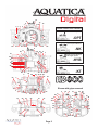
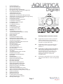
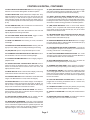
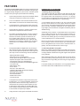
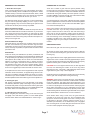
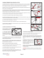
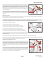
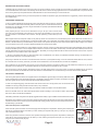
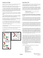
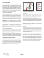
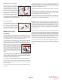
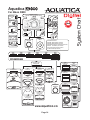
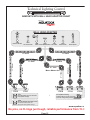
FOREWORD
Thank you for having selected the AQUATICA Digital Camera Housing System for your underwater photography.
The AQUATICA AD7000 Digital Housing is the result of a long and continuing relationship with the most demanding underwater photographers in the world. Each housing is machined from solid aluminum on the best 5 axis computerized machine for the highest level
precision, it is then hand finished, quality checked and pressure tested to a 90 meters/300 feet equivalent by a small group of specially
trained individuals, each of whom takes the utmost pride and satisfaction in offering the best underwater camera housing in the world.
The Aquatica Digital Housing was designed for optimum technical and optical performance and to provide easy and efficient underwater
access to essentials functions and controls of the Nikon D7000 DSLR.
This manual assumes that the user is already familiar with the Nikon D7000 camera. If not, please read the Nikon instruction manual
before attempting to use the housing.
With basic care and maintenance, your AQUATICA housing will give you a lifetime of enjoyment and satisfaction in producing underwater
images.
Please read this manual carefully before using your housing for the first time and note that: wherever cited the right hand is your right
when using the housing.
SAFETY PRECAUTIONS:
Improper transportation handling or use of this housing might cause a flood or malfunction.
Please read and follow the following precautions:
•
Store and transport the housing in a sturdy, shock proof container and avoid travelling with the camera mounted
inside the housing as impact forces especially on the external push buttons will be transferred to the camera.
•
When travelling by air, either remove the port or open the housing, internal pressure built up can push port out of
their sealing surface.
•
Never change a port or open the housing in a location where sand or similar foreign material might come in
contact with an O-ring.
•
Use of accessories, modifications or alterations unauthorized by the manufacturer may result in flooding or poor
functioning of the controls.
•
Be careful when opening the housing as possible pressure buildup inside the housing could exaggerate the force
of the latch spring. Keep fingers away from the path of the latches.
•
Whenever changing ports or O-rings, perform a simple seal test without the camera inside.
•
Take extra care to avoid scratching the acrylic, glass ports and windows, handle theses as you would your camera
lenses.
•
Make sure that all ports remain properly attached before rinsing the housing, especially when rinsing without a
strobe make sure the wired bulkheads connectors, if you are using this type of connectors are sealed with their
supplied plug. (Optical type connectors are water proofed)
•
Never attempt to operate the camera in autofocus mode with standard (NON AF-S type) lens which have a mounted focus gear engaged with the housing focusing gear mechanism.
•
The main O-ring seal should be maintained and cleaned on a regular basis. Read and follow the Care and
Maintenance section on this manual.
•
Ensure that the spring loaded secondary lock is properly engaged on the latches to prevent their accidental opening.
Page 1
6
4
3 1
7
8
10
9
13
14
11 12
STROBE CONNECTORS VARIANTS
Dual optical
2
15
17
5
22
19
26
27
48
47
16
18
21
25
-OPT
20
23
24
Dual 5 pins Nikonos
22
-NK
8
11
28 29
6 30 4 3
46
45
44
43
42
41
40
39
Single 5 Pins Nikonos
and single optical
-HYB
31
2
38 37
28
8
55
48
45
3
Single 5 Pins Ikelite
-KT
32
36 35 34 33
49 50 52
51 47
55
31
4
2
Shown with grips removed
1
6 53
57
7
57
59
9
10
54
56
11
12
57
13
57
14
29
30
3
28
8
4
53
9
7 11
6
12
14
1
31
2
60
61
5
16
18
20
58
57
58
10
57
62
Page 2
27 23
62
52
50
51
49
47
46
60
61
1-
2-
3-
4-
5-
6-
7-
8-
9-
10-
11-
12-
13-
14-
15-
16-
17-
18-
19-
20-
21-
22-
23-
24-
25-
26-
27-
28-
29-
30-
31-
32-
33-
34-
35-
36-
37- 38-
39-
40-
41-
42-
43-
44-
45-
46-
47-
48-
49-
50-
51-
52-
53-
54-
55-
56-
57-
58-
59-
60-
61-
62-
Shutter Release lever
Sub-Command Dial knob
Main Command Dial knob
Movie Record button actuating lever
DoF (Depth of Field)) & Fn (Function) toggle lever
Power Switch/Illuminator lever
Top Bulkhead access hole
Internal Flash lowering lever
Optical strobe connector (Sea & Sea type shown)
Optical strobe connector (Inon straight cord type shown)
Flash Mode & Compensation lever
Internal Flash up button
Focus/Zoom pinion gear release disk
Focus/Zoom Control knob
Focus/Zoom Control pinion gear
Lens Release knob
Lens Release knob lever
AF/MF selector
Focus Mode Selector fork
AF mode selector button
AF mode selector actuator
Grips (x2)
Front Bulkhead access hole*
* (shown with optional Hydrophone installed)
Camera mounting screw
Quick release tray
Bayonet Flange
Port Release mechanism Lever
Metering Pattern Selector button
AE-L/AF-L & AF-ON lever Rotating collar
AE-L/AF-L & AF-ON lever
Exposure Compensation button access lever
Multi Selector center button
Multi selector array
Live View actuating button
INFO activation button
Live View mode selector lever
Rear LCD window
Moisture Alarm LED receptacle
(OK) Button
Thumbnails/Playback Zoom out button
Playback Zoom in button
Protect/Picture Control/Help Button
Menu button
Playback button
Delete button/Format button
Release mode dial selector knob
ISO button access lever
Removable Viewfinder
(BKT) Exposure Bracketing button
(QUAL) Image Quality access button
(WB) White Balance access button
Release mode selector unlock button
Exposure mode selector
Top accessory mounting hole (1/4”-20)
Grip’s Accessories mounting holes (1/4”-20)
Bottom accessories mounting holes (1/4”-20) (x3)
Rubber Anti Skid pad
Sacrificial Anodes (x1)
Bulkhead access hole
Locking Latches (one per side)
Safety locking tab (one per latches)
Mounting holes for grips
Page 3
Housings strobes connection variants:
-OPT
Supplied with two optical connections. Included are
adapter for attaching two Inon type (straight tip)
sync cords or two Sea & Sea type sync cords. S-TTL
is possible if using appropriate strobes
-NK
Supplied with two Nikonos Type connectors. TTL is
possible if using a TTL converter with compatible
strobes for it.
-HYB
Supplied with one optical connector and one Nikonos
type connector. Included are adapter for attaching two
Inon type (straight tip) optical sync cords or one
Sea & Sea optical type sync cords. Optical S-TTL is
possible if using appropriate strobes as well as
standard TTL if using a TTL converter with
compatible strobes
-KT
Provided with a single Ikelite connector. TTL is possible
if using the # 4301 Ikelite TTL converter and appropriate
strobes
CONTROLS IN DETAIL
1- SHUTTER RELEASE LEVER: Pulling the shutter release lever
back part way activates the camera meter and auto focus. Pulling
the lever back all the way fires the camera.
2- SUB-COMMAND INPUT / APERTURE KNOB: Rotates clockwise
and counterclockwise. Use alone or in combination with other controls
to select or set various camera functions or modes. In “Manual” the
exposure mode controls the aperture settings (see shooting tip).
3- MAIN-COMMAND INPUT KNOB: It rotates clockwise and counterclockwise. It can be used alone or in combination with other controls to select or set various camera functions or modes. Refer to
camera manual for in depth use (see shooting tip #3 & #4).
4- MOVIE RECORD BUTTON ACTUATING LEVER: Pull to start
recording video, pull again to stop, works in conjunction with Live
View mode selector (key #36).
5- (DoF) Depth Of Field & (FN) Function toggle lever: Toggles to
engages these buttons, these camera buttons are highly customizable
for both still and video features.
6- POWER SWITCH KNOB: Rotate to switch camera on or off.
7- TOP BULKHEAD ACCESS HOLE: A standard ½” plugged hole
for receiving accessories such as a remote cord or other wired
accessory.
8- INTERNAL FLASH LOWERING LEVER: Push to close internal
flash of the camera, used with either –OPT or –HYB type of housing
9- OPTICAL STROBE CONNECTOR: For connecting optical cord
from strobe (Sea & Sea type shown, other option available, see
strobe connectors section for more details).
16- LENS RELEASE LEVER: activates the lens release button on
the camera allowing easy removal of the lens.
17- LENS RELEASE INTERNAL KNOB LEVER: Applies pressure
on the camera lens lock button
18- AF/M SELECTOR KNOB: rotate to select between auto or
manual focus
19- FOCUS MODE SELECTOR FORK: Engages the focus AF/M
selector of the camera.
20- FOCUS MODE SELECTOR BUTTON: Press to select between
AF-A, AF-C and AF-S or for 3D, Auto, single or multiple point
focusing. Use main command or sub command knob to choose
options.
21- FOCUS MODE SELECTOR ACTUATOR: Presses on the AF
Mode button of the camera.
22- HAND GRIPS (X2): Left and right grip allowing the mounting of
strobe arms and accessories.
23- FRONT BULKHEAD ACCESS HOLE: Standard ½” hole for
mounting accessories such as optional Hydrophone (shown) or
other wired accessories.
24- CAMERA MOUNTING SCREW: Used to attach camera to
quick release tray.
25- REMOVABLE CAMERA TRAY: Holds camera in place and
slide in housing, allowing easy battery replacement.
10- OPTICAL STROBE CONNECTOR: For connecting optical cord
from strobe (Inon type shown, other option available, see strobe
connectors section for more detail).
26- BAYONNET MOUNTING FLANGE: Allows the mounting of
different ports and extension rings on the housing.
27- PORT RELEASE MECHANISM LEVER: pull to release the
locking mechanism when installing or removing a port or extension.
11- FLASH MODE & EXPOSURE COMPENSATION LEVER:
Press to engage the flash exposure compensation or flash
synchronization mode, use main or sub command knob to select
options. (see also shooting tips)
28- METERING PATTERN SELECTOR KNOB: Push to select
the metering mode by rotating the main command dial (key #3),
options are: Spot, Center Weighted or Matrix metering (see also
shooting tips #5).
12- INTERNAL FLASH UP BUTTON: push to get the internal flash
of the camera in up position (used with –HYB and -OPT type of
housing
29- AE-L/AF-L & AF-ON LEVER ROTATING COLLAR: Pull out
the AE-L/AF-L Lever and rotate this collar to position it in the
desired mode.
13- FOCUS/ZOOM PINION GEAR RELEASE DISC: A release
disk is provided to disengage the knob should you want to us a non
AF-S lens in autofocus or when you wish to remove the camera,
with lens attached, from the housing.
30- AE / AF & AF-ON LOCK LEVER: Lock the auto focus / auto
exposure or use for activating the AF-ON button according to
preference
14- FOCUS/ZOOM KNOB: Turning allows manual focus of a single
focus lens or rotation of the zoom mechanism of a lens.
15- FOCUS/ZOOM PINION GEAR: Engages and operates the
focus or zoom gear attached to the lens.
31- EXPOSURE COMPENSATION BUTTON ACCESS LEVER:
Pull to engage the Exposure compensation control [+/-]. Rotate
the Main-Command knob to set the desired exposure compensation value. The value will appear on the rear LCD panel and in
the Viewfinder. This button when pressed along with QUAL (key #
50) button will reset the camera shooting parameter to its default
position.
Page 4
CONTROLS IN DETAIL, CONTINUED
32- MULTI SELECTOR CENTER BUTTON: Press to engage the
selection or use Custom Setting Menu for different options.
33- MULTI SELECTOR: These buttons have multiple uses. They
allow the selection of the focus area, in the menu mode, they are
used to scroll up or down and left to right to choose from your
menu selection and they are used as well in the delete mode. To
accept a selection press the center button (#32) or the OK button
(# 39).
34- LIVE VIEW BUTTON: push to activate the Live View function
of the cam era (required for video mode).
35- INFO BUTTON: This button will activate the rear LCD and
display all pertinent shooting information.
36- LIVE VIEW MODE SELECTOR LEVER: Toggle to select
between the LIVE VIEW mode for still or movie.
37- REAR LCD WINDOW: allow viewing of menus, information
and images.
38- MOISTURE ALARM WARNING DIODE: Warning LED will
light up in the unlikely event of water penetrating the housing.
39- (OK) BUTTON: push to accept selected option or menu.
40- THUMBNAILS/PLAYBACK ZOOM OUT BUTTON: Push to
see thumbnails or to zoom out when reviewing images.
41- PLAYBACK ZOOM IN BUTTON: Push to magnify images in
playback mode.
42- PROTECT/PICTURE CONTROL/HELP BUTTON: Push to
protect an image in playback mode, in shooting mode it gives
access to the Picture Control function and in the menu, will
display the HELP screen.
43- MENU BUTTON: Press to activate menu display, scroll using
multie selector buttons and select using OK button.
44- PLAYBACK BUTTON: Press to activate the monitor and review
images. Use Multi Selector to scroll, select and magnify.
45- DELETE BUTTON: Press to delete images, use multiple selector buttons to select and press the enter button to delete, can
also be used in conjunction with the mode selector button (Key
#53) in order to format the card inside the camera.
46- RELEASE MODE DIAL SELECTOR KNOB: This knob rotate the release mode dial. To rotate the dial, the locking button
(key # 52) must be pressed down.
47- ISO BUTTON ACCESS LEVER: Pull to engage the ISO
button, select ISO using the Main Command knob (#3) (
49- (BKT) EXPOSURE BRACKETING BUTTON: Press to engage
and select bracketing exposure parameter using either or both
the main command (#3) and sub-command knob (# 2)
50- (QUAL) QUALITY/SIZE & RESET BUTTON: Press to
access the different image quality available on the camera; use
in conjunction with main and/or sub command dial control knobs.
Pressing this button and the Exposure compensation (#31) lever
will reset the camera shooting parameter to its default position.
51- (WB) WHITE BALANCE: Press to access white balance
functions, use in conjunction with subcommand dial (Key #3) to
select mode and/or main dial controls (Key # 2) to the select
attributes of the selected mode.
52- RELEASE MODE DIAL SELECTOR UNLOCK BUTTON:
This button unlock the release mode dial so it can be rotated,
with the release mode dial knob (# 46)
53- EXPOSURE MODE SELECTOR BUTTON: Push to engage
the mode selector button, rotate the Main Command knob (# 3)
to select the desired exposure mode.
54- TOP MOUNTING HOLE FOR ACCESSORY: a 1/4”-20 TPI
hole is supplied to accept a TLC accessory or TLC base ball for
mounting a strobe arm or a modeling light.
55- GRIP’S ACCESSORIES MOUNTING HOLES: Two 1/4-20
TPI holes on each grip are ready to accept TLC Base Brackets or
TLC Base Ball for strobe arms or accessories.
56- BOTTOM MOUNTING HOLES: Three 1/4” X 20 holes are
provided for mounting strobes trays or accessories.
57- RUBBER ANTI SKID PADS: rubber pads are provided to
protect the housing and preventing it from sliding on wet decks.
58- SACRIFICIAL ANODE: A zinc anodes is installed to protect
your housing against salt water corrosion; it is made to deteriorate
faster than the other strategic metal part of your housing, hence
the name sacrificial anodes. This anode need to be replaced by
the user as needed.
59- BOTTOM BULKHEAD ACCESS HOLE: A standard ½”
plugged hole for receiving accessories such as a remote cord,
monitor or other wired accessory.
60- LOCKING LATCHES: Two heavy duty latches (one per side)
with safety locks to protect against accidental opening.
61- SAFETY LOCKING TAB: Push safety tab and lift latches to
open.
62- MOUNTING HOLES FOR GRIPS: Threaded 5/16” holes for
mounting grips (see care and maintenance section)
48- REMOVABLE VIEWFINDER: A full view of the illuminated
camera viewfinder displays all necessary information. This viewfinder
can be removed and replaced with the optional Aqua View 180
Finder (# 20054) or Aqua View 45 Finder (# 20059) for a larger
displayed image or more comfortable shooting position.
Page 5
FEATURES
The Aquatica Digital AD800 Digital Pro housing is issued from the
world’s most technologically advanced underwater housing lineage,
it is ergonomically designed to place all the essential camera
controls under your finger tips and features the following:
A.
A port locking mechanism to prevent accidental rotation
of the port or extension mounted on the housing
B. A Lens Lock Release control that will activate the lens
release button of camera from the outside of the housing.
C. A quick release tray, allowing fast and easy removal of
camera with lens and gear attached to the camera body.
D. Large ergonomic and easy to operate controls for the
manual and computerized camera functions.
E.
The industry most flexible strobes connector selection;
options includes standard Nikonos, Classic Ikelite
electrical connections, optical connections for the
Inon and Sea & Sea optical sync cord. An internal
switchboard allows full manual or TTL exposure with
electrical sync cord when a compliant TTL converter is
attached; S-TTL is available when using the proper
strobes
F. The Aquatica AD800 Pro Digital is the only housing to
offer exclusive access to all controls and buttons found
on the camera. Special emphasis was made to give the
user easy access to the following controls underwater:
- Mechanical shutter release.
- Movie Record via a dedicated lever
- Shutter speed through the Main-Command Dial
- Aperture through the Sub-Command Dial
- ISO sensitivity value via a dedicated lever
- Fn & Depth of Field buttons via a dedicated toggle lever
- Live View mode
- Multi Selector array
- Focus / Zoom
- AE-L/AF-L & AF-ON access
- LCD panel illumination & information display.
- Metering pattern selector
- Exposures Compensation
- Focus Area Selector
- Delete button access
- Live view access
G. A comprehensive selection of bayonet mounted ports
including the 4”, 6”, 8” and 9.25 diameter domes, three
flat ports and various extension rings. These are of
manufactured from the finest optical material in order
to preserve the image quality of your Nikon Mount AF
lenses. Adapter rings also allows other brands of ports
to be used with an Aquatica port adapter.
H. A large selection of lens gears and related accessories.
PREPARATION OF THE HOUSING
1. Attaching Grip to the housing:
The housing comes with two Grips for both right and left hand
grips which should be installed on the sides of the housing with
the supplied bolts and hexagonal key wrench. It is strongly
recommended to occasionally remove the grips and lubricate the
screws (see Care and Maintenance: of the housing.)
¼”-20 threaded holes are located on the top of the hand grips
(# 55) to accept bracket for most popular strobe arm system
you are using. The Technical Lighting System strobe arm system
which has been developed exclusively for the Aquatica housings is highly recommended as it integrates seamlessly with the
AD800 housing.
Additionally, there are three ¼”-20 threaded holes on the bottom
of the housing (# 56) that can be used for various mounting application including a tripod. And a ¼”-20 threaded hole on the top
rear half of the housing (# 54) for mounting accessories such as
a focus assist light or TTL converter bracket.
Mount your strobe arm on the housing and connect the sync cord
to the housing’s strobe connectors as per your strobe manufacturer. If using eletrical sync cord, be sure to read the section regarding the care and maintenance of the O-rings.
2. Lubricating the Main O-ring Seal:
Before use, carefully inspect the Main O-ring seal in the groove on
the front half of the housing to confirm that it is free from scratches
or foreign material. Lubricate the O-ring with a light coat of Aquatica
O-ring lubricant.
When replacing a Main O-ring, first place this one over the O-ring
groove and start by pushing the O-ring in the corners. Work your
way around the O-ring making sure the O-ring is snugly sitting in
the groove.
For proper handling and maintenance of O-rings please refer to
the section titled “Care and Maintenance: of the O-rings.”
Page 6
PREPARATION OF THE PORTS
PREPARATION OF THE LENS
1. Select the correct port:
Once you have decided on the type of photography for the dive,
you will be installing either a flat Macro Port (product # 18426,
18428 or 18429), or a Dome Port (Product # 18405, 18407, 18409
or 18410). Refer to the Nikon Type 4 lens chart for the suggested
port and accessories required for the lens you choose.
There are a number of gear and lens options possible. Using
the right gear and correctly mounting it on the lens is primordial
for a smooth housing operation. Follow the installation directions
included with each gears carefully. Since the aperture control on
the Nikon D800® is achieved through the Sub-Command Dial,
the use of AF types of lenses is mandatory.
Port Extension Rings serve two purposes, in macro photography
they are used for physically adapting a lens to a port, in wide
angle photography they are used for matching the optical center
of both lens and dome port as closely as possible.
A comprehensive list of the lenses supported and their required
gears is supplied at the end of this manual. For the latest updated
version of this lens chart, you can refer to the latest Nikon Type 4
Lens Chart at www.aquatica.ca
Macro Port Extension Rings:
Both the Macro Ports 18426 and 18428 will accept the AF-D &
AF-S Micro-Nikkor 60mm lens without extension. If you intend to
use a longer lens such as the 105mm you will require an additional extension ring. These extension rings are inserted between
the Macro Port and the housing and provide the extra space necessary for the longer lens.
Notes: If the camera is set in manual focus a focus gear must be
mounted on the lens. If you are using a zoom lens with a zoom
ring the camera must be on auto focus, also note that if using a
dome port you may be required to install a close up diopter on
the lens to correct the minimum focusing distance of the lens so
that close focusing on the virtual image created by the dome is
possible. The Nikon Type 4 lens chart will inform you if of the
suggested diopter for your lens/port combination and if one is
needed.
Dome Port Extension Rings:
With wide angle or most zoom lens, the Dome Port may require
the uses of an extension ring. These extension rings are inserted between the dome port and the housing and are intended to
match, as closely as possible, the optical center of both the dome
port and the lens.
Dome Shade:
Of the four dome port available, the (# 18410) 4” Minidome and
the (# 18407) 9.25” Megadome are provided with the shades built
in, the (# 18409) 6” & (# 18405) 8” acrylic dome port have removable optional dome shade, this two dome are recommended if
planning on using a circular fisheye lens, in regular use and in
order to reduce glare, maximize the contrast and offer a physical protection to the dome, the use of a dome shade and its
neoprene cover is highly recommended. Refer to the AD800 lens
chart for the suggested port and accessories for the lens used.
A comprehensive list of the lenses supported and their required
extensions and/or accessories, is supplied along with this manual. Due to constantly changing selection of lenses, it is recommended that you visit our website on occasion to have access to
the latest updated version of the Nikon Type 4 at www.aquatica.ca
2. Cleaning the port:
Dirt, grease or fingerprints on the port especially on the inside,
can adversely affect the quality of the image. Acrylic ports should
be cleaned with plastic or acrylic safe cleaner and the glass ports
should be cleaned with lens cleaner. For more details please read
the section titled “Care and Maintenance: of the Ports.”
3. Lubricating the port O-ring seal:
Before using the port, remove the O-ring on the rear of the port
and lightly coat it with silicone grease. For more details please
read the section titled “Care and Maintenance: of the O-rings.”
GEAR INSTALLATION:
Mount the focus gear over the focus ring of the lens.
(a) For Slip-on gears (gears without mounting screws): Slide the
gear over the lens and align the gear with the front of the lens
focusing ring.
(b) For gears with set screws: Lightly tighten the set screws evenly.
Tighten each screw in small increments (approximately a quarter
turn each) working around the gear until all the screws are properly
tightened and the gear is concentric with the lens body.
CAUTION: Do not over-tighten these screws, as this might bind
the lens, thus restricting the rotation of the focus ring and/or
damaging the lens. Conversely under-tightening these screws
might cause the gear to slip or loose alignment.
Rotate the focus ring several times to make sure it moves smoothly
and the gear does not slip before closing the housing
WARNING: If the lens is a not of the AF-S type, never attempt to
operate it with the camera in autofocus mode and with a mounted
focus gear engaged. This might cause serious damage to your
camera or to the lens. With standard AF lenses switch from manual
to auto focus by lifting the focus knob and the under laying disc
(#13) rotate and position it so as to disengage the focus gear
mechanism, then switch the AF/M lever (# 18) to AF position. Also
avoid travelling with the zoom/focus gear attached as any impact
will be directed at the sensitive zoom or focus mechanism
Zoom lenses: When using a zoom lens, the gear should be
mounted on the zoom ring of the lens. The Focus/Zoom knob
(#14) then control the zoom gears on the lens. Focusing of lens
is achieved by using the camera’s autofocus system or by a
dedicated port extension, the # 18426 Macro port is equipped
with a focusing knob on its side that gives manual focus access
to macro lenses equipped with the proper gear.
Page 7
CAMERA PREPARATION AND INSTALLATION
1- Important Note: prior to installing the camera in the housing, remove the rear LCD plastic
protector from the camera as well as the camera strap, Clips and/or any object that might obstruct installation, third party camera strap hookup should be removed or tucked away
24
A
2- Make sure the ON / OFF /ILLUMINATOR knob (# 6) is in the ON position and that the lens lock
lever (# 16) is in the proper position
25
B
3- Remove the quick release tray (key # 25) from the housing by pressing down the metal tab
(A) and pulling the tray out (B). Carefully place the camera on it, making sure that the camera is
properly aligned and secured against rotation or movement.
4- Align the Tripod Socket of the camera with the mounting screw (key # 24). Tighten the mounting
screw securely while ensuring that the camera position is not altered.
5- Pull out the lens release lever (#16) and the AF/M knob (# 18) clear
6- Position the AF/M lever (# 18) on the side of the camera to M (as per illustration at right) and
align the fork of the AF/M actuator (# 19) accordingly..
DoF & Fn
toggle
actuator
25
24
“M” position
NORMAL ACTIVE
7- If using the optional Hydrophone connect the plug to the camera audio jack, and tuck the rubber
flap of the microphone plug safely out of the way.
8- Slide the quick release tray (key # 25) back into place, it will lock itself into place.
9- Test the DoF & Fn toggle (# 5) and the AF/M lever (# 18) to confirm that they are properly
aligned and working smoothly.
16
17
18
CLOSING PROCEDURE OF THE HOUSING
19
Once the camera is secure
on the saddle inside the front
half of the housing, simply:
1- If using wired connection
for the strobes, slide the
housing’s hot shoe connector
onto the hot shoe base of the
camera as seen in drawing
at right.
To close the housing simply:
a) Join the front and rear halves of the housing using the two
dowel pins at the bottom of the housing as a guide.
2- If using optical connectors, make sure your built in flash on the
camera is free of obstruction and can go up. Confirm its operation
before immersing the housing.
With the -HYB version, if using optical, then do not install the hot
shoe as this will cancel the built in flash of the camera and prevent
the built in flash from coming up.
Before closing the housing always confirm that:
1- The main O-ring on the front half of the housing is clean,
lubricated and properly seated for a positive seal.
2- The sealing surface on the rear half of the housing is clean and
free from any scratches or physical damage.
3- All cords, wires and the rubber flap of the microphone cover
are tucked in such a way as to prevent interference with the
closing of the housing and its sealing integrity.
b) Hold the housing with both hands and look around the sealing
surface to ensure that the O-ring is properly seated and that no
cords, wires, rubber cover or “D-rings” are caught between the
edges.
c) Close the two side latches (# 60)
simultaneously and verify that the
locking tab is engaged. To open
reverse the process, push on the
locking tab and lift the latches being
careful of your fingers.
61
60
d)Always verify that the safety locking mechanisms (# 61) of the
latches are properly engaged prior to entering water to avoid any
accidental opening.
CAUTION: if you feel any resistance as you attempt to close the
latches, do not force the closure. Check for any obstructions and
try again.
Page 8
LENS INSTALLATION
With the camera inside the housing, first disengage the pinion gear (#15) by pulling and
rotating the disc (# 13) under the focus/zoom knob into the up position, install the lens
prepared with its gears through the port opening in the front of the housing. If using a gear
always confirms that it is properly installed and aligned on the lens. Once installed,
release the disc (key # 10) and rotate the focus / zoom control knob (Key # 14) to
ensure that the gears are properly meshed, that their rotation is smooth and that it does
not do not grind or bind.
Note: To avoid damaging the auto-focus mechanism of the camera when using standard AF-D type lenses, you should always set the Focus Control to “M” Manual for testing the proper meshing of focusing gears. This procedure is not required with AF-S
type lenses.
14
15
13
Resting Pins
MOUNTING THE PORT
Before mounting the port on the housing always ensure that the port O-ring is clean, lubricated and properly seated in its groove and that
he sealing surface on the housing is clean and free of physical damage.
The AQUATICA AD7000 Digital Housing System features a bayonet mount (# 26) equipped with a locking mechanism (# 27). If there is
already a port or extension mounted on the housing and you wish to remove it, simply pull the lock lever (# 27) until it stop, rotate the port
counter clockwise and carefully pull out, and put it aside in a safe place with the port lens delicate surface protected.
To mount the port or extension ring simply:
1- Place the housing on its back on a soft steady surface.
2- Place the port or extension ring inside the main port of the housing.
Align one of the four alignment notches with the opening of the housing.
3- Place your hands on opposite sides of the port or extension ring.
27
TO UNLOCK
UNLOCK
4- Push with even force on both sides of the port or extension ring until you
feel it snap into place. Make sure the bayonet is completely inside the housing.
LOCK
26
5- Turn the port clockwise until it stops. Do not force, if there is too much resistance
takes the port off, check the O-ring and retry. the port lock will engage itself once it has
completed its rotation.
6. confirm visually the proper seating and sealing of the port or extension and that it is safely locked on the housing.
Note: It is recommended that you familiarize yourself with this mount by trying it without the camera; this will allows you to see the inside
view of the bayonet mount and of the ports or extension rings in the housing.
CHANGING A LENS (REMOVING A LENS)
From the front: Remove the port; the lens mounted gears may restrict the view and
ease of access to the lens release button of camera. The AQUATICA AD800 Pro Digital
Housing features a Lens Release Lever (key # 16) that is designed to trigger the lens
release button of camera to allow easy removal of lens. To remove a lens, simply rotate
Lens Release Lever (key # 16) to press the camera lens release, hold and turn the lens
clockwise.
From the rear: remove the back, pull out the lens release lever (# 16) and the AF/M knob
(# 18) out of the way. Lift and turn the disc under the focus/zoom knob (# 14) so that
it come down on the resting pin, this will disengage the pinion gear ( #15), release the
saddle lock, remove hot shoe cable if using one and pull out the camera and lens assembly, replace lens and reinstall by reversing this procedure.
Page 9
14
15
Resting Pins
13
16
18
MOUNTING AND ATTACHING FLASHES
Threaded holes are provided on top of the hand grips to accept the necessary shoes or bracket to accommodate your strobes arms. Additionally, three
1/4”-20 threaded holes on the bottom of the housing can also be used for various mounting applications and a 1/4”-20 threaded hole on top of the rear half
of the housing will accept an Aquatica bracket or Base Ball that can hold a focus/video light or a extra strobe arm.
Developed with the Aquatica housing in mind, the Aquatica TLC Strobe Arm System is highly recommended for its ruggedness, precision and the quality
of its craftsmanship.
USING WIRED CONNECTORS
If using an Aquatica AD800 Pro Digital housing setup with electrical strobe connections, these will
be connected to a switch board circuit that gives the users the option to choose between full manual
exposure or TTL (an external converter or single housed flash is required). Optional Ikelite bulkheads
connectors are also available.
When preparing the sync cord, be sure to lubricate the O-ring on the sync cord’s connector with a
light coat of the recommended O-ring lubricant for your strobe, Also advisable is to put a light coat
of O-ring lubricant on the threads of the connector, this help preventing corrosion built up on the
threads
ON
1
ON
GTS
2
3
OFF
4
Nikon Digital cameras are setup with a flash circuitry that only allows one iTTL flash to be connected directly to the camera, Nikon will not allow two TTL
flashes to be electrically connected directly, no matter if it is a Nikon flash or any other brand. The wireless approach preferred by Nikon prevents additional
flashes, or strobes from being connected directly to the camera, iTTL exposure will stop to function and a camera freeze is likely to happen. Two strobes
can be connected only if a TTL converter is interfaced between the camera and the strobe.
On your housing you will find either one or two bulkhead connectors, the main connector (on right side) is wired through a switch board that can be configured
for full manual flash exposure or to be compliant with the latest TTL converter on the market. The secondary connector (left side if installed) is wired in a full
manual configuration and cannot be used for iTTL operation. By default you housing is delivered with the switch board set to full manual, if iTTL exposure
is desired then it can be made in either of two methods:
1) By using a single flash from Nikon or other brand (that is iTTL compatible with your camera) in a dedicated underwater housing connected with a TTL
cord to the main connector of your Aquatica housing.
2) By using an external iTTL converter connected to the main connector of your Aquatica housing, one or two underwater strobes with TTL cords, can then
be connected to this converter, (check with your dealer or the manufacturer to see if the strobes and converter are compatible).
Set up instruction for iTTL operation: Using the tip of a pen push all the switches to the ON (up) position, this will activate the connections on your main
bulkhead connector allowing TTL communication between the camera and the housed flash or iTTL converter.
Set up instruction for manual operation: All switches must be in the OFF (lower) position, in this case all iTTL connection are disabled and only the ground
and sync are left active, this will allow two under water strobes or housed flashes to be connected directly via the main and secondary bulkhead.
FOR OPTICAL CONNECTORS
The housing with optical connectors are supplied with one dual adapter for typical straight cord used by INON and various
strobe manufacturers and two Sea & Sea angled type cords adapter, select the desired connection and install on the optical
port base, tighten the set screw into place with the supplied hexagonal wrench.
In order to use Optical triggering, the built-in flash of the camera need to be in the up position, this can be done at time of
installation or later by pressing the flash actuator button (# 12) to release it.
If ambient light images need to be taken simply push the flash actuator lever (#8) to close the internal flash.
Note: it is advisable to turn the camera and external strobe off when travelling to your dive site in order to avoid useless
drain of the camera and strobes the batteries.
Field testing shows that mixing brands of optically triggered strobes is likely to give unreliable result and should be avoided.
Remember not to install the hot shoe if shooting optically triggered strobes (HYB version) as this hot shoe disengages the
internal built-in flash of the camera and prevent this later from working properly. Always do a few test exposures once you
finished setting up the strobes
Sea & Sea Type angle
INON Type Straight cord
12
11
Flash mode & exposure compensation:
When used with optical connectors: the lever will engage either the exposure compensation, selecting the corrective value
with the sub command knob(# 2) or the flash sync mode, selecting the required mode (rear sync, slow sync etc.) using the
main command knob (key # 3).
When using electrical connectors: This lever when pressed will engage either the exposure compensation, selecting the
value with the sub command knob(# 2) or the flash sync mode, selecting the required mode (rear sync, slow sync etc.)
using the main command knob (key # 3).
Page 10
DOWN
8
TAKING A PICTURE:
SHOOTING TIPS:
Following are the basic techniques. For more information and advanced
photography please study the Nikon® D800 instruction manual.
The Nikon D800 Digital camera is loaded with interesting options in its
Custom Setting Menu section, these can be very helpful to the underwater
photographer, listed below are some of the most useful ones:
NOTE * Refer to the shooting tips section below for useful tips on custom
settings of the Nikon® D800 camera for underwater photography
1- Press the mode button (# 53) and select the desired exposure mode,
the chosen mode will appears on both the camera viewfinder and rear
LCD window (#37) if using the INFO option. Exposure Mode options in
sequence are: Programmed Auto (P), Shutter Priority Auto (S), Aperture
Priority Auto (A) or Manual Exposure (M).
* Full auto mode and scenes mode are not really useful in underwater
photography, most popular choice are either full manual or aperture
priority.
2- Control of Exposure Compensation (# 31 ) is achieved by the lever to
engage compensation function, select proper parameter by using either
the sub or main command knobs (see shooting tip section).
Note: When using strobes, it is recommended that the camera be used
only in Single Frame Motor Drive mode or there is the possibility that the
camera will fire before the flash or strobe can recycle.
3- Turn the Metering Pattern button (# 28) and select the metering pattern you
wish to use: 3D Matrix, Center-Weighted or Spot, from the rear LCD panel.
4- Pull the Shutter Release Lever partially back. This will activate the
camera’s meter and autofocus system.
5- If using manual focus use the Focus Knob (key # 14) on the housing or
on the flat port to focus.
6- If using Manual mode adjust the Main Command Knob (key # 3) and/or
sub-command (key # 2) to set the shutter speed and aperture.
7- Pull the Shutter Release Lever (key # 1) the rest of the way until the
camera fires.
29
Rotate collar and
push lever in to
access AF-L/AE-L
30
29
Rotate collar and
pull lever out to
access AF-ON
5
1) The lever (# 30) on the rear right hand side of the housing is used to
access either the AE-L/AF-L or AF-ON button by rotating an adjustment
collar (# 29). there is wide range of possible to modification to the original
purpose of these so that they can perform other functions, among the
most interesting options found on the AE-L/AF-L CSM Menu (f6) are:
- Isolating the focus lock
- Locking the Flash Value (with optically triggered strobe)
- Blocking the flash from triggering
The AF-ON is used for isolating the auto focusing from the triggering of
the camera, pressing the trigger will not affect focusing, it can be tailored
to very specific needs and is it worth exploring the multitude of options
available.
2) The DoF and Fn toggle (# 5) on the front of the housing gives an exclusive
access to the buttons of the same name on the camera, while depth of
field preview is obliviously of little interest, both the DoF and FN buttons,
can be modified to a long list of custom functions, available in the (f4) CSM
menu for the Fn button and (f5) CSM menu for the Preview button.
3) It is possible to invert the rotations of the command and sub command
controls, in normal situation, to give the photographers a natural feel when
using the housing controls, it is a simple procedure to invert them. Go to
the CSM menu, select (f9), Customize Command Dials”, select “Reverse
Rotation”, select “Yes” and confirm by pressing the OK button, you now
have the knobs rotating in the oposite direction as they would normally
be.
4) The Command and Sub Command dials can also be inverted, the front
one becoming the shutter speed, the rear one being transformed in the
aperture controls, this feature can be useful for manual strobe shooters,
you can change the lens aperture with your thumb while taking picture
continuously with your index, to do so, go to the CSM menu, select “f6”,
“Customize Command Dials”, select “Change Main/Sub”, select ON and
confirm with by pressing the OK button. You now have control of the aperture
on the rear knob and shutter speed on the front one.
5)One very well hidden, but so very useful, custom function is the ability
to modify the behavior of the camera push buttons, by default, when one
chooses to change a setting related to a button, one has to keep pressing
said button, rotate one of the two command dials and then let go of the
button, using the f7 custom function will let you press on the button once
and this one will stay engaged until you either press on it again, or gently
tap the shutter release to turn it off. Changing setting on the camera itself
is a simple procedure, not so when the camera is inserted into an
underwater housing, then that can quickly becomes awkward especially
with a housing loaded with strobes at the end of lengthy strobe arms. To
engage this feature, go to CSM menu; select “f7 Release Button To Use
Dial”, press OK button to accept. This is one of the most useful features
of the CSM repertoire.
Some of the controls that can benefit greatly from this CSM mode:
30
-
-
-
-
-
-
-
-
-
Page 11
Exposure mode (# 53)
Exposure correction (# 31)
AF Mode (# 20)
Flash mode (# 11)
Flash exposure correction (# 11)
Bracketing (#49)
ISO (# 47)
Quality and size (# 50)
(WB) White Balance (# 51)
FOCUSING MODE
NOTE : Select the proper focus mode (AF or M) with the focus mode
selector (key # 18) and pressing button (key # 20) on the housing to
access the pattern options (AF-A, AF-S, AF-C) with the main command
dial (key # 3) or AF pattern (3D, AUTO, single point, 9, 21 or 39 points)
mode by rotating the sub command knob (key # 2). For more detailed information concerning the operation of the different focus modes consult the Nikon® instruction book for the D800. (Also see shooting tips
#5 as it make operating the AF mode & Pattern button much easier).
Taking full advantage of the AF-E/AF-L & AF-ON button with the housing
dedicated lever (# 30) can also greatly contribute to the performance of
the autofocus performance of the camera underwater.
USING THE HOUSING
18
20
CARE AND MAINTENANCE
Of the housing:
Whenever changing ports or O-rings, it is highly advisable to perform
a simple seal test without the camera inside. Strapping a weight to the
housing and lowering the unit to a depth of 30 to 50 feet of water for at
least 10 minutes will assure you that the seating of the new port or O-ring
is proper. This test, though time consuming and often considered
unnecessary, may save your camera equipment from irreparable water
damage. Once this test is performed the housing is now ready for the
dive.
CAUTION: Never jump into the water with the housing. It is best to have
the system handed to you after you have made your entry, or have it
lowered to you on a rope. Make certain that ropes of other equipment
stay clear of the system.
When photographing, be sure to respect the environment. Avoid
damaging marine life or manipulating sea creatures to obtain a pleasing
photo. The housing is slightly negatively buoyant so that you can lay it
down on the bottom, but avoid laying it on living coral or other delicate
marine life.
CHANGING THE MEMORY CARD
Always take care to thoroughly dry the housing before opening it to
change memory card. Wipe the housing off with a dry towel. If possible it
is suggested that the housing be blown dried by directing a low pressure
air nozzle around the main o-ring before opening.
Rest the housing on its front with the port facing down, be careful to protect
the port lens surface, release the two side latches simultaneously. Lift
the rear part of the housing and place it in a secure location. This minimizes
the possibility of any residual water falling into the housing and on to the
camera when the housing is opened or damage to the sealing surface.
TRANSPORTING THE AQUATICA HOUSING
Store the AQUATICA Digital housing in a sturdy, shock proof container.
When travelling by air, remove the port. This allows for equalization of
the air pressure inside the housing to the external air pressure. Failure
to do so may cause serious damage to the ports by dislodging a sealing
O-ring or window. Avoid travelling with the camera mounted inside the
housing, while the housing is quite rugged, it is nonetheless not padded
and any impact is likely to be transmitted to the cameras delicate
components.
After each and every salt water dive, your housing system should be
soaked or rinsed in fresh water. The housing system should soak in
fresh water for at least 30 minutes. During this soaking period reach into
the water and operate all the controls several times.
Be sure to inspect the housing’s main o-ring and clean it after every use.
Refer to Maintenance: Of the O-rings. To ensure that the hand grips
won’t fuse on to the housing due to the exposure to salt water, it is also a
good practice to occasionally remove the hand grips. Clean and lubricate
the bolts with a small amount of WD-40 or add a touch of grease.
WARNING: Use WD-40 carefully, sparingly and only on metal to metal
surfaces. WD-40 can damage the acrylic on the ports, the optical surfaces
on lens as well as the O-rings.
Of the Ports:
Care should be taken with the Dome Port and Macro Port to avoid
scratches on the lens surface. The acrylic port is softer than glass so
minor exterior scratches are often unavoidable. However, since
the indices of refraction for acrylic and water are almost equal the
scratches, if minors, should not seriously impair image quality. Internal
scratches (air side) must be avoided as they do not fill in with water and
will affect the quality of the image.
Clean the dome using only recommended products for cleaning the
dome surface: For acrylic use a soft lint free cloth and plastic or acrylic
approved polish. In the case of glass surface use approved glass lens
cleaning solution with a soft lint free cloth. Dust on the interior surfaces
of the port can be removed with a soft camel hair brush or a blower
brush. Caution must be taken when using aerosol devices as not to
spray the lens material with the liquid propellant as this may seriously
affect the optical properties of the port. Use of pressurize air from a dive
tank is not recommended, the force of the air stream may easily dislodge a port lens or O-ring, It is advisable that ports should be removed
inspected and O-ring properly lubricated serviced before every dive.
Page 12
Maintenance of the latches:
The two latches of the AQUATICA
Digital are equipped with safety locking
61
tabs, their locking action prevent
accidental opening of the latches. To
open push the safety locking tab (# 61)
and then lift the two latches (# 60)
simultaneously as per illustration. When
closing and prior to the immersing the
60
housing always ensure that the locking
tab mechanism is engaged. Watch for
the build-up of corrosion or salt residue around the latches. This will appear
as a white material. Lubricate the latches with a small amount of WD-40 to
remove the corrosion or salt residue build-up.
Of the sacrificial anode:
Two anodes (# 58) are attached to the
bottom part of the housing and are there
to prevent corrosion due to electrolysis,
as time goes they will deteriorates and
eventually need replacement, contact
your dealer for replacement (# 19220).
7- Make sure that the O-ring is properly (evenly) installed in the O-ring
groove.
8- To reinstall the clean and lubricated O-ring, place the entire O-ring over the
groove and start by pushing the O-ring in at each corner then, push the O-ring
at each side and finally, work in the rest of the O-ring.
Never start at one end and work your way around the O-ring. This places uneven tension on the O-ring which may cause the O-ring to stretch resulting
in excess O-ring, which will have no place to go.
Warning: Use only recommended Aquatica O-ring lubricant (# 19213) on
the Aquatica Housing (and use recommended O-ring lubricant from your
strobe manufacture on their components O-rings), Petroleum based lubricant used by some manufacturers for their Silicone based O-rings can and
will swell the material of our O-rings, this will render the O-ring very difficult
to install and more likely will end up being damaged or pinched resulting in
dire consequences
58
58
Maintenance of O-rings:
Of the O-Rings:
The O-rings that need to be maintained on a regular basis are the main
housing O-ring and the O-ring on the lens port The main O-ring should
be cleaned and inspected on a daily basis and the port O-ring should be
cleaned every time a port or extension is changed or removed.
1- Remove the O-ring. It is important never to use a sharp instrument when
removing an O-ring as this may damage the O-ring groove or the O-ring
itself. A dull pointed object or the edge of a credit card usually works well.
Note: The main O-ring is inserted in an inverted
V groove to prevent it from popping out accidentally, to remove, use a dull pointed object and
insert in the side of the small opening on the
lower left hand side corner of the front of the
housing. Do not use sharp objects or excessive
force, this could result in damage to the sealing
surface.
6- Re-grease the O-ring with a thin layer of O-ring grease until it appears to
be smooth and shiny. Do not over grease it. Use just enough grease so the
O-ring will pull smoothly through your fingers. Excessive amounts of grease
will only serve to attract dirt to the o-ring.
Internal O-rings on the housing controls are not user accessible, while these
O-rings are not as susceptible to damage as they are not exposed, rinsing
properly with fresh water to flush out salt crystals and sand residues will
be the proper way to assure trouble free operation. It is recommended by
Aquatica to have the housing serviced on a yearly basis. Aquatica has authorized service facility in both continental USA and Europe for this annual
maintenance. Before sending any items, always contact us or the service
center closest to you (these are listed on our website www.aquatica.ca).
The internal moisture alarm for your AQUATICA Digital housing (Product
# 20023) is powered by an easily replaced CR 2032 battery. Please read
the instruction sheet provided for your moisture alarm prior to installing the
battery.
ENTRY POINT
INVERTED “ V” GROOVE
2- Once the O-ring is removed, it should be examined for damage. Check to
make sure that the O-ring is free of nicks and cuts and that it retains its original round profile. O-rings that appear to be damaged should be discarded
immediately and replaced with new O-rings.
3- Rinse the O-ring with fresh water and dry it with a clean lint free cloth.
4- Clean the O-ring groove (where the O-ring sits) with a cotton swab. Be
sure to remove any lint the cotton swab may leave behind. Inspect the
groove for damage.
5- Wipe the part of the housing that the O-ring seals against with a clean
lint-free cloth.
Page 13
Aquatica
For Nikon D800
BULKHEAD SELECTION *
20070-NIK 20070-OPT 20070-HYB 20070-KT
Replacement
Viewfinder ED
UD
CL
18841
Maintenance
O-ring Kit
20059
T
O-R
AN
UB
G L RIC
IN
MONTREAL, CANADA
TEL. 514-737-9481
WWW.AQUATICA.CA
Aqua View 450
Finder
45
System Chart
19218 IN
0
Made in
CANADA
AN
T
O-R
UB
G L RIC
IN
MONTREAL, CANADA
TEL. 514-737-9481
WWW.AQUATICA.CA
Aqua View Finder
Rebuilt O-Ring Kit
20054
18842
Sacrificial Anodes
(4 x anodes and screws)
Moisture Alarm
Protective Hard Case
19216
20023
3Volts
Hydrophone
19220
D
DE
LU
NC
I
Deep Rated
spring Kit
19221
Nikon Type 4
Lens Chart
Light Baffle
18472
19217
* Bulkhead connections
20070-NIK
20070-OPT
20070-HYB
20070-KT
19304
Double Nikonos connectors
Double Optical connectors
One optical & one Nikonos connectors
One Ikelite 5 pins connector
(to know more about connectors refer to
our website at www.aquatica.ca)
18469
Extension to Port
locking collar
18405
8" Dome Port
18409
6" Dome Port
INCLUDED
18508
Neoprene Cover
18428
AF Macro Port
INCLUDED
18505
Neoprene Cover
18410
4" Mini Dome 100
www w
INCLUDED
18508
Neoprene Cover
ww
INCLUDED
18502
6" Neoprene Dome Cover
w www ww
ww w w
INCLUDED
18500
8" Neoprene Dome Cover
ww
TM.
TM.
INCLUDED
18426
AF/MF Macro Port
INCLUDED
18505
Neoprene Cover
www w
wwww
ww
18480
8" Dome Shade
Nikon Type 4
Lens Chart
w wwwww
18484
6" Dome Shade
ww
18407
9.25" Mega Dome
18429
AF Macro Port
Low Profile
18504
6" Neoprene cover
for dome shade
19351 Close up lens holder
18503
8" Neoprene cover
for dome shade
19352
TM.
+5
Close Up lens
19353
www.aquatica.ca
Page 14
19350
Close Up Kit
Includes: holder,
+5 & +10 close up lenses
+10
Close Up lens
Technical Lighting Control
ARM SETS WITH BALL HEAD ADAPTER CHART
A Division of:
BALL HEAD ADAPTER
17888
INON
17691
17692
Ikelite DS160/DS161 Sea & Sea
11”/ 28cm
11”/ 28cm
8”/ 20cm
6”/ 15cm
Macro Master Arm
17511
6”/ 15cm
8”/ 20cm
11”/ 28cm
8”/ 20cm
17512
17688
Ikelite DS 200
17655
8mm threads
17519
17550
Dove tail bracket with 1/4”x 20 screws
For Aquatica housings
17514
11”/ 28cm
17651
1/4”x 20 threads
8”/ 20cm
17690
Nikonos SB-105
17515
For Aquatica housing
Supplied with two 1/4”-20 cap screws
and 3/16” hexagonal key wrench
17552
Dove tail bracket with 5mm screws
For Sea & Sea, Subal, Secam and
other popular metric system housings
www.aquatica.ca
No pins, no O-rings just tough, reliable performance from TLC
Page 15
WARRANTY
PLEASE READ CAREFULLY
One year Limited Warranty.
Thank you for purchasing an AQUATICA manufactured product! Your AQUATICA housing is handcrafted by a
small group of specially trained individuals - each of whom takes the most pride and satisfaction in offering you
the best underwater camera housings in the world. All AQUATICA products are guaranteed against defects in
material or workmanship for (1) one full year from the date of purchase for consumer use. these same products
when used commercially will carry a 90-day warranty. No statutory warranty applies. Camera housed in AQUATICA
housings are not covered under this warranty and ANY WATER DAMAGE SUSTAINED DUE TO INSTALLATION
ERROR OR ANY OTHER REASON IS NOT THE RESPONSABILLITY OF AQUATICA. Therefore the appropriate
insurance should be maintained by the user.
Warranty does not apply to replaceable seals or damages to impacts or abrasive surfaces. Warranty applies
only to products purchased from authorized AQUATICA dealers and does not extend beyond the original retail
purchaser. Unauthorized modifications or repairs will automatically void this warranty. this applies to removal of
serial numbers and AQUATICA identification labels.
To obtain service during or after the warranty period you must notify AQUATICA at 514-737-9481
and ship BY REGISTERED MAIL (INSURED) ONLY, enclosing your proof of purchase to:
AQUATICA
3025 De Baene
Montreal (Quebec)
H4S 1K8
Mark clearly on your package “Canadian goods returned for repair”
Do not ship by any other means.
Unauthorized packages will be refused.
YOUR SERIAL NUMBER_______________________________
Page 16