1
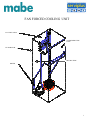
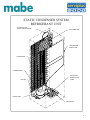
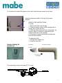
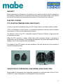
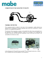
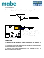
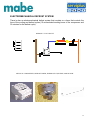
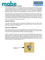
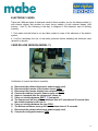
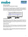
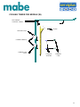
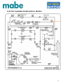
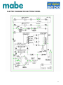
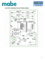
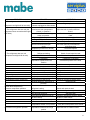
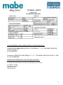
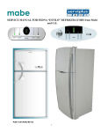
Service Manual
Moffat
ELECTRONIC POLAR WITH EXTERIOR DISPLAY
PUB # 06-MAN/RE-01
MTR12YATWW
December, 2006
1
CONTENTS
SECURITY
DISPLAY FEATURES
TEMPERATURE SELECTION
QUICK COOLING
VACATION
LOCK CONTROL
SPECIFICATION FOR FAN BLADE POSITION IN POLAR 12´ AND 14´
REFRIGERANT UNIT
FORCED AIR, AND NATURAL CONVECTION IN
CONDENSER UNIT
COMPRESSOR
FANS
ODOR FILTER
STARTING ELEMENTS (P.T.C)
DEFROST SYSTEM
DEFROST CIRCUIT
DEFROST SENSOR
DEFROST THERMOSTAT
FUSES
RESISTANCE
COOLING TOWER
STANDARD MODELS
TEMPERATURE CONTROLS
ELECTRONIC CONTROL CARD ( Z ), ( Y ), AND W
ELECTROMECHANICAL
TESTS
ELECTRIC DIAGRAMS
2
SECURITY
GENERAL INFORMATION
The new line of no frost refrigerators identified as MOFFAT 2001 in the capacities of 11, 13,
14, 16 cubic feet, are manufactured in the refrigerator plant of ”ASTRAL” located in the city of
Querétaro, Mexico.
The standard no frost refrigerators use electromechanical controls, the deluxe models use
electronic systems to control temperatures and defrost cycles, some models have the “QUICK
FREEZE” options (quick cooling) and a” VACATION” mode feature.
All models use 2 fan motors, one for the condenser and one for the evaporator
The new air tower for the internal air distribution has “TURBO PLUS COOLING SYSTEM”
that assures the appropriate temperatures for each refrigerated areas.
RESPONSIBILITY
The information provided in this technical manual are designed for qualified service
technicians who have knowledge in electricity, electronics and mechanics, it is intended to
guide the qualified personnel to carry out repairs in the refrigerators with automatic defrost,
any type of personal accident or to the property is the technician's responsibility so " MABE "
or " SERVIPLUS " can not accept responsibility for the use of this manual.
SECURITY
For your own security disconnect the power to the refrigerator before carrying out any repair,
if it is necessary to perform voltage measures, amperage, etc., reconnect the power only the
necessary time to carry out the test.
The complete assemblies of the electronic cards and the modules (elements) are very
sensitive to the electric discharges, special procedures are required for their handling as the
use of bracelets or antistatic gloves. DO NOT TOUCH NOR HANDLE THE CARD IF YOU
DON’T HAVE THE APPROPRIATE EQUIPMENT.
3
FEATURES
ALARM
It is activated or disabled by pressing the ALARM pad. You will then hear a tone and the
screen will display the letter “A” and the superior part of the button will be illuminated.
VACATION
To activate press the “VACATION” pad.
There are two ways to disabled the “VACATION” mode
1-By pressing the “VACATION” pad or 2- By opening the refrigerator door you will then hear a
tone and the superior part of the button will be illuminated, besides the led indicator you will
see that the digit in the display will advance slowly until disabling the function.
COOLING LEVEL
Press this pad to change the settings of the refrigerator, the setting can be increase from 1
through 9. 9 being the coldest.
TURBO
Besides the led indicator you will notice that with this feature the refrigerator will cool quicker.
The digit of the screen will advance quickly for one hour. At the end of this period it will return
to its normal operation.
LOCK CONTROL
This function is to prevent any involuntarily settings changes. To activate or disable, push and
hold simultaneously the ALARM and VACATION pads for 3 seconds; the letter L will be
displayed for a short period and then revert to the refrigerator settings.
4
1- FAN BLADE ADJUSTMENT ON MOTOR ASSEMBLY “POLAR”
A CILINDRICAL GAUGE IS NEEDED FOR THE POSITIONING OF FAN BLADE.
SEE SPECIFICATION BELOW:
For models the 11´,12,´13´y 14´ we have to use a depth of (11 mm.) marked CD.
For models the 15´,16´ 18´ we have to use a depth of ( 6 mm.) marked CA.
Figure 1.- Cilindrical Gauge
Figure 2.- Depth Fan Blade
5
EVAPORATOR
FAN MOTOR
CONDENSER FAN MOTOR ASSEMBLY
6
FAN FORCED COOLING UNIT
ACCUMULATOR
CONDENSER TUBE
LOOP
EVAPORATOR
RETURN TUBE
DRYER
7
STATIC CONDENSER SYSTEM
REFRIGERANT UNIT
SUCTION LINE
(HEAT EXCHANGER)
EVAPORATOR
CONDENSER
TUBE LOOP
CONDENSER
COMPRESSOR
DRYER
AUXILIARY
SERPENTINE
TUBE
CAPILLIARY
DRAIN PAN
8
If it is required to replace the display or the card, follow the steps shown in the figure.
Press the display and slide to the right as the arrow
indicates.
ODOR FILTER INSTRUCTIONS
To install
1.- Remove the filter from the bag
2.- Clean the plastic surface of the cartridge with a
dry rag, this to clean the dust.
3.- Place the filter at the top of the cooling tower, as
shown in figure A, this filter is attached by clips
located in the back of the cartridge.
It is important to make sure that the cartridge has
been correctly installed.
To replace the filter
1.- Pull the filter towards you.
2.- Install the new filter.
Interior display for
models (y)
FIGURE A
COOLING TOWER
FILTER
ASSEMBLY
This compressor uses a solid state (P.T.C.) relay.
9
SECURITY
Before connecting the refrigerator to the power source, make sure that all electric connections
are isolated, all harnesses are connected and are away from any sharp edges of the cabinet
and that all the internal and external electrical grounds of the product are connected.
ELECTRIC SYSTEM
PTC (POSITIVE TEMPERATURE COEFFICIENT)
Contrary to the electromechanical relay, the PTC doesn't have a coil neither mobile contacts.
A PTC is a thermistor, in other words, it is a resistance sensitive to the heat, which increases
its resistance in Ohms as the temperature increases.
The element of work of the PTC is basically a board of Titanium of Barium of high purity with
an aluminum covering.
When the PTC receives a voltage, initially high power circulates through it, elevating its
temperature and its resistance, by increasing the resistance the power that supplies the start
winding of the of the compressor falls considerably.
This capacity of the PTC makes it act as a substitute of the work carried out by the contacts of
the electromechanical relay.
PTC
BARIUM
TITANUM TABLET
CAPACITOR OF CONTINUOUS LOAD (WORK) (RUN CAPACITOR)
Some models of refrigerators have integrated a capacitor of continuous load or Work of 12mf.
A 200 A.C.V. that is connected in a circuit parallel to the connections
10
CONNECTION OF THE CAPACITOR TO THE PTC
PTC
L
CAPACITOR
THERMAL PROTECTOR
This component (which is placed in the body of the compressor), quickly detects any
abnormal rise of temperature or excess amperage draw caused by a mechanical or electric
problem or an inappropriate application.
This element of the compressor consists on a bimetallic disk, which, when overheated due to
the warming of the integrated resistance caused by an increase of the amperage the
bimetallic disk bend and disconnect the compressor, after the disk has cool down it will
reestablishes the electrical contact.
THERMAL PROTECTION
RESISTANCE
BIMETALLIC DISK
In this refrigerator the Thermal Protector and the PTC are contained inside a box, in which
the 2 component are connected together in the compressor.
11
DEFROST CIRCUIT
The defrost circuit components are: control card, defrost sensor, relay num. 2 on card, output
connector “con 4”, defrost thermostat, fuses and resistance (heater).
When the processor has accumulated a
Minimum of 8 running hours of the
compressor and the sensor registers a high
resistance above 8.5 k. the card sends
12 v.d.c. to the relay and energize
the heater to start the defrost cycle.
CONTROL BOARD
FAN MOTORS
The refrigerator has two fans motors, one in the freezer section and another for the
condenser and operate with 127 volts a. c.
The evaporator fan motor circulate the warm air through the evaporator and returns cold air to
the freezer and refrigerator fresh food section.
The condenser motor dissipate the heat generated by the condenser unit due to the
refrigerant circulating through the tubing.
12
ELECTROMECHANICAL DEFROST SYSTEM
There is also an electromechanical defrost system that consists on a timer that controls the
time of the cooling and defrost cycles (10 accumulated-working hours of the compressor and
35 minutes for the defrost cycle).
DEFROST CYCLE CIRCUIT
PHYSICAL COMPONENTS; DEFROST TIMER, THERMOSTAT (KLIXÓN) AND HEATER.
13
ELECTRONIC DEFROST SYSTEM
If the resistance (heater) is connected 20 minutes in the defrost cycle, the next defrost cycle
will be increase by 2 hours, if it is connected 30 minutes it will remain as it is, if heater stays
energize for 40 minutes it will decrease the next defrost cycle by 2 hours, this way it programs
the defrosting within ranges of 8 hours minimum to 12 hours maximum, increasing or
diminishing 2 hours, it never carries out the change from 8 to 12 hours or from 12 to 8 hours.
When the refrigerator is already working and it is disconnected for a short time or if there is an
interruption in the electric power supply, it loses the memory stored in the card, with respect
to the time that the heater remained connected in the last defrost cycle, when it reaches the
cut temperature indicated by the potentiometer and the sensor of the refrigerator, it turns off
the compressor and carries out a defrost to obtain the registration of the time that the heater
will be connected and to program the next defrost.
DEFROST SENSOR
The function of the defrost sensor is to disconnect the heater once frost has melted of the
evaporator. When the temperature reaches the specification range of the sensor, then the
circuit opens, and heater is de-energize.
DEFROST THERMOSTAT
The defrost thermostat consists of a single pole switch, a bimetallic disk and a pressure pin;
these elements are inside a metallic cylinder filled with epoxy paste. Two connection cables
come out from the cylinder which are soldered to the internal terminals.
If after a maximum of 40 minutes the defrost sensor didn’t disable the heater and the
thermostat shut off temperature is reached, the bimetallic disk (defrost thermostat) will then
disconnect the circuit to the heater. When the temperature of the evaporator lowers enough
(depending on the specifications of the thermostat), the bimetallic disk recovers its form and it
reconnects the terminals again, this way the bimetallic thermostat acts as a safety to avoid
that the temperature increases higher than 22 °C.
BIMETALLIC SECURITY
THERMOSTAT
14
ELECTRONIC CARDS
There are 2 different types of electronic cards for these models, one for the deluxe models (y)
with internal display and another for super luxury models (z) with external display (see
pictures 1 and 2), the following is the way to diagnose if the electronic card is working
correctly.
1. First make sure that there is not any false contact in none of the elements of the electric
system.
2. It will be necessary the use of anti-static protection before handling the electronic card
(bracelet or gloves).
CARD DELUXE VERSION (MODEL Y):
Verification of normal and defrost operation.
a)
b)
c)
d)
e)
f)
g)
Disconnect the cabinet (disconnect power supply cord).
Disconnect the harness of the freezer sensor CON1.
Disconnect the harness display from connector CON3.
Connect the cabinet (connect power supply cord).
Approx. 4 seconds later the compressor comes on.
Carry out a bridge between GND T_P (test point).
The compressor will turn off in a maximum time of 5 seconds and 5 seconds later
the defrost resistance will turn on.
h) Carry out a bridge between the pins CON1.
i) The defrost resistance must go off in a maximum time of 10 seconds.
j) Disconnect the cabinet (disconnect power supply cord).
k) Connect the refrigerator sensor CON1.
15
l) Connect the harness display to connector CON3.
m) Assemble the tower again.
n) Energize the cabinet (connect power supply cord).
CARD VERSION SUPERLUXURY (MODEL Z)
DELUXE MOFFAT CARD
CARD VERSION SUPERLUXURY (MODEL Z):
Verification of normal and defrost operation.
a)
b)
c)
d)
e)
f)
g)
h)
i)
j)
k)
l)
m)
n)
Disconnect the cabinet (disconnect power supply cord).
Disconnects the harness of the freezer sensor CON1.
Disconnect the harness display of the connector CON3. Option 2 leave connected.
Energize the cabinet (connect power supply cord).
Approx. 4 seconds later turn the compressor on.
Carry out a bridge between T_P and GND (be careful do not touch the marked pin as
v12 of the CON3. Use connector 1 pin type.
The compressor will go off at a maximum time of 5 seconds and 5 seconds later the
resistor of thaw will come on.
Carry out a bridge among the pins the CON1.
The resistance of thaw will be turned off at a maximum time of 10 seconds.
Disconnect the cabinet (disconnect power supply cord).
Connect the sensor of the freezer CON1.
Connect the harness display to the connector con3 and position external display in the
number that was originally (this is because when being connected again it will put
automatically in position 1).
Assemble the tower again.
Energize the cabinet (connect power supply cord).
16
TEMPERATURE CONTROL (ELECTROMECHANICAL)
This component controls the temperature of the refrigerator maintaining it within the preset
limits. The electromechanical control is able to control the temperature through a sensitive
hollow bulb (capillary) full with refrigerant, which contracts or expands according to the
temperature that is measuring.
Those temperatures at which the control starts or stops the compressor are called
respectively "cut temperature" and "start temperature" and they are the ones that should be
revised with a thermometer to see if the control is well calibrated or not.
COLD AIR
CAPILLARY
BELLOW
CONTACTS
AXLE CONNECTED TO THE KNOB
17
DIRECT TEST FOR THE ELECTRONIC CARD
TEST OF THE REGULATED VOLTAGE OF THE CARD
The tests that are indicated should be carried out through the sensor located in the fresh
foods compartment and the potentiometer (temperature control) integrated to the card,
whenever some of these components are damaged the complete assembly should be
changed, since each card is calibrated with these components.
ELECTRONIC CONTROL TABLET
When applying 127 A.C.V. in the white and black cables the card is energized, if the internal
operation is correct, it should measure 12 v.c.d. between the test points GND and V12.
OPERATION OF THE COMPRESSOR
ELECTRONIC CONTROL TABLET
18
DEFROST OPERATION
ELECTRONIC CONTROL TABLET
When voltage is applied between the white and black cables the card is energized, after 10
seconds it sends the signal to start the compressor, in that moment a bridge should be
connected between the test points GND y T_P, the compressor will then go off, three seconds
later it will send the signal to start the Defrost cycle, you should measure 127 V.A.C. between
the white and blue cables.
NOTE: If the freezer sensor is connected and does not register temperature, the signal to
initiate the defrost cycle will not be sent by the card.
19
THERMISTORS TEST
The thermistors varies their resistance according to the temperature that they detect, at
ambient temperature they have little resistance, when diminishing the temperature the value
of the resistance is increased, the approximate readings are shown according to a scale of
temperatures in the chart, in fact the important thing in the thermistors is that they should not
measure a resistance with infinite value (open) or zero resistance (closed), and when
warming or cooling down they should vary the value of the resistance.
The thermistors located in the freezer and the fresh food have the same characteristics and
the values are same, the difference is the connector type and the temperature to which they
send the signal to the card.
NOTE: the values between the readings are variable, since the thermometer measures the
temperature faster than the thermistor because it is encapsulated, if the thermistor maintains
to a constant temperature the value of the resistance will be higher, since it will stabilize the
temperature of the thermometer and the thermistor.
COMPRESSOR CYCLE
When the electronic card sends the signal to activate the compressor cycle, the potentiometer
and the temperature sensor start working to precisely regulate the compressor cycle and to
maintain the foods in the selected temperature.
The range of temperatures at which the compartment of fresh foods should be maintained is
indicated to the sensor by rotating the knob of the potentiometer, based on these ranges, it
sends a signal to the compressor to control the on and off cycles.
20
SPECIAL FEATURES
FEATURE SUPER COOLING (QUICK COOLING)
When selecting this option the LED2 will come on indicating that the signal is being sent to
the card, when the cut temperature indicated by the thermistor and the potentiometer is
reached, the card does not send the cut signal to the compressor, it continues working for one
more hour without stopping, the LED will go off when the compressor turns off; the time of
additional work and how it diminishes the temperature is reflected in the graph.
REGISTRATION OF TEMPERATURES IN THE EVAPORATOR
VACATION FEATURE
When selecting this function the “LED1” comes on indicating that the signal is being sent to
the card, the defrost cycle will activate according to the time stored in the memory, the
following defrost will be carried out at the 48 hours of accumulated time of work of the
compressor, the function fades when opening the refrigerator's fresh food door through the
photocell integrated in the card.
OPERATION TEST
Select the vacation feature, the “LED1” must come on, cover the orifice that is in the superior
front part of the air tower on the roof of the refrigerator to the right side of the screw that
fastens the air tower, wait for a moment and uncover the orifice, in that moment the “LED1”
must go off disabling the function.
When the refrigerator is energized, approximately 10 seconds after the electronic card sends
the signal to activate the compressor cycle, the potentiometer and the temperature sensor in
the refrigerator are now in operation.
21
COOLING TOWER FOR MODELS (W)
ELECTRONIC
CONTROL TABLET
SNAPS
NEW DIE CAST
CURRENT KNOTS
CURRENT DIE
CAST
CURRENT
SCREWS
CURRENT
CAPS
22
GENERAL CHARACTERISTICS
Error!
RESÍSTANCE READING IN COLD
RESÍSTANSE READING IN WARM
127 VOLTS A.C.V.
Refrigerant : R 134- A
Refrigerator Polar 12´: 120.5 grs. +/- 3.54 grs.
Refrigerator Polar 18´: 100.00 grs.+/- 3.54 grs.
23
ELECTRIC DIAGRAM FOR MECHANICAL MODELS
24
ELECTRIC DIAGRAM FOR ELECTRONIC MODEL
25
ELECTRIC DIAGRAM FOR ELECTRONIC MODEL
26
PROBLEM
1.- The refrigerator does not cool ( the
FAILURE
No power at outlet
compressor and light bulb do not work)
Harness unplugged or false contact.
2.- The refrigerator does not cool (the Potentiometer knob (temperature
compressor does not work and the light
Control ) to position 0.
bulb does).
Electronic card does not send signal
to the compressor.
Refrigerator in Defrost cycle.
PTC defective.
Thermal Protector open
Harness connection with open
circuit
Compressor (burned out or forced)
3.- The refrigerator does not cool
(compressor and light bulb do work)
4.- The refrigerator does not cool
enough ( the bulb illuminates an
the compressor works excessively).
5.- Refrigerator (freezes food
in fresh food compartment),
excessive compressor operation.
Refrigerant leaking
Refrigerant failure restriction
Compressor
Temperature control knob in low
Position
Electronic card does not send signal
for the Defrost (evaporator blocked
with ice)
Defrost heater with open circuit
(evaporator blocked with ice)
Defrost thermostat with open circuit
(evaporator blocked with ice)
Defrost sensor in short circuit.
Fan Motor defective ( burned out or
jammed).
Refrigerant Leaking
Magnetic seal does not seal.
Door does not close well.
Switch light bulb defective (bulb on
with door closed).
Temperature control knob in high
Position
Temperature Sensor out of position.
6.- Excessive refrigerator operation
Temperature Control Knob in high
position
CORRECTION
Check outlet
Plug or replace harness
Adjust the knob to position different
than 0.
Check the correct operation of the
Card.
Check cycle and wait until its finished
Replace PTC.
Replace thermal protector.
Check the continuity of the harness
and connections
Check and replace
Search for and repair the leak
Search and repair restriction
Change the compressor
Increase the position of the knob.
Check the correct operation of the
Card.
Change defrost heater and
melt ice
Change defrost thermostat and
melt ice.
Change or review the harness sensor.
Change the fan
Search and repair the leak
Repair or change the magnetic seal.
Adjust the door
Connect or change the switch or adjust
the door to make it work.
Adjust the knob to a lower number.
Verify the correct position of the sensor.
Adjust the knob to a lower number.
27
THE COMPRESOR USE IN SEDNA (ESTILO) REFRIGERATOR IS:
COMPRESSOR CBE121L2G DOE/FIDE FOR SEDNA 17´ Y 19´ THE SAME FORM FOR
POLAR 16¨AND 18´
IS 3.8 AMPERES.
Compressor CBZN100L2 PARA SEDNA 13´ Y 15´ THE SAME FORM FOR POLAR 12´ AND
14´ IS 3.8 AMPERES.
OPERATING PRESSURES: LOW SIDE AND HIGH SIDE :
De acuerdo al plano estos son los valores para el SEDNA
According to the Label these are the values for sedna (Estilo) is the following.
(Low Side) 0 , 97 Mpa
(High Side) 2, 31 MPa
High Side 335 PSI
Low side 140 PSI
28