1
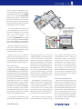
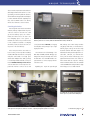
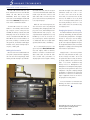
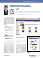
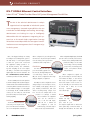
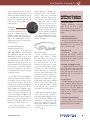
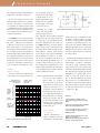
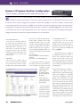
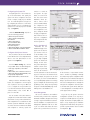
Issue 15.1
Spring 2004
A Next-Generation ”System Switcher”
for Single Projector Applications
The Extron System 5 IP
FEATURE ARTICLE
1 A Next-Generation
System Switcher
for Single Projector
Applications
The System 5 IP
COLUMNS
4 Unique Techniques
Kennesaw State University
7
8
W
ith A/V increasing its prominence in the corporate and
education markets, demand for feature-rich components is
growing as fast as we can make the technology available. Typically,
Extron Hotline
presenters are not intrigued by all the bells and whistles in A/V prod-
Online Applications Section
Provides a New Design and
Educational Resource
ucts unless they’re user-friendly. For a presenter, combining all of the
Featured Product
After all, the presenter has more pressing issues to address than figuring
IPL T SFI244 Ethernet
Control Interface
elements into one, easy-to-use system is a step in the right direction.
out how to run complex A/V equipment.
10 Technically Speaking
The Mysterious Loudness Control
14 The IP Link
It's All About the Network
18 Tech Corner
System 5 IP System
Switcher Configuration
ALSO IN THIS ISSUE
16 New Products
13 New News
20 Tweeker Use
This dilemma makes the Extron System 5 IP
system switcher a sensible and timely choice
for any single projector application. An upgrade to the popular System 5cr Plus system
switcher, the System 5 IP has many enhancements that make it an all-in-one, economical
solution for single projector A/V installations
in classrooms, boardrooms, and conference
rooms. This five input integrated A/V switcher
is loaded with feature and performance, making it perfect for applications that require
a flexible, full-featured product that installs
quickly and is very easy to operate.
New Features
In response to customer feedback, we’ve
incorporated significant enhancements into
the System 5 IP. Along with additional configurable inputs and relays, the System 5 IP
also features increased bandwidth, a more
powerful built-in audio amplifier, front panel
backlit input buttons, and compatibility with
a wider selection of projectors and our
own extensive line of control options and
IR Control Modules (IRCMs). To top it off,
continued on page 2
SYSTEM 5 IP
The System 5 IP: A Next-Generation System Switcher
Control
Control
Control
Control
Video/RGB
(cont.)
Video/RGB
SYSTEM 5 IP
Audio
INPUT 5
PC VIDEO
IR
AUDIO
CONFIG
Extron
System 5 IP
PROJECTOR
VOLUME
DVD & VCR CONTROL
PROJECTOR
ON
PROJECTOR
OFF
LIGHTS
ON
LIGHTS
OFF
PC
INPUT
3
INPUT
4
INPUT
5
FUNCTION
BUTTON
DVD
Tx
VCR
TITLE
MENU
ENTER
TV/VCR
TUNER
PROJECTOR
DISPLAY
POWER
IR
CONFIG
DISPLAY
MUTE
ROOM
RELAY
1
ROOM
RELAY
2
ROOM
RELAY
3
SYSTEM 5 IP
VOLUME
INPUT SELECTION
INPUT 5
CLIP
PC 1
DESKTOP
1
2
VCR
DVD
LAPTOP
MENU
NEXT
SIGNAL
3
4
PC VIDEO
NORMAL
5/ PC
AUDIO
Network
PREV/REW PLAY NEXT/FWD PAUSE
Video
ADJUST
RGB
INPUT
1
INPUT
2
STOP
SCP 150 AAP
Extron
System 5 IP
Control
VCR
Extron
SCP 150
with IRCM DV+
Video
DVD
Control
Laptop
Video/
RGB
RGB
RGB
Document
Camera
tors and displays. These drivers enable the
System 5 IP to control common projector
functions such as power and input selection.
Users can create their own drivers or go to
the Extron Web site (www.extron.com) to
download drivers pre-configured for the latest
and most popular projectors. This alone makes
the System 5 IP an instant hit with schools and
businesses where display devices are frequently replaced. In addition, the switcher features a
custom configuration mode to allow for userdefined RS-232 or IR commands.
Video
DVD/VCR
Combination
Audio
Control
PC
Laptop
Help Desk
Two or more rooms with the System 5 IP can be monitored over a network via IP Link technology.
the System 5 IP is equipped with IP Link™,
an IP integration technology developed by
Extron to meet the needs of professional A/V
environments.
Configurable Inputs
The System 5 IP includes two configurable
inputs for composite video, S-video, and
RGBHV. Two additional inputs are configurable for composite video or S-video on BNC
and 4-pin mini DIN connectors. In addition,
the System 5 IP has a front panel input for
RGBHV on a 15-pin HD connector. This makes
it convenient to directly plug into a laptop or
document camera without accessing the back
of the switcher.
display screens via one relay, the user has the
flexibility to control each room device separately and at any time via the six relays.
The flexibility of multiple room control relays in a classroom or boardroom makes it
possible for the presenter to stay focused on
the presentation, without fretting about how
to control the display screen or lighting.
Universal Projector Control
More Relays
For more than 10 years, universal projector
control has become synonymous with Extron
system switchers. The System 5 IP continues
this tradition by providing universal projector
control via a dedicated, bi-directional RS-232
projector control port, as well as IR learning
capabilities. Both features allow the switcher
to operate with RS-232 and IR controllable
displays. The switcher can learn IR signals
from the remote control included with the
display. From there, the switcher communicates between the display or projector and
sources such as VCRs and DVD players. The
System 5 IP is equipped with four IR/serial
control ports, which are not only useful to
control external sources, but a second projector or display as well.
The System 5 IP increases room control capability with six configurable internal relays.
Now, instead of having to simultaneously
control room lighting, window coverings, and
Engineers at Extron create and administer
a large selection of commonly used projector
control drivers for a wide variety of projec-
With its configurable inputs, the System 5 IP
enables users to mix and match a variety of video and computer sources in small classrooms
or boardrooms. Regardless of the application,
the System 5 IP offers the flexibility to switch
between high resolution RGBHV/computer
signals and standard definition (composite
video, S-video) signals without sacrificing the
integrity and flow of the presentation.
2
ExtroNews 15.1
The System 5 IP also offers many audio feature
enhancements. It includes two line level outputs
(one fixed and one variable) for use with external
recording or signal processing equipment. Also,
the fixed outputs of the System 5 IP enable integrators to install a system that is compliant with
ADA requirements, which specifies effective
communication in presentation environments
for people with hearing loss. The System 5 IP
can be connected to an assistive listening device to meet these requirements. The switcher’s
variable audio outputs are adjusted by the front
panel volume control or via remote control.
Another improvement is the System 5 IP’s
internal, 40-watt (2 x 20 watts rms)
audio amplifier, which can drive 4 or 8 ohm
speakers. The unit can be set for stereo or dual
mono mode, in which it sums the left and right
input signals together and drives the same
mono signal to both the left and right outputs.
Control Options
There are a number of control options available on the System 5 IP that help simplify the
Extron SCP 150 AAP shown with Extron
IRCM-DV+ IR Control Module
Spring 2004
switcher’s overall functionality. Users can operate the System 5 IP by selecting the switcher’s
front panel backlit buttons, the optional IR 402
remote control, or optional SCP 150 Series
hardwired control pads. For installations that
only rely on the switcher’s remote control capabilities, the System 5 IP is offered without front
panel controls, but still provides the front panel
15-pin HD input connector for RGBHV.
The optional IR 402 remote and SCP 150
control pad duplicate the System 5 IP’s front
panel functions and enable users to remotely
control the switching, projection, and
room functions. In addition to the
SCP 150, the SCP 150 AAP includes openings
for up to four single space Architectural Adapter
Plates (AAPs) including IR Control Modules
(IRCMs), for VCRs, DVD players, and tape decks.
����������������
Both the SCP 150 and SCP 150 AAP (shown
at left) can be mounted in a wall, podium, or
table, and are available in gray, black, or white
to blend in with the environment.
Whichever way you choose to operate the
System 5 IP, these options make it easy to customize an A/V system and address the needs
of just about any small-scale application where
simplicity is integral to optimum integration.
IP Link™ Technology
The System 5 IP includes an entirely new feature added to many of Extron’s flagship products:
IP Link. Utilizing Ethernet connectivity and an integrated Web server, the IP Link feature allows
the System 5 IP to remotely monitor and manage
most projector and A/V system functions from
any computer with a standard Web browser.
IP Link enables the System 5 IP to proactively
manage and troubleshoot a system over highspeed local area networks (LANs), wide area networks (WANs), or the Internet. The included Web
server can be customized for common functions
such as I/O switching, system control, security,
online diagnostics, and proactive monitoring
through user-friendly graphical interfaces.
In one example, the IP Link feature of the
System 5 IP gives the administrator of an educa-
www.extron.com
�����������������������������
���������������������
������������������������
�������������������������
���������������������
�������������������
���������
tional facility the ability to access, monitor, and
troubleshoot any device connected to any Sytem
5 IP from a single location. The Extron IP Link
Global Viewer is a key asset management tool
that allows the administrator to identify which
A/V products are connected to the System 5 IP.
Once the products are identified and configured,
the administrator can view the entire A/V system on the network via any Web browser such
as Microsoft® Internet Explorer or Netscape®
Navigator. From there, the administrator is able
to oversee all the connected products from the
convenience of a single workstation.
alerts, schedule routine equipment activity,
or run maintenance checks on lamp hours,
environmental conditions, connectivity, and
other issues vital to operations. For instance,
the administrator can configure the projectors to power on or off at pre-selected times,
while each device is automatically monitored
via its connection to the LAN. As a result,
downtime is minimized because equipment is
proactively serviced, the administrator knows
the status of all devices at any time, and utility expenses are reduced.
A Great Switcher Made Better
The administrator can track the projector
lamp hours in each classroom and generate an
e-mail alert well before its maximum lifespan
to avoid unexpected lamp failure. The alert
sent by the System 5 IP is received by e-mail
via a computer, cell phone, PDA, or pager. The
administrator can then order and replace the
new lamp before the existing one burns out.
IP Link includes a real-time clock that allows the administrator to program operating
When it was introduced, the System 5cr Plus
was promoted as an all-inclusive solution for
small-scale applications. With enhanced control
features including IP Link monitoring, stronger
audio amplifier, backlit input buttons, an intuitive LCD interface, and an inactivity timer, the
System 5 IP has harnessed the power of the
System 5cr Plus and expanded on its capabilities to create an easy-to-use, next-generation
system switcher for today’s sophisticated classrooms and boardrooms.
3
F ENAI T
U
Q UU RE E TD E P
CR
HO
ND
I QU UC ET SS
Kennesaw State University: Putting the Cart Before the Course
F
rom its humble beginnings as
a small railroad town and ma-
jor battleground of the Civil War
to the northwest Atlanta suburb
of today, the city of Kennesaw
thrives on tradition, community,
prosperity, and education. Driving
this last point home is Kennesaw
State University (KSU), one of the
fastest growing learning institutions in the United States. Opening
in 1963 as a junior college, KSU is
now Georgia’s fourth largest state
university, with almost 18,000 students and 55 undergraduate and
graduate degree programs.
Nine Electronic Classrooms
In its Guide to America’s Best Colleges and
Universities, US News & World Report called
KSU one of the “rising stars of education.” To
maintain its distinction as an “up and comer,”
the school’s administrators realized they had
to harness technological advancements that
many learning institutions are embracing. Dr.
Randy C. Hinds, Chief Information Officer and
Professor of Information Systems, and Karl C.
Aldag, Director of Presentation Technology,
explored new concepts regarding high tech
tools and the school’s classrooms. Aldag
noted that KSU had outgrown the basic multimedia pushcart and simply didn’t have the
staff or resources to maintain and/or check
equipment in and out. This led to the idea of
an integrated multimedia system.
In the summer of 2003, Hinds, Aldag, and
KSU’s technology advisory committee decided
to move forward with their plan for a functional electronic classroom. They envisioned a
room with a desktop computer, and a way to
4
ExtroNews 15.1
Kennesaw State University serves a diverse student body in Atlanta, GA. US News & World Report called the
school one of the “rising stars of education.”
plug in a laptop computer. They also wanted
to tie in an A/V system that could be intuitively controlled without a separate remote.
“We needed an integrated system that was
easy to use and control,” Aldag said.
The green light was given to KSU’s inhouse Presentation Technology Department
(PTD) to turn the initiative into reality. Led by
Charles Huberty, System Support Specialist II,
the team spent two and a half weeks assembling nine multimedia carts for nine separate
classrooms. The lower section of each cart
includes two racks filled with several A/V
components: a VCR, a DVD player, a CPU,
an audio mixer, an auxiliary XLR microphone
jack, and an Extron System 7SC, a seven input, dual output, multi-format switcher with
a built-in video scaler.
The System 7SC Runs the Show
“The System 7SC was chosen for its scaling, switching, and projector control ability,”
Huberty said. The System 7SC has rightfully
earned the distinction of being an all-purpose,
single-projector hub that provides switching,
scaling, and projector and room control. Its
capacity to integrate these functions along
with RGB and video capabilities makes the
switcher that much easier to operate for the
KSU faculty. The instructors can control many
of the features of the System 7SC by simply
pushing a button on the installed Extron
MLC 206 AAP MediaLink Controller.
The dual outputs of the System 7SC is another unique feature that Kennesaw used to
their advantage. An LCD computer monitor
mounted on the cart is often used as a local
monitor during a presentation. Aside from routine switching, the System 7SC’s scaling feature
is a big plus for the Kennesaw faculty, who tap
into a variety of different signal types.
To scale any video input, the System 7SC
incorporates several of Extron’s proprietary
technologies. This includes Dynamic Motion
Interpolation (DMI™), an advanced motion
Spring 2004
UNIQUE TECHNIQUES
detection and compensation method that enables image enhancement with no loss of image fidelity; 3:2 and 2:2 pulldown detection,
which maximizes image detail and sharpness
for NTSC and PAL materials originating from
film; and Accu-RATE Frame Lock (AFL™),
which solves frame rate conversion issues.
Scratching the Surface
Even though the carts have been rendered
immobile, Huberty explained that they were
“the best solution at the time. We could
get the most tabletop space out of them.”
Indeed, the surface area of the carts is the
most intriguing aspect of the systems. To
maximize the surface area, an LCD monitor
for the computer is attached to a swinging
arm which, in turn, is bolted to the front center portion of the cart’s tabletop.
Holes were precut in the cart’s surface to
house a variety of Extron products including:
the MLC 206 AAP, which fits into a five-gang
wall plate and includes four single space
Architectural Adapter Plate (AAP) openings
for controlling all audio and video sources; an
Extron HSA 400 Hideaway Surface Access
enclosure that allows for inconspicuous computer-video interface connector access and
A close-up of the multimedia cart’s surface shows control panel and connection options: an Extron HSA 400
Hideaway Surface Access enclosure, MLC 206 AAP MediaLink Controller, and AAP 104.
control; and an Extron AAP 104, a four-gang
size wall plate with openings for up to eight
single space AAPs.
The PTD team took full advantage of the
MLC 206, HSA 400, and AAP 104 by populating them with pass-through and control
module AAPs. The HSA 400 includes two
optional AAPs: to connect a laptop with another A/V source.
Regarding the 15-pin HD pass-through
AAP, Huberty said: “Our faculty members
carry laptops with them, so we want them to
walk in, plug in, and go. We are also using
document cameras with VGA outputs.” He
added that the RCA pass-through AAP is “for
camcorders, a DV-cam, or a mini DV deck.
If they come in with an old beta tape, we’re
prepared. And we also have some older document cameras that use composite.” Huberty
mentioned that the RJ-45s that come standard
on the HSA 400 allow faculty members to plug
in their laptops to access KSU’s network.
The multimedia cart’s equipment rack includes an
Extron System 7SC, with a VCR and DVD player.
The multimedia carts enable instructors to switch and execute a wide variety of computer-video, video, and
audio signals. One KSU professor claims the carts have “completely changed the dynamics of teaching.”
www.extron.com
continued on page 6
5
UNIQUE TECHNIQUES
Kennesaw State University
(cont.)
The MLC 206 and AAP 104 have each
been outfitted with one IR Control Module
(IRCM). The MLC 206 has an Extron
IRCM-DVD+, which offers transport and
menu controls for a DVD player. The AAP 104
has an Extron IRCM-VCR, which provides remote control of a VCR’s basic features.
The MLC 206 controls five sources. In
addition to the auxiliary VGA and auxiliary composite sources coming from the
HSA 400, the desktop computer, VCR, and
DVD player that are all mounted on the
cart are controlled with the MLC 206. “The
MLC 206 was chosen for the number of inputs it has, its ability to communicate with
the System 7SC, the modules for DVD player
and VCR control, and its relatively inexpensive price,” Huberty said.
Making the Connection
Once the carts were assembled and loaded up with computer and A/V equipment,
the PTD staff wired everything by hand.
Huberty said that virtually no pre-manufac-
tured cable was used, with the exception
of two Extron VGA with Audio Cables that
include 15-pin HD male connectors and
audio cables with a 3.5 mm stereo mini
jack on each end. These are primarily used
to hook up the laptops.
While the carts were being wired, another crew was in each room pulling and
terminating cables, hanging speakers and
projection screens, and installing the multimedia XGA LCD video projector. “The
only infrastructure requirements not solely
handled by us were the electrical outlets, network jacks, and the replacement
of chalkboards with LCS (Liquid Chalk
System®) marker boards,” said Huberty.
As for connecting the projector to the
System 7SC, Extron BNC-5 Mini HR Cable
was used. Lighter, smaller in diameter,
and more convenient to install than standard coaxial cable, the Mini HR cable
offers excellent video performance for
carrying high resolution signals. Huberty
stated that the length of the cable runs and
termination varied from room to room.
“In some of the rooms we ran the cable
in the walls,” he said. “But if the cart was
moved to the middle of the room, which
some of our faculty members asked for, we
ran raceway molding on the floor so the
cable could be fed to the cart without anyone tripping over it.”
Changing the Dynamics of Teaching
Even with a limited time allotted to get the
systems up and running, the PTD technicians
encountered very few problems. “The biggest
obstacle for this project was retrofitting,”
Huberty remarked. “Our job was to try and
get all of the requested equipment in a space
the faculty wanted and not have a noticeable
degradation of quality, both in the image and
in the instructor’s presentations.”
Largely because of the Extron products
that were used, Kennesaw was able to get
the most “bang for the buck.” As for how
the systems have been received, the university’s faculty couldn’t be more positive in their
praise. “I love them!” exclaimed Dr. Gary
Roberts, Professor of Management in the
Management and Entrepreneurship department, who uses the system in his classroom on
a daily basis. “They have completely changed
the dynamics of teaching. In fact, I find it very
difficult now to teach in a room without the
range of equipment offered on our carts. It’s
like going back a century in time.”
For more information on Kennesaw State
University, visit them on the Web at http://
www.kennesaw.edu/.
Each multimedia cart houses all of the classroom’s
A/V and IT equipment, including the Extron
System 7SC system switcher.
6
ExtroNews 15.1
Spring 2004
TFHE EA TE UX RT ER D
O NP RHOODTUL CI N
TE
S
by Jeff Gibson, Vice President of Sales
Online Applications Section Provides
a New Design and Educational Resource
W
e’re pleased to announce a new resource on the Extron Web site
(www.extron.com) to assist you in your system integration design.
The new Applications section is a compendium of real-world case studies,
application diagrams, and selected products that demonstrate how Extron
devices are used effectively in a variety of settings.
Many of these applications were
created by our integrators, installers, and
consultants from unique requirements.
Education is one of our top priorities
at Extron, and we want to share these
success stories with you in the hope of
guiding those who encounter comparable
challenges.
The Applications section focuses on
six environments:
• Instructional Technology—
Classrooms, lecture halls, and auditoriums from K-12 through university levels
• Corporate — Boardrooms, conference rooms, and more
• Residential & Home Theater —
Automation, security, and home theater
• Courtroom — Law schools and
courtrooms
• Broadcast — Production studios,
non-linear editing suites, and video
server environments
• Rental & Staging — Concerts,
tradeshows, and other live events
Within each application area, you’ll
find application profiles, diagrams, and
products. Application profiles are indepth, analytical case studies that spotlight dealers and/or consultants using
Extron products. Application diagrams
go one step further and explore system
design options with several different
clearly, easy-to-visualize illustrations.
The Products section highlights Extron’s
products, based on their functionality
and relevancy to a given environment.
Altogether, these three links emphasize
www.extron.com
The new Applications section of the Extron
Web site features case studies, diagrams,
and products for several environments.
the importance of looking at system
integration from every angle to ensure
the best solution.
The Instructional Technology and
Corporate sections are the first sections
completed. In the months ahead, you’ll
see other helpful information added
to the section. To find the Applications
section, go to www.extron.com and
look for the tabs underneath the
Extron logo. Click on the Applications
tab, and you’re there.
Detailed diagrams provide potential solutions for a variety
of applications.
7
FEATURED PRODUCT
IPL T SFI244 Ethernet Control Interface
Latest IP Link™ Model Provides More A/V System Management Possibilities
T
he role of the technical administrator in todayís
organizations has expanded to include A/V system
asset management; increased responsibilities that can
overwhelm available budgets and staffing. Increasingly,
administrators are looking for ways to intelligently
Web-enable their A/V equipment. Integrating A/V systems into an IP network helps organizations leverage
limited resources and provides the same type of centralized remote asset management that IT managers enjoy
IPL T SFI244
for their systems.
One of the biggest challenges in creating
an intelligent asset management system is
the wide variety of control signals required
to make the system work. Professional
A/V equipment routinely provides a serial (RS-232) interface, but communicating with everything in the room requires
the ability to send and receive analog and
digital signals and send IR commands. The
IPL T SFI244 Ethernet Control Interface
from Extron provides all of that, and more.
The IPL T SFI244 packs the same punch as
its IP Link™ siblings with a built-in high performance Web server and full-blown Ethernet
connectivity. Where it stands out from the rest
is in the number and types of control signals
it can manage. The IPL T SFI244 includes 10
control ports: two serial ports, four Flex I/O
ports and four IR ports. It also boasts IR
learning capability.
Serial Ports
The IPL T SFI 244 offers RS-232
connectivity on two captive screw
ports for bi-directional communication of two independent serial devices.
8
ExtroNews 15.1
When configured for pass-through mode,
the interfaces can pass through commands
from an existing control system and
communicate with a single device.
Flex I/O Ports
Four Flex I/O ports can support TTL and analog signals from
0 to 24 volts, allowing management
of a wide variety of devices. The Flex
I/O ports can be configured in three ways:
analog in, digital in, or digital out.
Flex I/O ports can be configured to receive
analog voltages for use with photo sensors,
level feedback, strain gauges, thermocouples, variable potentiometers, and other
devices. Incoming analog voltages from
0 to 24 volts are sampled with 12 bit
precision. For example, a thermal
sensor installed in an equipment
rack can be connected to
one of the Flex I/O inputs,
and the IPL T SFI244 can
be configured to send an
e-mail message, if the rack temperature exceeds a specified threshold.
When configured as digital inputs, the Flex I/O
ports can connect to switches, motion sensors,
moisture sensors, and tally feedback. This
provides the ability to receive status
from a variety of devices, including
projector lifts, motorized projection
screens, room partition switches,
and push buttons.
When configured as digital outputs, the Flex I/O ports can drive LEDs, 24
volt incandescent lamps, or other devices
that accept a TTL input signal. For applications that require contact closure control, the Flex I/O ports can interface with
an Extron IPA T RLY4, an IP Link
Accessory
featuring
four isolated relays.
IR Ports
The IPL T SFI244
includes four fully
programmable
IR
ports. Each IR port
can output IR signals with or without the
carrier signal using a wired IR emitter or
through an IR broadcaster. IR control data
Spring 2004
FEATURED PRODUCT
can be collected and stored in two ways: IR
data file download and IR learning. Extron
maintains a vast library of IR data files that can
be downloaded from our Web site for storage in the IPL T SFI244. Each unit will power
four IR emitters, each up to 400 feet
(120 m) in length.
IR Learning
In addition, the IPL T SFI244
can learn IR commands for virtually any IR controllable device. IR
learning is a simple and easy process
using the IR remote that is provided with the
device to be controlled. Specific serial command strings can also be associated with specific IR commands.
gram operating alerts, schedule routine
equipment activity, or run maintenance
checks on lamp hours, environmental
conditions, connectivity, and other issues
vital to operations. For instance, the administrator may want to configure
the projectors to power on or off
at pre-selected times, while each
device is automatically monitored
via its connection to the LAN. As
a result, downtime is minimized
because equipment is proactively
serviced, the administrator knows the
status of all devices at any time, and utility
expenses are reduced.
Centralized Management
and Remote Monitoring
The IPL T SFI244 works with the
Extron Global Viewer™, a free Web based
asset management application that gives
administrators the ability to access, monitor, and troubleshoot all of an organization’s
A/V equipment from a single location. The
administrator can view the entire A/V system via any Web browser such as Microsoft®
Internet Explorer or Netscape® Navigator.
From there, the administrator can oversee all
rooms simultaneously from the convenience
of a single workstation.
In one example, a school’s IT administrator
can track the activity and status of the projectors installed in the school’s classrooms. Each
projector’s power, connections, lamp life, and
temperature, can be viewed. The administrator can even turn off all the projectors at once.
The IPL T SFI244 can be configured to generate an e-mail alert to the maintenance department at, for example, 1,350 lamp hours, well
before the life maximum of 1,500 hours. The
e-mail alert can be received by a computer, cell
phone, PDA, or pager. The maintenance department can then order and replace the new
lamp before the existing one burns out.
IP Link technology includes a real-time
clock that allows the administrator to pro-
www.extron.com
Additional Features
of the IPL T SFI244:
• Multi-user support
Multiple simultaneous connections
enable each IP Link device to support
many concurrent users and improve system throughput by sending information in
parallel.
• Two levels of security
with password protection
User access level authorizes limited entry to only pre-designated functions, while
administrator access level permits full
access to advanced settings.
• Real-time clock
IP Link Technology
The IPL T SFI244, like each IP Link
Ethernet control interface, is a small,
high performance, auto-sensing, auto-networking Web server with robust computing power. The IP Link
internal processor has a latency, or delay,
from the time it receives data to the time
it responds, of less than one millisecond,
meaning Web pages are served many
times faster than similar products. Each
IP Link interface features 1.25 MB of onboard flash memory for Global Viewer
Web pages and device drivers. The IP
Link operating system supports standard
Internet protocols such as DHCP for dynamic IP addressing, SMTP for sending
e-mail, and many others, ensuring full
functionality on existing IP networks.
With IP Link technology and the Global
Viewer software, the IPL T SFI244 goes
beyond the traditional approach to A/V
system management, enabling system
administrators to centrally monitor multiple rooms simultaneously, proactively
manage large quantities of equipment,
and intuitively automate routine tasks
and events.
Programmable
operating
alerts,
sequencing, and automatic monitoring
with the internal real-time clock and calendar allow the IPL T SFI244 to routinely
check the status of a device.
• Intuitive configuration utility
A supplied Windows® based configuration utility makes product setup simple
and easy. Drivers for a wide variety of projectors and Extron A/V products can be
downloaded from the Extron Web site
(www.extron.com).
• Power options
For added reliability, users can power up
the IPL T SFI244 two different ways. With
power over LAN (IEEE 802.3af), there is
no need for a local power supply. The
included external, international power
supply can also be used for worldwide
power compatibility.
• Versatile mounting options
The IPL T SFI244 comes in a 1U, quarter rack width metal enclosure and is rack,
under-desk, and projector-mountable.
9
FEA
T
CT
HU
N RI CE A
D L PL Y
R OSDP UE C
A TK SI N G . . .
by Steve Somers, Vice President of Engineering
The Mysterious Loudness Control
What Does It Do?
T
he first really decent stereo audio system I owned had a pushbutton on the front panel
called “loudness.” I pushed it. I decided the audio sounded better so I left it pushed in;
never changed it. OK, occasionally I would push it to the off position; nope, sounded better
on. Thinking back, I really didn’t care what it was for. I left it pushed ON because it made
the system sound better, so I continued to concentrate on my video career. All the while, my
stereo system “sounded good.”
Fast-forward 30 years. Here I am writing
about that pushbutton. That pushbutton
recently created considerable flurry here at
Extron. Since the inclusion of much more audio support in our products, that loudness
pushbutton finally crept into a prototype
product. Someone in Product Management
pushed it, but it didn’t do what it was supposed to do: make the system “sound
good.” That launched an investigation into
the real intent of the loudness control function and a bit of re-evaluation by those individuals designing audio products.
trol and why it should make an audio system
“sound good.”
Equal Loudness for All
Research characterizing the human hearing range generated an areal map of auditory
response as shown in Figure 1. The shape of
the minimum audibility curve tells us something about the frequency response of the ear
at low sound pressure levels. At the boundary of minimum audibility, perception of low
frequencies and high frequencies requires a
significant level boost as compared to the midrange frequencies. Conversely, at the upper
boundary the threshold of feeling represents a
much flatter response. The incomplete outline
of the graph indicates regions of extreme variability where performance data collected on
human subjects is not altogether consistent.
We learned something. Different people
and different companies have different design philosophies toward functionality of
the loudness control. So, when you push it,
what should the loudness control do? Let’s
begin answering that question with a look
at the historical basis for the loudness con-
140
Threshold of Feeling
Sound Level (dB)
120
100
80
Auditory Response Area
60
40
20
Minimum
Audibility Curve
0
20
50
100
200
500
1K
Frequency (Hz)
Figure 1: Realm of human auditory response
10
ExtroNews 15.1
2K
3K
10K
In the 1930s, two Bell Labs researchers,
Harvey Fletcher and Wilden
Munson, organized a research project in which they
asked that each participant
match the perceived level of
two pure tones by adjusting
the level of one tone source
against a 1000 Hz tone at
a pre-determined reference
level, until the two tones
were perceived as equal in
loudness. Their test results
20K
embodied data at many frequencies at various sound
pressure levels across the
human hearing range. Since this is a highly
subjective way to conduct research, many
subjects performed the experiment. Results
were averaged to obtain loudness contours
intended to represent a “normal” response.
Their results, called the Fletcher-Munson equal
loudness contours, provide significant insight
toward our understanding of how humans
perceive relative sound levels. In 1956, D.W.
Robinson and R.S. Dadson refined this work
in a similar study described as having more
reliable measurement results. The Robinson
and Dadson equal loudness contours shown
in Figure 2 are most widely used today, but
are often referred to as the Fletcher-Munson
curves. Eventually, the International Standards
Organization adopted the Robinson-Dadson
curves as a basis for “Normal Equal-Loudness
Level Contours,” ISO 226:1987, which is
now the current standard. Since these curves
describe the perception of only pure tones
in a free field, they do not necessarily apply
to noise band analysis or diffused random
noise.1 Additional research continues in an
attempt to further characterize our hearing
perceptions in real audio applications.
If we invert any of these contour curves
at a particular intensity level, we now have
the relative frequency response plot of the
human ear for all tones across the frequency
range on that particular contour. Inversion of
the lower curves illustrates human ear frequency response deficiencies at low sound
intensities. Conversely, invert any of the upper, higher intensity curves to realize a more
Spring 2004
T E C H N I C A L LY S P E A K I N G . . .
+15
power, but only a perceptible
increase in volume to the ear.
The red dashed line at the bottom of Figure 2 describes the
minimum audible level for hearing sensitivity in a free field.
+10
+5
D
0
-5
Relative
Response, dB
flattened frequency response. Fletcher and
Munson found human hearing response consistently deficient at low sound intensities, for
both low frequencies and higher frequencies
compared to the 1000 Hz reference point
used to establish these curves. But, the ear is
particularly sensitive in the range of about 300
to 6000 Hz. This happens to be the frequency
range that includes the sound of most human
speech patterns and, curiously, the pitch of a
crying baby. For average background sound
pressure levels, the rolled-off response at lower sound pressures allows us to more easily
listen and understand human speech in the
presence of low or high frequency noise.
-10
B&C
C
-15
-20
-25
A
D
B
-30
The effect of applying these
-35
curves suggests that some form
-40
A
-45
of filtering is required within
-50
measurement equipment if we
20
50
100
200
500
1000 2000
5000 10,000 20,000
wish to synthesize the normal
Frequency,
Hz in sound level meters
Figure 3: Weighting filter response
curves used
hearing performance of the
ear when calibrating systems
imating the 70 phon curve. Notice how the
or making value judgments as to sound qualear’s response begins to flatten. C-weighting
ity. Most often, the sound pressure level (SPL)
utilizes the 100 phon curve, which describes
Meet the Phons
meter is used to setup listening levels for an
the nearly flat response of the ear for high
Each contour is identified as a level in
audio system. The SPL meter includes selectlevels. The C-weighting response is most use“phons.” A phon is a subjective unit for loudable filters that modify its calibration so it
ful for typical home theater listening levels
ness equal to the sound pressure level in
approximates the ear’s response at a given
and for evaluating system performance for
decibels when compared to an equally loud
range of sound pressure levels. The most offlat response characteristics. The D-weighting
standard note. The standard note is a 1000
ten-used filter settings are the A-weighted
Curve is a special case developed for aircraft
Hz pure tone or narrowband noise centered
and C-weighted. What are these and how do
fly-over noise testing, which penalizes high
at 1000 Hz.2 Note that the level in phons
they relate to our hearing response?
frequencies.3 Likewise, sound level measurematches the sound pressure level in decibels
ments in decibels relative to these weighting
only at the 1000 Hz standard reference point
The concept of weighting refers to the relcurves are recorded as dB(B), dB(C), and
on the graph. Therefore, the 40 phon conative shaping of the filter’s response so as to
dB(D), respectively. The A and C weightings
tour represents a 40dB SPL at 1000 Hz, but
mimic the ear at a given loudness level. Four
are most often used since the former relates
a different SPL at most other frequencies.
weighted filter functions, A, B, C, and D, are
to normal everyday sound pressure levels and
Essentially, each phon contour represents a
used to simplify and apply regions of the loudthe latter relates to higher listening levels
10dB step that we perceive as about twice
ness contours that are most meaningful for
where the ear’s response is nearly flat.
as loud as the previous level. This may be a
describing the frequency response of the hubit confusing, since we know that a measured
man ear toward real world applications. Refer
3dB increase represents a doubling of sound
Sounding Good
to Figure 3 for the following discussion. AWe’ve covered some significant backweighting defines the shape
ground, but how does all of that relate to the
of the filter (and the human
140
loudness control feature on an audio system?
ear response) at low sound
130
120
Understanding how the ear perceives sound
pressure levels, namely the
110
intensity versus frequency leads us directly to
40
phon
loudness
contour
100
90
that loudness feature. The loudness control
curve. Sound level measure80
is simply intended to significantly boost low
ments in decibels relating
70
and high frequencies when listening at low
to A-weighting are denoted
60
50
levels so that the ear perceives an overall flatwith the units – dB(A).
40
ter sound pressure level. In other words, if the
Shaping
for
this
curve
means
30
20
loudness contouring control is not enabled at
that low frequencies are at10
low volume levels, bass and treble appear to
tenuated and the speech
0
be lacking. This effect corresponds to the refrequencies are amplified
20 Hz 30 40 60 80 100
200 300 400 600 8001000
2 kHz 3 4
6 8 10 15
cently described A-weighted condition where
within
the
measuring
equipFrequency
ment. B-weighting describes
Normal Binaural
continued on page 12
Figure 2: Equal Loudness Contours Minimum Audible Field (MAF)
an intermediate level approx130
Sound-pressure
Level, dB Re 2 x 10⁻⁵ Pa
120
110
100
90
80
70
60
50
40
30
20
10
Phon
www.extron.com
11
N EE CWH N
T
N IECWA SL LFYR O
SP
ME A
TH
K IE N IGN. D
. .U S T R Y
low and high frequencies require additional
amplification so the audio “sounds good.”
Since the ear’s frequency response is relatively flat at high sound levels, the compensating effect of the loudness contouring control
is not required. The loudness feature is a kind
of equalizing function that, ideally, should adjust itself to have greater compensation effect
at low sound pressure levels and less effect as
sound pressure increases.
From Figure 4, you can see that the amount
of power needed (green shaded area bounded
by LA curve) to compensate for low frequencies
is significant. For this reason, in home theater
audio system design, it is not uncommon to
use fairly large, separate amplification just for
the low frequency channel. The shaded area
within the high frequency range indicates relative compensation required for this portion of
the spectrum when at a lower volume level. At
high loudness levels, where the ear’s response
is nearly flat, compensation requirements decrease to nearly zero as shown by the LC curve.
Loudness
Made Too Simple
The issue is whether the implementation
of the loudness control feature merely boosts
Compensation Level
Decreasing as Listening
Level Increases
Loudness Control
Compensation at
Low Levels
+50
+45
+40
+35
Approx.
Loudness
Control
Dynamic
Range
+30
+25
+20
LA
+15
+10
Relative
Response, dB
+5
LC
0
-5
-10
C
-15
Very Little,
or No,
-20
Compensation
at High Levels -25
lows and highs using one
fixed setting as some simplistic designs might do; or is it
dynamic and capable of modifying the amount of equalization depending on the setting
of the volume control?
Figure 5: Simple analog loudness circuit example
Historically, most loudness
controls were analog implementations using discrete resistors, capacitors, and even inductors intended
tal signal processing, or DSP. Within the vast
to approximate the compensation curve (curve
possibilities afforded by digital processing,
LA in Figure 4) for the A-weighting function.
the creation of filters capable of replicating
Most were designed around the volume cona near-exact compensating response is not
trol. Figure 5 illustrates one simple approach
only possible, but generally straightforward.
using a volume control incorporating a fourth
DSP-based algorithms allow for continuously
tap located about halfway through rotation.
adaptable functions that will compensate in
Resistor-capacitor networks, when switched
real time as sound pressure level is varied over
into the volume control circuit, provided ampliits normal excursion.
tude compensation. For really low cost circuits,
only the low end frequencies may have been
High speed digital signal processing, in all
boosted. Or, perhaps the midrange was “cut”
its forms, provides the means for the best
to make it sound more like the level of the low
implementation of loudness compensation
end. Certainly, analog implementations of the
contouring in today’s sophisticated audio
loudness feature vary widely. Full compensation
systems. With tools like this, engineers must
for the A-weighted response requires a relatively
return and study the fundamental knowledge
complex compensation network.
base developed by researchers like Fletcher
The basic approach with the circuit in Figure
5 is: 1) use C1 to boost high frequencies where it is connected
across the top half of the volume
control when the loudness switch
is ON; 2) select the value of C2 so
its reactance is lower at high and
mid frequencies, and; 3) select R
so that high and mid frequencies
are attenuated; but, as frequency
decreases, the reactance of C2 will
rise and reduce attenuation of low
frequencies. This is a simple, lowcost design built totally around performance trade offs.
-30
-35
-40
A
-45
-50
20
50
100
200
500
1000 2000
Frequency, Hz
Figure 4: Loudness function compensation range
12
ExtroNews 15.1
5000 10,000 20,000
and Munson; et al. Taking a fresh look at
“what once was” will ensure us the best
shot at developing digital-based products
that perform to the closest approximation of
the original concept. But, no matter what, all
that you and I really care about is that when
we push that loudness button, the system
“sounds good.”
References
1. Fletcher-Munson definition. Rane
Corporation at http://www.rane.com/parf.html
2. Weik, M. H., Communications Standard
Dictionary, 1997, Chapman & Hall
DSP: Just Made
for Loudness
3. Lord, H., Gatley, W., Evensen, H., Noise
Control for Engineers, Robert Krieger
Publishing, 1987
Modern implementations of
loudness equalization circuits fall
comfortably into the realm of digi-
4. Ballou, Glen M., Handbook for Sound
Engineers, Third edition,
2002, Butterworth-Heinemann, Chapter 2,
Psychoacoustics, F. Alton Everest
Spring 2004
N E W N E W S FF ER AOTMU RT EHDE PI R
NO
DD
UU
S TC RT Y
S
ExtroNews publishes information about new products that are relative to the Extron product line in the New News section. If you would
like a new product to be reviewed for New News, please send a press release, literature, contact name, and a color slide or photo to:
New News c/o Lee Dodson, Extron Electronics, 1230 South Lewis Street, Anaheim, CA 92805, phone: (714) 491-1500, ext. 6394, or send
e-mail to [email protected].
WIREMOLD
www.wiremold.com
The Wiremold Company has introduced the
first flush poke-thru device that supports
audio-video connectivity from Extron. The
Walker® AV3 Series poke-thru device provides
open space power and data/communications
connections — and now A/V connectivity —
in new and renovated buildings, it accepts
a wide variety of Extron MAAPs (mini
architectural adapter plates) for video, audio,
control, voice, and data connectors, as well
as active modules such as VGA line drivers,
audio buffers, and twisted pair transmitters.
For pricing on the Walker AV3 Series, contact
Wiremold at 800.621.0049.
SAMSUNG
www.samsung.com
Samsung presents the SP-H700A Home
Theater HD2 DLP Projector, which accurately
reproduces the color fidelity specified by
the Society of Motion Picture and Television
Engineers for High Definition. With 700 ANSI
Lumens, 720p (1280 x 720) resolution, and a
contrast ratio of 2000:1, the SP-H700A features DVI-HDTV compatibility with an HDCP
interface for a pure digital connection and
Samsung’s proprietary DNIe™ engine for enhanced detail, color, and noise reduction. It
has a suggested USD list price of $10,000.
MITSUBISHI
www.mitsubishi.com
The Mitsubishi XL5950 ColorView is an LCD
projector equipped with a built-in motionsensitive anti-theft alarm feature. The alarm,
is designed to deter projector theft from unattended classrooms, meeting rooms, or other
easy-access settings. The XL5900 offers 4700
ANSI Lumens, a contrast ratio of 600:1, and
an XGA (1024 x 768) native resolution. This
compact projector also includes Mitsubishi’s
own Picture-in-Picture feature, which provides
a simultaneous live feed from a computer and
a video source. It has a suggested USD list
price of $11,995.
HITACHI
SONY
www.sony.com/projectors
Sony introduces the QUALIA-004, a full
digital high definition home theater projector
with 1500 ANSI Lumens. The QUALIA-004 is
powered by Sony’s proprietary SXRD™ technology and features a 1080P (1920x1080)
native panel resolution and a contrast ratio of
2000:1. The QUALIA-004 also features a pure
Xenon lamp, a unique Optical Engine, and
Cinema Black Pro technology. The projector includes HDMI and DVI-D as well as component,
S-video, and composite video connections. It
has a suggested USD list price of $25,000.
www.extron.com
SHARP
www.sharpelectronics.com
Sharp unveils the LC-M3700, a 37-inch flat
panel LCD Monitor. Featuring widescreen
high definition resolution, true 16 x 9 aspect
ratio, and 1366 x 768 native resolution,
the LC-M3700 is ideal for digital signage
and public information applications. The
slim, lightweight monitor delivers an 800:1
contrast ratio on its non-glare screen. The
LC-M3700’s backlight has a 60,000 hour life.
The LC-M3700 features a replaceable backlight, which extends the unit’s life indefinitely.
It has a suggested USD list price of $7,995.
www.hitachi.com
The Hitachi CMP5000WXU plasma display
features a sleek design with a large 50-inch
viewing area. Ideal for conference and show
rooms, restaurant menu boards, retail stores,
and sports venues, the 16:9 display is less
than four inches thick, allowing for a spaceefficient installation. The CMP5000WXU has a
900:1 contrast ratio, a native XGA resolution
(1024 x 768), and sophisticated color filters
for excellent visual impact. An optional video
card enables composite and DVI-D inputs and
HDTV-compatibility. It has a suggested USD
list price of $15,995.
13
F EH AE T IUP R LE IDN K
PRODUCTS
T
By David Libman, Director of Software Product Development
It's All About The Network
T
he merging of IT and AV control opens new possibilities for centralizing, extending, and
automating system management. However, incorporating Ethernet functionality into
A/V means more than simply adding the right connectors. What's needed is a solution
designed specifically for managing professional A/V systems over an IP network. Extron's
IP Link™ technology incorporates the very best qualities of IP networking: distributed
processing, support for IP protocols, and easy scalability. IP Link Web-based monitoring,
scheduling, and control fully extends the power and benefits of IP networking to A/V
system management.
Web server with robust computing power.
Each one contains a very fast processor, with
a latency, or delay, of less than one millisecond from the time it receives a command to
the time it acts on that command. As a result,
Web pages are served many times faster than
similar products, so data is refreshed at a consistently high speed. IP Link fully supports IP
networking capabilities, meaning messages
and commands are automatically rerouted
and retransmitted whenever necessary.
Each IP Link interface has 1.25 MB of flash
memory available to users to store the Global
Viewer asset management application along
with any other user customized Web pages.
The IP Link Global Viewer™ is the Web-based asset managment application supplied
with IP Link™ enabled products.
IP Link: Distributed, Open,
and Scalable
It's the distributed nature of IP networks
that makes them reliable and resilient. The
distribution of processing power throughout the network is inherent in the design of
IP Link technology. As a result, the failure of
any single IP Link interface on the network
has little or no impact on the entire system. In addition, the use of non-proprietary
IP protocols, or sets of rules, ensures that
IP Link interfaces will function on any existing IP-based network. Distributed proces-
14
ExtroNews 15.1
sors and support for open protocols make
IP Link highly scalable. Increasing the number
of monitoring and control points is as simple
as adding one or more IP Link interfaces
anywhere on the network.
The IP Link family of products was designed
from the ground up to enhance the applications important to A/V personnel, facilities
managers, and IT managers.
Hardware: At its core, each IP Link Ethernet
network interface is a small, high performance
IP Link also supports the IEEE 802.3af
Power over Ethernet (POE) protocol. POE delivers power to network devices over the data
cable, in accordance with the IEEE standard.
PoE capability gives system designers greater
freedom in locating IP Link interfaces.
Every element of IP Link's hardware design
supports integration into an existing network
infrastructure, including the configuration of
the connectors and the front-side location of
the diagnostic LEDs.
Software: The IP Link operating system
supports standard Internet protocols like
DHCP for dynamic IP addressing, SMTP for
sending e-mail, and many others, ensuring
full functionality on existing IP networks.
Spring 2004
THE IP LINK
The operating system supports the open
source/open architecture philosophy of
Web-based languages like HTML, XML, and
JavaScript. This open architecture makes
A/V systems accessible via a wide array of
control points, including laptops, desktops,
handhelds, and even Web-enabled cell
phones. All that's needed is a Web browser
and access to the network.
What's So Good About a
Distributed Architecture?
The distinct advantages of IP Link's distributed architecture include fault tolerance, a
high level of performance, minimal impact on
network traffic, and system scalability.
tutes additional processing power, in effect
increasing overall system performance.
Minimal Network Traffic: Impact on network traffic is minimal no matter how many
IP Link Ethernet control interfaces are used
on the network. Processing occurs inside the
IP Link interfaces and control commands are
sent locally to the connected A/V devices.
IP Link interfaces only speak when spoken
to. As long as control Web pages are developed using the best practices outlined in the
users manuals, network traffic generated by
them will be very light.
Fault-Tolerance: Unlike a system that employs a centralized processor with many control ports, IP Link systems use many distributed
processors with control ports on each one. The
resilience in the IP Link design is essential in
reducing the effect a partial network failure
might have on the service and support of the
managed resources. Part of the network may
fail, but by design, the rest of the management system will not be affected.
Scalability: As an organization grows,
it's critical that the A/V monitoring system
keep up with the addition of new presentation rooms and equipment. Centralized
processors are often limited in the number
of control ports that can be added, and instead, they have to be replaced with larger
and more expensive processors as systems
grow. IP Link Ethernet control interfaces are
available in a wide array of device configurations, offering serial ports, Flex I/O ports,
and IR capabilities.
High Performance: Each IP Link interface
operates as an independent control processor, so commands to and from multiple
IP Link interfaces can be sent and received
simultaneously. Our distributed architecture and high speed processors combine to
eliminate bottlenecks. In fact, each additional
IP Link interface added to the system consti-
The core technology of IP Link makes it ideal for implementing A/V system management
over the most widely available transport medium today, the corporate IP network. In my
next article, I'll describe how Global Viewer
software leverages IP Link's technology for
powerful Web-based asset management and
remote monitoring.
Projector 1
TCP/IP
Projector 2
IP Link™
Global Viewer™
The Extron IP Link™ Global Viewer™ is
the Web-based asset management and remote monitoring application developed for
use with IP Link Ethernet network interfaces. The Global Viewer is provided for free
and there are no licensing fees and no perseat charges, no matter how many users.
The benefits of using IP Link technology
with Global Viewer for monitoring and
control of A/V systems are numerous:
• Device setup and configuration of automated tasks is simple and doesn't require
any specialized programming skills.
• Remote, browser-based A/V system
monitoring and management from multiple control points (e.g., computer, PDA,
or cell phone) from virtually anywhere in
the world.
• Instant e-mail notification of device
tampering, pre-scheduled events, and
maintenance reminders.
• Reduced device ownership costs and
more efficient use of labor resources.
Global Viewer provides an easy-tooperate method for monitoring and
controlling an organization's entire A/V
system, including projectors, cameras,
audio/video playback equipment, lighting
controllers, screen controllers, and more.
Delivering real-time status information
through a single intuitive interface, the
Global Viewer enables IT and A/V system
administrators to be more productive, and
greatly simplifies the management of heterogeneous A/V system environments.
Projector 3
Asset Management
The IP Link Global Viewer provides views of connected devices organized by room or device type.
www.extron.com
15
N E W P R O D U C T S R E C E N T LY I N T R O D U C E D F R O M E X T R O N
HSA 222C &
HSA 222S
Fixed Configuration, Tilt-Up
Hideaway� Surface Access
Enclosures with Power and
Data Connections
The Extron Hideaway HSA 222 Series
features elegant tabletop mountable metal
enclosures that provide easy access to data
and power connections. We’ve recently
introduced two models: the HSA 222C
and the HSA 222S. All models offer a fixed
configuration of two RJ-45 (CAT 6) network/
data/phone connectors and two unswitched
AC power outlets.
The HSA 222C enclosures feature a circular
bezel with US power outlets, while the HSA
222S models feature a square bezel and the
option of choosing US, Central European,
UK, Swiss, or Australian power outlets. To
access the connectors, users simply press
down on the top of the enclosure, releasing
a mechanical latch. The HSA pivots open,
presenting the connectors at an ergonomic
49° angle to the tabletop. All models in the
HSA 222 Series are available in either a black
anodized or brushed aluminum finish.
HSA 222C
Mini Twisted Pair
Transceivers for RGBHV
and RS-232
Part Number
List Price*
HSA 222C (black)
60-631-01
$795.00
HSA 222C (brushed aluminum)
60-631-03
$950.00
HSA 222S
Part Number
List Price*
HSA 222S (black)
60-630-01
$750.00
HSA 222S (brushed aluminum)
60-630-03
$890.00
HSA 222S EU (black)
60-630-21
$750.00
HSA 222S EU (brushed aluminum)
60-630-23
$890.00
HSA 222S SWISS (black)
60-630-31
$750.00
HSA 222S SWISS (brushed aluminum)
60-630-33
$890.00
HSA 222S UK (black)
60-630-41
$750.00
HSA 222S UK (brushed aluminum)
60-630-43
$890.00
HSA 222S AUS (black)
60-630-61
$750.00
HSA 222S AUS (brushed aluminum)
60-630-63
$890.00
*Prices
listed in US Dollars, valid for US sales only.
URL
http://www.extron.com/hideawayhsa222c
http://www.extron.com/hideawayhsa222s
USA, Universal Female IEC, Central Europe, United
Kingdom, Australia, and Switzerland outlets
MTP T 15HD RS &
MTP R 15HD RS
HSA 222C
The Extron MTP T 15HD RS Transmitter
and MTP R 15HD RS Receiver work together to create a cost-effective and
high performance system for sending
high resolution RGBHV and RS-232 signals long distances over a single CAT 5,
5e, or 6 unshielded twisted pair (UTP) cable.
XGA signals can be sent up to 600 feet / 185
meters while UXGA signals (1600x1200) can
be sent up to 450 feet / 135 meters.
The MTP 15HD RS and MTP R 15HD RS
are compatible with resolutions up to 1600
x 1200 (UXGA) and are ideal for such applications as large training facilities, museums,
airports, movie theaters, and hotels. These
products are well suited for any application
that requires a cost-effective solution for
sending RGBHV, RGBS, HDTV, and other high
resolution video and bi-directional RS-232 signals long distances over UTP cable.
MTP T 15HD RS
MTP R 15HD RS
16
ExtroNews 15.1
The MTP T 15HD RS and MTP R 15HD RS
precisely optimize image quality for various
UTP cable lengths using adjustment controls
on both the transmitter and receiver. The receiver offers continuously variable gain and
peaking controls, allowing users to dial in the
exact amount of gain and peaking required
for each unique cable run.
Part Number
60-652-01
List Price*
$395.00
MTP R 15HD RS
Part Number
60-653-01
List Price*
$430.00
*Prices listed in US Dollars, valid for US sales only.
URL
www.extron.com/mtpt15hdrs
Spring 2004
N E W P R O D U C T S R E C E N T LY I N T R O D U C E D F R O M E X T R O N
IPL T CR48
Four Contact Input and
Eight Relay Port IP Link™
Ethernet Control Interface
Equipped with IP Link technology, the
Extron IPL T CR48 is a compact Ethernet control interface with integral Web server. The
IPL T CR48 controls screens, timers, lights, motion sensors, and more. Four contact inputs
(TTL only) and eight normally open relays offer
the ability to control a wide variety of products in an A/V presentation environment.
IPA T IPA
The Extron MLM-WB+ is a metal wall box
with a flip-down 4U rack space to hold a VCR,
DVD player, MediaLink Switcher, System 5 IP
switcher, or other rack-mountable A/V equipment. The flip-down shelf includes an enclosure where the A/V equipment can be
horizontally mounted while a laptop or other
small, external device can be placed on top.
When the shelf is flipped up, the A/V equipment is stored safely and securely out of the
way. The MLM-WB+ features a 2U rack space
opening at the top that will accept a variety of
full rack width mounting plates, including the
Extron MLM-RAAP. The MLM-WB+ is available in black or white.
MLM-WB+
The Extron SMB Surface Mount Boxes are
designed for the external mounting of many
Extron architectural products including the
MLC 206, MLC 206 AAP, SCP 150, SCP 150
AAP, as well as many Architectural Adapter
Plate (AAP) and Mini-Architectural Adapter
Plate (MAAP) mounting frames. The SMBs
can be placed on a tabletop, workstation,
or any other flat surface; they can also be
mounted onto brick or cinder block walls or
any wall with a depth too shallow for a gang
box. The back and bottom of the boxes feature AAP openings for additional connector options. Blank AAP panels are included
to fill unused openings. These rugged metal
boxes are offered in seven different sizes
and are available in a black anodized finish.
SWB – Surface Mount Boxes
Part Number
60-544-05
List Price*
$595.00
*Prices listed in US Dollars, valid for US sales only.
URL
www.extron.com/ipltcr48
IPL T CR48
MLM-WB+
Lockable Metal Wall Box with
Flip-Down 4U Rack Space
MLM-WB+
SMB
Surface Mount Boxes
SMB Five-gang box
with MLC 206 AAP installed
www.extron.com
Part Number
MLM-WB+ (Black)
60-458-02
MLM-WB+ (White)
60-458-03
List Price*
$1,210.00
$1,210.00
*Prices listed in US Dollars, valid for US sales only.
URL
www.extron.com/mlmwbplus
Part Number
SMB One-gang box (black)
60-639-02
SMB Two-gang box (black)
60-640-02
SMB Three-gang box (black)
60-641-02
SMB Four-gang box (black)
60-642-02
SMB Five-gang box (black)
60-643-02
SMB Six-gang box (black)
60-644-02
SMB Seven-gang box (black)
60-645-02
List Price*
$155.00
$170.00
$185.00
$200.00
$215.00
$230.00
$245.00
*Prices listed in US Dollars, valid for US sales only.
URL
www.extron.com/smb
17
FEA
T
CT
H U CR O
ER
D N PE RR O D U C T S
System 5 IP System Switcher Configuration
A Quick Guide to Setting Up the Flexible New System 5 IP
B
efore its first use, an Extron System 5 IP System Switcher must be configured to interact with the
multitude of presentation displays, A/V sources, and room devices that are designed into classrooms and
conference rooms. Once configured, the System 5 IP puts the capability to monitor, schedule, and remotely
control these devices into one box. In addition, the System 5 IP and connected A/V devices can be remotely
managed from anywhere via the Internet. We refer to this capability as asset management. In this Tech Corner,
we will show how easy it is to place the System 5 IP on the network, use the System 5 IP Configuration Program,
and gain the ability to remotely manage the elements in an installation.
IP and MAC Addresses
First, we need to “hang” the switcher on
the network. Each IP Link™ product from
Extron has a unique Medium Access Control
(MAC) address that is printed next to the
serial number on the product. This address,
along with an Internet Protocol (IP) address
assigned by the system administrator of the
network, will allow you to set up and configure the switcher.
“ARP-PING”
Once you have an IP address, and you
have connected the switcher to an Ethernet
jack, we need to tell the switcher its “name”
(IP address). We do this by using the Address
Resolution Protocol (ARP) and Packet Internet
Grouper (PING) commands from the DOS
Command Line applet. Think of it as ARPPING. First, the ARP command will assign the
IP address to the MAC address. The syntax of
the ARP command is as follows: arp(space)s(space)IP address(space)MAC address (enter). We can break down the ARP command
as shown:
arp –s = Command
10.1.2.246 = IP address you wish to assign to the
System 5 IP
00-05-a6-00-20-ce = Hardware MAC address
Second, the PING command is a utility that
tests network connections. It is used here to
set the IP address in the switcher. The PING
command is simply:
ping(space)IP address
ping = Command
10.1.2.246 = The IP address we just assigned to
the switcher
NOTE: The ARP command only works if the
System 5 IP unit is at its
default address.
Figure 1. One of the embedded Web pages on the System 5 IP.
18
ExtroNews 15.1
After you “ping” the
switcher, you should see
the ping statistics showing that the command
was successful and the
time it took to communicate with the device.
Looking Under the Hood
At this point, you can close the DOS
Command Prompt, open up your browser
and type in the newly assigned IP address of
the switcher. Here you can “look inside” the
System 5 IP by viewing its embedded Web
page. (See Figure 1.)
Four tabs labeled Status, Configuration,
File Management, and Control can be selected to view or change the settings of the
switcher. The Control tab is where you may
remotely operate the System 5 IP in real time.
Service calls and help desk functions just got a
lot easier, and you only unpacked the switcher
a few minutes ago.
System 5 IP Configuration Program
Many aspects of the System 5 IP can be
programmed via the embedded Web pages.
However, full configuration is accomplished
via Extron’s free configuration software. This
package can be downloaded from our Web
site, www.extron.com. (From the home page,
click on the Download tab, then search by
product name.) After downloading and installing the software, launch Extron’s System 5 IP
Configuration Program from the icon on your
computer’s desktop. You will be asked how you
would like to communicate with the switcher
and to specify its IP address. Click “IP (LAN)”
and type in the IP address in the IP address box.
The program opens to the User Mode screen.
Spring 2004
TECH CORNER
Configuring the System 5 IP
Going through a few of the software setup screens demonstrates how quickly the
System 5 IP can be configured to meet the
needs of a simple, single projector installation. Let’s walk through the set-up process
by configuring the switcher to work with a
Sharp PG-C45S Projector. Configuring the
System 5 IP to control a projector is fast and
easy. (See Figure 2.)
Under the RS232/IR Config. Tab, click or
select the following operations:
1. Click the “Projector Port” button.
2. Under “Output Port Configuration,”
select “RS 232.”
3. Under “Serial Selection,”
select “Use default in driver.”
4. Under “Driver Category,”
select “Video Projector.”
5. Under “Device Models,” select “Sharp PG-C45S.”
6. Click the “Add Port/Device Definition” button.
Configure the Projector Buttons
Now, we will associate the Power: On and
Power: Off functions of the Sharp PG-C45S’s
driver to the front panel buttons on the
System 5 IP. (See Figure 3.)
From the Button Config. tab, click the
“Projector ON” button. A sub-menu appears:
1. In the “Type of Operation,” select “Driver
Operations.”
2. Under “When,” enter a check in the “Press” box.
3. Under “Port and Device Models Available,” select
“Proj Cont [232]: Sharp PG-C45S.”
4. Under “Function Name,” select “Power: On.”
When you click the “Take Button Config.”
button, the configuration is set and a green
circle is placed on the “Projector ON” button. To configure the “Projector OFF” button, follow the instructions above, but under
“Function Name,” select “Power: Off” in
place of “Power: On.”
We can continue in the same manner to
configure the software until we have loaded
all the drivers for any connected A/V devices
and configured the associated buttons and
switcher operations. Additional control panels such as the Extron SCP150 can be added
and configured to remotely operate the
www.extron.com
switcher. To round out
the System 5 IP’s capabilities, IR control modules such as the Extron
IRCM-DV+, which provides a remote control
point for a DVD and VCR,
are configured in the
Button Config. tab. Once
the configuration is complete, clicking the “Build
& Apply Configuration”
button will store the settings into configuration
files and upload the files
into the System 5 IP.
Figure 2. Configuring the switcher to work with the projector.
Back to the Network
Remember the embedded Web page of the
System 5 IP? Go back to
your browser and enter the IP address of the
switcher, and you will
see your fully configured
System 5 IP and the advantage IP Link offers:
Every action taken by the
switcher is shown on the
Web page. Projector lamp
Figure 3. Configuring the projector buttons.
hours can be monitored
all the elements of a presentation environfrom the Status tab. You can also monitor the
ment is another key advantage. Although
projector’s connection to the switcher. In both
the switcher may require configuration when
of these examples, the System 5 IP can send
installed, the power unleashed through the
an e-mail to you or the local A/V administraability to provide remote and local control as
tor of a pending lamp expiration or a missing
well as asset management far outweigh the
projector. Imagine the time and money saved
time spent in configuration. This is the premby making a service call by remotely viewing
ise all future A/V systems will be built upon
the System 5 IP embedded Web pages versus
— asset management over IP will provide cusmaking a visit to the installation site.
tomer support and cost savings.
Asset Management
The need to troubleshoot an installation
from miles away is critical in the competitive
A/V market. In addition, integrators are looking
for ways to stay involved with their customers
after the installation is completed. The asset
management capabilities built into IP Link
is just one element that makes the Extron
System 5 IP so powerful. The local control of
As you can see, the System 5 IP with its
Configuration Software is not only easy to
set up but is a flexible platform for your A/V
designs. The switcher is a highly capable centerpiece of any single projector installation
design, and now with IP Link, the System 5 IP
provides a system interface that is accessible
from anywhere.
19
Lingonberry Collector
Tweeker Use #69
Fredrik Widmark, an A/V technician for Impact Europe AB of Umeå, Sweden, has found
an ingenious way to utilize the world-famous Extron Tweeker. Every fall, Fredrik ventures
into the woods to gather lingonberries. However, picking the berries is a bit tricky, especially
when it comes to separating them from the twigs and leaves. So, Fredrik built a small box
and placed a dozen Tweekers inside, creating an even row. Altogether, the Tweekers function
as a harvesting mechanism that collects the berries by extricating them from the twigs and
leaves. According to Fredrik, his invention works like a charm. “It makes it easier and faster
to pick the berries up,” he says.
Send us a photograph and brief explanation of how you use the Tweeker.
If we publish it in a future issue of ExtroNews, we’ll give you a free VTG 300.
Please send entries along with contact information to:
Extron Tweeker Contest, 1230 South Lewis St., Anaheim, CA 92805.
Or e-mail a high-resolution photo and explanation to [email protected]
Extron Institute
April 29-30
May 3-7
May 17-21
May 15-16
Anaheim, CA
Dallas, TX
San Francisco, CA
Shanghai, China
May 17-18
June 21-22
July 15-16
July 15-16
July 19-23
Amersfoort,The Netherlands
Amersfoort,The Netherlands
Anaheim, CA
Beijing, China
Toronto, Canada
We welcome your comments and contributions!
Please submit ideas to:
Tradeshows
May 12-14
Integrated Systems China
June 9-11
InfoComm
September 10-12
CEDIA
September 28- October 3
Photokina
Extron® Electronics
1230 South Lewis Street
Anaheim, CA 92805
ExtroNews is published by Extron Electronics/RGB
Systems Inc. No portion of this newsletter may
be reproduced in any form without written
permission from Extron Electronics. Every effort
has been made to ensure accuracy in content;
however, Extron assumes no responsibility for
errors and omissions in the information provided
herein. ExtroNews is sent free of charge to
communication industry professionals and endusers. Printed in the United States of America.
Shanghai, China
Atlanta, GA
Indianapolis, IN
Cologne, Germany
PRSRT STD
U.S.
POSTAGE
PAID W.M.S.
Extron Electronics, USA
1230 South Lewis Street
Anaheim, CA 92805
Phone: 714.491.1500 or 800.633.9876
Fax: 714.491.1517
E-mail: [email protected]
Extron Electronics, Europe
Beeldschermweg, 6C
3821 AH Amersfoort
The Netherlands
Phone: +31.33.453.4040 or +800.3987.6673
Fax: +31.33.453.4050
Extron Electronics, Asia
135 Joo Seng Road #04-01
PM Industrial Building
Singapore 368363
Phone: +800.7339.8766 or +65.6383.4400
Fax: +65.6383.4664
Extron Electronics, Japan
Daisan DMJ Bldg. 6F, 3-9-1 Kudan Minami
Chiyoda-ku, Tokyo 102-0074
Japan
Phone: +81.3.3511.7655
Fax: +81.3.3511.7656
© 2004 Extron Electronics. All rights reserved. All trademarks
mentioned are the property of their respective owners.