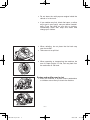
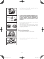
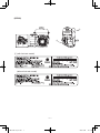
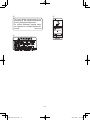
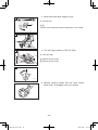
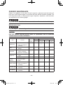
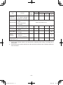
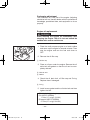
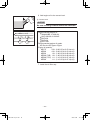
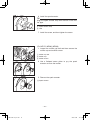
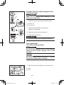
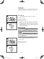
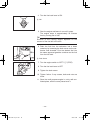
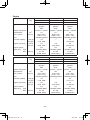
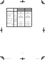
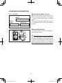
1
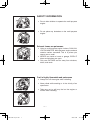
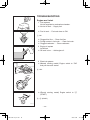
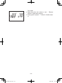
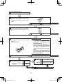
OWNER’S MANUAL Read this manual carefully before operating this machine. MZ175 MZ200 MZ250 MZ300 MZ360 PRINTED IN CHINA 2013.11×1 ! (E) 7VB-F8199-11_hyoshi.indd 1-2 LIT-19626-02-05 7VB-F8199-11 2013/11/27 15:04:17 Read this manual carefully before operating this machine. This manual should stay with this machine if it is sold. 7VB-F8199-11_hyoshi.indd 3-4 2013/11/27 15:04:17 INTRODUCTION Congratulations on your purchase of your new Yamaha. This manual will provide you with a good basic understanding of the operation and maintenance of this machine. If you have any questions regarding the operation or maintenance of your machine, please consult a Yamaha dealer. MZ175, MZ200, MZ250, MZ300, MZ360 OWNER’S MANUAL © 2013 by Yamaha Motor Corporation, U.S.A. 1st Edition, November 2013 All rights reserved. Any reprinting or unauthorized use without the written permission of Yamaha Motor Corporation, U.S.A. is expressly prohibited. Printed in China P/N LIT-19626-02-05 7VB-F8199-11_E0.indd 1 2013/12/04 10:13:17 IMPORTANT MANUAL INFORMATION Particularly important information is distinguished in this manual by the following notations. This is the safety alert symbol. It is used to alert you to potential personal injury hazards. Obey all safety messages that follow this symbol to avoid possible injury or death. WARNING A WARNING indicates a hazardous situation which, if not avoided, could result in death or serious injury. NOTICE A NOTICE indicates special precautions that must be taken to avoid damage to the machine or other property. TIP A TIP provides key information to make procedures easier or clearer. WARNING PLEASE READ AND UNDERSTAND THIS MANUAL COMPLETELY BEFORE OPERATING THE MACHINE. TIP 9 Yamaha continually seeks advancements in product design and quality. Therefore, while this manual contains the most current product information available at the time of printing, there may be minor discrepancies between your machine and this manual. If there is any question concerning this manual, please consult a Yamaha dealer. 9 This manual should be considered a permanent part of this machine and should remain with this machine when resold. * Product and specifications are subject to change without notice. 7VB-F8199-11_E0.indd 2 2013/12/04 10:13:22 CONTENTS SAFETY INFORMATION ....................... 1 Exhaust fumes are poisonous ............ 1 Fuel is highly flammable and poisonous ............................................ 1 Engine and muffler may be hot ........... 2 Electric shock prevention .................... 3 LOCATION OF IMPORTANT LABELS ................................................. 5 DESCRIPTION ..................................... 13 CONTROL FUNCTION ........................ 15 Engine switch .................................... 15 Oil warning light (Red) ...................... 15 Fuel tank cap (For models equipped with a Yamaha fuel tank) ... 16 Fuel cock lever .................................. 16 Recoil starter handle ......................... 16 Choke lever ....................................... 17 Throttle lever ..................................... 17 PREPARATION .................................... 18 Fuel (For models equipped with a Yamaha fuel tank) ............................. 18 Engine oil .......................................... 20 Connecting the battery (For models equipped with electric starter) ........... 21 PRE-OPERATION CHECK .................. 22 Pre-operation check .......................... 22 OPERATION ........................................ 23 Starting the engine............................ 24 Stopping the engine .......................... 27 High altitude operation ..................... 29 PERIODIC MAINTENANCE ................ 30 Maintenance chart ............................ 30 Spark plug inspection ....................... 32 Carburetor adjustment ...................... 33 Engine oil replacement ..................... 33 Air filter .............................................. 35 Spark arrester ................................... 36 Fuel cock ........................................... 39 7VB-F8199-11_E0.indd 3 Fuel tank filter (For models equipped with a Yamaha fuel tank) ... 40 Fuse replacement (For electric starting model) .............. 40 STORAGE ............................................ 42 Drain the fuel..................................... 42 Engine ............................................... 44 TROUBLESHOOTING ......................... 45 Engine won’t start ............................. 45 SPECIFICATIONS ................................ 51 Dimensions ....................................... 51 Engine ............................................... 52 CONSUMER INFORMATION .............. 55 Identification number records............ 55 Machine identification ....................... 55 EXHAUST EMISSION CONTROL SYSTEM AND COMPONENTS ........... 56 2013/12/04 10:13:22 SAFETY INFORMATION 9 Do not allow children to operate the multi-purpose engine. 9 Do not place any obstacles on the multi-purpose engine. Exhaust fumes are poisonous 9 Using a multi-purpose engine indoors CAN KILL YOU IN MINUTES. Multi-purpose engine exhaust contains carbon monoxide. This is a poison you cannot see or smell. 9 NEVER use inside a home or garage, EVEN IF doors and windows are open. 9 Only use OUTSIDE and far away from windows, doors, and vents. Fuel is highly flammable and poisonous 9 Always turn off the engine when refuelling. 9 Never refuel while smoking or in the vicinity of an open flame. 9 Take care not to spill any fuel on the engine or muffler when refueling. –1– 7VB-F8199-11_E0.indd 1 2013/12/04 10:13:22 9 Do not leave the multi-purpose engine inside the vehicle or in the trunk. 9 If you swallow any fuel, inhale fuel vapor, or allow any to get in your eye(s), see your doctor immediately. If any fuel spills on your skin or clothing, immediately wash with soap and water and change your clothes. 9 When refueling, do not place the fuel tank cap near the muffler. 9 Take care not to spill fuel. 9 When operating or transporting the machine, be sure it is kept upright. If it tilts, fuel may leak from the carburetor or fuel tank. Engine and muffler may be hot 9 Place the machine in a place where pedestrians or children are not likely to touch the machine. –2– 7VB-F8199-11_E0.indd 2 2013/12/04 10:13:24 9 Avoid placing any flammable materials near the exhaust outlet during operation. 9 In order to prevent overheating, be sure the equipment in which the multi-purpose engine is mounted allows adequate ventilation, and keep the equipment at least 1m (3 ft) from objects or other equipment. 9 Do not operate the engine with a dust cover or other objects covering it. 9 When covering the multi-purpose engine, be sure to do so only after the engine and muffler have completely cooled down. Electric shock prevention 9 Never operate the engine in rain or snow. 9 Never touch the machine with wet hands or electrical shock will occur. –3– 7VB-F8199-11_E0.indd 3 2013/12/04 10:13:26 –4– 7VB-F8199-11_E0.indd 4 2013/12/04 10:13:26 LOCATION OF IMPORTANT LABELS Please read the following labels carefully before operating this machine. TIP Maintain or replace safety and instruction labels, as necessary. (MZ175) 3 1 2 2 4 1 This spark ignition system meets all requirements of the Canadian Interference Causing Equipment Regulations. Ce système d’allumage respecte toutes les exigences sur le matériel brouilleur du Canada. 7CC-H2377-50 2 (with fuel tank model) (without fuel tank model) –5– 7VB-F8199-11_E0.indd 5 2013/12/04 10:13:28 3 7CN-F4162-50 4 –6– 7VB-F8199-11_E0.indd 6 2013/12/04 10:13:28 (MZ200) 3 4 2 1 1 (with fuel tank model) (without fuel tank model) –7– 7VB-F8199-11_E0.indd 7 2013/12/04 10:13:29 2 4 This spark ignition system meets all requirements of the Canadian Interference Causing Equipment Regulations. Ce système d’allumage respecte toutes les exigences sur le matériel brouilleur du Canada. 7CC-H2377-50 3 7CN-F4162-50 –8– 7VB-F8199-11_E0.indd 8 2013/12/04 10:13:30 (MZ250, MZ300 (7VB)) 3 2 1 4 1 (with fuel tank model) (without fuel tank model) –9– 7VB-F8199-11_E0.indd 9 2013/12/04 10:13:30 2 4 This spark ignition system meets all requirements of the Canadian Interference Causing Equipment Regulations. Ce système d’allumage respecte toutes les exigences sur le matériel brouilleur du Canada. 7CC-H2377-50 3 7CN-F4162-50 – 10 – 7VB-F8199-11_E0.indd 10 2013/12/04 10:13:30 (MZ300 (7CS), MZ360) 3 2 4 1 1 This spark ignition system meets all requirements of the Canadian Interference Causing Equipment Regulations. Ce système d’allumage respecte toutes les exigences sur le matériel brouilleur du Canada. 7CC-H2377-50 2 (with fuel tank model) (without fuel tank model) – 11 – 7VB-F8199-11_E0.indd 11 2013/12/04 10:13:32 3 4 7CN-F4162-50 – 12 – 7VB-F8199-11_E0.indd 12 2013/12/04 10:13:32 DESCRIPTION (MZ175, MZ200, MZ360) 0 1 2 9 3 8 4 5 7 6 (MZ250, MZ300 (7VB)) 0 1 2 9 3 4 8 5 7 6 – 13 – 7VB-F8199-11_E0.indd 13 2013/12/04 10:13:32 (MZ300 (7CS)) 0 1 2 3 q 9 w 8 4 5 7 6 y 1 Fuel tank cap (On models equipped with a Yamaha fuel tank) 2 Fuel tank (On models equipped with a Yamaha fuel tank) 3 Throttle lever 4 Recoil starter handle 5 Fuel cock lever 6 Fuel cock cup 7 Air filter case cover 8 Choke lever 9 Spark plug 0 Muffler q Oil warning light (Red) w Engine switch e Oil filler cap r Oil drain bolt t Carburetor y Fuel tank filter (On models equipped with a Yamaha fuel tank) q t w e r – 14 – 7VB-F8199-11_E0.indd 14 2013/12/04 10:13:32 CONTROL FUNCTION A Engine switch 2 The engine switch controls the ignition system. 1 “ON”/“7” (ON) 1 B 1 2 “OFF”/“5” (STOP) Ignition circuit is switched off. The engine will not run. 3 2 Ignition circuit is switched on. The engine can be started. 3 “6” (START) 763-119 Starting circuit is switched on. The starter motor starts and the engine can be started. After starting the engine, take your hand off the switch immediately. A Manual starting model B Electric starting model Oil warning light (Red) When the oil level falls below the lower level, the oil warning light comes on and then the engine stops automatically. Unless you refill with oil, the engine will not start again. TIP (Manual starting model) If the engine stalls or does not start, turn the engine switch to “ON” and then pull the recoil starter. If the oil warning light flickers for a few seconds, the engine oil is insufficient. Add oil and restart. (Electric starting model) If the engine stalls or does not start, turn the engine switch to “6” (START). If the oil warning light comes on, the engine oil is insufficient. Add oil and restart. – 15 – 7VB-F8199-11_E0.indd 15 2013/12/04 10:13:34 Fuel tank cap (For models equipped with a Yamaha fuel tank) Remove the fuel tank cap by turning it counterclockwise. (On models equipped with a Yamaha fuel tank) Fuel cock lever 2 The fuel cock supplies fuel from the fuel tank to the carburetor. The fuel cock has two positions. 2 1 ON With the lever in this position, fuel flows to the carburetor. Normal using is done with the lever in this position. 1 2 OFF With the lever in this position, fuel will not flow. Always turn the lever to this position when the engine is not running. 1 Recoil starter handle Used to start the engine. 1 Recoil starter handle NOTICE 9 Pull the recoil starter handle straight. 9 Return the recoil starter handle slowly. 9 Do not touch the recoil starter handle while the multi-purpose engine is operating. TIP Pull the recoil starter handle after turning the engine switch to “ON”. – 16 – 7VB-F8199-11_E0.indd 16 2013/12/04 10:13:34 Choke lever A Starting a cold engine requires a richer air-fuel mixture, which is supplied by the choke lever. 1 1 Choke lever ABC Functions and specification differs depending on the models. B 1 701-025c C 1 701-033b Throttle lever A Throttle lever controls the engine speed. 1 “ 1 2 ” Lever position to idle the engine. Decrease engine speed. 2 “ ” Increase engine speed. B AB Functions and specification differs depending on the models. 1 2 – 17 – 7VB-F8199-11_E0.indd 17 2013/12/04 10:13:36 PREPARATION Fuel (For models equipped with a Yamaha fuel tank) WARNING 9 Fuel is highly flammable and poisonous. Check “SAFETY INFORMATION” (See page 1) carefully before filling. 9 Do not fill the fuel above the red line, otherwise it may overflow when the fuel warms up and expands. 9 Wipe up any spilled fuel immediately. 9 After refueling, make sure the fuel tank cap is tightened securely. NOTICE Immediately wipe off spilled fuel with a clean, dry, soft cloth, since fuel may deteriorate painted surfaces or plastic parts. 1 Red line 1 1. Stop the engine. 2. Place the engine on a level surface. 3. Remove the fuel tank cap. 4. Check the fuel level. 5. If low, fill the tank with fuel. Do not fill past the red line as fuel may mix with the activated charcoal in the fuel tank cap and overflow. 2 3 TIP If filled beyond the red line, fuel may mix with the active charcoal located within the fuel tank cap and soil the surrounding areas. 2 Red line 3 Correct fuel level – 18 – 7VB-F8199-11_E0.indd 18 2013/12/04 10:13:37 Recommended fuel: Unleaded gasoline Fuel tank capacity: Total: MZ175 4.0 L MZ200 4.0 L MZ250 5.5 L MZ300 5.5 L MZ360 6.1 L (1.06 (1.06 (1.45 (1.45 (1.61 US US US US US gal, gal, gal, gal, gal, 0.88 0.88 1.21 1.21 1.34 Imp Imp Imp Imp Imp gal) gal) gal) gal) gal) Your Yamaha engine has been designed to use regular unleaded gasoline with a pump octane number ((R + M)/2) of 86 or higher, or research octane number of 91 or higher. NOTICE Use only unleaded gasoline. The use of leaded gasoline will cause severe damage to internal engine parts. – 19 – 7VB-F8199-11_E0.indd 19 2013/12/04 10:13:38 Engine oil NOTICE The multi-purpose engine has been shipped without engine oil. Do not start the engine until you have filled it with the sufficient engine oil. 1. Place the multi-purpose engine on a level surface. 2. Remove the oil filler cap. 1 Oil filler cap 1 3. Fill the specified amount of the recommended engine oil. 700-006 4. Check the oil level of the oil filler hole. 2 2 Correct level 5. Install the oil filler cap. 700-103 – 20 – 7VB-F8199-11_E0.indd 20 2013/12/04 10:13:38 0˚C 25˚C A YAMALUBE 4 (10W-40) D SAE 10W C SAE #20 32˚F B SAE #30 80˚F Recommended engine oil: A YAMALUBE 4 (10W-40), SAE 10W-30 or 10W-40 B SAE #30 C SAE #20 D SAE 10W Recommended engine oil grade: API Service SE type or higher Engine oil quantity: MZ175 0.6 L (0.63 US MZ200 0.6 L (0.63 US MZ250 1.0 L (1.06 US MZ300 (7VB) 1.0 L (1.06 US MZ300 (7CS) 1.1 L (1.16 US MZ360 1.1 L (1.16 US qt, qt, qt, qt, qt, qt, 0.53 0.53 0.88 0.88 0.97 0.97 Imp Imp Imp Imp Imp Imp qt) qt) qt) qt) qt) qt) Connecting the battery (For models equipped with electric starter) 1 2 764-004 Recommended battery capacity is 12 V/26 Ah or more. Use battery lead wires with cross section of at least 8 mm (0.31 in) square. 1 Connect the battery positive terminal to the starter switch. 2 Ground the battery negative terminal to the engine mounting bolt. – 21 – 7VB-F8199-11_E0.indd 21 2013/12/04 10:13:39 PRE-OPERATION CHECK WARNING If any item in the Pre-operation check is not working properly, have it inspected and repaired before operating the multi-purpose engine. The condition of a multi-purpose engine is the owner’s responsibility. Vital components can start to deteriorate quickly and unexpectedly, even if the multi-purpose engine is unused. TIP Pre-operation checks should be made each time the multi-purpose engine is used. Pre-operation check Fuel (See page 18 for Yamaha fuel tank instructions) 9 Check fuel level in fuel tank. 9 Refuel if necessary. Fuel line 9 Check fuel hose for cracks or damage. 9 Replace if necessary. Engine oil (See page 20) 9 Check oil level in engine. 9 If necessary, add recommended oil to correct level. 9 Check multi-purpose engine for oil leakage. The point where abnormality was recognized by use 9 Check operation. 9 If necessary, consult a Yamaha dealer. – 22 – 7VB-F8199-11_E0.indd 22 2013/12/04 10:13:39 OPERATION WARNING Never operate the engine in a closed area or it may cause unconsciousness and death within a short time. Operate the engine in a well ventilated area. NOTICE The multi-purpose engine has been shipped without engine oil. Do not start the engine until you have filled it with the sufficient engine oil. – 23 – 7VB-F8199-11_E0.indd 23 2013/12/04 10:13:39 Starting the engine 1. Turn the fuel cock lever to ON. 1 ON 1 2. Pull the choke lever fully out. A Turn the choke lever to “1”. B C A 2 Choke lever ABC Functions and specification differs depending on the models. 2 B 2 TIP The choke is not required to start a warm engine. When starting the warm engine, put the choke lever to the original position. 701-025c C 2 701-033 – 24 – 7VB-F8199-11_E0.indd 24 2013/12/04 10:13:40 3. Move the throttle lever slightly to right. A 3 Throttle lever 3 AB Functions and specification differs depending on the models. B 3 4. Turn the engine switch to “ON”/“7” (ON). A 4 “ON”/“7” (ON) 4 B A Manual starting model B Electric starting model 4 763-127h 5. (Manual starting model) Pull the recoil starter slowly until it is engaged, then pull it briskly. – 25 – 7VB-F8199-11_E0.indd 25 2013/12/04 10:13:41 5 6. (Electric starting model) Turn the engine switch to “6” (START). Take your hand off the switch immediately after the engine starts. 5 “6” (START) 763-120a NOTICE If the engine fails to start, release the switch, wait a few seconds, then try again. Each attempt should be as short as possible to preserve the battery. Do not crank the engine more than 5 seconds on any one attempt. 7. After the engine starts, warm up the engine enough so that the engine does not stop when the choke lever is returned to the original position. A 6 Original position 6 ABC Functions and specification differs depending on the models. B 6 701-025c C 6 701-033a – 26 – 7VB-F8199-11_E0.indd 26 2013/12/04 10:13:43 8. Set the throttle lever in desired position. A 7 “ 8 “ 7 8 ”: Decrease engine speed ”: Increase engine speed AB Functions and specification differs depending on the models. B 7 8 Stopping the engine A 1. Move the throttle lever fully to the left. 1 Throttle lever AB Functions and specification differs depending on the models. B 1 2. Turn the engine switch to “OFF”/“5” (STOP). A 2 2 “OFF”/“5” (STOP) A Manual starting model B Electric starting model B 2 763-120b – 27 – 7VB-F8199-11_E0.indd 27 2013/12/04 10:13:45 3. Turn the fuel cock lever to OFF. 3 OFF 3 3 – 28 – 7VB-F8199-11_E0.indd 28 2013/12/04 10:13:46 High altitude operation This engine may require a high altitude carburetor kit to ensure correct engine operation at altitudes above 4000 ft. (1219 meters). If you operate your engine at altitudes above 4000 ft. (1219 meters) consistently, have your local Yamaha dealer perform the necessary carburetor modification. This engine should be operated in its original configuration below 4000 ft. (1219 meters) as damage may occur if high altitude carburetor kit is installed and operated below 4000 ft. (1219 meters). – 29 – 7VB-F8199-11_E0.indd 29 2013/12/04 10:13:47 PERIODIC MAINTENANCE Safety is an obligation of the owner. Periodic inspection, adjustment and lubrication will keep your multi-purpose engine in the safest and most efficient condition possible. The most important points of multi-purpose engine inspection, adjustment, and lubrication are explained on the following pages. WARNING If you are not familiar with maintenance work, have a Yamaha dealer do it for you. Maintenance chart WARNING Stop the engine before starting maintenance work. NOTICE Use only Yamaha specified genuine parts for replacement. Ask an authorized Yamaha dealer for further information. Item Routine Initial Every Preoperation 1 month 3 months 6 months 12 months check or 20 Hrs or 50 Hrs or 100 Hrs or 300 Hrs • Check condition. Spark plug • Clean and replace if necessary. • Check fuel level and leakage. • Check fuel hose for cracks or damage. Fuel Fuel hose 1 1 1 • Replace if necessary. • Check oil level in engine. Engine oil 1 • Replace. 1 • Check condition. Air filter element 1 1 (*1) • Clean. • Check condition. Spark arrester • Clean and replace if necessary. • Clean and replace if Fuel tank filter necessary. • Clean and replace if Fuel strainer necessary. 1 1 1 – 30 – 7VB-F8199-11_E0.indd 30 2013/12/04 10:13:47 Item Routine Crankcase breather hose Cylinder head Valve clearance Idle speed Recoil starter Fittings / fasteners Initial Every Preoperation 1 month 3 months 6 months 12 months check or 20 Hrs or 50 Hrs or 100 Hrs or 300 Hrs • Check breather hose for cracks or damage. 1 • Replace if necessary. • Decarbonize cylinder head. • More frequently if necessary. • Check and adjust when engine is cold. • Check and adjust idle speed. • Check recoil starter for damage. • Check all fittings and fasteners. After every 500 Hrs. () • Correct if necessary. The point where abnormality was recognized by use. 1 *1·····The air filter element needs to be cleaned more frequently when using in unusually wet or dusty areas. ·····Since these items require special tools, data and technical skills, have a Yamaha dealer perform the service. – 31 – 7VB-F8199-11_E0.indd 31 2013/12/04 10:13:47 Spark plug inspection A The spark plug is an important engine component, which should be checked periodically. 1. Remove the spark plug cap and the spark plug. 2. Check for discoloration and remove the carbon. The porcelain insulator around the center electrode of spark plug should be a medium-to-light tan color. B A MZ175, MZ200 B Except for MZ175, MZ200 3. Check the spark plug type and gap. a Spark plug gap Standard spark plug: BPR4ES (NGK) Spark plug gap: 0.7–0.8 mm (0.028–0.031 in) a TIP The spark plug gap should be measured with a wire thickness gauge and, if necessary, adjusted to specification. 4. Install the spark plug and then tighten it. Spark plug tightening torque: 20 Nm (2.0 m·kgf, 14 ft·lbf) TIP If a torque wrench is not available when installing a spark plug, a good estimate of the correct torque is 1/4–1/2 turn past finger tight. However, the spark plug should be tightened to the specified torque as soon as possible. 5. Install the spark plug cap. – 32 – 7VB-F8199-11_E0.indd 32 2013/12/04 10:13:49 Carburetor adjustment The carburetor is a vital part of the engine. Adjusting should be left to a Yamaha dealer with the professional knowledge, specialized data, and equipment to do so properly. Engine oil replacement WARNING Avoid draining the engine oil immediately after stopping the engine. The oil is hot and should be handled with care to avoid burns. 1 2 1. Place the multi-purpose engine on a level surface and warm up the engine for several minutes. Then stop the engine and turn the fuel cock lever to OFF. 4 3 2. Remove the oil filler cap. 1 Oil filler cap 3. Place an oil pan under the engine. Remove the oil drain bolt and gasket so that the oil can be completely drained. 2 Oil drain bolt 3 Gasket 4. Check the oil drain bolt, oil filler cap and O-ring. Replace them if damaged. 4 O-ring 5. Install a new gasket and the oil drain bolt and then tighten the bolt. Oil drain bolt tightening torque: (For MZ175, MZ200) 17 Nm (1.7 m·kgf, 12 ft·lbf) (Except for MZ175, MZ200) 27 Nm (2.7 m·kgf, 20 ft·lbf) – 33 – 7VB-F8199-11_E0.indd 33 2013/12/04 10:13:49 6. Add engine oil to the correct level. 5 Correct Level 5 NOTICE Be sure no foreign material enters the crankcase. 700-006a 0˚C 25˚C A YAMALUBE 4 (10W-40) D SAE 10W C SAE #20 32˚F B SAE #30 80˚F Recommended engine oil: A YAMALUBE 4 (10W-40), SAE 10W-30 or 10W-40 B SAE #30 C SAE #20 D SAE 10W Recommended engine oil grade: API Service SE type or higher Engine oil quantity: MZ175 0.6 L (0.63 US MZ200 0.6 L (0.63 US MZ250 1.0 L (1.06 US MZ300 (7VB) 1.0 L (1.06 US MZ300 (7CS) 1.1 L (1.16 US MZ360 1.1 L (1.16 US qt, qt, qt, qt, qt, qt, 0.53 0.53 0.88 0.88 0.97 0.97 Imp Imp Imp Imp Imp Imp qt) qt) qt) qt) qt) qt) 7. Install the oil filler cap. – 34 – 7VB-F8199-11_E0.indd 34 2013/12/04 10:13:50 A 2 3 1 Air filter 1. Remove the screws, and then remove the air filter case cover. 1 Screw 2 Air filter case cover 2. Remove the foam element. 3 Foam element 3. Wash the foam element in solvent and dry it. WARNING Never use solvent while smoking or in the vicinity of an open flame. 4. Oil the foam element and squeeze out excess oil. The foam element should be wet but not dripping. Recommended oil: Foam-air-filter oil or engine oil (See page 34) B 2 3 NOTICE Do not wring out the foam element when squeezing it. This could cause it to tear. 1 5. Insert the foam element into the air filter case. TIP Be sure the foam element sealing surface matches the air filter case so there is no air leak. NOTICE The engine should never run without the foam element; excessive piston and cylinder wear may result. 6. Install the air filter case cover and tighten the screws. A MZ175, MZ200, MZ300 (7CS), MZ360 B MZ250, MZ300 (7VB) – 35 – 7VB-F8199-11_E0.indd 35 2013/12/04 10:13:51 Spark arrester WARNING The engine and muffler will be very hot after the engine has been run. Avoid touching the engine and muffler while they are still hot with any part of your body or clothing during inspection or repair. 1 (For MZ250, MZ300 (7VB)) 1. Remove the screw. 1 Screw 2. Use a flathead screw driver to pry the spark arrester out from the muffler. 3. Remove the spark arrester. 2 2 Spark arrester 4. Remove the carbon deposits on the spark arrester using a wire brush. NOTICE When cleaning, use the wire brush lightly to avoid damaging or scratching of the spark arrester. 711-003a 5. Check the spark arrester. Replace it if damaged. – 36 – 7VB-F8199-11_E0.indd 36 2013/12/04 10:13:52 6. Install the spark arrester. TIP Align the spark arrester lump with the hole in the muffler pipe. 4 3 3 Spark arrester lump 4 Hole 7. Install the screw, and then tighten the screw. (For MZ175, MZ200, MZ360) 1. Loosen the muffler cap bolt and then remove the muffler cap and muffler screen. 2 1 1 Muffler cap bolt 2 Muffler cap 3 Muffler screen 3 2. Use a flathead screw driver to pry the spark arrester out from the muffler. 3. Remove the spark arrester. 4 4 Spark arrester – 37 – 7VB-F8199-11_E0.indd 37 2013/12/04 10:13:54 4. Remove the carbon deposits on the muffler cap, muffler screen and spark arrester using a wire brush. NOTICE When cleaning, use the wire brush lightly to avoid damaging or scratching of the muffler screen and spark arrester. 5. Check the muffler screen and spark arrester. Replace them if damaged. 6 5 6. Install the spark arrester. TIP Align the spark arrester lump with the hole in the muffler pipe. 5 Spark arrester lump 6 Hole 3 2 7. Install the muffler screen to the muffler cap, then install the muffler cap to the muffler. 2 Muffler cap 3 Muffler screen TIP Install the muffler cap until it contacts with the projection on the muffler. 7 7 Projection 2 8 8. Install the muffler band, then tighten the muffler cap bolt. 8 Muffler band Muffler cap bolt tightening torque: 3.5 Nm (0.35 m·kgf, 2.5 ft·lbf) – 38 – 7VB-F8199-11_E0.indd 38 2013/12/04 10:13:55 Fuel cock WARNING 1 1 Never use the gasoline while smoking or in the vicinity of an open flame. 1. Stop the engine. 2. Turn the fuel cock lever to OFF. 1 OFF 3. Remove the fuel cock cup, gasket and fuel strainer. 2 Fuel cock cup 3 Gasket 4 Fuel strainer 4 3 2 4. Clean the cup and fuel strainer with gasoline and wipe it off. 5. Check the gasket. Replace it if damaged. 6. Install the fuel strainer, gasket and fuel cock cup. WARNING Be sure the fuel cock cup is tightened securely. – 39 – 7VB-F8199-11_E0.indd 39 2013/12/04 10:13:56 Fuel tank filter (For models equipped with a Yamaha fuel tank) 1 WARNING Never use the gasoline while smoking or in the vicinity of an open flame. 2 1. Remove the fuel tank cap and fuel tank filter. 1 Fuel tank cap 2 Fuel tank filter 2. Clean the fuel tank filter with gasoline. Replace it if damaged. 3. Wipe the fuel tank filter and insert it. 4. Install the fuel tank cap. WARNING Be sure the fuel tank cap is tightened securely. Fuse replacement (For electric starting model) WARNING Be sure to use specified fuse. A wrong fuse will cause electrical system damage and A FIRE HAZARD. NOTICE Be sure the engine switch is turned to “5” (STOP) to prevent accidental short circuiting. 1. Remove the screws and then remove the cover. 1 Screw 2 Cover 1 2 779-041 – 40 – 7VB-F8199-11_E0.indd 40 2013/12/04 10:13:57 2. Replace the blown fuse with one of proper amperage. 3 Specified fuse: 10 A 779-042 TIP If the fuse immediately blows again, consult a Yamaha dealer. 3 Fuse 3. Install the cover and then tighten the screws. – 41 – 7VB-F8199-11_E0.indd 41 2013/12/04 10:13:58 STORAGE Long term storage of your machine will require some preventive procedures to guard against deterioration. Drain the fuel A 1. Turn the engine switch to “OFF”/“5” (STOP). 1 1 “OFF”/“5” (STOP) A Manual starting model B Electric starting model 2. Remove the fuel tank cap and fuel tank filter. Extract the fuel from the fuel tank into an approved gasoline container using a commercially available hand siphon. Then, install the fuel tank filter and fuel tank cap. B 1 WARNING 763-120b Fuel is highly flammable and poisonous. Check “SAFETY INFORMATION” (See page 1) carefully. NOTICE Immediately wipe off spilled fuel with a clean, dry, soft cloth, since fuel may deteriorate painted surfaces or plastic parts. 3. Turn the engine switch to “ON”/“7” (ON). A 2 “ON”/“7” (ON) 2 B A Manual starting model B Electric starting model 2 763-127h – 42 – 7VB-F8199-11_E0.indd 42 2013/12/04 10:13:59 4. Turn the fuel cock lever to ON. 3 ON 3 5. Start the engine and leave it run until it stops. The engine stops in approximately 20 minutes time by running out of fuel. TIP Duration of the running engine depends on the amount of the fuel left in the tank. 6. Drain the fuel from the carburetor into a clean container by loosening the drain screw on the carburetor float chamber. Pour the drained fuel into the same approved gasoline container as the fuel from the fuel tank. 4 4 Drain Screw 7. Turn the engine switch to “OFF”/“5” (STOP). 8. Turn the fuel cock lever to OFF. 9. Tighten the drain screw. 10. Tighten further if any screws, bolts and nuts are loose. 11. Store the multi-purpose engine in a dry, well-ventilated place, with the cover placed over it. – 43 – 7VB-F8199-11_E0.indd 43 2013/12/04 10:13:59 Engine Perform the following steps to protect the cylinder, piston ring, etc. from corrosion. 1. Remove the spark plug, pour about one tablespoon of engine oil (See page 34) into the spark plug hole and reinstall the spark plug. Recoil start the engine by turning over several times (with ignition off) to coat the cylinder walls with oil. 2. Pull the recoil starter until you feel compression. Then stop pulling. (This prevents the cylinder and valves from rusting). 3. Clean exterior of the multi-purpose engine and apply a rust inhibitor. 4. Store the multi-purpose engine in a dry, well-ventilated place, with the cover placed over it. 5. The multi-purpose engine must remain in a vertical position when stored, carried or operated. – 44 – 7VB-F8199-11_E0.indd 44 2013/12/04 10:13:59 TROUBLESHOOTING Engine won’t start 1. Fuel systems No fuel supplied to combustion chamber. 2 No fuel in tank .... Supply fuel. 2 Fuel in tank .... Fuel cock lever to ON. 1 ON 2 Clogged fuel line .... Clean fuel line. 2 Foreign matter in fuel cock .... Clean fuel cock. 2 Clogged carburetor .... Clean carburetor. 1 2. Engine oil system Insufficient 2 Oil level is low .... Add engine oil. 700-006 3. Electrical systems 2 (Manual starting model) Engine switch to “ON” and pull the recoil starter. 2 “ON” 2 2 2 (Electric starting model) Engine switch to “6” (START). 2 “6” (START) 763-120a – 45 – 7VB-F8199-11_E0.indd 45 2013/12/04 10:14:00 Poor spark 2 Spark plug dirty with carbon or wet .... Remove carbon or wipe spark plug dry. 2 Faulty ignition system .... Consult a Yamaha dealer. – 46 – 7VB-F8199-11_E0.indd 46 2013/12/04 10:14:00 (Manual starting model) A ENGINE DOES NOT START B Turn the engine switch to “ON”, then pull the recoil starter and check if the oil warning light flickers. E C H Does not flicker D Check engine oil level. Flickers Pull the recoil starter and check the spark plug for spark strength. (See “WARNING”) F OK Consult a Yamaha dealer. G Level low Add engine oil. WARNING 9 To prevent FIRE HAZARDS be sure fuel is not present in the spark plug area. 9 To prevent FIRE HAZARDS be sure to place the spark plug as far away as possible from the spark plug hole and carburetor area. 9 To prevent ELECTRIC SHOCK do not hold spark plug lead with hand while testing. I OK J K Check the spark plug. 9 Type: BPR4ES 9 Gap: 0.7–0.8 mm (0.028–0.031 in) L Incorrect Replace or adjust gap. Does not spark Q N M OK Clean the spark plug. Check the following. 9 Fuel line clogging 9 Air filter element clogging. O Clogged P OK T Clean or replace. R OK S Engine does not start. Consult a Yamaha dealer. – 47 – 7VB-F8199-11_E0.indd 47 2013/12/04 10:14:00 – 48 – 7VB-F8199-11_E0.indd 48 2013/12/04 10:14:00 (Electric starting model) A ENGINE DOES NOT START B Turn the engine switch to “7” (ON), then turn the engine switch to “6” (START). And check if the starter motor cranks. C F Cranks D Turn the engine switch to “6” (START), and check if the oil warning light comes on. Does not crank P34-1.art G Does not come on H L Turn the engine switch to “6” (START) and check the spark plug for spark strength. (See “WARNING”). OK M WARNING P34-2.art 9 To prevent FIRE HAZARDS be sure fuel is not present in the spark plug area. 9 To prevent FIRE HAZARDS be sure to place the spark plug as far away as possible from the spark plug hole and carburetor area. 9 To prevent ELECTRIC SHOCK do not hold spark plug lead with hand while testing. N Does not spark. U R Check the following 9 Fuel cock clogging 9 Air cleaner element clogging. S Clogged T OK Comes on X Clean or replace V OK W Engine does not start. Consult a Yamaha dealer. – 49 – 7VB-F8199-11_E0.indd 49 2013/12/04 10:14:01 E Faulty battery and/or starter motor. Consult a Yamaha dealer. I Check engine oil level. J OK Consult a Yamaha dealer. O P K Level low Add engine oil. Check the spark plug. 9 Type: BPR4ES 9 Gap: 0.7–0.8 mm (0.028–0.031 in) Incorrect Replace or adjust gap. Q OK Clean the spark plug. – 50 – 7VB-F8199-11_E0.indd 50 2013/12/04 10:14:01 SPECIFICATIONS Dimensions Unit Overall length Overall width Overall height Dry weight mm (in) mm (in) mm (in) kg (lb) Unit Overall length Overall width Overall height Dry weight mm (in) mm (in) mm (in) kg (lb) Unit Overall length Overall width Overall height Dry weight mm (in) mm (in) mm (in) kg (lb) Unit Overall length Overall width Overall height Dry weight mm (in) mm (in) mm (in) kg (lb) Unit Overall length Overall width Overall height Dry weight mm (in) mm (in) mm (in) kg (lb) MZ175 MZ175 MZ175 7CN 7CN 7CP With fuel tank model Without fuel tank model With fuel tank model 326 (12.83) 337 (13.27) 317 (12.48) 352 (13.86) 352 (13.86) 361 (14.21) 407 (16.02) 238 (9.37) 407 (16.02) 13–20 (29–44) 13–20 (29–44) 13–20 (29–44) MZ200 MZ200 MZ250 7DH 7DH 7KB With fuel tank model Without fuel tank model With fuel tank model 326 (12.83) 337 (13.27) 387 (15.24) 352 (13.86) 352 (13.86) 426 (16.77) 407 (16.02) 238 (9.37) 464 (18.27) 13–20 (29–44) 13–20 (29–44) 20–27 (44–60) MZ250 MZ300 MZ300 7KB 7VB 7VB Without fuel tank model With fuel tank model Without fuel tank model 404 (15.91) 387 (15.24) 404 (15.91) 416 (16.38) 426 (16.77) 416 (16.38) 294.5 (11.59) 464 (18.27) 294.5 (11.59) 20–27 (44–60) 20–27 (44–60) 20–27 (44–60) MZ300 MZ360 MZ360 7CS 7CT 7CT Without fuel tank model With fuel tank model Without fuel tank model 443 (17.44) 425 (16.73) 443 (17.44) 470 (18.50) 451 (17.76) 452 (17.80) 327 (12.87) 485 (19.09) 306 (12.05) 31–40 (68–88) 31–40 (68–88) 31–40 (68–88) MZ360 MZ360 7BY 7CN Without fuel tank model Without fuel tank model 381 (15.00) 443 (17.44) 436 (17.17) 470 (18.50) 319 (12.56) 327 (12.87) 31–40 (68–88) 31–40 (68–88) – 51 – 7VB-F8199-11_E0.indd 51 2013/12/04 10:14:01 Engine MZ175 MZ175 7CN 7CN With fuel tank model Without fuel tank model Type Air cooled 4-stroke Air cooled 4-stroke gasoline gasoline OHV OHV Cylinder arrangement Inclined, 1 cylinder Inclined, 1 cylinder Displacement cm3 171 171 Bore × stroke mm (in) 66.0 × 50.0 66.0 × 50.0 (2.60 × 1.97) (2.60 × 1.97) Fuel Unleaded gasoline Unleaded gasoline Fuel tank capacity L (US gal, 4.0 — Imp gal) (1.06, 0.88) Engine oil quantity L (US qt, 0.6 0.6 Imp qt) (0.63, 0.53) (0.63, 0.53) Ignition system TCI TCI Spark plug: Type BPR4ES (NGK) BPR4ES (NGK) Gap mm (in) 0.7–0.8 0.7–0.8 (0.028–0.031) (0.028–0.031) MZ175 7CP With fuel tank model Air cooled 4-stroke gasoline OHV Inclined, 1 cylinder 171 66.0 × 50.0 (2.60 × 1.97) Unleaded gasoline 4.0 (1.06, 0.88) 0.6 (0.63, 0.53) TCI BPR4ES (NGK) 0.7–0.8 (0.028–0.031) MZ200 MZ200 7DH 7DH With fuel tank model Without fuel tank model Type Air cooled 4-stroke Air cooled 4-stroke gasoline gasoline OHV OHV Cylinder arrangement Inclined, 1 cylinder Inclined, 1 cylinder Displacement cm3 192 192 Bore × stroke mm (in) 70.0 × 50.0 70.0 × 50.0 (2.76 × 1.97) (2.76 × 1.97) Fuel Unleaded gasoline Unleaded gasoline Fuel tank capacity L (US gal, 4.0 — Imp gal) (1.06, 0.88) Engine oil quantity L (US qt, 0.6 0.6 Imp qt) (0.63, 0.53) (0.63, 0.53) Ignition system TCI TCI Spark plug: Type BPR4ES (NGK) BPR4ES (NGK) Gap mm (in) 0.7–0.8 0.7–0.8 (0.028–0.031) (0.028–0.031) MZ250 7KB With fuel tank model Air cooled 4-stroke gasoline OHV Inclined, 1 cylinder 253 74.0 × 59.0 (2.91 × 2.32) Unleaded gasoline 5.5 (1.45, 1.21) 1.0 (1.06, 0.88) TCI BPR4ES (NGK) 0.7–0.8 (0.028–0.031) Unit Unit – 52 – 7VB-F8199-11_E0.indd 52 2013/12/04 10:14:01 MZ250 7KB Without fuel tank model Type Air cooled 4-stroke gasoline OHV Cylinder arrangement Inclined, 1 cylinder Displacement cm3 253 Bore × stroke mm (in) 74.0 × 59.0 (2.91 × 2.32) Fuel Unleaded gasoline Fuel tank capacity L (US gal, — Imp gal) Engine oil quantity L (US qt, 1.0 Imp qt) (1.06, 0.88) Ignition system TCI Spark plug: Type BPR4ES (NGK) Gap mm (in) 0.7–0.8 (0.028–0.031) MZ300 MZ300 7VB 7VB With fuel tank model Without fuel tank model Air cooled 4-stroke Air cooled 4-stroke gasoline gasoline OHV OHV Inclined, 1 cylinder Inclined, 1 cylinder 296 296 80.0 × 59.0 80.0 × 59.0 (3.15 × 2.32) (3.15 × 2.32) Unleaded gasoline Unleaded gasoline 5.5 — (1.45, 1.21) 1.0 1.0 (1.06, 0.88) (1.06, 0.88) TCI TCI BPR4ES (NGK) BPR4ES (NGK) 0.7–0.8 0.7–0.8 (0.028–0.031) (0.028–0.031) MZ300 7CS Without fuel tank model Type Air cooled 4-stroke gasoline OHV Cylinder arrangement Inclined, 1 cylinder Displacement cm3 301 Bore × stroke mm (in) 78.0 × 63.0 (3.07 × 2.48) Fuel Unleaded gasoline Fuel tank capacity L (US gal, — Imp gal) Engine oil quantity L (US qt, 1.1 Imp qt) (1.16, 0.97) Ignition system TCI Spark plug: Type BPR4ES (NGK) Gap mm (in) 0.7–0.8 (0.028–0.031) MZ360 MZ360 7CT 7CT With fuel tank model Without fuel tank model Air cooled 4-stroke Air cooled 4-stroke gasoline gasoline OHV OHV Inclined, 1 cylinder Inclined, 1 cylinder 357 357 85.0 × 63.0 85.0 × 63.0 (3.35 × 2.48) (3.35 × 2.48) Unleaded gasoline Unleaded gasoline 6.1 — (1.61, 1.34) 1.1 1.1 (1.16, 0.97) (1.16, 0.97) TCI TCI BPR4ES (NGK) BPR4ES (NGK) 0.7–0.8 0.7–0.8 (0.028–0.031) (0.028–0.031) Unit Unit – 53 – 7VB-F8199-11_E0.indd 53 2013/12/04 10:14:01 MZ360 7BY Without fuel tank model Type Air cooled 4-stroke gasoline OHV Cylinder arrangement Inclined, 1 cylinder Displacement cm3 357 Bore × stroke mm (in) 85.0 × 63.0 (3.35 × 2.48) Fuel Unleaded gasoline Fuel tank capacity L (US gal, — Imp gal) Engine oil quantity L (US qt, 1.1 Imp qt) (1.16, 0.97) Ignition system TCI Spark plug: Type BPR4ES (NGK) Gap mm (in) 0.7–0.8 (0.028–0.031) Unit MZ360 7CN Without fuel tank model Air cooled 4-stroke gasoline OHV Inclined, 1 cylinder 357 85.0 × 63.0 (3.35 × 2.48) Unleaded gasoline — 1.1 (1.16, 0.97) TCI BPR4ES (NGK) 0.7–0.8 (0.028–0.031) – 54 – 7VB-F8199-11_E0.indd 54 2013/12/04 10:14:01 CONSUMER INFORMATION Identification number records PRI-I.D. NUMBER: MODEL PRI-I.D. CODE SERIAL No. Record your Primary I.D., and serial numbers in the spaces provided, to assist you in ordering spare parts from a Yamaha dealer. Also record and keep these I.D. numbers in a separate place in case your machine is stolen. Machine identification The machine serial number is stamped in the location as shown. TIP The first three digits of these numbers are for model identification; the remaining digits are the unit production number. Keep a record of these numbers for reference when ordering parts from a Yamaha dealer. – 55 – 7VB-F8199-11_E0.indd 55 2013/12/04 10:14:01 EXHAUST EMISSION CONTROL SYSTEM AND COMPONENTS Item Acronym 9 CARB. ASSY., LH. & JT., ....................... CARB (Carburetor) CARBURETOR2 9 T.C.I. MAGNETO ASSY. & ..................... EI (Electronic Ignition) PLUG, SPARK 9 CRANKCASE1 & HEAD, ....................... PCV (Positive Crankcase CYLINDER1 Ventilation) 9 AIR FILTER ASSY. . ................................ ACL (Air Cleaner) 9 MUFF., 2, CAP, NET, WIRE2 & ARRESTER, SPARK The above items and the corresponding acronyms are provided in accordance with U.S. EPA REGULATIONS FOR NEW NONROAD SPARK-IGNITION NONHANDHELD ENGINES and the CALIFORNIA REGULATIONS FOR 1995 AND LATER SMALL OFFROAD ENGINES. The acronyms conform to the latest version of the SAE’s recommended practice document J1930, “Diagnostic Acronyms, Terms, and Definitions For Electrical/Electronic System”. It is recommended that these items be serviced by a Yamaha dealer. – 56 – 7VB-F8199-11_E0.indd 56 2013/12/04 10:14:01 7VB-F8199-11_E0.indd 57 2013/12/04 10:14:01