1
How to Use this Manual
This manual describes your new notebook and contains all the information you
need to set up and use the notebook. Whether you are a new or an experienced
user, you will benefit more from this manual if you are familiar with its
organization. This manual describes the PC-9300T and PC-9300D notebooks.
Unless otherwise specified, the descriptions in this manual apply to both models.
Illustrations are based on the PC-9300T notebook.
The manual is divided into five chapters, plus appendixes.
Chapter 1 Introducing the System gives a general introduction to the notebook,
explaining the main functions such as the keyboard, the indicator lamps, etc.
Chapter 2 Using the Notebook for the First Time gives the basic steps for
getting your notebook up and running.
Chapter 3 Setup Utility shows how you can make changes to the operation and
power management of the notebook by using the Setup utility.
Chapter 4 Using the Notebook describes how to carry out typical operations on
the notebook such as using the disk drives, using the GlidePoint, changing the
display, and so on.
Chapter 5 System Expansion describes how you can use the notebook’s built-in
ports and connectors to add peripheral components to your system.
Appendixes provide advice on the routine care and maintenance of the notebook,
a guide to troubleshooting problems that may arise in the use of the notebook, and
detailed specifications on your notebook and the built-in ports. For your
convenience, an index is provided at the end of this manual.
In addition to this manual, you may want to consult the Windows 95 manual, and the
manuals for your software applications. The Sharp Online Manual, accessible from
the Windows 95 Start Menu, will also help your computing.
i
Manual Conventions
This manual uses different text styles to help identify different operations and
functions of your notebook.
Keyboard Keys
When referring to specific keys on the keyboard, the key label appears in boldface
as shown below:
Press Enter to execute the installation.
When referring to a combination of keys that are pressed simultaneously, the key
labels are separated by a plus sign (+) as shown below:
Pressing Ctrl + Alt + Del lets you reset your notebook.
Sample Entries/Prompts/Screens
This manual contains sample screens that might appear during the operation of
your notebook, including prompts (text generated by the system) and entries (text
you type on the keyboard). These are printed in a typeface like the one below:
Re-enter your password for verification.
In the following case, press the Enter key after you type the command.
C:\>FORMAT A: Enter
The screens reproduced in this manual may differ slightly from the screens you
see on your notebook.
File Names
References to commands, utilities, device drivers, directory and file names in this
manual are printed in upper case.
The CONFIG.SYS file contains the specifications for configuring the
system.
ii
Section Titles/Possible Parameters
In a section of text, words which represent selectable parameters, or words which
refer to other sections in the manual are italicized.
Select Disabled to disable the floppy disk drive. See the section Making
Changes in the Main Page for more details.
Notes and Cautions
Icons and italic text are used for notes and cautions, to make important
information stand out.
Notes: Notes give you helpful hints or suggestions on ways of performing
certain operations.
Cautions: Cautions alert you that damage to equipment or loss of data
may occur if certain procedures are not followed carefully.
iii
Recording Information
For future reference, please record the following information in the spaces
provided below.
Model Number:
Serial Number:
BIOS Version
Number:
Date of purchase:
Dealer’s Name:
Place of purchase:
Password:
The serial number is printed on a sticker located on the bottom of the notebook.
You will see the BIOS Version number on the LCD screen when you turn on the
notebook.
iv
Unpacking the Notebook
Please check that all the accessories listed below have been included with your
computer.
Main Unit
•
•
•
•
•
•
•
•
•
AC Adapter
Power Cord
Modem Cable (US
& Canada only)
(PC-9300T only)
Windows 95 Manual Pack (CD-ROM and Manual)
Backup CD-ROM
CD-ROM Setup Boot Disk
Operation Manual
Re-installation Instructions
TranXit Quick Reference Guide
Sharp Import/Export User’s Guide
SuperVoice Manual (US & Canada only) (PC-9300T only)
AT Command Reference Manual (US & Canada only) (PC-9300T only)
In addition, your notebook package includes various software license agreements,
warranty cards, and so on. If any of the listed accessories are missing, or if the
main unit or accessories are damaged, please consult your dealer (or in case of
US, a Sharp Customer Service Center at 1-800-BE-SHARP).
Note: Only the PC-9300T is equipped with a fax/modem. The fax/modem
is available only in the USA and Canada.
v
About the System Documentation
The manuals included with your notebook are used as follows:
Operation Manual (this manual)
This manual gives instructions on how to operate your computer successfully. It
also explains how you can use some of the software that is pre-installed on the
hard disk drive, and how you can add extra devices to your notebook, either
internally or externally.
Re-installation Instructions
This manual explains how to re-install the Windows 95 operating system and the
utility programs that are pre-installed on your notebook's hard disk drive.
Windows 95 Manual & License
This manual explains the basic procedures for using Windows 95.
TranXit Quick Reference Guide
This guide is an introduction to the TranXit infrared communications program
and basic instructions.
Sharp Import/Export User's Guide
This guide is an introduction to the Import/Export infrared communications
program.
SuperVoice Manual (US & Canada only) (PC-9300T only)
This manual explains how to use the fax/modem software.
AT Command Reference Manual (US & Canada only) (PC-9300T only)
This manual explains the AT command set, S-registers and result codes of the
built-in fax/modem.
Note: All the programs supplied with this notebook have already been
installed on the hard disk, so please disregard all installation instructions
mentioned in the manuals. If you need to reinstall the software, please
refer to the Re-installation Instructions and to each software manual.
vi
Table of Contents
Preface
How to Use this Manual.........................................................................................i
Manual Conventions .............................................................................................ii
Recording Information......................................................................................... iv
Unpacking the Notebook....................................................................................... v
About System Documentation .............................................................................. vi
Chapter 1: Introducing the System
Introduction .......................................................................................................1-1
A Brief Tour of the System .................................................................................1-3
Opening the Unit ........................................................................................... .. 1-3
Inside the Main Unit ..........................................................................................1-4
Right-side Components ......................................................................................1-7
Left-side Components.........................................................................................1-7
Rear-Edge Ports.................................................................................................1-9
Components in the Unit Base...........................................................................1-10
Chapter 2: Using the Notebook for the First Time
Connecting the AC Adapter ...............................................................................2-1
System Start-up and Shut-down .........................................................................2-2
Personal Windows Installation ...................................................................... .. 2-2
System Shut Down......................................................................................... .. 2-3
Using The Keyboard ..........................................................................................2-4
About the Keyboard....................................................................................... .. 2-4
Key Legends .................................................................................................. .. 2-5
Special Key Combinations............................................................................. .. 2-5
Special Windows 95 Keys ............................................................................. .. 2-7
Chapter 3: Setup Utility
About the Setup Utility .......................................................................................3-1
Starting the Setup Utility ............................................................................... .. 3-1
Using the Setup Utility .................................................................................. .. 3-2
Leaving the Setup Utility............................................................................... .. 3-2
Making Changes to the Main Page....................................................................3-4
Making Changes to the Advanced Page ............................................................3-6
Making Changes to the Security Page ...............................................................3-8
About Passwords..............................................................................................3-10
Setting and Changing the Password............................................................... 3-11
a
Making Changes to the Power Page ............................................................... 3-12
System Power Management............................................................................. 3-13
Windows Power Management ....................................................................... 3-14
User-selectable Power Management .............................................................. 3-14
Making Changes to the Boot Page .................................................................. 3-17
Chapter 4: Using the Notebook
Power Supply..................................................................................................... 4-1
Using the AC Adapter.................................................................................... .. 4-1
Using the Battery Pack................................................................................... .. 4-2
Battery Low Indications................................................................................. .. 4-2
Initializing the Battery ................................................................................... .. 4-3
Battery Condition........................................................................................... .. 4-4
Storing and Retrieving Data.............................................................................. 4-4
Using the Fax/modem (US & Canada only)(PC-9300T only)........................... 4-7
GlidePoint ......................................................................................................... 4-8
PC Card Slots.................................................................................................. 4-10
Inserting and Removing PC Cards................................................................. 4-11
Installing PC Card Drivers............................................................................. 4-12
Setting the COM Port .................................................................................... 4-13
Infrared Communications................................................................................ 4-14
Positioning and Preparing the Notebook and the Target Device ................... 4-14
Chapter 5: System Expansion
Installation Safety Precautions.......................................................................... 5-1
Installing a Memory Module ............................................................................. 5-2
Changing the Battery......................................................................................... 5-3
Using the Parallel Port ..................................................................................... 5-4
Using the External Monitor Port....................................................................... 5-5
Switching the Video Display ......................................................................... .. 5-5
Resolution and Number of Colors Displayed ................................................ .. 5-7
Using the Serial Port ......................................................................................... 5-8
Using the PS/2 Port........................................................................................... 5-8
Using the Video Out Jack .................................................................................. 5-9
Using the Audio Ports ..................................................................................... 5-11
Using the Game/MIDI Port ............................................................................. 5-11
Appendixes
Appendix A: System Maintenance..................................................................... A-1
Taking the Notebook on the Road ................................................................. ..A-1
Cleaning the Notebook .................................................................................. ..A-2
Appendix B: Notes on Software ........................................................................ B-1
About the Suspend-to-disk Partition.............................................................. ..B-1
Memory Management Software..................................................................... ..B-4
Appendix C: Troubleshooting ........................................................................... C-1
Appendix D: System Mapping...........................................................................D-1
Memory Map ................................................................................................. . D-1
DMA Channels .............................................................................................. . D-1
System Interrupts ........................................................................................... . D-2
I/O Address Map............................................................................................ . D-3
Appendix E: Connector Pin Assignments .........................................................D-1
Printer (Parallel) Port..................................................................................... ..E-1
PS/2 Port........................................................................................................ ..E-1
Serial (RS-232C) Port.................................................................................... ..E-2
External Monitor (SVGA) Port...................................................................... ..E-2
Joystick/MIDI Port ........................................................................................ ..E-2
Appendix F: Specifications ............................................................................... F-1
Main Unit....................................................................................................... .. F-1
Memory Modules........................................................................................... .. F-2
Spare Battery Pack: CE-M50EB.................................................................... .. F-2
c
CHAPTER 1
Introducing the System
This compact-size notebook computer is packed with a full range of multimedia
and communications features found on a full-size desktop computer. This chapter
gives general information on the system components and functions.
Introduction
This lightweight compact-size notebook computer has the following features.
•
•
•
•
•
150 MHz Pentium processor with internal cache memory, and 256K of level 2
cache memory.
16 MB EDO memory (upgradable to a maximum of 48 MB).
Built-in hard disk drive and 1.44 MB floppy disk drive.
Color display using either a dual scan 12.1" diagonal screen or an active
matrix 11.3" diagonal screen. Screen sizes are measured diagonally.
Built-in 10X CD-ROM drive (average speed).
1-1
•
•
•
•
•
•
•
•
•
•
1-2
Built-in 33.6 Kbps fax/modem with software support for voice mail,
speakerphone, and telephone answering (US & Canada only) (PC-9300T only).
Two Type-II or one Type-III compatible PC card slots, with Zoomed-Video
support on the lower slot.
Removable Nickel-Metal Hydride battery pack.
A 64-bit display controller, which operates over a high-speed PCI bus and
includes a video accelerator and 2 MB of video memory. Display output is
Super VGA 800 x 600 dots.
Fast infrared communication, and I/O (input/output) ports for serial and
parallel devices, external PS/2 keyboard or mouse, a joystick or a MIDI
device, analog monitor and video-out (NTSC/PAL).
Latest graphical user interface, and an easy-to-use GlidePoint touchpad.
16-bit stereo sound system compatible with the Sound Blaster Pro and
Windows Sound System standards. Built-in microphone, speakers, and jacks
for external microphone and stereo line in and out.
Automatic power down of peripheral devices and system components, to save
battery power, controlled by an advanced power management function.
Security feature which allows password protection on start-up and restricts
access to the floppy disk drive.
Pre-installed Windows 95 and applications software.
A Brief Tour of the System
In this section, you will learn how to locate and use the primary components of
the notebook.
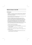
Opening the Unit
Open the display as follows.
1. The screen locking latch is located in the center of the front edge of the
notebook. Slide the latch to the right and then raise the screen cover.
2. Set the display to the best viewing angle.
Screen
Latch
1-3
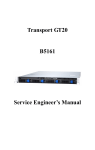
Inside the Main Unit
Power Indicators
Activity Indicators
Color Display
Stereo Speakers
Keyboard
Power
Switch
GlidePoint
Microphone
Color Display
The PC-9300T uses an active matrix color display which has a diagonal length of
11.3".
The PC-9300D uses a dual scan color display which has a diagonal length of
12.1".
Power Switch
This switch turns on the power to the system. To turn the power on, press this
switch. When the notebook has been suspended to disk, the power switch is used
to resume it.
1-4
Keyboard
The keyboard has 87 keys (US English) or 88 keys (others). Many functions of
the notebook can be controlled by pressing special key combinations (hot keys).
Stereo Speakers
The speakers will output the sound that your notebook's software generates, or the
sound that you input through the sound ports.
Caution: Avoid placing floppy disks, or other magnetic storage media on
top of the speakers. The magnet inside the speakers may damage the data
on the disk.
GlidePoint
The GlidePoint is located just in front of the keyboard. The left and right selection
buttons are placed just in front of the GlidePoint surface. The GlidePoint
functions just like a mouse or trackball.
Power Indicators
The three power indicator lamps are located between the hinges of the screen
cover. From left to right, the power indicators have the following functions.
AC Power
When the notebook is operating using power supplied
through the AC adapter, this indicator turns on with a green
color when the notebook is on, or blinks when the notebook
is in the suspend to RAM mode.
Battery Power
When the notebook is operating using power supplied
through the internal battery, this indicator turns on with a
green color when the notebook is on, or blinks when the
notebook is in the suspend to RAM mode.
Battery Charge
This indicator shows the status of the battery. When the
battery is charging it turns on with an amber color. When the
battery is fully charged, it changes to green. When the
battery is low on charge, it flashes with a red color.
1-5
Activity Indicators
The six activity indicators are located just above the center of the keyboard. The
lamps turn on when the function that they represent is active. From left to right,
the activity indicators have the following functions.
CD-ROM
This indicator turns on whenever the system is reading from
a disc in the CD-ROM drive.
Hard Disk Drive
This indicator turns on whenever the system is reading from,
or writing to the hard disk drive.
Floppy Disk Drive
This indicator turns on whenever the system is reading from,
or writing to a diskette in the floppy disk drive.
Num Lock
This indicator turns on when the keyboard is in Num Lock
mode. In this mode, the numeric keypad embedded in the
keyboard becomes active.
Caps Lock
This indicator turns on when the keyboard is in Caps Lock
mode. In this mode, all typed text uses capital letters.
Scroll Lock
This indicator turns on when the keyboard is in Scroll Lock
mode. In this mode, text will scroll onscreen without
changing the position of the cursor.
Microphone
The microphone is located near the front right edge of the notebook. The
microphone can be used to record sounds, or it can act as a telephone mouthpiece
when you are using the built-in fax/modem as a speakerphone (US and Canada
only) (PC-9300T only).
1-6
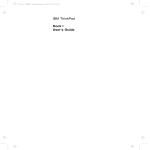
Right-side Components
CD-ROM Drive
Infrared Port
CD-ROM Drive
The CD-ROM drive can be used to read from CD-ROM data discs, video discs,
and audio discs. Your notebook identifies the CD-ROM drive as drive R.
Infrared Port
The infrared port supports the ASK infrared standard, and also the IrDA infrared
standard. Your notebook identifies the infrared port as COM2.
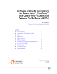
Left-side Components
Security
Cable Anchor
Audio Ports
PC Card Slots
Telephone
(RJ11) Socket
Floppy Disk
Eject Button
Floppy Disk
Drive
Security Cable Anchor
This rectangular hole can be used as an anchor point for a computer security
cable. You can use this cable to lock your notebook to a desk or some other
secure location, and so prevent theft.
PC Card Slots
1-7
There are two Type-II PC card slots. You can also use a Type-III PC card in the
lower slot. The lower slot has an integrated Zoomed Video port so that you can
use PC cards that support the Zoomed Video standard (ZV cards) in the lower
slot. Eject buttons for both slots are placed at the right side of the slots. The
buttons are folded down when not in use. Your notebook identifies the PC card
slots as drives D and E, when you are using PC cards that store data.
Audio Ports
The three audio ports are located below the PC card slots. From left to right the
audio ports are:
Audio Input Jack
You can use this jack to input stereo sound from other devices,
such as a radio or a tape recorder, into your notebook.
External
Microphone Jack
You can use this jack to input the sound from an external
microphone into your notebook. When an external microphone
is connected to this jack, the built-in microphone is
automatically disabled.
Audio Output
Jack
You can use this jack to output the sounds generated by your
notebook to an external device such as stereo loudspeakers or
headphones. When an external device is connected, the built-in
speakers are automatically disabled.
Telephone (RJ11) Socket (US and Canada only) (PC-9300T only)
The telephone socket is used to connect the internal fax/modem to a telephone
cable that terminates in an RJ11 connector.
Floppy Disk Drive
The floppy disk drive can be used to read and write to 3.5" floppy disks with
capacities of 720K or 1.44 MB. Your notebook identifies the floppy disk drive as
drive A.
Hard Disk Drive
The hard disk drive is an internal component. It operates using an Enhanced IDE
(Integrated Drive Electronics) interface. Your notebook identifies the hard disk
drive as drive C.
1-8
Rear-Edge Ports
Expansion
Connector
AC Adapter
Jack
External
Monitor
Port
RS-232C
Serial Port
Video Out Jack
Game /
MIDI
Port
Printer Port
PS/2 Port
The rear-edge of the notebook has two connector compartments and an AC
adapter jack. You can access the connector compartments by pulling the
compartment covers open.
Expansion Connector
The expansion connector is in a separate compartment. The expansion connector
is used to connect your notebook to an optional port replicator (CE-M50PR). For
information on the port replicator, see the manual supplied with the CE-M50PR
port replicator.
AC Adapter Jack
You can plug the cable from the AC adapter into the AC adapter jack in order to
power your notebook from the AC adapter.
External Monitor Port
You can use the external monitor port to connect your notebook to an external
monitor that supports Super VGA and extended SVGA resolutions.
RS-232C Serial Port
You can use this port to connect your notebook to a serial device such as a serial
printer or a serial mouse. Your notebook identifies this port as COM1.
Video Out Jack
Use the video out jack to connect your notebook to a PAL or NTSC format TV
receiver.
1-9
PS/2 Port
Use this port to connect your notebook to a PS/2 device such as an external
keyboard or an external pointing device.
Printer (Parallel) Port
Use this port to establish parallel communications with another device such as a
printer. Your notebook identifies the printer port as LPT1.
Game/MIDI Port
You can use this port to connect the notebook to a joystick or a MIDI device.
Components in the Unit Base
Battery Pack
Floppy Disk
Drive
Memory
Compartment
Battery Pack
The battery pack is removable. To remove the battery, slide the two latches open
and then remove the battery from the compartment.
Memory Compartment
The memory compartment can be used to install an optional memory module (CEA311B, CE-A312B, or CE-A323B) in order to add extra memory to your
notebook.
Floppy Disk Drive
The floppy disk drive can be easily removed for service. We recommend not to
remove the floppy disk drive module under normal operation.
1-10
CHAPTER 2
Using the Notebook for the
First Time
This chapter explains the procedures that you should follow the first time that you
use the notebook.
Connecting the AC Adapter
Your notebook can be powered by the internal, removable, rechargeable battery
pack, or it can be connected to a wall power outlet using the supplied AC adapter.
More information on the notebook's power requirements can be found in the topic
Power Supply in Chapter 4.
Note: Use the AC adapter to connect your computer to a power source
before turning on your notebook for the first time.
To start using your notebook, follow the steps below:
1. Make sure the notebook is turned off.
2. Connect the cable from the AC adapter to the AC adapter jack.
3. Connect the power cord to the AC adapter.
Caution: Only use the approved AC adapter (EA-905V) that is supplied
with the system. Do not use any other adapter than the one supplied with
the system. The AC adapter can be connected to a power outlet using a
voltage level of from AC 100 - 250 volts. The voltage rating of the power
cord is, however, variable from country to country. Please consult your
vendor for more information.
4.
Insert the AC power cord plug into a wall outlet.
To Wall
Outlet
AC Adapter
2-1
System Start-up and Shut-down
1.
2.
After you have connected the AC adapter, open up the screen cover by
sliding the screen locking latch to the right.
Press the power switch to turn on the notebook.
Note: If you see the following message at the boot time, press F2, then
Enter to run the Setup utility with the default values.
System battery is dead - Replace and run SETUP
Real time clock error
Mouse initialized
Press <F1> to resume, <F2> to Setup
In the Setup utility, set time, date and other fields appropriately. Then
press Esc, then Enter to save the values and restart the notebook. For
information on the Setup utility, see Chapter 3.
3.
Your notebook will execute a brief Power On Self Test. This test initializes
all the major components of the system and verifies that they are operating
correctly. The notebook will then load the Windows 95 operating system.
Note: If you press the F8 key while your notebook displays the message
“Starting Windows 95....”, you can select an alternate start-up than
Windows 95. See the Windows online help for more information.
4.
After the notebook has loaded Windows, you can click on the Start menu to
begin computing in the Windows environment.
Note: Access to Electronic Services like America Online and
CompuServe, as offered by this version of Windows 95, may not be
available in all countries of purchase of this notebook.
Personal Windows Installation
Windows 95 has been partially installed on your notebook. The first time you use
your notebook, Windows will automatically complete the installation by asking
for personal details such as your name, your time zone and so on. Follow the
onscreen prompts to complete the Windows installation.
2-2
Note: Some machines may show a Safe Recovery message when they are
turned on. This message is created because the notebook has been turned
on and then off again without the Windows 95 final installation. For
example, the system vendor may have turned the notebook on and off in
order to verify that it was operating correctly. You can ignore the Safe
Recovery message and continue with the Windows installation.
Setting the SHARP Original Wallpaper
After setting up Windows 95, set the SHARP original wallpaper in the following
procedure.
1.
2.
Double-click the “Click me to set up SHARP Wallpaper” icon on the
Windows desktop.
When the message appears, click OK. The SHARP original wallpaper is
displayed on the screen as a default.
System Shut Down
1.
2.
3.
Press the Alt + F4 keys, or click on Shut Down from the Start menu.
In the Shut Down Windows dialog box, select which method of shut down
you prefer, and then press the Enter key or click on the Yes button.
Your notebook will automatically shut down.
Note: Do not turn the power off or reboot while the system is accessing
any of the disk drives. This may result in damage to the drive or disk, or
loss of data. After the notebook is turned off, wait at least five seconds
before turning the notebook back on. Turning the power on and off too
quickly can damage the notebook.
When the notebook is turned off, we recommend that you keep the screen cover
closed to protect the screen from dust and/or damage.
2-3
Using The Keyboard
The built-in keyboard has 87 keys (US English) or 88 keys (Others).
About the Keyboard
The layout of your notebook's keyboard is similar to a normal keyboard. In
addition, there are twelve function keys, cursor control keys, and other special
function keys such as Ctrl, Alt, Esc, Prt Sc, Pause, Pg Up, Pg Dn, Home and
End.
Function Keys
Fn (Function) Key
Alphanumeric Keys
Numeric Keypad
Cursor Arrow Keys
The Numeric Keypad is embedded in the right-of-center alphanumeric keys. The
keypad is activated and deactivated by pressing the Num Lock key. The Num
Lock indicator turns on when in Num Lock mode.
2-4
Key Legends
The keycaps are engraved with different legends to indicate the function of the
key.
Large Light-Gray Legends
These represent the standard function of the key.
Small Blue Legends
These represent the function of the key if the Num Lock key has been pressed
and the keyboard is in Num Lock mode.
Function Key Icons
These represent special functions that are embedded into the Function Keys of the
keyboard. They are activated by holding down the Fn Function key and then
pressing the appropriate key.
Special Key Combinations
Special key combinations allow you to use various functions of the notebook
easily.
With the Ctrl and Alt Keys
Ctrl + Alt + Del
Pressing the Ctrl + Alt + Del key combination halts all operation of your
notebook and displays the message on the screen. Pressing this key combination
again will restart the notebook. This is known as a “warm boot”. This key
combination may be useful if you encounter hardware or software problems which
“lock up” your notebook.
Caution: The use of the Ctrl + Alt + Del key combination will result in
the loss of all data in memory.
With the Fn Key
The Fn key, in combination with other special keys, controls some of the
notebook's features. Symbols are printed on the keyboard to show the functions.
2-5
Fn + F3
This key combination decreases the volume of the audio
system. Hold down the keys until the volume is correct.
Fn + F4
This key combination increases the volume of the audio
system. Hold down the keys until the volume is correct.
Fn + F5
Each press of this key combination changes the video output
of the notebook. The operation of this key combination
changes depending on which display devices are connected
to your notebook on start-up. See the table below:
Ext. Monitor (LCD
TV Receiver
Ext. Monitor & TV Receiver
+ CRT)
(LCD + TV)
(LCD + CRT + TV)
Start-up Display
LCD + CRT
LCD
LCD + CRT
First Press
LCD
No Display
LCD
Second Press
CRT
*TV
CRT
Third Press
CRT Note 1
LCD
TV (& CRT) Note 1
Fourth Press
LCD + CRT
LCD
LCD + CRT
(Return to First)
* This display only occurs if you have Enabled the field Display to TV in the Advanced page of the
Setup utility.
Note 1: If the field Display to TV is Disabled, this key press is omitted. If the field Display to TV is
Enabled, the display on the external monitor will change to the resolution of a TV display.
Note: When using both the LCD and an external monitor at the same
time, the external monitor should have the capability to display 800 x 600
resolution. Some external monitors which support only 640 x 480
resolution do not work properly.
Fn + F6
This key combination darkens the built-in screen.
Fn + F7
This key combination brightens the built-in screen.
2-6
Fn + F8
This key combination decreases the contrast of the built-in
screen. Hold down the keys until the display is correct. This
function only operates if you have a DSTN (dual-scan)
color display.
Fn + F9
This key combination increases the contrast of the built-in
screen. Hold down the keys until the display is correct. This
function only operates if you have a DSTN (dual-scan)
color display.
This key combination switches the Battery Low beep on
and off. Note that this combination disables the beep
temporarily but does not change the data in the Setup utility.
Fn + F10
Fn + F11
This key combination turns off the backlight on the built-in
screen. Press the keys again to turn the backlight back on
again.
Fn + F12
This key combination puts your notebook into suspend
mode (either to disk or to RAM depending on the settings
of the Power page in the Setup utility).
Special Windows 95 Keys
This key can be used to open up the Start menu on the
Windows 95 Taskbar.
This key can be used as an alternative to the right mouse
button. For example, it opens a configuration menu for objects
on the Windows desktop.
2-7
CHAPTER 3
Setup Utility
Your notebook is installed with a Setup utility that lets you change the
configuration of the system, and customize the security and power management
parameters. This chapter explains how to run and use the Setup utility.
About the Setup Utility
Your notebook is set up correctly when it first ships. However, you might need to
change the system configuration settings such as date, time, password or power
management. The Setup utility consists of six menu pages:
Main
This page defines the basic system configuration.
Advanced
This page defines many of the input/output settings of the
system.
Security
This page defines the security functions of the system.
Power
This page defines the power management settings of the
system.
Boot
This page defines how the system boots (loads) an operating
system when it first turns on.
Exit
This page defines how you exit the Setup utility.
The settings that you define in the Setup utility are saved in CMOS RAM. The
information in CMOS RAM will not be erased even when you turn the notebook
off. Each time you turn it on, the notebook uses this information as a reference to
initialize the hardware, set up the power management routines, install the security
features, and so on.
Starting the Setup Utility
You can only access the Setup utility just after your notebook is turned on. If your
notebook is already turned on, shut it down and restart it. When your notebook
starts, a message appears telling you to Press <F2> to enter SETUP. Press the F2
key as soon as this message appears and the Setup utility will start.
3-1
Using the Setup Utility
The Setup utility menu bar has six choices: Main, Advanced, Security, Power,
Boot, and Exit. You can move between each of the six pages by using the left and
right arrow keys. Each page has a list of items, or fields. On the right of each field
there are one or more values. You can move a highlight up and down in the list of
values by using the cursor up and down arrow keys. If a field has more than one
value, you can move from one value to the next by pressing the Tab key.
When a value is highlighted, you can change it to an alternate value by pressing
the Minus key, or the Space Bar. The Space Bar progresses forwards through
the available values, while the Minus key runs backwards through the available
values.
Certain fields may require you to type in a value instead of selecting a preinstalled value. Some other fields are automatically set by the notebook, and so,
you cannot highlight the value and change it.
Some fields might be preceded by a !sign. When you highlight these fields and
press Enter, a sub-menu appears. You can make changes to the sub-menu values
in the same way as you change the main page values. When you finish making
changes to a sub-menu, press Esc to return to the original page.
You can make the fields in one page return to their default values by pressing the
F9 key. Pressing the F10 key restores the values you previously saved. If you
need help, you can display a help message by pressing the F1 key.
Leaving the Setup Utility
When you have made changes to the Setup utility, either press the Esc key, or use
the arrow keys to highlight the Exit menu on the menu bar. The Exit menu has
five options. Select the option you need.
Save Changes & Exit
When you select this option, any changes you made to the field values are saved,
and the notebook restarts using the new values.
Exit Without Saving Changes
3-2
When you select this option, any changes you have made to the field values are
discarded and the notebook restarts using the old values.
Get Default Values
When you select this option, the notebook loads the default field values. The
notebook does not restart. You must use the Save Changes & Exit option to restart
the notebook using the default values.
Load Previous Values
When you select this option, any changes you have made to the field values are
discarded. The notebook does not restart. You must use the Save Changes & Exit
option to restart the notebook using the old values.
Save Changes
When you select this option, any changes you have made to the field values are
saved. The notebook does not restart. You must use the Save Changes & Exit
option to restart the notebook using the new values.
3-3
Making Changes to the Main Page
The Main page of the Setup utility deals with the basic configuration of your
notebook, the hardware components, the system memory, and the date and time.
The illustration below shows the Main page screen.
PhoenixBIO S Setup - C opyright 1985 -95 Phoenix Technologies Ltd.
A dvanced
Security
Pow er
Boot
Exit
Item Specific H elp
System Tim e
System D ate
[15 :31:40 ]
[12/12/1996 ]
D iskette A
H ard D isk
Large D isk A ccess M ode
[Enabled ]
[A uto ] 1440 M b
[D O S ]
System M em ory:
Extended M em ory:
F1 H elp
ESC Exit
<Tab>,<Shift-Tab>,or
<Enter> Selects field.
640 KB
15 M B
-/SPA CE Change Values
Enter Select Sub-M enu
F9
Setup D efaults
F10 Previous V alues
Note: The size of the Extended Memory field value varies according to
the configuration of your notebook.
System Time
Use this field to install your notebook with the correct time. Your notebook uses a
24 hour clock and the time format is HRS:MINS:SECS. Use the Space Bar and
Minus keys to adjust each figure and press the Enter key after each figure is set.
System Date
Use this field to install your notebook with the correct date. The date format is
MONTH/DAY/YEAR. Use the Space Bar and Minus keys to adjust each figure
and press the Enter key after each figure is set.
3-4
Note: You can also change the time and date held by your notebook by
double-clicking on the time button at the left of the Windows Task Bar.
The Setup utility will automatically adjust the date and time to stay
current with the changes in Windows date and time.
Diskette A
Use this field to disable or enable the built-in floppy disk drive. You might want
to disable the floppy disk drive as a security measure.
Hard Disk
Leave this value at the default setting Auto.
Large Disk Access Mode
Normally you can leave this field at the default value DOS, since your notebook is
considered a DOS-type computer. If you install a completely different operating
system such as UNIX or Netware, you might need to change the value to Other.
System Memory and Extended Memory
These two fields are detected automatically at start-up time. Therefore you cannot
highlight these fields and make changes to the values.
3-5
Making Changes to the Advanced Page
The Advanced page is used to configure more advanced features in your
notebook. The illustration below shows the Advanced page.
PhoenixBIO S Setup - C opyright 1985 -95 Phoenix Technologies Ltd.
A dvanced
Security
Pow er
Boot
Exit
Item Specific H elp
CO M 1 port
CO M 2 port (For IR )
IR M ode
LPT port
LPT Extended M ode
EPP Version
[ D isabled ]
[2FB,IRQ 3 ]
[IrD A ]
[378,IRQ 7 ]
[Standard ]
[EPP 1.7 ]
Pointing D evice
K eyboard N um Lock
D isplay To TV
Resolution Expanded
[A uto ]
[Enabled ]
[D isabled ]
[D isabled ]
Set CO M port address
Sound C ard Setup
F1 H elp
ESC Exit
-/SPA CE Change V alues
Enter Select Sub-M enu
F9
Setup D efaults
F10 Previous V alues
COM 1 Port
This field lets you assign an address and an interrupt request number for the RS232C serial port on the rear side of your notebook. As a default, this value is set
to Disabled. To use the serial port, change the value appropriately so that it does
not conflict with other ports.
COM 2 Port (For IR)
This field lets you assign an address and an interrupt request number for the IR
port on the right side of your notebook. Leave this value at the default (2F8, IRQ
3) unless you have a specific reason to change the address and IRQ number. You
can also disable the port with this field.
3-6
IR Mode
Use this field to make the infrared port comply with the ASK or IrDA standard
for infrared communications.
LPT Port
This field lets you assign an address and an interrupt request number for the
parallel port on the rear side of your notebook. Leave this value at the default
(378, IRQ 7) unless you have a specific reason to change the address and IRQ
number. You can also disable the port with this field.
LPT Extended Mode
Use this field to make the parallel port comply with one of the different kinds of
parallel communications Standard, Bi-Directional, Enhanced Parallel Port (EPP
Mode), or Extended Capabilities Port (ECP Mode).
EPP Version
If you have configured the parallel port for EPP communications, use this field to
select EPP mode 1.7 or 1.9.
Pointing Device
If you use a PS/2 mouse connected to the PS/2 port, set the field to External PS/2
Mouse to disable the built-in GlidePoint. If you use a serial mouse connected to
the serial port, set this field to Disabled to disable the built-in GlidePoint.
Keyboard NumLock
If you use the PS/2 port to connect an external keyboard to your notebook, use
this field to disable the Num Lock key on the built-in keyboard and avoid
conflicts.
Display To TV
If you have used the video out jack to connect your notebook to a TV receiver or
other video device, use this field to configure the signal for either the PAL or
NTSC format. When this field is disabled, the video hot keys cannot be used to
switch the video output to the video out jack.
Resolution Expanded
If you are in DOS mode, or if you are running Windows at a low-resolution
display of 640 x 480, the display will not occupy the whole screen. Use this field
to expand the display so that it uses the whole of your 800 x 600 built-in screen.
3-7
Note: When you expand a 640 x 480 display to fill the whole screen, it
causes some distortion to the screen fonts, and other elements of the
display. This is unavoidable, and is not a malfunction of your notebook.
Sound Card Setup
When you highlight Sound Card and press Enter, the Setup utility will display
the sound card sub-menu fields. You can use the first field to turn the sound card
on or off. We recommend that you leave the other fields at their default values.
They should only need to be changed if they cause a conflict with another device
that you have connected to your notebook.
After you have made changes to the sound card sub-menu fields, press Esc to
return to the Advanced page of Setup.
Making Changes to the Security Page
The Security page lets you install different levels of security protection in your
notebook. You can install two levels of security, Supervisor and User, and you
can configure your notebook so that the holder of a user password cannot access
the floppy disk drive. The illustration below shows the Security page.
PhoenixBIO S Setup - C opyright 1985 -95 Phoenix Technologies Ltd.
A dvanced
Security
Pow er
Boot
Exit
Item Specific H elp
Supervisor Passw ord is
U ser Passw ord is
Set Supervisor Passw ord
Set U ser Passw ord
D isabled
D isabled
[Press Enter ]
Press Enter
Passw ord on boot
[D isabled ]
D iskette access
Boot Sector V irus Protection
F1 H elp
ESC Exit
3-8
[Supervisor ]
[Enabled ]
-/SPA CE Change Values
Enter Select Sub-M enu
F9
Setup D efaults
F10 Previous V alues
Supervisor Password is and User Password is
These two fields are for information only. They show if a supervisor password or
a user password has been installed.
Set Supervisor Password
Use this field to enter a supervisor password. Press Enter to display the Set
Supervisor Password window. See the following topic About Passwords for
information on installing and deleting passwords.
Caution: If you forget a password, you will be unable to use your
notebook. We recommend that you keep a written record of your
password in a secure location.
Set User Password
If you have set a supervisor password, you can then set a lower-level user
password. With a user password, you can enter the Setup utility and change or
remove the user password. You cannot change or remove the supervisor
password, nor enable diskette access if it has been disabled to the user. See the
following topic About Passwords for information on installing and deleting
passwords.
Password on Boot
As a default, you only need a password to access the Setup utility. If you enable
this field, you must type in the password every time the notebook is turned on. If
you do not type in the correct password, the notebook does not start. If both the
supervisor password and the user password is set and this field is set to Disabled,
the system assumes that the user is booting.
Diskette Access
This field is only available when the supervisor password has been used, or if no
passwords have been installed. If you set the value of this field to Supervisor, only
the supervisor can use the floppy disk drive.
Boot Sector Virus Protection
This field is only available when the supervisor password has been used, or if no
passwords have been installed. When this field is enabled, it provides some
protection against computer viruses which try to infect the boot sector of disks.
3-9
Caution: Disable this field before you format the hard disk drive, change
the partition structure of your hard disk, or re-install the system.
About Passwords
Using the password function, you can restrict which users can access the system
by entering the correct password. There are two passwords that can be set; a
supervisor password, and a user password. The holder of a supervisor password
has more access than the holder of a user password, and the supervisor can change
the access of the user.
System Start-up Access
If Password on Boot is set to enabled, the system cannot be started until the
correct password is entered.
Setup Utility Access
The Setup utility cannot be executed if the correct password is not entered. If a
user password is used to start the Setup utility, the following fields cannot be
accessed or changed.
•
•
•
Set Supervisor Password
Diskette Access
Boot Sector Virus Protection
Floppy Disk Drive Access
If the password protection is enabled, the floppy disk drive access is restricted. If,
in the Setup utility, Diskette Access is set to Supervisor, the floppy disk can only
be accessed if the supervisor password was used for system start-up. If set to
User, the floppy disk can be accessed whether the supervisor password or the user
password was used for system start-up.
Caution: If you forget your password, you will not be able to start or
setup the system. Be sure to use a password that you will not forget, or to
note it and keep it in a safe place. If three mistakes are made while
entering the password at system start-up or when running the Setup
utility, SYSTEM DISABLED will be displayed. In that case, turn the
notebook off, then on again.
3-10
Setting and Changing the Password
1.
2.
3.
4.
5.
Display the Setup utility Security menu.
Select the Set Supervisor Password field and press the Enter key.
Type in the supervisor password and press the Enter key. When changing the
password, type the new supervisor password.
For confirmation, type the new supervisor password one more time and press
the Enter key.
Press the Enter key. The setting of the item Supervisor Password is will
change to Enabled.
Note: To set the user password, select the Set User Password item, press
the Enter key, then follow steps 3 to 5 above to set the password or to
change it. The setting of the item User Password is will change to
Enabled. The user password can only be set if the supervisor password
has been set.
Passwords can be any combination of numbers and letters up to a maximum of 7
characters.
Deleting a Password
Follow the same procedure to set the password, but press the Enter key instead of
typing a password. The setting of the items Supervisor Password is and User
Password is will change to Disabled.
Note: When the supervisor password is deleted, the user password is
automatically deleted.
3-11
Making Changes to the Power Page
The Power page controls the power management routines that your notebook uses
to reduce power consumption. The illustration below shows the Power page.
PhoenixBIO S Setup - C opyright 1985 -95 Phoenix Technologies Ltd.
A dvanced
Security
Pow er
Boot
Exit
Item Specific H elp
Pow er M anagem ent
[Enabled ]
H ard D isk Pow er D ow n A fter [1 M in.]
[2 M in.]
Video Pow er D ow n A fter
[5 M in.]
A uto Suspend A fter
Suspend D ata To
A uto Save To D isk
Battery Low W arning Beep
SetPow er M anagem ent
enabled or disabled.
[RA M ]
[A fter 5 M in.]
[Enabled ]
F1 H elp
ESC Exit
-/SPA CE Change Values
Enter Select Sub-M enu
F9
Setup D efaults
F10 Previous V alues
Power Management
This field acts like a master switch for all the other powerdowns. If you disable
this field, none of the other system powerdowns will function. Use this field to
turn power management on and off.
Hard Disk Power Down After:
This field can be set to Disabled or it can specify a timeout from 1 to 15 minutes.
If the hard disk drive is not used for the time specified, it will automatically power
itself down. When the hard disk is next required, the drive will automatically be
re-supplied with power.
3-12
Video Power Down After:
This field can be set to Disabled or it can specify a timeout from 2 to 15 minutes.
If you do not operate the notebook and the screen is not changed for the time
specified, the built-in screen turns off. Any keystroke returns power to the screen.
Auto Suspend After:
This field can be set to Disabled or it can specify a timeout from 5 to 30 minutes.
If the notebook is not used for the time specified, it automatically suspends. The
notebook will suspend to disk or RAM, whichever value is selected in the next
field Suspend Data To. The timeout set in this field will not begin counting until
the timeout set in the field Video Power Down After has elapsed. If Video Power
Down After is disabled, Auto Suspend begins counting immediately.
Suspend Data To:
This field defines how the system suspends if the hot keys Fn + F12 are pressed,
or if the timeout value in the field above, Auto Suspend After, elapses. You can
program the notebook to suspend to disk or to RAM.
Auto Save To Disk
If the field Suspend Data To is set to Disk, this field is not required and it is
automatically disabled. If Suspend Data To is set to RAM, then you can use this
field to program the notebook to automatically suspend to disk, after it has
suspended to RAM. The timeout that you install in this field does not start
counting until the timeout installed in Auto Suspend After has elapsed.
Battery Low Warning Beep
You can use this field to turn on or off the battery low warning beep that the
notebook makes when battery power is low.
System Power Management
Your notebook is installed with two kinds of power management. One kind is
transparent, and operates automatically. The other kind is user-selectable, and you
can use the Power page to program how it operates.
3-13
Windows Power Management
Your notebook is designed to use the Windows power management routines to
transparently reduce system power consumption. Whenever the processor inside
your notebook is idle for a short time, the transparent power manager reduces the
clock speed of the processor so that it consumes less power. When the processor
resumes working, it returns to full speed almost instantaneously with no loss of
performance. This kind of power management is transparent and automatic, and
can save a great deal of energy.
Thermal Management
Your notebook monitors the processor's temperature. Before critical temperatures
can be generated, your notebook automatically slows down the processor until the
heat problem disappears. This procedure only occurs in exceptional conditions.
You may notice a slight loss of performance when your notebook takes this
course of action.
User-selectable Power Management
In addition to the transparent power management, you can program your notebook
to use progressively less and less energy and to eventually shut down altogether if
it is ever left idle. You can do this in the Power page of the system Setup utility.
About the Suspend Modes
Your notebook can either suspend to RAM or suspend to disk. The following
details how these two modes are different, and when to use one suspend rather
than the other.
Suspend to RAM
In a suspend to RAM, the contents of your notebook's memory are held intact,
while practically all the rest of the components in your notebook turn off
completely, or reduce power consumption to a minimum. In a suspend to RAM,
your notebook remains active but with the minimum possible power consumption.
You can return the notebook to full power by pressing the Space Bar.
If you are operating your notebook on battery power, a fully-charged battery can
maintain a suspend to RAM for many hours. The AC adapter can recharge the
battery while the notebook is suspended to RAM.
Suspend to Disk
3-14
Suspend to disk is really another way of turning your notebook off. When you
suspend to disk, the contents of your notebook's memory are copied to your hard
disk drive. When the contents of the memory have been safely stored to disk, your
notebook turns off. The next time the notebook is turned on after a suspend to
disk, the data on the hard disk is quickly read back into memory. In just a few
moments, your notebook appears exactly as it was when you last suspended to
disk.
Suspend to disk is very useful for Windows users who like to have many different
programs open and iconized on the Windows desktop. It can take quite a few
minutes to get a busy Windows desktop up and running, and then you have to shut
down each program one by one when you want to turn your notebook off. With
Suspend Data To set to Disk in Setup, you can simply press the suspend hot keys
and your custom Windows environment is saved to disk.
Suspend-to-disk Partition
In order to suspend to disk, you must have a special suspend-to-disk partition on
your hard disk drive. This partition must be created on your hard disk drive before
you begin installing your notebook's software.
Your notebook is pre-installed with a suspend-to-disk partition with a capacity of
51 MB. This is large enough to support a suspend to disk when the notebook is
installed with 48 MB of memory or less. If you happen to destroy this partition,
you will need to create a new suspend-to-disk partition. See the instructions in the
Re-installation Instructions.
Entering Suspend Mode
Your notebook will enter suspend mode under the following conditions:
•
•
•
•
•
If the time you set in Auto Suspend After has passed with no activity.
If the time you set in Auto Save to Disk has passed with no activity.
If the display panel is closed.
If the suspend hot keys Fn + F12 are pressed.
If Suspend is selected in the Windows Start menu.
Caution: Never close the display panel while your notebook is resuming
from the suspend mode.
3-15
Resuming from Suspend Mode
To resume from the suspend to RAM mode, press the Space Bar.
To resume from the suspend to disk mode, turn on the notebook. When you
resume from a suspend to disk mode, your notebook will restore to memory the
exact state that your notebook was in when it was suspended.
Caution: Do not touch the keyboard, GlidePoint, mouse, etc., while the
notebook is entering or resuming from the suspend mode, as that may
cause a malfunction. Do not let your notebook enter the suspend mode in
the following conditions:
• The system is playing or recording audio, photos, etc.
• The system is operating peripheral devices such as a printer.
Conditions that Prohibit Suspend Modes
Your notebook will not enter suspend mode under the following conditions:
•
•
•
•
•
•
The Power setting in Windows 95 is not set to manage power use on this
computer.
Windows 95 displays the clock.
An application that periodically writes to the screen is running on your
notebook.
The item Enable infrared communication on in the Infrared Monitor is
checked. You can see its status by selecting the Options tab of Control Panel Infrared Options.
The Disk Drives of Power Properties in Windows 95 are checked.
The item Disable in this hardware profile in the dialog box of Built-in
infrared port on laptop or desktop Properties is unchecked. You can see its
status by selecting Control Panel - System - Device Manager - Infrared Built-in infrared port on laptop or desktop Properties - General.
These are valid conditions for prohibiting the suspend mode. If you feel that your
notebook is not suspending correctly, please check that the conditions noted
above are not the cause.
Making Changes to the Boot Page
3-16
The Boot page of the Setup utility is a numbered list which defines the order in which
the notebook will try to load (boot) an operating system each time the system is turned
on. In the default condition, the Boot page appears like the illustration below.
PhoenixBIO S Setup - C opyright 1985 -95 Phoenix Technologies Ltd.
A dvanced
Security
Pow er
Boot
Exit
Item Specific H elp
1. D iskette D rive
2. H ard D rive
3. CD -RO M D rive
F1 H elp
ESC Exit
Select item to relocate
using the U P and D O W N
arrow keys.U se the '+'
and '_'keys to m ove
the highlighted book
device up ('+')or dow n
('_')in the priority
list.
-/SPA CE Change V alues
You can change the order of priority of the Boot page by highlighting one of the items
and then pressing the Space Bar. Each press advances the item one space up the list.
If you ever need to boot from a bootable CD-ROM disc, you can use this item to
advance the CD-ROM drive to the number one position in the list.
3-17
CHAPTER 4
Using the Notebook
This chapter shows you the basic operations of your notebook. The main subjects
covered are the power supply, the floppy disk drive, the hard disk drive, the CDROM drive, the fax/modem (US & Canada only) (PC-9300T only), the
GlidePoint, using PC cards in the PC card slots, and the IR port.
Power Supply
The notebook can be powered by one of the following methods.
•
•
From an AC wall outlet.
From the battery pack.
Note: Use the AC adapter whenever possible. Use the battery pack only
when an AC wall outlet is not available.
Using the AC Adapter
The AC adapter converts the AC power from a wall outlet into a DC current that
can be used by the notebook. The AC adapter can use wall outlets with voltages
ranging from 100V up to 250V. To power the notebook, connect the output cable
from the adapter to the AC adapter jack on the rear side of the notebook. Then use
the power cord supplied to connect the adapter to a wall outlet.
Note: For more information on how to connect the AC adapter and for
warnings regarding its use, please refer to the topic Connecting the AC
Adapter in Chapter 2.
Power
Indicator
Use Power
Cord to
connect to Wall
Outlet
Plug into AC
Adapter Jack
on Notebook
4-1
Using the Battery Pack
When a wall outlet is not available, you can use the rechargeable battery pack to
power your notebook. When you are using the battery pack to power your
notebook for a long time, we recommend that you enable the automatic suspend
to disk function of the system’s Power Management, according to the steps
below. See System Power Management in Chapter 3 for more details.
1. Turn on the notebook.
2. As soon as you see the message “Press <F2> to enter SETUP”, press F2 to
display the Setup utility.
3. In the Power page of the Setup utility, change the value of the field Power
Management to Enabled, and then change the value of the field Auto Save to
Disk to After 5 Min. (This assumes that the field Suspend Data To is set to
RAM.)
4. Press the Esc key; and then press the Enter key twice to restart your
notebook under the new power management settings.
When it is fully charged, a standard battery pack can power the notebook for
about 2 hours. The duration depends on the condition of the battery, and on usage
and the options that are installed in your notebook.
Recharging the Battery
Whenever your notebook is connected to a wall outlet through the AC adapter,
the battery will automatically begin charging if it is less than fully charged. The
battery charge indicator will turn on with an amber color to indicate that the
battery is being charged.
If your notebook is turned off, it will take about 4 hours to completely recharge an
empty battery pack. If your notebook is in the suspend to RAM mode, it will take
about 6 hours to completely recharge an empty battery pack. When the battery
pack is fully charged, the battery charge indicator will change from an amber
color to a green color.
Battery Low Indications
When the battery level is low and only a few minutes of power are left, the battery
charge indicator will begin to flash off and on with a red color, and the notebook
will begin to emit an audible beep.
4-2
The calibration of the battery low level assumes that the notebook is running
normally and no peripheral components are turned on. If, however, you are
running many components, such as the sound system, the PC card slots, the CDROM drive, and so on, you might have much less than a couple of minutes power
remaining when the battery low indications turn on.
Therefore when the battery low indications begin, you should immediately save
your work and either:
•
•
close all the applications that are open and then shut down the notebook
suspend the notebook to disk
After the notebook has been turned off or suspended to disk due to a low battery,
you cannot restart the notebook until you have either connected the AC adapter to
a wall outlet, or replaced the low battery with a fresh, charged battery.
Note: If the notebook is in suspend to RAM mode when the battery low
level is reached, the notebook will automatically turn off instead of
suspending.
Initializing the Battery
The battery installed in your notebook has the ability to accurately monitor the
amount of charge held by the battery and relay the information to the “battery
meter” in your notebook. If you ever replace the internal battery with a new one,
or if you feel that the Windows battery meter is not measuring the battery charge
accurately, you must initialize the battery so that the “battery meter” in Windows
95 is calibrated correctly.
1. Turn on the notebook and enter the Setup utility by pressing the F2 key at the
prompt.
2. Disconnect the AC adapter and leave the notebook turned on until the battery
is empty and the notebook shuts down.
3. Connect the AC adapter until the battery is fully charged. While the battery is
being charged, the battery charge indicator turns on with an amber color, and
when fully charged, the battery charge indicator changes to a green color.
4. Repeat steps 2 and 3 to fully discharge and recharge the battery once more.
The battery is now initialized. The Windows battery meter is accurately
calibrated with the charge potential of your battery.
4-3
Caution: Do not connect the AC adapter to your notebook during the
discharging of the battery. This will cancel the initialization of the
battery.
Battery Condition
Your battery pack will store more charge if you keep it in good condition. To
maintain good battery condition, it helps if you can frequently discharge the
battery until it is completely empty, and then recharge the battery until it is
completely full. This procedure ensures that the battery stores a maximum charge.
The condition of the battery pack will deteriorate over time. After 2 or 3 hundred
cycles of charging and discharging the battery, you may notice that it begins to
store less charge. When this happens, you might consider replacing the original
battery pack with a new battery pack (CE-M50EB).
Storing and Retrieving Data
One of the most important functions of any kind of computer is to store data, and
retrieve data that has been stored or recorded. Your notebook is very versatile and
it can store and retrieve data from many different kinds of media.
Floppy Disk Drive
The floppy disk drive can read and write to 3.5" disks which can store either
720K (2DD disks) or 1.44MB (2HD disks) of data. The floppy disk drive in your
notebook is normally identified as drive A.
Hard Disk Drive
Your notebook is installed with a hard disk drive, which can store more than 1
GB of data. Access to the hard disk drive is very fast. Your notebook identifies
the hard disk drive as drive C. The hard disk drive in your notebook is preinstalled with many software titles so that your notebook is ready for action as
soon as you take it out of the box.
To prevent damaging the hard disk and to protect the data on the disk, see the
points below:
•
4-4
Do not turn the power off or reboot the notebook while the hard disk indicator
lamp is turned on.
•
Do not drop the notebook or submit it to strong shocks.
CD-ROM Drive
Your notebook is installed with a CD-ROM drive. CD-ROM discs can be used to
store data, video or audio files, and software applications. The discs are not
erasable but they store a tremendous amount of data so they are ideal for
distributing long files.
Compact Disc Maintenance
If the recorded side is dirty, wipe the disc, from the center out to the edge, with a
dry soft cloth. If it is wiped in the opposite direction (from the edge towards the
center) or in a circular direction, you may damage the disc. Never use the
following products on a disc:
•
•
•
•
Alcohol, benzene, thinner or other cleaning solvents
Cleaning fluids containing abrasives
Sprays or cleaners for vinyl discs
Anti-static products
Using the CD-ROM Drive
Your notebook is installed with a special software application named Sharp
Player. Sharp Player lets you operate the CD-ROM interactively by pointing and
clicking on the user-friendly interface. You can consult the online help that is
provided with Sharp Player for information on using the program.
Caution: If you are using the CD-ROM drive, we recommend that you
disable the power management routines in your notebook. The power
management can interfere with the transmission of data so that audio or
video files don't run smoothly.
4-5
Inserting a CD
1.
2.
3.
Turn on your notebook.
Press the eject button and the disc tray will open slightly.
Carefully pull the tray fully open.
4.
5.
Place the disc in the tray with the printed side facing up.
Push down the disc lightly. A click sound can be heard when the disc is
correctly installed.
Carefully push the disc tray back into the notebook until it clicks and locks
closed.
6.
Caution: Do not leave the disc tray opened if it's not in use. Never touch
the lens with your fingers as it can be damaged by dust or fingerprints.
Only clean a dirty lens with a clean, lint-free swab that does not leave a
residue on the lens.
Ejecting a CD
1.
2.
3.
4.
5.
4-6
Turn on your notebook.
Press the eject button and the tray will open slightly.
Carefully pull the disc tray fully open.
Remove the disc from the tray.
Carefully push the disc tray back into the notebook until it clicks and locks
closed.
Caution: When the tray is opened, the disc might still be spinning. In
this case, please wait until the disc stops before removing it. Do not
eject a disc when the CD-ROM icon shows that the disc is still being
accessed by the notebook.
Maximum output and wavelength of the laser: 4.3mW, 780nm
CLASS 1LASER PRODUCT
LASER KLASSE 1
Using the Fax/modem (US & Canada only)
(PC-9300T only)
The fax/modem is an internal component that is built into your notebook. The
fax/modem can transmit and receive data at up to 33.6 Kbps, and can send and
receive faxes at up to 14.4 Kbps. Your notebook is installed with a
communications utility called SuperVoice. The SuperVoice software integrates
the fax/modem with your notebook’s audio system so that you can install TAM
(telephone answering machine) functions into your notebook.
For example, you can turn your notebook into a speakerphone, so that the
notebook speakers output the incoming call, and the microphone acts as a
telephone mouthpiece. You can install your notebook with voice mail so that
incoming messages are stored as audio files while you are absent.
Connecting the Fax/modem
On the left side of your notebook there is an RJ11 (telephone) socket. This socket
is connected to the internal fax/modem. In order to use your fax/modem, you must
connect a working telephone cable into the RJ11 socket. A telephone cable, with
RJ11 plugs at either end is supplied with your notebook.
4-7
RJ11 Socket
After you have connected the telephone cable, click on the Windows Start button,
and then click on the SuperVoice icon in the Programs list. Follow the
instructions in the SuperVoice online help, to install the features that you want to
operate on your fax/modem.
GlidePoint
The pointing device built into your notebook is called a GlidePoint. The
GlidePoint is a PS/2 device that functions just like a mouse and is compatible with
a PS/2 mouse. You can use the GlidePoint to start, stop, and control operations in
the Windows environment by pointing and clicking, and dragging and dropping.
Caution: Do not hit or scratch the GlidePoint pad surface with a sharp
object, such as the point of a pen or pencil. Do not use the GlidePoint if
your fingers are wet or damp. These actions may cause improper
operation.
Note: To clean the GlidePoint, first turn off the notebook; then wipe the
surface with a dry soft cloth.
4-8
Using the GlidePoint
The GlidePoint consists of a GlidePoint surface and two buttons. The surface acts
as a representation of the notebook display.
Moving the Cursor
When you slide a fingertip across the GlidePoint surface, the cursor on the display
moves in the same direction across the display.
Clicking the Buttons
The two buttons in front of the GlidePoint are used like the left and right buttons
on a standard mouse. Press or double-press a button to execute a left or right
mouse click or double-click. You can also simulate a button click by lightly
tapping once on the GlidePoint surface, or twice for a double-click.
Using an Alternative Device
Optionally, you can connect an external pointing device to your notebook through
the PS/2 port or the serial port. You can use the Advanced page in the Setup
utility to disable the built-in GlidePoint if you prefer. It is not necessary, however,
to disable the GlidePoint even when you have connected a PS/2 mouse.
4-9
PC Card Slots
The left hand side of your notebook is equipped with a PC card compartment. The
compartment contains two Type-II slots stacked one on top of the other, or one
Type-III slot (using the lower slot only). You can install these slots with PC cards
that can add different kinds of features or functions to your notebook.
LAN Adapter Card
This kind of card lets your notebook connect to a Local Area Network.
SCSI Interface Card
This kind of card gives your notebook a SCSI interface so that you can add SCSI
devices to your system.
ATA Device
Used for rotating or solid state large storage capacity devices equipped with an
AT attachment such as an IDE hard disk. The ATA device does not require an
external power supply to keep the data stored even after it is removed from the
slot.
SRAM Memory Card
A Static RAM memory card can be formatted like a floppy disk, and it comes
with a write-protection switch on its edge. The card has an internal battery to
maintain the data stored on the card after it is removed from the slot.
ZV Cards
ZV (Zoomed Video) cards are cards that adhere to the Zoomed Video
specification which allows for fast video access to the system. The lower slot
supports ZV cards, so a ZV card must always be inserted into the lower slot.
Note: A ZV card or some cards need ZV-port compliant PC card drivers,
while other cards may not work if this driver is installed. For further
instructions, see the Re-installation Instructions.
FLASH Memory Card
A solid state storage device similar to a floppy disk, which has a switch on its
edge to protect the stored data. Unlike SRAM cards, a FLASH memory card does
not need an internal battery to maintain the data stored on the card.
Note: Your notebook can use only the FLASH memory cards usable as
ATA devices.
4-10
Inserting and Removing PC Cards
PC cards can be inserted and removed just like a floppy disk.
Type-II cards:
Can be used in the upper or lower slot. You can insert two Type-II cards in your
notebook at the same time.
Type-III cards:
Can only be used in the lower slot. When a Type-III card is installed, the upper
slot cannot be used.
ZV Cards:
Can only be used in the lower slot which has an integrated Zoomed Video port.
Note: Memory cards or ATA cards must be formatted before they can be
used to store data.
Inserting PC Cards
1.
2.
The label on the PC card is normally placed on the upper side of the card.
Align the PC card with the slot, and carefully insert the card all the way into
the slot until you feel it engage with the connector inside the slot.
If your notebook emits a double beep, this means that your notebook has
successfully recognized and configured the card. If your notebook emits a
single beep, this means that it has been unable to recognize and configure the
card.
Note: Some PC cards need to use resources such as Interrupt Requests
(IRQs) and I/O Addresses. These resources are limited and many of these
resources are required by other components in your notebook. You can
examine the resources used by your notebook by opening the Control
Panel and clicking on the System icon. Click on the Device Manager tab
to show a list of the devices installed in your notebook. Click on the
Properties button to show the resources used by a highlighted device.
4-11
Ejecting PC Cards
1.
2.
3.
4.
5.
From the Start menu, select Settings - Control Panel.
Click the PC card icon.
Select the card you want to remove, and click Stop.
When the message This device can be safely removed is displayed, click on
the OK button.
Pull out the card slot eject button, then push it in to eject the PC card. Slide
the card all the way out of the PC card slot.
Caution: Some PC cards may become a little hot if they have been in use
for a long time. Be careful when removing such cards.
Installing PC Card Drivers
Normally, when a PC card is inserted into the PC card slot, Windows 95 will
recognize the card, and install the appropriate driver so that your notebook can
use the card.
If Windows 95 cannot recognize a card and install the appropriate driver, it will
display a dialog box so that you can manually instruct Windows what kind of PC
card driver is required. Follow the instructions that are displayed by Windows.
Windows may completely fail to recognize some ATA devices (for example, a
hard disk drive). You might have to take the following actions to fix the problem.
1.
2.
3.
4.
5.
6.
7.
8.
9.
4-12
Eject the PC card.
Click on the Start button and then select Control Panel from the Settings
menu.
Double click on the System icon, and then click on the Device Manager tab.
Double click on Hard Disk Controller.
Remove the registered controller.
Insert the PC card ejected at step (1).
Double click on Hard Disk Controller.
Double click on the newly installed controller to install it.
Select Resources. Remove the check mark from the Use automatic settings,
and change Settings based on to Basic configuration 0002 or over, in which
you can edit Input/Output Range.
10. Select Input/Output Range in the Resource settings and click on the
Changing Setting button.
11. Select the value between 0100 and 03A0 by pressing the σ or τ button so that
the conflicts information indicates No conflicts.
12. Click on the OK button twice and then click on the YES button.
Setting the COM Port
Some PC cards use the COM3 or COM4 port address. The COM1 and COM2
ports of your notebook are already used by other devices, and COM3 or COM4
may conflict with those ports.
When a PC card uses the COM3 port address, go to the Advanced page of the
Setup utility and disable the field COM 1 Port.
When a PC card uses the COM4 port address, go to the Advanced page of the
Setup utility and disable the field COM 2 Port (For IR).
4-13
Infrared Communications
The IR port on the right side of the notebook lets you communicate with wireless
LAN ports, and other devices equipped with an IR port such as printers,
notebooks, and electronic organizers.
Positioning and Preparing the Notebook and the Target
Device
Before you establish wireless communication, both the notebook and the target
device should be properly positioned. Locate your notebook on a flat surface and
then place the target device so that the IR ports of the notebook and target are in
line and within approximately 30 inches (80 cm) of each other. You should also
refer to the target device's manual to prepare it for IR communication.
Note: When communicating with a Sharp electronic organizer, make sure
the IR ports are no more than 15 inches (40 cm) apart.
Sharp Import/Export
Sharp Import/Export facilitates ASK-compatible IR data communications. Refer
to the Sharp Import/Export User's Guide provided with the notebook for details.
TranXit
The TranXit utility facilitates IrDA-compatible IR data communications. Refer to
the TranXit Quick Reference Guide provided with the notebook for details.
Note: Make sure that the Infrared Monitor is disabled before using
TranXit. To disable the Infrared Monitor, double-click the Infrared icon
in the Control Panel, and then click the Options tab. Clear the check box
for the item Enable infrared communication on and press the OK button.
4-14
Infrared Monitor
The Infrared Monitor controls the IR port in compliance with the Infrared Data
Association (IrDA). Although the physical IR port on your notebook is assigned
to COM2, the Infrared Monitor assigns the logical IR port to COM4 as a default
for Windows 95 communication applications such as Direct Cable Connection. It
also assigns the logical printer port to LPT3 as a default for printers which
support IR communications. When you run Windows 95 applications using the IR
port, select the logical IR ports COM4 and LPT3 as defaults.
4-15
CHAPTER 5
System Expansion
In this chapter you will find instructions on how to expand your notebook by
connecting it to peripheral devices such as a printer, an external monitor, and so
on.
Installation Safety Precautions
The parts and components of this notebook can be damaged by static electricity.
When handling or connecting components, please follow the precautions below.
•
•
Before connecting any device for system expansion, make sure the notebook is
turned off.
Memory modules have exposed circuit boards. Never touch the surface of the
circuit boards. When the devices are removed from their anti-static packaging,
place them carefully on a static-free surface.
5-1
Installing a Memory Module
Your notebook comes with 16 MB of memory pre-installed. If you want to
expand the memory size, you can install any of the following modules; 8 MB
(CE-A311B), 16 MB (CE-A312B), or 32 MB (CE-A323B).
A memory module can be installed in the memory compartment in the base of the
notebook. You can install the memory module quite easily.
Follow the steps below to install a memory module. Please refer also to the
Installation Safety Precautions at the beginning of this chapter.
1.
2.
3.
4.
Turn off the notebook and disconnect the AC adapter.
Turn the notebook over and place it on a flat surface.
Locate the memory compartment. Remove the cover of the compartment by
carefully levering the cover upwards.
There are two vertical connectors inside the memory compartment and two
connectors on the base of the memory module. You will notice that one
corner of the module connectors is beveled. When you turn the module over
to install it, the beveled corner of the connector is nearest to the back side of
the notebook.
Memory
Module
Connectors
5.
6.
5-2
Align the memory module properly according to step 4 and carefully install
the memory module into the compartment. Press the module down quite
firmly to ensure that it is seated correctly in the compartment.
Replace the compartment cover and restart your notebook. The notebook
automatically registers and uses the new memory.
Beveled Corners
Memory
Module
Changing the Battery
If you frequently operate your notebook using battery power, we recommend that
you purchase a spare battery pack (CE-M50EB). If you carry two charged battery
packs, you can count on more than four hours autonomous operation from your
notebook.
Caution: Always make sure that the battery pack is correctly installed.
Damaged or incorrectly installed batteries can be hazardous. Never
attempt to use any other battery pack than the approved battery (CEM50EB).
1.
2.
3.
4.
Turn off the notebook.
Close the screen cover and turn the notebook over.
Locate the center latch and the edge latch that secure the battery pack in the
base of the notebook.
Slide the center latch back outwards, and then slide the edge latch away from
the side of the notebook.
Edge Latch
Center Latch
5-3
5.
6.
7.
Use the gap created by sliding the edge latch open to raise the outer edge of
the battery pack out of the battery compartment.
You can then remove the battery completely.
Install the replacement battery back and ensure that the center and edge
latches are engaged, and the battery is secure.
Using the Parallel Port
Follow the steps below to connect a printer, or other parallel device, to your
notebook.
1. Turn off the notebook and pull down the cover on the back side of the
notebook.
2. Connect the printer cable to the parallel port in the connector compartment.
3. Restart your notebook.
Parallel Port
1.
5-4
If you want to change the parameters of the parallel port, for example, if you
are using a device which supports an Enhanced Parallel Port (EPP) or an
Extended Capabilities Port (ECP), restart your notebook and press F2 to run
the Setup utility. In the Advanced page of the utility, you can change the way
the parallel port operates.
Using the External Monitor Port
Follow the steps below to connect an external Super VGA monitor to your
notebook.
1. Turn off the notebook and pull down the connector compartment cover on the
back edge of the notebook.
3. Connect the video signal cable to the external monitor port in the connector
compartment.
External Monitor Port
3.
Plug the monitor power cable into a wall outlet. Turn on the monitor and then
turn on the notebook.
Switching the Video Display
You can switch the video output of the notebook from the built-in screen to the
external monitor port, the video out jack, or even a simultaneous display on the
screen and a monitor connected to the external monitor port. You can switch the
display with software (using the Display Device utility) or with hardware, using
the display hot keys. We recommend that you use software when you are
switching the display to new devices. If you regularly use the same device, you
can use the display hot keys after you have established that the video switches to
the device without problems.
Switching the Video with Software
1.
2.
3.
From the Start menu, Click on Settings-Control Panel.
Double click on the Display icon.
Click the Display Device tab
5-5
•
•
•
In the TV Standard area, you can define the TV receiver to be either PAL or
NTSC format.
In the Display Device area, you can direct the video to a CRT, to a TV, to an
LCD (liquid crystal display, i.e. the built-in screen), or a simultaneous display
to the CRT and LCD. You can also define the number of colors in the video
display, according to the capabilities of the display device.
In the External Display Detection area, your notebook can display information
on any external video devices that it detects.
Switching the Video with Hot Keys
You can switch the video display by pressing the video hot keys Fn + F5. Each
press of these keys cycles the video through four options.
Ext. Monitor (LCD
TV Receiver
Ext. Monitor & TV Receiver
+ CRT)
(LCD + TV)
(LCD + CRT + TV)
Start-up Display
LCD + CRT
LCD
LCD + CRT
First Press
LCD
No Display
LCD
Second Press
CRT
*TV
CRT
Third Press
CRT Note 1
LCD
TV (& CRT) Note 1
Fourth Press
LCD + CRT
LCD
LCD + CRT
(Return to First)
* This display only occurs if you have Enabled the field Display to TV in the Advanced page of the
Setup utility.
Note 1: If the field Display to TV is Disabled, this key press is omitted. If the field Display to TV is
Enabled, the display on the external monitor will change to the resolution of a TV display.
Note: When using both the LCD and the external monitor at the same
time, the external monitor should have 800x600 resolution capability.
Some external monitors which support only 640x480 resolution do not
work properly. We recommend that you use software to switch the
display.
5-6
Resolution and Number of Colors Displayed
You can change the resolution and the number of colors displayed as follows:
1. From the Start menu, click on Settings-Control Panel.
2. Double-click on the Display icon.
3. Click the Settings tab.
4. Select the number of colors from Color palette, and the resolution from
Desktop area.
Note: The number of colors in each setting is as follows:
High Color (16 bits)
65,536 colors
True Color (24 bits)
16,770,000 colors
If you set to True Color (24 bits) in Color palette:
• The drawing speed may be a little slow
• There may be some distortion on the screen when displaying video or
animation
• You cannot display video when using a ZV card compliant PC card.
The following table shows the resolution and the number of colors displayed on
each display device:
Resolution
640 x 480
1024 x 768
LCD
256
65,536
16,770,000 (*1)
256
65,536
16,770,000 (*1)
-
1280 x 1024
1600 x 1200
-
800 x 600
CRT
256
65,536
16,770,000
256
65,536
16,770,000
256
65,536
256
256
TV
256
-
LCD & CRT (*2)
256
65,536
16,770,000 (*3)
256
65,536
16,770,000 (*3)
-
-
-
-
(*1) The number of colors is set to 16,770,000, but the actual number of colors
displayed is 260,000 in PC-9300T and 220,000 in PC-9300D.
(*2) For simultaneous display, use a monitor with more than 800 x 600 resolution
capability. A monitor of only 640 x 480 resolution cannot display simultaneously.
(*3) Actual number of colors displayed is 260,000 (PC-9300T) or 220,000 (PC-9300D)
on the built-in display, and 16,770,000 on an external monitor.
5-7
Using the RS-232C Serial Port
Follow the steps below to connect a serial device to your notebook.
1. Turn off the notebook and pull down the connector compartment cover on the
back side of the notebook.
2. Connect the serial data cable to the RS-232C serial port in the connector
compartment.
Serial Port
3.
4.
5.
Restart your notebook and, if required, supply power to the serial device.
You might have to install and configure software in order to use a device that
is connected to the RS-232C serial port. You might need the information that
your notebook identifies the serial port as COM1.
As a default, the COM1 port of your notebook is disabled. In order to use this
port, enter the Advanced page of the Setup utility and set the COM 1 Port
field appropriately.
Using the PS/2 Port
Follow the steps below to connect a PS/2 device, such as a keyboard or a mouse,
to your notebook.
1. Turn off the notebook and pull down the connector compartment cover on the
back side of the notebook.
2. Connect the PS/2 plug into the PS/2 port.
5-8
PS/2 Port
3.
4.
5.
Restart your notebook.
If you have connected a pointing device such as a mouse or a trackball, you
can (optionally) press F2 to run the Setup utility and use the item Pointing
Device in the Advanced page to disable the built-in GlidePoint. Your
notebook will continue to function normally even if you have connected an
external pointing device and the Glidepoint is not disabled.
If you have connected an external keyboard, the built-in keyboard will still
continue to be active. Optionally, you can press F2 to run the Setup utility
and use the Keyboard Num Lock item in the Advanced page to disable the
function of the Num Lock key on the built-in keyboard. This will prevent
conflicts with the use of the Num Lock key on the external keyboard.
Using the Video Out Jack
Use the video out jack to send the video generated by your notebook to an
external video device such as a TV receiver or a video cassette recorder.
1. Turn off the notebook and peripheral devices.
2. Using a standard audio/TV cable, connect your notebook to a TV receiver or
a video device. For information on making the connection, refer to the
instructions supplied with the audio/TV cable.
Video Out Jack
5-9
3.
4.
5.
6.
7.
8.
Turn on the TV receiver or video device, and then turn on the notebook.
When the setup prompt appears, press F2 to run the Setup utility.
In the Advanced page of the Setup utility, set the field Display to TV to NTSC
or PAL.
Set the TV receiver to video display mode.
From the Windows Start menu, select Settings, and then click on Control
Panel. Double-click on the Display icon and then click on the Display Device
tab.
In the Display Device window, check the item marked TV, and check the
item marked NTSC. The system will immediately send the video output to
the TV receiver using a resolution of 640 x 480. If the results are satisfactory,
click on the OK button to close the Display Device window.
When you want to return the display to the built-in screen (or an external
monitor), follow the steps above to open the Display Device window and
remove the check from the TV item. Check either the LCD or the CRT item
according to where you want to display the video.
Note: Some interference may occur when small characters are being
displayed on the TV.
5-10
Using the Audio Ports
You can output the sound generated by your notebook to external audio devices
and you can use external devices to input sound into your notebook.
External Microphone
Audio Input
Audio Output
Audio Input Jack
Use this jack to plug in an external audio source such as a radio or a tape
recorder.
External Microphone Jack
Use this jack to plug an external microphone into your notebook. When you use
this jack, the built-in microphone is disabled.
Audio Output Jack
Use this jack to output the notebook sound to an external audio device such as
headphones or speakers. When you use this jack, the built-in speakers are
disabled.
Using the Game/MIDI Port
You can connect a joystick or a MIDI device to the Game/MIDI port.
Game/MIDI Port
5-11
Setting a Joystick
1.
2.
3.
From the Windows Start menu, click on Settings-Control Panel.
Double-click the Joystick icon.
Set the properties appropriately.
Setting a MIDI Device
In order to use a MIDI device connected to the Game/MIDI port, follow the
instructions below.
1.
2.
3.
4.
5.
5-12
From the Windows Start menu, click on Settings-Control Panel.
Double click the Multimedia icon.
Click the MIDI tab.
Select Single Instrument and External MIDI Port, then click OK.
Close the Control Panel.
APPENDIXES
Appendixes
The appendixes include useful information on maintaining your notebook, using the
software, the connector pin assignments, and so on.
Appendix A: System Maintenance
This appendix tells you how to look after your notebook to ensure problem-free
operation and maximum life.
Taking the Notebook on the Road
Your notebook has been designed to be highly portable. To prevent the risk of
problems when taking the notebook on the road, please follow the advice below.
•
•
•
•
•
•
•
•
Before going out, back-up the data from the hard disk onto floppy disks.
For complete security, carry a copy of the backed-up data with you, and also
copies of the original software.
Do not leave a compact disc in the CD-ROM drive when you are transporting
the notebook.
Do not leave a floppy disk in the floppy disk drive when you are transporting
the notebook.
Do not leave the notebook turned on when you are transporting the notebook.
This may damage the hard disk drive, or the data on the hard disk.
Disconnect the AC adapter from the notebook when you are transporting it.
If possible, carry a fully-charged spare battery pack. Always carry the AC
adapter.
When you are transporting the notebook, avoid subjecting it to excessive
shocks.
A-1
Cleaning the Notebook
Cleaning the Case
The plastic case of the notebook can be cleaned with a soft, dry cloth.
Note: Do not use cleaning products that contain solvents such as alcohol,
benzene or thinner as they may damage the notebook case. Turn off the
notebook before cleaning it.
Cleaning the Display
To clean the display, wipe it with a soft cloth that has been dipped in a mild
detergent solution and then thoroughly squeezed dry.
Cleaning the IR Port (Infrared Port)
If the IR port is dirty, wipe it clean with a soft, dry cloth. A dirty IR port may
cause communication problems.
Cleaning the GlidePoint
The GlidePoint surface can be cleaned with a soft, dry cloth.
A-2
Appendix B: Notes on Software
This appendix contains important notes on some of the software applications and
utility programs that have been pre-installed on your notebook.
About the Suspend-to-disk Partition
The suspend-to-disk partition is an area on the hard disk drive that is reserved for
the suspend-to-disk function. The suspend-to-disk function is a special way of
turning off the notebook.
When the notebook is suspended to disk, the contents of the system memory are
copied to the suspend-to-disk partition, and then the notebook turns off. When the
notebook is turned back on, the data in the suspend-to-disk partition is copied
back into system memory. In just a few seconds after power on, the notebook
appears exactly as it was when it was suspended to disk.
The suspend-to-disk partition must have a capacity that is 3 MB larger than the
total memory installed in the notebook (the extra 3 MB are required by the
notebook's video memory). In the standard configuration, the notebook is
installed with a 51 MB suspend-to-disk partition. This partition supports the
suspend-to-disk function for all memory configurations of your notebook (up to
48 MB).
B-1
Changing the Suspend-to-disk Partition Size
The suspend-to-disk partition size should be 3 MB bigger than the installed
memory. The table below shows the minimum size of the suspend-to-disk
partition that is required for different memory installations. The suspend-to-disk
partition is expressed in kilobytes (1 megabyte equals 1024 kilobytes) since this is
the figure you need when you use the PHDISK utility to create the new partition.
•
Installed Memory
Suspend-to-disk Partition
16 MB
19456 KB
24 MB
27648 KB
32 MB
35840 KB
48 MB
* 52224 KB
Size of the factory default suspend-to-disk partition
To create a new suspend-to-disk partition, see the following steps in the Reinstallation Instructions.
• Backing up the data
• Changing values in the Setup Utility
• Deleting the suspend-to-disk partition
• Deleting the DOS partition or Logical DOS Drives
• Creating the suspend-to-disk partition
Memory Management Software
If you install memory management software such as EMM386, QEMM, 386Max,
etc., you might find that it creates a conflict with the PC card drivers that your
notebook uses. This conflict can cause the notebook to hang up when you try to
close the Setup utility.
The solution to this problem is to modify the memory management software so
that it does not use the following system and BIOS memory locations:
D000-D7FF
Consult the documentation of your memory management software for the correct
method of excluding these memory locations.
B-2
If you are using the DOS memory manager EMM386, you can exclude these
memory locations by modifying the line in the CONFIG.SYS start-up file that
loads the memory manager so that it reads:
DEVICE=C:\DOS\EMM386.EXE options X=D000-D7FF
B-3
Appendix C: Troubleshooting
This appendix provides information on pinpointing and solving common
problems that you may encounter using the notebook.
Problems with your notebook can be caused by something as minor as an
unplugged power cord or as major as a damaged hard disk drive. The information
in this appendix is designed to help you find and solve minor problems. If you
still have a problem after trying all the suggested remedies in this appendix
contact your dealer.
The problems that you might encounter can be divided into two basic categories:
hardware and software. Hardware problems can be further divided into being of
an electrical or a mechanical nature. You will know you have a hardware problem
if, for example, the screen is blank, the notebook cannot recognize the disk drives,
or you get an error message during the Power-On Self Test (POST).
Software problems can occur at several levels. Both your operating system and
your software application programs are capable of generating errors and error
messages. If you encounter a software error, try to determine if the error message
is from your operating system or from an application program, and refer to the
appropriate manual for possible remedies.
You can also refer to the Windows 95 manual of Windows Help program to solve
the problem. To access the Help program, click the Start button, then point to
Help. It also gives you Troubleshooting tips and an Index.
Common Problems
Successful troubleshooting is the result of careful observation, deductive
reasoning, and an organized approach to solving the problem. If you encounter a
problem, begin by performing a careful visual inspection. Check the exterior of
the notebook first. If no lights are displayed, check the battery charge or power
outlet, the plug and power cord, and any power switches that may affect your
notebook. If the notebook has been connected to any peripheral devices, look for
loose or disconnected cables. You may also need to check the fuses and breakers
in your electric box.
C-1
A few common problems and suggested solutions are presented in the examples
which follow.
Question: Why doesn’t the power switch function?
•
If operating from a battery, it may be discharged. Connect the AC cord.
Question: Why can’t I start up the notebook?
•
Use a diagnostics software available commercially to check the notebook. If
you find the hard disk is damaged, you can format the hard disk by executing
the FORMAT command from the CD-ROM Setup Boot Disk, then re-install
Windows 95 from the CD-ROM Setup Boot Disk and Backup CD-ROM (you
will lose any data files you have not backed up).
Question: Why is the screen blank?
•
•
•
•
•
•
Press the Space Bar to see if any power management feature has blanked the
screen to save power.
Check the indicator lamps above the keyboard to verify that the notebook is
getting power. If the power indicator lamps are not lit, check the electrical
outlet, the AC adapter and the power cord.
If you are using a battery pack, make sure it has charge remaining, and that it
is installed correctly.
Check the brightness and contrast of your display.
Reset the notebook by pressing the Ctrl+Alt+Del keys.
Turn the notebook off, wait a few seconds, and then turn the notebook back
on.
Question: Why can’t I use a floppy disk?
•
•
•
•
C-2
The floppy disk may not be formatted, or could be corrupt.
If you can’t write to a floppy disk, the disk may be write-protected. Eject the
disk and ensure that the write-protect tab covers the detection hole.
If you can’t write to a floppy disk, the disk may be full. Use another disk.
The system BIOS boot settings for the floppy disk drive type may be
incorrect. In the Setup utility, ensure that Diskette A is set to Enabled.
Question: Why do I get a non-system disk or disk error message?
•
•
You may have inserted a non-bootable disk in drive A: (either a defective
disk or one without an installed operating system). Remove the disk.
If this message is issued when you attempt to boot from your hard disk drive,
insert a bootable disk and check the integrity of your hard disk drive.
Question: Why is the date and/or time incorrect?
•
•
Correct the data and time using the Windows Control Panel or the Setup
utility.
If the date and time are still incorrect when you reboot, contact your dealer.
Question: Why can’t I communicate through the built-in modem? (US
& Canada only) (PC-9300T only)
•
•
Confirm the telephone line is properly connected to the modem jack.
Read the Troubleshooting section in the modem manual.
Question: Why can’t I print?
•
•
Double-click My Computer, then Printers. Confirm your printer is installed
here. If not, click Add Printer to install your printer.
See also the Printer Problems section in the Windows Help Index.
Question: Why does the PC card not function when I use the COM
interface?
• The card may be attempting to use the COM3 or COM4 port in a manner that
conflicts with the COM1 or COM2 port being used by another device. You
may be able to resolve the conflict by running the Setup utility to change the
COM port settings. If your PC Card uses COM3, set the COM 1 Port setting
to Disabled. If your PC Card uses COM4, set the COM 2 Port (For IR)
setting to Disabled.
Question: Why can’t I produce sound?
•
Confirm the sound driver is installed. From the Windows Control Panel,
click System, Device Manager tab, then Sound, video and game controllers,
verify the Audio Driver is installed. If not, install the driver from the Add
New Hardware icon in the Control Panel.
C-3
•
Check the Windows volume control and mute button. Click the speaker
symbol beside the clock on the task bar to open the Volume Control window.
Question: Why does the communication software not function? (US
& Canada only) (PC-9300T only)
•
To use the communication software, you have to turn off the power
management. In the Windows Control Panel, double-click the Power icon. In
the Power tab, uncheck the box for Allow Windows to manage power use on
this computer. After using the communication software, check this box again.
Power On Self Test
The power on self-test (POST) program is executed every time the notebook is
turned on or the system is rebooted. The purpose of the POST is to check that all
the major components of your notebook are operating correctly.
If the POST detects a fatal error, such as a system board error, it will halt the
operation of the notebook and sound a beep to alert you to the error. If a non-fatal
error is detected, an error message is displayed and the POST is halted. In this
case, you can resume the POST by pressing the F1 key.
If an error is detected that requires action by the notebook user, a message will be
displayed and a beep will sound. In this case, you can press F2 to run the Setup
utility and correct the problem. If you prefer to ignore the error, you can press F1
to resume the POST.
C-4
Appendix D: System Mapping
The tables below indicate the memory mapping and the system interrupt and
DMA channel assignments.
Memory Map
Memory Address
Description
Size
0000H-9FFFH
Base Memory
640 KB
A000H-BFFFH
Video Memory
128 KB
C000H-C9FFH
VGA BIOS Code
40 KB
CA00H-CFFFH
Reserved
12 KB
D000H-D7FFH
PCMCIA Driver
32 KB
D800H-DFFFH
Power Management Data
Buffer
32 KB
E000H-E7FFH
Power Management Data
Buffer
32 KB
E800H-EFFFH
Power Management Code
32 KB
F000H-FFFFH
System BIOS Code
64 KB
DMA Channels
DMA Channel
Assignment
Channel 0
Reserved for Audio
Channel 1
Reserved for FIR
Channel 2
FDD Drive
Channel 3
ESS ES1888
Channel 4
Cascade
Channel 5
Audio, fixed by hardware
Channel 6
Spare
Channel 7
Spare
D-1
System Interrupts
Interrupt
Assignment
0
System Timer
1
Keyboard
2
Programmable Interrupt Controller
3
COM2, Generic IR Serial Port (SHARP Serial Infra-red Port)
4
COM1, Communication Port
5
ESS ES1888
6
Floppy Disk
7
Printer Port 1
8
Real Time Clock
9
(PCMCIA Controller)
10
Modem (US & Canada only) (PC-9300T only)
11
Audio, fixed by hardware
12
PS/2 Touchpad
13
Numeric Coprocessor
14
Hard Disk Controller
15
CD-ROM Controller
D-2
I/O Address Map
Address
Assignment
000-01F
DMA Controller 1
020-021
Interrupt Controller 1
040-05F
Timer/Counter
060-06F
Keyboard Controller
070-07F
RTC, NMI Register
080-091
DMA Page Register
092-09F
System Control Port
0A0-0A1
Interrupt Controller 2
0C0-0DF
DMA Controller 2
0F0-0FF
Numeric Processor
1F0-1FF
Hard Disk Controller
200-20F
Game Port
220-22F
Audio
278-27A
Parallel Port 3
2F8-2FF
Serial Port 2
320-324
Hard Disk Controller
378-37A
Parallel Port 2
388-38B
Audio Controller
3B0-3B4
VGA Controller
3BC-3BE
Parallel Port 1
3C0-3DF
VGA Controller
3F0-3F7
Floppy Disk Controller
3F8-3FF
Serial Port 1
D-3
Appendix E: Connector Pin Assignments
Printer (Parallel) Port
Pin
Standard
EPP
ECP
1
Strobe
Write
Strobe
2
Pdata0
Pdata0
Pdata0
3
Pdata1
Pdata1
Pdata1
4
Pdata2
Pdata2
Pdata2
5
Pdata3
Pdata3
Pdata3
6
Pdata4
Pdata4
Pdata4
7
Pdata5
Pdata5
Pdata5
8
Pdata6
Pdata6
Pdata6
9
Pdata7
Pdata7
Pdata7
10
Ack
Intr
Ack
11
Busy
Wait
Busy
PeriphAck (3)
12
PE
(NU)
PError
nAckReverse (3)
13
Select
(NU)
Select
14
Autofd
Datastb
Autofd
HostAck (3)
15
Error
(NU)
Fault (1)
PeriphRequest (3)
16
Init
(NU)
Init (1)
ReverseBost (3)
17
Selectin
Addrstrb
Selectin (1, 3)
18-25
GND
GND
GND
Pin
Signal
Pin
Signal
1
KBDATA
4
VCC
2
MSDATA
5
KBCLK
3
GND
6
MSCLK
PS/2 Port
E-1
Serial (RS-232C) Port
Pin
Signal
Pin
Signal
1
DCD
6
DSR
2
RD
7
RTS
3
SD
8
CTS
4
DTR
9
RI
5
GND
External Monitor (SVGA) Port
Pin
Signal
Pin
Signal
1
Red
9
NC
2
Green
10
GND
3
Blue
11
NC
4
NC
12
SDA
5
GND
13
HSYNC
6
R-RTN
14
VSYNC
7
G-RTN
15
SCL
8
B-RTN
Pin
Signal
Joystick/MIDI Port
Pin
E-2
Signal
1
VCC (5V)
9
VCC (5V)
2
SWITCH 0
10
SWITCH 2
3
JX1
11
JX2
4
GND
12
MIDI-OUT
5
GND
13
JY2
6
JY1
14
SWITCH 3
7
SWITCH 1
15
MIDI-IN
8
VCC (5V)
Appendix F: Specifications
Main Unit
Model
PC-9300D
PC-9300T
CPU
Pentium 150MHz with 16KB L1 cache and 256KB L2 cache.
ROM
256KB Flash EPROM with System BIOS, VGA BIOS, Plug and
Play support.
RAM
16 MB EDO RAM standard. Can be expanded with one memory
module (8 MB, 16 MB or 32 MB).
Floppy Disk Drive
Built-in 3.5”, 1.44 MB & 720 KB .
Hard Disk Drive
Built-in 1.4 GB hard disk drive.
CD-ROM Drive
Built-in 5.25”, 10X average speed, ATAPI interface
Flat Panel Display
12.1” dual-scan color, 800 x
600 SVGA resolution
Video System
64-bit, PCI-bus graphics system with 2 MB Video memory.
Support for Software MPEG and Zoomed Video PC cards. Ports
for external SVGA display and external TV display.
Audio System
16-bit stereo sound system compatible with Sound Blaster Pro,
MS-Sound System. Built-in speakers and microphone, and
audio jacks for external microphone, audio in, and audio out.
Keyboard
87/88-keys keyboard supports all functions of 101/102
keyboard. 12 programmable function keys plus 2 Windows 95
keys.
Pointing Device
Built-in GlidePoint touchpad with left and right buttons.
Fax/Modem (US &
Canada only)
Not available.
PC Card Slots
Two Type-II PC card slots (or one Type-III slot) with support
for Zoomed Video (ZV) cards in one slot.
Infrared Port
One Fast IR (FIR) port (up to 4 Mbps when using TranXit) with
support for IrDA and ASK standards.
11.3” TFT color, 800 x 600
SVGA resolution
33.6 Kbps data, 14.4 Kbps
fax, with support for voice
pass through, speakerphone,
and TAM ( telephone
answering machine)
functions.
F-1
Other I/O Ports
One serial, one parallel, one SVGA, one video-out, one
game/MIDI, one PS/2, one expansion connector.
Not available.
One telephone (RJ11) socket
(US and Canada only).
AC Adapter
18V output, 100~250V input, auto-sensing AC adapter with DC
cable and power cord.
Rechargeable Battery
9-cell, Nickel-Metal Hydride battery pack, with 3500mAh
capacity.
Dimensions
11.7” wide x 9.6” deep x 2.1” high (297mm x 244mm x 54mm)
Weight
7.8 lbs (3.5 Kg)
7.5 lbs (3.4 Kg)
Memory Modules
Model
Capacity
Dimensions
CE-A311B
CE-A312B
8 MB
16 MB
2.28” wide x 1.57” deep x 0.20” high
(58mm x 40mm x 5mm)
CE-A323B
32 MB
2.32” wide x 1.65”
deep x 0.20” high
(59mm x 42mm x
5mm)
0.033 lbs (15 g)
Weight
Spare Battery Pack: CE-M50EB
Type
Nickel-Metal Hydride Battery Pack
Capacity
3500 mAH
Dimensions
6.89” wide x 3.03” deep x 0.87” high (175mm x 77mm x 22mm)
Weight
1.33 lbs (600 g)
F-2
Index
A
AC adapter
connecting to notebook
how to use
AC adapter jack
description
activity indicators
CD-ROM
description
floppy disk drive
hard disk drive
keyboard caps lock
keyboard num lock
keyboard scroll lock
audio ports
audio input jack
audio output jack
description
external microphone jack
how to use
audio system
changing in setup
2-1
4-1
1-9
1-6
1-6
1-6
1-6
1-6
1-6
1-6
1-8
1-8
1-8
1-8
5-11
3-8
B
battery pack
battery low indications
changing the battery
condition
description
how to use
initializing
recharging
specification
4-2
5-3
4-4
1-10
4-2
4-3
4-2
F-2
C
CD-ROM drive
description
using
color display
description
expanding resolution in setup
power management powerdown
switching the display
compact disc
maintenance
1-7
4-5
1-4
3-7
3-13
5-5
4-5
D
data storage
description
4-4
E
expansion connector
description
external monitor port
description
how to use
pin assignment
1-9
1-9
5-5
E-2
F
fax/modem
description
using
floppy disk drive
description
enabling in setup
removing
using
4-7
4-7
1-8
3-5
1-10
4-4
G
game/MIDI port
description
pin assignment
GlidePoint
description
enabling in setup
using
using an alternative
1-10
E-2
1-5
3-7
4-8
4-9
i
H
hard disk drive
changing in setup
power managment powerdown
using
3-5
3-12
4-4
3-7
1-7
4-14
4-14
4-15
4-14
4-14
K
keyboard
description
disabling num lock in setup
illustration
key legends
special key combinations
using
Windows 95 keys
1-5
3-7
2-4
2-5
2-5
2-4
2-7
M
memory
installing a module
memory management software
module specification
reporting in setup
memory compartment
description
microphone
description
5-2
B-4
F-2
3-5
1-10
1-6
N
notebook
cleaning
maintenance
ii
2
1
1
v
iv
F-1
O
operation manual
how to use
text conventions
I
infrared port
changing in setup
description
infrared communications
positioning the ports
using infrared monitor
using Sharp import/export
using TranXit
on-the-road use
packing list
purchase information
specification
i
ii
P
password
description in setup
install supervisor
install user
request before boot
request for diskette access
deleting
description
installing and changing
PC card slots
description
how to use
installing drivers
PC card description
setting a COM port
power indicators
AC power
battery charge
battery power
description
power management
battery low indications
battery low warning beep
description
enabling in setup
hard disk drive powerdown
setting suspend in setup
suspend mode description
suspend mode timeout
suspend-to-disk timeout
thermal
Windows power management
video powerdown
power switch
3-9
3-9
3-9
3-9
3-9
3-11
3-10
3-11
1-8
4-11
4-12
4-10
4-13
1-5
1-5
1-5
1-5
4-2
3-13
3-13
3-12
3-12
3-13
3-14
3-13
3-13
3-14
3-14
3-13
1-4
description
printer port
changing in setup
description
how to use
pin assignment
PS/2 port
description
how to use
pin assignment
3-7
1-10
5-4
E-1
1-10
5-8
E-1
R
RS-232C serial port
changing in setup
description
how to use
pin assignment
3-6
1-9
5-8
E-2
S
security cable anchor
description
setup utility
advanced page description
boot page description
description
how to exit
how to start
how to use
main page description
power page description
security page description
sound card setup
speakers
description
suspend mode
conditions that prohibit
description
resuming
setting in setup
suspend to disk description
memory map
system interrupts
1-7
3-6
3-17
3-1
3-2
3-1
3-2
3-4
3-12
3-8
3-8
1-5
3-16
3-14
3-16
3-13
3-15
D-1
D-2
suspend to disk partition
suspend to RAM description
suspend-to-disk timeout
timeout in setup
using
suspend-to-disk partition
description
how to install
system
components in base
connector pin assignments
feature list
illustration of base
installation safety instructions
interior components
interior illustration
introduction
left-side components
left-side illustration
maintenance
opening the unit
power management description
power on self test
rear-edge illustration
rear-edge ports
right-side components
right-side illustration
setup utility
software notes
specifications
start-up and shut-down
supplying power
system mapping
using for the first time
using passwords
system documents
list
system mapping
details
DMA channels
I/O address map
3-15
3-14
3-13
3-13
3-15
B-1
B-2
1-10
E-1
1-1
1-10
5-1
1-4
1-4
1-1
1-7
1-7
A-1
1-3
3-13
C-1
1-9
1-9
1-7
1-7
3-1
B-1
F-1
2-2
4-1
D-1
2-1
3-10
vi
D-1
D-1
D-3
T
telephone (RJ11) socket
description
1-8
iii
time and date
changing in setup
troubleshooting
3-4
C-1
V
video out jack
description
how to use
video out port
changing in setup
switching with hot keys
iv
switching with software
virus protection
install in setup
5-5
3-9
W
1-9
5-9
3-7
5-6
Windows 95
personal installation
setting initial conditions
special keys
system shut-down
2-2
2-3
2-7
2-3