1
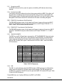
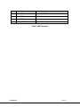
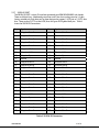
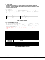
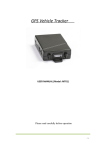
User’s Manual The most important thing we build is trust. Digital Data Processor Card (DDPC) 100-M0070X2 05/14/2009 Cobham Surveillance GMS Products 1916 Palomar Oaks Way Ste 100 Carlsbad, CA 92008 T: 760-496-0055 F: 760-496-0057 www.cobham.com/gms Table of Contents 1 2 3 4 5 6 7 Acronyms....................................................................................................................................................................... 4 Introduction ................................................................................................................................................................ 5 2.1 Key System Features ............................................................................................................................................. 5 System Overview...................................................................................................................................................... 6 Getting Started .......................................................................................................................................................... 8 4.1 Initial Checkout ........................................................................................................................................................ 8 4.1.1 AES Decryption Setup................................................................................................................................ 8 4.1.2 High Speed Data w/wo AES Decryption Setup .............................................................................. 9 4.1.3 User Data w/wo AES Decryption Setup............................................................................................. 9 4.1.4 High Throughput 4K Setup ................................................................................................................... 10 Hardware Overview ............................................................................................................................................. 12 5.1 DDPC CONNECTION DIAGRAM ................................................................................................................... 13 5.2 DDPC BACK PANEL .............................................................................................................................................. 13 5.2.1 System Active LED .................................................................................................................................... 14 5.2.2 Function Active LED................................................................................................................................. 14 5.2.3 DVB ASI IN (Asynchronous Serial Interface)............................................................................... 14 5.2.4 DVB ASI OUT (Asynchronous Serial Interface) .......................................................................... 14 5.2.5 TWO RS-232 PORTS ................................................................................................................................ 14 5.2.6 USB................................................................................................................................................................... 14 5.2.7 50 PIN IO PORT .......................................................................................................................................... 16 5.3 DDPC Top side....................................................................................................................................................... 17 5.3.1 POWER PLUG ............................................................................................................................................... 17 5.3.2 MSR Mother Board Interface .............................................................................................................. 17 Software Overview ............................................................................................................................................... 18 6.1 System Requirements ........................................................................................................................................ 18 6.2 Software Installation .......................................................................................................................................... 18 6.3 Software Functions ............................................................................................................................................. 18 6.3.1 Function AES Decryption ...................................................................................................................... 19 6.3.1.1 Function AES Decryption Buttons and Selects ................................................. 19 6.3.2 Function High-Speed Data ................................................................................................................... 20 6.3.2.1 Function High-Speed Data Buttons and Selects............................................... 21 6.3.3 Function User Data................................................................................................................................... 21 6.3.3.1 Function User Data Buttons and Selects ............................................................... 22 6.3.4 Function 4K .................................................................................................................................................. 22 6.3.4.1 Function 4K Buttons and Selects ................................................................................. 22 Specifications .......................................................................................................................................................... 23 100-M0070X2 2 of 26 www.cobham.com/gms List of Figures Figure 1 Three CH MSR w/optional BDC’s and DDPC ................................................................................................. 7 Figure 2 System Configuration for DDPC with AES Decryption only ................................................................. 8 Figure 3 System Configuration for DDPC with High Speed Data, AES Decryption optional. .................. 9 Figure 4 System Configuration for DDPC with User Data w/wo AES Decryption Setup ........................ 10 Figure 5 4K System Configuration for DDPC with 4K .............................................................................................. 11 Figure 6 Rear/Top views ......................................................................................................................................................... 12 Figure 7 Internal Logic Diagram ......................................................................................................................................... 13 Figure 8 DVB ASI in/out and Data/Control diagrams ............................................................................................... 13 Figure 9 AES Decryption Descrambling Mode ............................................................................................................ 19 Figure 10 AES Decryption Descrambling Mode ......................................................................................................... 20 Figure 11 Configure High Speed Data ............................................................................................................................. 20 Figure 12 User Data Mode .................................................................................................................................................... 21 Figure 13 4K Mode ................................................................................................................................................................... 22 List of Tables Table 1 RS-232 Connector.................................................................................................................................................... 14 Table 2 USB Connector .......................................................................................................................................................... 15 Table 3 50 PIN IO Connector .............................................................................................................................................. 16 Table 4 Power Connector ...................................................................................................................................................... 17 Table 5 MSR Mother Board Interface .............................................................................................................................. 17 List of Appendices Appendix A: Cable, DDPC to High-Speed Data out ................................................................................................... 25 Appendix B: Cable, User Data RS-232 ............................................................................................................................. 26 100-M0070X2 3 of 26 www.cobham.com/gms 1 Acronyms This section lists and describes the various acronyms used in this document. Name 16QAM 64QAM A A/V AES ABS ASI BDC COFDM CVBS D/C DDPC DVB-T FEC GUI I/O Kbaud Kbps LO Mbps MDL MDR MDT MSR MER MPEG NTSC PAL QPSK RF RX S/N SPI THD TS TX VAC VDC 100-M0070X2 Meaning 16-State Quadrature Amplitude Modulation 64-State Quadrature Amplitude Modulation Amperes Audio/Video Advanced Encryption System 32 bit Messenger Basic Scrambling 8 bit Asynchronous Serial Interface Block Down Converter Coded Orthogonal Frequency Division Multiplexing Composite Video Down-Converter Digital Data Processing Card Digital Video Broadcasting - Terrestrial Forward Error Correction Graphical User Interface Input/ Output Kilobaud per second Kilobits per second Local Oscillator Megabits per second Messenger Digital Link Messenger Digital Receiver Messenger Digital Transmitter Messenger Smart Receiver Modulation Error Rate Moving Picture Experts Group National Television System Committee Phase Alternation Line Quadrature Phase Shift Keying Radio Frequency Receiver Signal-to-Noise Ratio Parallel Transport Stream Total Harmonic Distortion DVB MPEG Transport Stream Transmitter Volts (Alternating Current) Volts (Direct Current) 4 of 26 www.cobham.com/gms 2 Introduction The GMS Digital Data Processor Card (DDPC) is a data processor with several powerful and unique features. Data can be received and transmitted by any combination of the following: ASI/SDI via BNC serial cable, and/or LVDS/LVTTL via 50-pin connector, computer communications through two RS-232 ports, and can be programmed for custom applications. The DDPC is designed to fit one of the slots of the GMS Messenger Smart Receiver (MSR) or stand-alone. This manual provides information on how to operate the DDPC as well as pertinent technical information related to the overall system. 2.1 Key System Features Applications High-Security Surveillance Applications UAV/UGV Applications Sports, POV and ENG Key Processor Features Operates with MSR ASI IN/OUT Generic Parallel I/O Powerful FPGA UP Controlled Firmware Applications High-Speed Serial Data AES Decryption User Data Extraction High Throughput 4K Custom Applications 100-M0070X2 5 of 26 www.cobham.com/gms 3 System Overview The GMS Messenger Digital Link (MDL) system utilizes a robust digital modulation system known as COFDM that provides frequency diversity and powerful Forward Error Correction (FEC) algorithms. The end result is a robust wireless link that is effective against multipath interference experienced by analog systems, and provides crisp, clear pictures in the most difficult of terrains. The MSR receives and demodulates a DVB-T signal and recovers the DVB MPEG-2 transport stream containing the digital video, audio and ancillary data. GMS offers several special functions that modify the typical A/V Transport Stream (TS). These functions include AES encryption, User Data insertion, and High-Speed generic digital data encapsulation. The encryption option has a 32-bit Advanced Encryption System (AES) to provide protection in sensitive applications. The recovered TS is decrypted by the DDPC and converted to Asynchronous Serial Interface (ASI) and SPI Parallel Transport Stream (SPI). The MDT-D can encapsulate High-Speed serial data into a standard MPEG-2 format and transmit it. The DDPC receives the demodulated MPEG-2 packet and extracts the High-Speed serial data out and converts it into LVTTL and LVDS format. User Data is applied to a normal A/V MPEG-2 stream to supply more information about the video. For example, if connected to a GPS the transmitter location could be known at any time. Without disrupting the video stream, the DDPC will extract the User Data and send it to a computer through a RS232 port. All connections to the DDPC are located on the back panel. For certain applications like HD and multiple programs in a single TS Wireless Transmission, it is desirable to have greater throughput rates. If the user can utilize more RF bandwidth (12, 14, or 16 MHz), then the 4K Option can be used to double the throughput! Often, the 4K option can provide the same throughput that can be achieved with 2K with a lower modulation format dramatically increasing the system range (+80%). If higher picture quality is desired, the same Link robustness can be achieved by switching to 4K with double the throughput which can equate to a dramatic increase in Video quality! On the receive side, the 4K option works by combining the outputs of two MSR-s. Each BDC output IF signal is split and presented to the corresponding Tuner/Demod of each MSR which processes ½ of the carriers. The reconstruction of the original TS occurs in the DDPC. External Audio/Video/Data Decoders are sold separately that support SD and HD MPEG-2 4:2:0 and/or 4:2:2, H.264, AVC, raw data, and any other format or any combination of formats can be transmitted in a transport stream. LAN IP streaming interfaces are also available from GMS to support distribution of the Wireless Audio/Video/Data anywhere in the world via the Internet. This system architecture supports single or multiple programs by looping the ASI interface to multiple Decoders. The MSR is normally used with GMS’ optional Block Down-Converters (BDC-s) to provide frequency coverage from 862 MHz to 6 GHz. GMS’ BDC-s can be mounted remotely, normally right at the antenna output (optimizing system performance) or within the MSR chassis. When remotely mounted, BDC power can be provided via the IF coax cable. The MSR’ MS Windows Control SW provides independent control of the power to each BDC. 100-M0070X2 6 of 26 www.cobham.com/gms A single MSR with internally mounted BDC-s and DDPC can support up to 3 independent antennas. With external BDC-s, each single MSR can support up to 6 independent antennas. The system automatically configures itself for inputs from 1 to 6 per MSR. Both even and odd configurations are supported. Figure 1 Three CH MSR w/optional BDC-s and DDPC The DDPC can be controlled through the MSR USB or serial port (future), and it can also be controlled separately through its own USB or serial port from its back via an IBM PC using a Window’s based control program. This program provides control 128 AES decryption key, bypass AES decryption, high-speed data settings, user data extraction and controls, and various Custom applications. Settings, if desired, need to be set only once, and then it will continue to operate even if power is lost. Some settings, i.e. the AES decryption key for security reasons, have the option of being lost when powered down. Other functions and card inserts for the MSR can be down loaded from www.cobham.com/gms. This document will only describe functions for the MSR as it applies to the DDPC. 100-M0070X2 7 of 26 www.cobham.com/gms 4 Getting Started The DDPC is pre-configured by GMS prior to shipment (based on customer requirements), thus is ready to work “right out of the box”. NOTE: Additional cables may be delivered by GMS based on customer application. Contact GMS for further information. 4.1 Initial Checkout Prior to installing a DDPC unit into the desired target environment, an initial checkout should be performed to ensure proper operation of the unit. 4.1.1 AES Decryption Setup The AES Decryption needs two BNC cables and a USB cable. A short BNC cable and USB cable is shipped with the DDPC unit. Figure 2 shows the DDPC system configuration for AES Decryption only. The steps necessary to setup the system configuration in Figure 2 are shown below. AES DECRYPTION CONFIGURATION CONTROL DVB ASI MPEG-2 OUT DVB ASI MODIFIED MPEG-2 IN DECODER BNC BNC ASI ASI IN 50 O/I LVDS/TTL I/O USB 2 RS232 CONTROL & DATA BNC ASI OUT VIDEO DDP CARD MSR SETUP AND CONTROL PC VIDEO MONITOR Figure 2 System Configuration for DDPC with AES Decryption only 1. 2. 3. 4. 5. Install MSR and other devices as their user manuals describe. Attach the short BNC cable to the MSR closest to the DB-9. Attach the other end of the short BNC cable to the ASI IN connector. Attach one end of the USB cable to the DDPC and the other end to the PC. Attach one end of BNC cable to the DDPC ASI OUT connector and the other to the Decoder. 6. Attach a video cable from the one video/audio output ports on the Decoder to a video monitor. 7. Turn on the MSR and open its supporting software. See the MSR manual (100-M0061) for specific directions. 8. Click on configuration/Down Converter, enter password, and make sure the CARD SLOT that the DDPC is in is on. 9. When turned on, click on the Apply box. Click on Configuration/Save Settings, to save. 10. Now that the System Active LED is on or blinking you can set up the DDPC. See section 6.3.1. 11. Power on and configure the rest of the devices and enjoy the video. 100-M0070X2 8 of 26 www.cobham.com/gms 4.1.2 High Speed Data w/wo AES Decryption Setup The High Speed Data with or without AES Decryption needs one BNC cables, one special High Speed Serial Cable, and a USB cable. All the cables are shipped with the DDPC unit. Figure 3 shows the DDPC system configuration for High Speed Data w/wo AES Decryption Setup. The steps necessary to setup the system configuration in Figure 3 are shown below. HIGH SPEED SERIAL DATA CONFIGURATION HIGH SPEED SERIAL DATA DVB ASI MODIFIED MPEG-2 IN BNC BNC ASI ASI IN MSR CONTROL 50 O/I LVDS/TTL I/O USB 2 RS232 CONTROL & DATA DDP CARD BNC ASI OUT SETUP AND CONTROL PC CUSTOMER EQUIPMENT Figure 3 System Configuration for DDPC with High Speed Data, AES Decryption optional. 1. 2. 3. 4. 5. Install MSR and other devices as their user manuals describe. Attach the short BNC cable to the MSR closest to the DB-9. Attach the other end of the short BNC cable to the ASI IN connector. Attach one end of the USB cable to the DDPC and the other end to the PC. Attach the 50-pin ribbon cable to the 50-pin connector. Check for keying on the inside of the connector. Note: To remove the 50-pin ribbon cable you must apply pressure to both sides of the plug and pull. There is a latch on both sides. 6. Attach the other side to a cable coming from the specialized high-speed serial data equipment. See Appendix A for pin outs. 7. Turn on the MSR and open its supporting software. See the MSR manual for specific directions 8. Click on configuration/Down Converter, enter password, and make sure the CARD SLOT that the DDPC is in is on. 9. When on click on the Apply box. Click on Configuration/Save Settings, to save. 10. Now that the System Active LED is on or blinking you can set up the DDPC. See section 6.3.1. 11. Power on and configure the rest of the devices and it is ready to go. 4.1.3 User Data w/wo AES Decryption Setup The User Data with or without AES Decryption needs two BNC cables, one special Serial Cable, and a USB cable. A short BNC cable, one special Serial Cable, and a USB cable are shipped with 100-M0070X2 9 of 26 www.cobham.com/gms the DDPC unit. Figure 4 shows the DDPC system configuration for User Data w/wo AES Decryption Setup. The steps necessary to setup the system configuration in Figure 4 are shown below. USER DATA CONFIGURATION CONTROL USER DATA DVB ASI MPEG-2 OUT DVB ASI MODIFIED MPEG-2 IN DECODER BNC BNC ASI ASI IN MSR 50 O/I LVDS/TTL I/O USB 2 RS232 CONTROL & DATA BNC ASI OUT VIDEO DDP CARD SETUP AND CONTROL PC USER DATA CONTROL UNIT VIDEO MONITOR Figure 4 System Configuration for DDPC with User Data w/wo AES Decryption Setup 1. 2. 3. 4. 5. 6. Install MSR and other devices as their user manuals describe. Attach the short BNC cable to the MSR closest to the DB-9. Attach the other end of the short BNC cable to the ASI IN connector. Attach one end of the USB cable to the DDPC and the other end to the PC. Attach the 10-pin connector to the DDPC next to the USB connector. Attach the Data DB-9 to the cable coming from the User Data Control Unit’ serial port. See Appendix B to see pin outs. 7. Attach one end of BNC cable to the DDPC ASI OUT connector and the other to the Decoder. 8. Attach a video cable from the one video/audio output ports on the Decoder to a video monitor. 9. Turn on the MSR and open its supporting software. See the MSR manual for specific directions 10. Click on configuration/Down Converter, enter password, and make sure the CARD SLOT that the DDPC is in is on. 11. When on click on the Apply box. Click on Configuration/Save Settings, to save. 12. Now that the System Active LED is on or blinking you can set up the DDPC. See section 6.3.1. 13. Power on and configure the rest of the devices and it is ready to go. 4.1.4 High Throughput 4K Setup The 4K needs two BNC cables, a USB cable, a Combiner Card one short 50-pin ribbon cable and two longer 50-pin ribbon cables. A short BNC cable and USB cable are shipped with the DDPC unit. The Combiner Card and ribbon cables are shipped with 4K option MSR-s. Figure 4 shows the DDPC system configuration for 4K Setup. The steps necessary to setup the system configuration in Figure 4 are shown below. 100-M0070X2 10 of 26 www.cobham.com/gms BNC 50 I/O ASI SPI OUT MSR SLAVE COMBINER DVB ASI BNC 50 I/O BNC 50 I/O ASI SPI OUT ASI IN LVDS/TTL I/O MSR MASTER 2 RS232 USB CTRL &DATA BNC DECODER VIDEO ASI OUT DDP CARD VIDEO MONITOR SET UP AND CONTROL PC Figure 5 4K System Configuration for DDPC with 4K 1. 2. 3. 4. 5. Install MSR and other devices as their user manuals describe. Attach the short BNC cable to the BNC connector of MSR closest. Attach the other end of the short BNC cable to the ASI IN connector. Attach one end of the USB cable to the DDPC and the other end to the PC. Attach one end of BNC cable to the DDPC ASI OUT connector and the other to the Decoder. 6. Attach a video cable from the one video/audio output ports on the Decoder to a video monitor. 7. Attach a 50-pin short ribbon cable to the J107 of Combiner Card. 8. Attach 2 long 50-pin ribbon cables to the J100 and J107 of the Combiner Card. 9. Attach the other ends of 50-pin ribbon cables to SPI OUT connectors of each MSR. 10. Turn on the MSR and open its supporting software for 4K MSR. See the MSR manual (100M0061) for specific directions. 11. Click on configuration/Down Converter, enter password, and make sure the CARD SLOT that the DDPC is in is on. 12. When turned on, click on the Apply box. Click on Configuration/Save Settings, to save. 100-M0070X2 11 of 26 www.cobham.com/gms 5 Hardware Overview The DDPC is designed to fit in one slot of the MSR or in an optional external 4”x3”x1” enclosure. All user interface connectors (RS-232, USB, ASI in/out and 50 pin LVDS/LVTTL) and two led indicators (System Active and Function Active) are located on the rear of the DDPC unit panel. When installed in the MSR, power comes from the MSR’s 12V power supply. When in an external enclosure, power comes from a 2-pin 2mm JST connector near the top. The rear and top view of the DDPC unit is illustrated in Figure 5. Rear View DVB ASI IN DVB ASI OUT 50 PIN IO PORT USB 2 RS-232 PORTS System Active LED Function Active LED Top View MSR MOTHER BOARD INTERFACE POWER PLUG Figure 6 Rear/Top views 100-M0070X2 12 of 26 www.cobham.com/gms The DDPC has a Micro-controller and an FPGA that can do highly complex computations. Its ability to accept and produce serial ASI and 44 I/O data pins make it a most versatile tool. The DDPC is protected with a 1 amp resettable fuse. The board is designed to accept 9-15 VDC input power. Power consumption is application dependant. Refer to application. The internal logic diagram is shown in figure 6. Digital Data Processor Card (DDPC) DDR RAM 1MX16X4 Parallel I/O CNTRL Microprocessor 22 LVDS OR 44 TTL RS232 GENERAL PURPOSE I/O RS232 ASI I^2C FEED BACK ASI Parallel to Serial Interface ASI OUT CNTRL CNTRL DATA FPGA XILINX SPARTAN 3(E) XC3S200 CNTRL ASI IN ASI Serial to Parallel Interface DATA J1 12V RESET I^2C FLASH 4MB XCF04S USB Figure 7 Internal Logic Diagram The DDPC fits into any slot in the MSR except #1 if diversity tuners are loaded. The MSR’s “switched 12 VDC” must be turned on for the card slot that the DDPC is in. The MSR can talk to the DDPC through the 80-pin connector via I2C port on the connector. COMPUTER CONTROL HIGH SPEED DATA OUT MSR DVB ASI IN RS-232 CONTROL AND USER DATA 10 Pin DDP CARD USB DVB ASI OUT DIG I/O DECODER/VIDEO BNC DDPC CONNECTION DIAGRAM Figure 7 shows a comprehensive connection diagram for the DDPC. See section 4.1 for individual configuration setups. In the following section will explain the connections and the LEDs used by the DDPC. 50 Pin BNC 5.1 Figure 8 DVB ASI in/out and Data/Control diagrams 5.2 DDPC BACK PANEL Located on the back panel are all interface connectors (two RS-232, USB, ASI IN/OUT and 50 pin LVDS/LVTTL) and two status LED indicators (System Active and Function Active). See Figure 5 Rear View for their location. 100-M0070X2 13 of 26 www.cobham.com/gms 5.2.1 System Active LED A solid LED indicates that the system has power, and a blinking LED indicates data is being received. 5.2.2 Function Active LED The Function Active LED indicates that data is being processed by the DDPC. If the light is off then the data is not being processed and is leaving the same as it enters. For example if the AES Decryption mode is turned on and the Function Active LED is on, the ASI stream is being decrypted. If the Function Active LED is off then the ASI stream is not being decrypted. 5.2.3 DVB ASI IN (Asynchronous Serial Interface) The DVB MPEG transport stream in high-speed serial format is input on this port via a BNC-F connector. The DVB ASI transport stream must conform to the ETSI Spec TR101891 V1.1.1 (2001 – 2002). Then the data is fed into the FPGA. 5.2.4 DVB ASI OUT (Asynchronous Serial Interface) The DVB MPEG transport stream in high-speed serial format is output on this port via a BNC-F connector. The DVB ASI transport stream conforms to ETSI Spec TR101891 V1.1.1 (2001 – 2002). 5.2.5 TWO RS-232 PORTS The DDPC has two RS-232 serial ports connected to a JST SM10B-SRSS-TB 10 pin right angle connector. The control (CNTL) port is used to directly control the DDPC. You will be able to interact with the software GUI and down load firmware updates. The MCU shares this port with the USB. The data (DATA) port is used to extract User Data. Table 1 shows the Two RS232 Connections. Pin 1 2 3 4 5 6 7 8 9 10 Signal Gnd CNTL Rx CNTL Tx Gnd DATA Tx DATA Rx Gnd SDA SCL Gnd Description Ground Connection Transmit Control Receive Control Ground Connection Transmit User Data Receive User Data Ground Connection I2C Data I2C Clock Ground Connection Table 1 RS-232 Connector 5.2.6 USB The USB-1 is used to directly control the DDPC through a USB-B connector. It will be able to interact with the software GUI and down load firmware updates. The USB will need to be installed into a computer. The MCU shares this port with the RS-232 control (CNTL) port. Table 2 shows the USB Connections. To load USB Drivers see “Loading USB Drivers for DDPC” on CD-ROM. 100-M0070X2 14 of 26 www.cobham.com/gms Pin Signal 1 5V Description 5V POWER 2 USBDM D- 3 USBDP D+ 4 USB GND GND Table 2 USB Connector 100-M0070X2 15 of 26 www.cobham.com/gms 5.2.7 50 PIN IO PORT The 50 PIN IO PORT is a data IO interface connected to an ERNI 054596 0.05-inch header. There are 44 data lines, 4 dedicated ground lines and 2 lines that can be ground or 3.3 volts, factory settable only. Each data pair has been designed to support 1 LVDS pair or 2 LVTTL data lines. There are four (LVTTL or two LVDS) lines that go to FPGA global clock pins. Table 3 shows the 50 PIN IO Connections. Pin Signal Pin Signal 1 1Negative Data 0 2 1Positive Data 0 3 1Negative Data 1 4 1Positive Data 1 5 1Negative Data 2 6 1Positive Data 2 7 1Negative Data 3 7 1Positive Data 3 9 1Negative Data 4 10 1Positive Data 4 11 1Negative Clock 12 1Positive Clock 13 1Negative Valid 14 1Positive Valid 15 1Negative Sync 16 1Positive Sync 17 Ground 18 Ground 19 1Negative Data 5 20 1Positive Data 5 21 1Negative Data 6 22 1Positive Data 6 23 1Negative Data 7 24 1Positive Data 7 25 Ground/3.3V 26 Ground/3.3V 27 2Negative Data 0 28 2Positive Data 0 29 2Negative Data 1 30 2Positive Data 1 31 2Negative Data 2 32 2Positive Data 2 33 2Negative Data 3 34 2Positive Data 3 35 2Negative Data 4 36 2Positive Data 4 37 2Negative Clock 38 2Positive Clock 39 2Negative Valid 40 2Positive Valid 41 2Negative Sync 42 2Positive Sync 43 Ground 44 Ground 45 2Negative Data 5 46 2Positive Data 5 47 2Negative Data 6 48 2Positive Data 6 49 2Negative Data 7 50 2Positive Data 7 Table 3 50 PIN IO Connector 100-M0070X2 16 of 26 www.cobham.com/gms 5.3 DDPC Top side Located near the front of the DDPC are the POWER PLUG and the MSR MOTHER BOARD INTERFACE, these two connectors supply power and I2C control from the MSR Mother Board (future). See Figure 5 Top View. 5.3.1 POWER PLUG The POWER PLUG connector is a JST B2B-PH-SMT-TBT 2MM pitch. It can receive 12 volts from a different source than the MSR for stand-alone cases. Table 4 shows the POWER PLUG Connections. Pin 1 2 Signal 12V Gnd Description Power Connection Ground Connection Table 4 Power Connector 5.3.2 MSR Mother Board Interface The MSR MOTHER BOARD INTERFACE edge connector connects the DDPC to the MSR 80 pin SAMTEC MEC1-140-02-F-D-A. This gives the DDPC power and I2C control. The connector also passes through diversity tuner data from one tuner to the next. Table 5 shows the MSR MOTHER BOARD INTERFACE Connections. NOTE: The DDPC should not be placed in slot 1 if turners are used in the same MSR. PIN 1 through 16 17 through 26 27 and 28 31 and 32 49 50 51 52 through 56 61 through 66 71 through 76 57 through 60 57 through 70 57 through 80 SIGNAL Pass tuner diversity data to No Connect Pass tuner diversity data to Edge Connector Key Pins, No Connect I2C Data (SDA) Reset I2C Clock (SCL) PIN 29 through 46 47 and 48 Ground Isolated 1.8V Isolated 5V MSR Source 12V Table 5 MSR Mother Board Interface 100-M0070X2 17 of 26 www.cobham.com/gms 6 Software Overview Configuration, control and monitoring of the DDPC unit can be implemented by using the Windows based control program supplied for each application. This program provides control of the AES decryption key and mode, high-speed data lost connection byte, and other needed settings. The DDPC can be setup once and will continue to run without flaw even when powered down, except when AES Decryption is set to “AES, NEVER Store the key in the DDP” mode, or the transmitter has changes certain settings explained later in this section. No other interface will be needed. 6.1 System Requirements The DDPC Control program has been developed and tested on Microsoft Windows 2000 and Windows XP. 6.2 Software Installation The following instructions outline the installation process for DDPC Control program: 1. Insert provided CD-ROM into computer CD drive. 2. Run ‘setup.exe’ file. This will launch the GMS_DDPC setup program and several initial setup files will begin to be copied into the computer. 3. After the initial setup files are copied, the GMS_ DDPC setup program will prompt the user to close any applications that are running. Once all other programs are exited, click on the ‘OK’ button. 4. The GMS_ DDPC setup program will prompt the user to click on the ‘computer icon’ button to begin installation. If desired, the user can change the destination directory from the default. Click on the ‘computer icon’ button. 5. The GMS_ DDPC setup program will then prompt the user to ‘Choose Program Group’. If desired, the user can change the program group from the default. Click on the ‘Continue’ button. 6. After installing the DDPC program, the setup program will display a window indicating the setup was completed successfully. Click ‘OK’. To load USB Drivers see “Loading USB Drivers for DDPC” on CD-ROM. 6.3 Software Functions The DDPC control software provides the user access to many different configuration and control options. When the program is launched the specific configuration screen will appear. Select the serial port and a few options and the DDPC will be ready to run. The DDPC has the following configurations: 128 bit AES Decryption, AES Encryption, and HighSpeed Data from MPEG-2 transport stream. User Data is planned in the near future. These functions can be used alone or combined. For other configurations contact us at www.cobham.com/gms. 100-M0070X2 18 of 26 www.cobham.com/gms 6.3.1 Function AES Decryption When the program is launched, the screen shown in Figure 8 is displayed. The user should first select the serial port the computer is connected to via the Serial Port Selector and connection region. To configure the DDPC, the user must select a Descrambling mode, type in the Descrambling key, if in AES mode, and then click on Apply. Click on update to store these settings after powering off. The following section explains the various functions. Figure 9 AES Decryption Descrambling Mode 6.3.1.1 Function AES Decryption Buttons and Selects Com Port Selection: Select the COM port that the DDPC is connected to. Query Button: Clicking on this button will set all the fields to the current operation mode, except the Descrambling Key. Update Button: Load the DDPC with the new Descrambling Mode and Descrambling Key. This will save the settings and take a minute to reboot your DDPC. Descrambling mode: As figure 9 shows, this box selects three different modes. Bypass mode: This mode does not do any AES Decryption. All other functions are not affected. AES, NEVER Store the key in the DDP mode: This mode does AES Decryption but the Decryption key must be reloaded every time it is powered off. This is for higher security. AES, Store the key in DDP mode: This mode does AES Decryption and the DDPC remembers the Decryption key so when the DDPC is powered on it will come up working. Descrambling key: This box loads the decryption key. The Descrambling mode must be set to an AES mode before this input is available. 100-M0070X2 19 of 26 www.cobham.com/gms Figure 10 AES Decryption Descrambling Mode 6.3.2 Function High-Speed Data When this program is launched the screen shown in figure 10 is shown. The user should first select the serial port the computer is connected to via the Serial Port Selector and connection region. There is no need to change any settings to make the DDPC function in High-Speed Data mode. The Option menu will only be enabled if you have purchased the AES Decryption option. See AES Decryption for a full explanation of the settings. To change High-Speed Data you must set all functions as desired, click on Apply, and click on Save. The following section explains the various functions. Figure 11 Configure High Speed Data 100-M0070X2 20 of 26 www.cobham.com/gms 6.3.2.1 Function High-Speed Data Buttons and Selects Com Port Selection: Select the COM port that the DDPC is connected to. Reset Button: Clicking on this button re-initializes the DDPC FPGA. Query Button: Clicking on this button will set all the fields to the current operation mode, except the Descrambling Key. Apply Button: Load the DDPC with the new Descrambling Mode and Descrambling Key. Save Button: Clicking this button will save the settings to the DDPC so when power is recycled the DDPC will remember the last settings. Value of Data when No Link: This box loads the No Link byte. This byte will be outputted when the DDPC is no longer receiving valid data through the link. PCR PID: This box loads the 13-bit PCR PID into the DDPC. The PCR PID of the DDPC must match the High-Speed Data transmitter’s PCR PID. Data PID: This box loads the 13-bit Data PID into the DDPC. The Data PID of the DDPC must match the High-Speed Data transmitter’s Data PID. For information on all other buttons refer to the AES Decryption function section. 6.3.3 Function User Data When this program is launched the screen will look a lot like the previous functions. The user should first select the serial port the computer is connected to via the Serial Port Selector and connection region. To enable the User Data click Insert User Data button. The PID should match the one in the Transmitter. To change User Data you must set all functions as desired, click on Apply, and click on Save. Figure 12 User Data Mode 100-M0070X2 21 of 26 www.cobham.com/gms 6.3.3.1 Function User Data Buttons and Selects Com Port Selection: Select the COM port that the DDPC is connected to. Reset Button: Clicking on this button re-initializes the DDPC FPGA. Query Button: Clicking on this button will set all the fields to the current operation mode, except the Descrambling Key. Apply Button: Load the DDPC with the new Descrambling Mode and Descrambling Key. Save Button: Clicking this button will save the settings to the DDPC so when power is recycled the DDPC will remember the last settings. User Data PID has two selections: OFF and Insert User Data. The value of PID can be changed in the PID window. 6.3.4 Function 4K When the program is launched, the screen shown in Figure 13 is displayed. The user should first select the serial port the computer is connected to via the Serial Port Selector and connection region. To configure the DDPC, the user must enable 4K mode, and then click on Apply. Click on Save to store these settings after powering off. The following section explains the various functions. Figure 13 4K Mode 6.3.4.1 Function 4K Buttons and Selects Com Port Selection: Select the COM port that the DDPC is connected to. 100-M0070X2 22 of 26 www.cobham.com/gms Reset Button: Clicking on this button re-initializes the DDPC FPGA. Query Button: Clicking on this button will set all the fields to the current operation mode, except the Descrambling Key. Apply Button: Load the DDPC with the new Descrambling Mode and Descrambling Key. Save Button: Clicking this button will save the settings to the DDPC so when power is recycled the DDPC will remember the last settings. 4K Mode: This box indicates the mode of the received signal (Red for 2K and green for 4K). 7 Specifications The following sections outline the overall specifications for the DDPC unit. Main Board Processors Xilinx FPGA AVR Micro-controller Interfaces Control 2 RS-232C via JST SM10B-SRSS-TB 10 pin USB-1 via USB-B Connector MSR I2C via 80 pin edge connector, mates with SAMTEC MEC1-140-02-FD-A Transport/Data Stream in/out ASI in via BNC-F Connector 50 Pin I/O Micro-Header, ERNI 054596 0.05-inch Connector ASI out via BNC-F Connector DC Power 2 pin, AMP 350786-2 Connector MSR via 80 pin edge connector, mates with SAMTEC MEC1-140-02-F-D-A AC Power (Optional with external in-line cable assembly) Controls & Status “ACTIVE” – Provides indication that system is powered and processing data “FUNCTION” – Provides indication that the special function is active Full DDPC System control and status is accessed through either its RS-232C or USB1 control ports via the supplied MS Windows based control application. Physical Size (inches): 3.8 x 2.78 x 0.5 (Less Connectors) (cm): 9.65 x 7.06 x 1.27 Weight: 2.0 oz (56.5 grams) Environmental: Operational Temperature: -10 to 70 deg C Humidity: Up to 100% non-condensing DC Power DC Voltage Range: 9 -15V Power Consumption: 4.8 Watts 100-M0070X2 23 of 26 www.cobham.com/gms Case (go to www.cobham.com/gms for details) MSR (Sold Separately) See separate data sheets Rack-Mount (Sold Separately) 100-M0070X2 24 of 26 www.cobham.com/gms Appendix A: Cable, DDPC to High-Speed Data out 100-M0070X2 25 of 26 www.cobham.com/gms Appendix B: Cable, User Data RS-232 100-M0070X2 26 of 26 www.cobham.com/gms