1
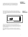
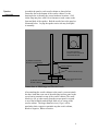
EMINENT
TECHNOLOGY
INCORPORATED
LFT-8b
HYBRID LINEAR FIELD TRANSDUCER LOUDSPEAKER
®
REFERENCE MANUAL
Revised: 10/30/07
Eminent Technology, Inc. 225 East Palmer Street Tallahassee, Florida 32301
Phone: (850) 575-5655 FAX: (850) 224-5999 Email: [email protected]
Website: www.eminent-tech.com
Extremely strong magnetic fields
are present at and around this
loudspeaker. Devices that are
adversely affected by high levels of
magnetic flux, such as television
sets and pacemakers, should be
kept at least three feet away from
each speaker. Also, keep in mind
when any ferrous objects are
brought close to the speakers.
Hold steel tools securely when
setting up and adjusting the LFT8b, to prevent a hex key or
screwdriver from slipping from
your hand and damaging the
Mylar diaphragm.
ATTENTION:
STRONG
MAGNETIC
FIELDS
_____________
2
TABLE OF CONTENTS
Installation of the LFT-8b........................................................... 5
Unpacking the Speakers............................................................. 5
Speaker Assembly...................................................................... 6
Positioning the Speakers in the Listening Room........................7
Imaging....................................................................................... 7
The Tweeter Level Control........................................................ 8
Amplifier Requirements............................................................. 8
Bi-Wiring and Bi-Amping..........................................................9
Bi-Amping.................................................................................. 9
Technical Description.................................................................10
Electrostatic Loudspeakers....................................................... 11
Planar Magnetic Loudspeakers................................................ 12
Ribbon Loudspeakers............................................................... 13
Evaluating Earlier Approaches................................................. 14
Electrostatics............................................................................ 14
Planar Magnetics...................................................................... 14
Ribbons..................................................................................... 14
The Linear Field Transducer.................................................... 16
Diaphragm Construction.......................................................... 16
The Magnet/Frame Structure....................................................16
Panel Frequencies..................................................................... 18
General Specifications................................................................ 19
LFT-8b Impedance Curves........................................................20
LFT-8b Impedance Data............................................................21
Crossover Information............................................................... 22
Square Wave Performance........................................................ 23
Frequency Response Curve....................................................... 24
LFT-8b Panel Specifications......................................................25
Mid Range Panel Design............................................................ 26
LFT-8b Woofer Specifications.................................................. 27
Additional Woofer Specifications............................................. 28
Woofer Design.............................................................................29
3
Woofer Enclosure....................................................................... 30
Warranty..................................................................................... 31
Appendix A – Hex Cam Spacer Installation............................ 33
Appendix B – Tweeter Diaphragm Replacement.................... 36
4
Installation of
the LFT-8b
A complete technical description of the LFT-8b is included in this
manual and begins on page 10. It is recommended that you become
familiar with this information because an understanding of the LFT
principals will assist you in the proper set up of these loudspeakers.
The LFT-8b is shipped in 3 boxes. The larger square box contains the two
woofer cabinets. The 2 long rectangular boxes contain the panels and grills. To
remove the panels position the box on its side and open the end of the shipping
carton. Remove the padding from the bottom and slide the speaker from the box
as shown below.
Open
After removing the speaker from its carton it can be leaned against a wall
standing up or placed with the front face of the speaker flat on the carpet. Then
the bubble wrap should be removed. The wrap also holds the grill cloth (covered
by a large cardboard sheet) to the speaker. After the wrap is removed these will
separate from the speaker.
Do not attempt to remove or loosen hardware on the drivers themselves.
The magnets are held together under great force and personal injury could
result.
5
Unpacking the
Speakers
Speaker
Assembly
Assemble the panel to each woofer cabinet as shown below.
Fasten the feet to the bottom of the woofer cabinet. Use the
drawing below to identify the correct hardware locations. Grill
cloths snap into place with Velcro fasteners at each corner on the
front and back of the speaker. Bolt the woofer box to the panel as
illustrated below. Laying the speaker on its side may be helpful
in assembly.
Front View Showing
Position of The Five 8X3/4
Sheet Metal Screws
(5) #8X3/4 Sheet Metal
Screws In Front Of Panel
Location Of Terminal Board
Woofer Cabinet
Sheet metal Screw (2)
(4) #8X3/4 Sheet Metal
Screws In Bottom
10-32 x 3/4 Socket Head
Screw (4)
Connections to Mid-Range and Tweeter Panels
After attaching the woofer cabinets to the panels, you must attach
the three leads that come out of the mid-range/tweeter panel to the
screw barrier terminals on top of the woofer cabinets. The small
black wire (18 ga.) that comes from the tweeter panel is secured
to on of the terminals marked High, Med or Low on top of the
woofer cabinet. The larger diameter wires (12 ga.) will be
attached to their respective terminals atop the woofer cabinet,
Black to Negative, White to Positive.
6
Speaker placement is critical for correct imaging, frequency
balance, low frequency performance, and efficiency.
The LFT-8b speakers are a mirror image pair and should be set up
with the tweeter panels to the inside.
Positioning
the Speakers
in the
Listening
Room
Low frequency performance in particular can be determined by
the shape of the room and the speaker's distance from the wall
immediately behind them. Typically, the optimal distance
between the LFT’s and the rear wall is 1 to 5 feet in an average
room.
The overall frequency balance of the LFT-8b is somewhat
affected by the degree to which the speakers are toed in toward
the central listening position. The on-axis frequency response of
the LFT-8b is essentially flat, and it is often best to position the
speakers so that the main listening position is about on axis with
each speaker. Slight mid-range frequency balance changes can be
obtained by pointing the speakers slightly away from the listening
position. Adjusting the speakers’ degree of vertical tilt with the
pointed feet can also alter this balance.
Overall imaging depends primarily on the distance separating the
two speakers relative to their distance from the preferred listening
position; it is also affected by the degree of toe-in. We cannot
accurately predict what will work best in your listening room, and
can suggest only that you begin with the drawing on the previous
page as a starting point or general guideline. Keep in mind that
the parameters that affect frequency balance also tend to affect
imaging properties, and vice versa, so it is best to adjust speaker
placement in small increments and to note carefully all of the
changes effected by each shift in position before proceeding
further.
7
Imaging
The Tweeter
Level Control
The high frequency performance of the LFT’s can be tailored with the
tweeter level control. The high frequency performance of the LFT-8b is
adjusted with the tweeter level control. There are three tweeter level
positions: High, Mid and Low. These levels adjust the tweeter output
in approximately 3 dB increments. It is best to start with the tweeter
level set to Low, position the speakers for the best overall frequency
balance, and then decide if more high frequency energy is needed.
Amplifier
Requirements
The LFT-8b is wired for 8-ohm operation and is appropriate for use
with most moderately powered tube and solid-state amplifiers. The
efficiency is 84dB with a 2.83-volt drive (1 “8” ohm watt). The
efficiency rating is lower than average. However, the LFT-8b radiates
a planar wave front, and as such, on axis its apparent efficiency at the
listening position is higher than the numerical rating implies. The LFT8b has a minimum rating of 75 watts per side, tube or solid state. It can
handle “music power” levels (short term burst) of 300 watts or more
with out difficulty. The largest recommended amplifier size for the
LFT-8b is 200 watts.
The LFT-8b does not require a high current amplifier. A receiver may
be used if it has sufficient power. Tube amplifiers should be used with
the 8-ohm tap.
8
The LFT-8b is configured to allow bi-wiring or bi-amping with a
minimum of trouble.
Bi-Wiring and
Bi-Amping
Bi-wiring simply means connecting a single stereo amplifier (or two
mono amps) to a pair of speakers by using two pairs of speaker cables.
Connect the hot and ground conductors of a pair of cables to the same
output terminals on one channel of the amplifier; the other ends are
connected to the separate woofer and mid/tweeter inputs of the LFT-8b
(All speaker cables should be the same length). The effects of biwiring tend to be subtle; the slight improvement may be worth the
relatively modest cost of an extra pair or speaker cables. Bi-wiring also
permits experimenting with different types of cables for the two inputs;
you may find that one type is best suited for bass performance, while
another works best on the mid/treble side.
Bi-amping requires and additional stereo amplifier or pair of mono
amps. You will also need some means of insuring that only the desired
portion of the frequency range reaches each amplifier. The simplest
way to accomplish this is with an external electronic crossover;
however, this can also be done by hard-wiring low-pass and high-pass
filters into the inputs of the bass/mid and treble amplifiers, respectively.
For the low/ frequency amp, a 180Hz low-pass filter (6 dB/octave) is
required; for the mid/treble amp, a 180Hz. high-pass filter (also 6
dB/octave) is required. If you wish to pursue this method, your dealer
or the manufacturer of your amplifiers should be able to help you
determine the specific parts necessary. Note that you will also need a
level control on either one of the stereo amps or on the crossover,
regardless of which approach you take to bi-amping. Contact Eminent
Technology or refer to the schematic in the back of this manual to
modify the crossover for proper speaker operation.
9
Bi-Amping
Technical
Description
The Eminent Technology Linear Field
Transducer is a full-range, push-pull, dynamic
planar loudspeaker. In a sense, it is the
magnetic equivalent of a push-pull electrostatic
loudspeaker, differing in that it requires no
step-up transformer or bias voltage, and that
the audio signal is applied directly to its
diaphragm.
The LFT-VIII
To fully understand the strengths of the LFT design, one must
first consider the design and operation of this speaker's three most
notable antecedents: the push-pull electrostatic loudspeaker
(ESL); the traditional, single-ended planar magnetic loudspeaker,
and the ribbon loudspeaker.
10
The electrostatic starts with a very thin (half mil or less)
diaphragm made of Mylar or a similar material, to which a light
coating of mildly conductive substance such as graphite has been
applied. This diaphragm is suspended on a rigid frame and
sandwiched between two stationary conductive grids (usually
perforated metal plates) called stators.
FRAME
FRONT
STATOR
REAR STATOR
[PERFORATED
METAL PLATE]
CONDUCTIVE
DIAPHRAM
TO BIAS
VOLTAGE
SUPPLY
RESISTOR
TO
AMPLIFIER
TRANSFORMER
-+
PUSH-PULL ELECTROSTATIC
[TOP VIEW CROSS-SECTION]
Spacing exaggerated to show detail
A DC charge of high voltage (in the thousands of volts) but very
low current, known as the bias voltage, is applied to the
conductive diaphragm and kept constant. A step-up transformer
is introduced to increase the usable voltage of the amplifier's
output (while simultaneously decreasing the current), and the two
ends of the transformer's output coil are connected to the two
stators.
As the amplifier produces a continuously varying AC voltage,
(the amplified music signal), the charge on the two stators will
also continuously change in synchronization with the music; and
since the two stators are connected to two different ends of the
transformer's output, one stator will take on a predominantly
negative charge at the same time and to the same extent that the
other stator takes on a predominantly positive charge. The
constant-charge diaphragm will thus undergo a continuously
changing state of attraction to and repulsion from the two stators
as their polarization changes, and it is this motion that excites the
air to the front and rear of the speaker and produces sound.
11
Electrostatic
Loudspeakers
Planar Magnetic
Loudspeakers
The traditional planar magnetic also starts with a thin Mylar
diaphragm, one side of which is coated with adhesive and fitted
with an aluminum wire voice grid, (analogous to the voice coil of
a conventional cone driver). The diaphragm is held taut in a
metal frame. On the front of this frame is a large sheet of
perforated metal, to which rows of vertically aligned strip
magnets have been fastened.
FRAME
DIAPHRAM
S
PERMANENT
STRIP
MAGNETS
N
VOICE GRID
[ACTUALLY A
CONTINUIOS LOOP]
S
N
PERFORATED
METAL
SHEET
S
-
TO AMPLIFIER
+
SINGLE-ENDED PLANAR MAGNETIC
[T OP VIEW CROSS-SECT ION]
Spacing exaggerated to show detail
From there, the operation of a single-ended planar magnetic
loudspeaker is remarkably similar to that of a conventional cone
driver: The amplifier's output is sent directly through the voice
grid and, because it is suspended within a stationary magnetic
field, the grid moves back and forth within that field in
synchronization with the AC voltage that is the amplified music
signal. Since the voice grid is permanently fastened to a taut
diaphragm, the diaphragm also moves in synchronization with the
music signal, exciting the air and producing sound.
12
The third and final antecedent to consider is the ribbon: a
distinctly different sort of transducer, but one that is similar (in
principle, at least) to the single-ended planar magnetic. The
ribbon’s primary distinction is that its “diaphragm” and “voice
element” are one and the same.
Ribbon
Loudspeakers
A ribbon driver is based on a long, narrow strip of conductive
material; in practice, thus far, all true ribbons have used a strip of
very thin corrugated aluminum for this purpose. The two ends of
this strip are electrically connected to the amplifier’s output, and
are physically anchored such that the strip is suspended within a
stationary magnetic field--with said magnets positioned at the
edges of the strip.
N
ALUMINUM
RIBBON
ELEMENT
PERMANENT MAGNET
_
TO AMPLIFIER
[LEADS CONNECTED TO
TOP AND BOTTOM OF
RIBBON ELEMENT]
+
S
PERMANENT MAGNET
RIBBON DRIVER
[TOP VIEW CROSS-SECTION]
The operating principle is straightforward from there: the
amplifier’s output passes directly through the aluminum strip-which, because it is suspended within a permanent magnetic field,
moves back and forth in synchronization with the signal,
producing sound.
13
Evaluating Not surprisingly, each of the approaches described above has its own
unique set of pros and cons. The electrostatic, because its diaphragm is
Earlier
Approaches so thin and light, offers exceptionally good transient response and
Electrostatics
reproduction of subtle, low-level musical detail. And, because it is a true
push-pull device (i.e., its diaphragm is, by design, driven from both the
front and the rear), the ESL operates in a linear fashion. Typically, gross
distortion results only when the driving amplifier clips into the speaker,
or when, in an attempt to play the speaker louder than its design allows,
its step-up transformer reaches a point of saturation.
On the negative side of the ledger, the ESL does require passing the
amplified musical signal through a transformer, which can introduce its
own colorations and non-linearities. Also, some ESLs are prone to a
condition known as arcing: Under the conditions of stress induced by
playing an ESL loudly, it is not uncommon for an electrical spark to jump
between one stator and the diaphragm (a phenomenon exactly analogous
to lightning), burning a minute hole in the diaphragm and, over time,
ruining it.
Planar
Magnetics
As for the planar magnetic, its strengths are similar to those of the ESL-although the addition of several feet of wire and an adhesive coat make
for a somewhat more massive diaphragm, limiting this design’s transient
capabilities by comparison. But the planar magnetic requires no step-up
transformer or bias voltage supply, and it has the added benefit of being
an extremely manageable load for most amplifiers. However, the most
specific drawback of the traditional planar magnetic is that it is a singleended (as opposed to push-pull) device: As the diaphragm’s physical
excursion increases, the voice grid moves further away from its optimal
location within the permanent magnetic field (at least in one direction).
Thus, at the very instant when this speaker is called upon to reproduce
large-amplitude waveforms, it is least able to do so without distortion.
Ribbons
In many ways, a ribbon driver can be an excellent performer: the moving
element (the “ribbon” itself) is extremely light, allowing good “speed”
and transient performance as well as freedom from coloration. And there
is no significant physical structure on either side of the ribbon’s radiating
pattern. The ribbon’s main problem is not one of performance but of
application: it cannot be used to reproduce low frequencies. To create a
moving element large enough to generate frequencies lower than a few
hundred Hz would mean moving opposing magnetic poles so far apart
that they would no longer exert a sufficient magnetic field over the entire
area of the ribbon.
14
Also, when a ribbon is operated at frequencies approaching the
element’s own resonant frequency (which is naturally quite low,
due to its high compliance), the ribbon element stretches and
“bows” to a point where it is no longer within the magnetic gap.
To get around either of these problems means to move the
permanent magnet structure from the edges of the element to one
entire side of the element, and/or to bond the element to a “host”
diaphragm, such as a sheet of Mylar, and to clamp that diaphragm
around its perimeter. In either case the driver is no longer a
ribbon; it is, in fact, a planar magnetic. To date, no one has
succeeded in creating a full range ribbon loudspeaker.
15
The Linear
Field
Transducer
Diaphragm
Construction
The
Magnet/Frame
Structure
Eminent Technology’s Linear Field Transducer, introduced
as the LFT, represents a new approach to the design and
construction of a high-quality loudspeaker*. It builds on the
strengths of the above designs while eliminating many of their
drawbacks.
The construction of the LFT –8b begins by laminating a very thin
sheet of aluminum foil to a half-mil-thick sheet of Mylar. A voice
grid pattern, created by means of CAD (Computer-Aided Design)
technology, is silk-screened onto the foil side; the remainder of
the aluminum--the part not covered by ink from the silk-screening
is chemically etched away, in a manner similar to the etching of
traces on a printed-circuit board. The ink is then washed away,
leaving a voice grid of near-perfect uniformity. This technique
results in a diaphragm/voice coil grid that is still less than one mil
in total thickness, and also permits relatively narrow spaces
between the individual traces, so the diaphragm can be evenly
driven over its entire surface.
The magnet/frame structure developed for the LFT-8b is also
unique. Eminent Technology builds its strip magnets into
individual steel channels, the size and shape of which have been
carefully designed to help “focus” the magnetic flux lines and
concentrate the strength of the magnetic field on the appropriate
area of the diaphragm/voice grid. These channels are then welded
to steel crossbars, which in turn are bolted to the frame that holds
the diaphragm in place.
Interestingly, one of the biggest challenges faced in creating a true
push-pull dynamic speaker was not a design consideration but
rather a matter of construction difficulty: to assemble a perfectly
rigid structure with very powerful permanent magnets at the front
and the rear, both sides opposing each other with tremendous
force. It was not until Eminent Technology developed a special
method for this assembly procedure that the Linear Field
Transducer became a reality.
* The design and construction of the LFT is patented.
16
By applying such new techniques to planar loudspeaker
construction, Eminent Technology has been able to eliminate
many of the flaws inherent in earlier designs. The use of a welded
channel-and-crossbar frame dispenses with the need for
perforated sheet metal (an “off-the-shelf” material presumably
used for reasons of economy and ease of manufacture.) thus
greatly improving dispersion, especially at high frequencies.
FRAME
DIAPHRAM
N
S
PERMANENT
STRIP
MAGNETS
N
S
VOICE GRID
CONTINUOUS
LOOPS
N
STEEL CROSS
BAR
S
N
STEEL
CHANNELS
_
TO AMPLIFIER
S
+
LINEAR FIELD TRANSDUCER
[T OP VIEW CROSS-SECT ION]
Spacing exaggerated to show detail
Since it is now possible to have a powerful, precisely aligned
magnet structure on both sides of the diaphragm, true push-pull
operation has been achieved: Regardless of the degree of
excursion the diaphragm undergoes, the voice element is always
optimally positioned within the magnetic field. The result is
extremely linear performance throughout the audible range, with a
profound increase in dynamic range and an absolute minimum of
distortion.
17
Panel
Frequencies
Each LFT-8b has two individual driver panels and a cone type
woofer. The placement of the individual drivers is shown in the
following diagram.
10 KHz and above
180 to 10 KHz
To 180 Hz
18
Technical
information
General Specifications:
Power Requirements
75 Watts minimum
Sensitivity
84 dB (pink noise, 20 - 20kH) at 1
watt/1 meter (2.83 V)
Frequency Response
25 Hz-50 kHz ±4 dB (typical room)
Phase Accuracy
± 20˚ 100 Hz-31 kHz
High Frequency Level
Flat, - 6dB, -12dB at 20kHz smooth
roll off
Impedance
8 Ohm rating
Maximum SPL
105 dB at 1 meter
Dimensions
13” wide by 60” high by 1” thick
Shipping Weight
90.5 lbs. Each
Warranty
3 years parts, 1 year labor
Available Finishes
Oak, Walnut, Black Painted Oak
19
Technical
information
LFT-8b Impedance Curves
The LFT-8b impedance is shown below. The impedance
generally averages much higher than 8 ohms. This means that the
speaker does not require a high current amplifier. Because of the
lower than average efficiency you will still need an amplifier with
a fairly high power rating (75 watts per channel or more). If an
amplifier clips into the speaker it will probably be due to a voltage
limitation.
20
Technical
information
LFT-8b Impedance Data
The impedance curves shown below are for the woofer and mid-range/tweeter
inputs measured individually. The woofer curve shows an impedance
minimum at 75Hz (10 ohms) and a steady rise above 100 Hz due to series
inductance. The mid-range and tweeter section impedance curves trends down
through the frequency range. Without the crossover in place, both the midrange and tweeter panels have flat impedance curves (the mid-range impedance
is 11 ohms and the tweeter impedance is 7.5 ohms).
With the woofer section in parallel with the mid-range/tweeter section, the
impedance curve becomes essentially flat with a minimum of about 7 ohms
occurring around 75 Hz and a maximum of 20 ohms at 50 kHz. The 20-ohm
peak is with the tweeter in its low output position. When the tweeter level is
set to the high position, its impedance will drop to about 10 ohms at very high
frequencies. The speaker should be considered as an “easy” 8-ohm load
having only very small reactive components.
21
Technical
Information
Crossover Information
LFT-8b Crossover Schematic
LFT-8b Crossover Physical Layout
22
Technical
Information
Square Wave Performance
The square wave performance of the LFT-8b is shown below at different
frequencies. Measurements were made in a normal listening room, and the
microphone position was optimized for each frequency. In order for a loudspeaker
to reproduce a square wave, it must have good frequency response, phase response,
impulse response and transient response. We only know of a handful of speakers
that can reproduce square waves, and most speaker companies do not want to discuss
square wave performance at all.
23
Technical
Information
Frequency Response
1/3 Octave, One Watt, One Meter
24
Technical
Information
LFT-8b Panel Specifications
Magnet Type
Ceramic 8
Mid-range Diaphragm area
126 sq in
Foil Thickness
.00033
Mylar Thickness
.0005
Laminate Adhesive Thickness
.00015
Gap Between Conductors
.03
Peak-to-Peak Diaphragm
.180
Displacement
Tweeter Diaphragm area
10 sq in
Tweeter Peak to Peak
Displacement
.050
25
Technical
information
Mid-Range Panel Design
Do not attempt to disassemble these panels. The steel frame is preventing the
panel from collapsing on itself. Removal of the cap screws that hold the panel
together will surely cause damage to the diaphragm and may pinch hands and
fingers.
The mid-range panel design (shape and size) was chosen for good dispersion
and bandwidth.
For a given speaker design, there is a direct trade off between maximum sound
pressure level, bandwidth and efficiency. In the LFT-8b, the mid-range panel
is usable from 100 Hz to 15 kHz. However, there are problems if you use the
panel over its full frequency range.
At the upper frequency limit, the panel will beam because the wavelength
becomes much shorter than the panel is wide. This is also the reason the
speaker sounds best within the vertical axis of the mid-range panel.
At the lower limit, the panels free air resonance is 90 Hz. This resonance is
damped almost 100% with felt on the back magnet channel assembly. Around
100 Hz at high sound pressure levels, the excursion limit of the diaphragm will
be exceeded and it will slap against the magnet channel. A crossover point of
180 Hz is chosen to achieve a good maximum sound pressure level and still
have the mid-range panel play vocal fundamentals and mid bass which is
desirable for a good blend with the woofer. Since the lower crossover
frequency is 6 dB per octave, the panel still has substantial output below 100
Hz.
26
Technical
Information
LFT-8b Woofer Specifications
Box Volume
23 Liters
1403 in3
.812 ft3
Speaker Diameter
8 inch
Magnet weight
33 oz.
Impedance
8 Ohms
DC Resistance
6.79 Ohms
Inductance
3.89 mH
Free Air Resonance
19.65 Hz ±15%
CMS
0.6570 E-03 M/N
MMS
99.8Grams
VAS
37.62 Liters
QMS
6.02
QES
.361
QTS
.34
B1
15.32 T-M
ZM
121.4 Ohms
27
Technical
Information
Additional Woofer Specifications
FC
31.73 Hz
RE
6.79 Ohms
F1
23.3
F2
46.2
QM
Fc r o
F2 − F1
3.610
QE
Qm
ro − 1
0.623
QT
QM QE
QM + QE
0.531
28
Technical
Information
Woofer Design
The design goal for the woofer is good transient response, low Q,
low cutoff frequency and minimal coloration near the crossover
region.
For the cabinet size dictated by design, no available off the shelf
woofers met our design requirements. Most off the shelf woofers
are designed to operate over a much wider bandwidth than is
desirable for the LFT-8b. In a hybrid system of this type, it is
desirable to have as low a crossover frequency as possible for the
woofer. Because of these factors we chose to design our on
woofer.
An eight-inch woofer was chosen because it offered the best
balance between low frequency response, the size of the box and
blend with the mid-range driver.
The woofer cone is purposely very heavy for an eight-inch driver
(99.8 grams). Since it is Q that defines transient performance.
This mass (combined with a very complaint surround and spider)
gives a very low Q in a small sealed enclosure.
A second reason the cone is heavy is to prevent it from
responding to mid-range signals, which would cause a poor blend
with the mid-range panel. The cone material is felted paper,
which is coated with a thick emulsion. This helps to mechanically
roll off the woofer to prevent mid-range coloration. Without a
crossover, the woofer response begins to roll off above about 500
Hz and has no usable output above 1 kHz. This allowed the
crossover to be 6 dB per octave.
Since the efficiency between the mid-range and high frequency
driver is slightly lower than average and bandwidth and efficiency
and efficiency of a woofer system are inversely proportional, we
are able to extend the low frequency performance of the woofer
system.
The woofer is a true air suspension design. This means the
compliance of the air in the enclosure has a much larger effect on
low frequency performance than the compliance of the woofer
components (spider and surround).
29
Technical
Information
Woofer Enclosure
The design goal for the woofer enclosure is:
(1) To be as resonance free as possible (rigid) to prevent
low frequency and mid-range colorations.
(2) To provide sufficient internal volume to give the
desired frequency response.
(3) To visually appear smaller than it is when attached to
the rest of the speaker.
Research has shown that even if the resonance levels of an enclosure are 40 or more
dB below the signal levels of the woofer, they will still be audible because their
harmonic structure is almost always different than that of the signal coming from the
woofer itself. In order for the woofer to successfully blend with a planar mid-range
driver, it must be very neutral.
Eminent Technology engineers have a great deal of experience performing mode
shape analysis using instrumentation on many different structures. The experience
gained from this research was put into the design of the woofer enclosure. The shape
of the enclosure results in only two of the six sides having the same shape. This
means that the fundamental resonance of one side of the enclosure will not excite a
different fundamental resonance of another side. The enclosure is internally braced
with a total of five internal braces. The largest brace crosses the center of the box.
Four other braces break up modes on the back and front surfaces. The box is
constructed of a high-density particleboard and is then laminated.
30
Eminent Technology Inc. warrants the LFT Loudspeaker to be free from defects in
materials and workmanship for a period of 30 days from the date of purchase. Within that period,
any failure of the LFT will be corrected without charge for parts, labor, or transportation from the
factory. After this period, pending receipt of the warranty form (filled out and mailed to Eminent
Technology, and postmarked no later than one month after the date of purchase), the above warranty will be
extended to three years for parts and one year for labor. This warranty is transferable to subsequent owners,
pending notification from the original owner, in writing, within 10 days of the personal sale.
The obligation of Eminent Technology under the terms of this warranty does not extend to:
1.
Any LFT installed or operated without regard for the instructions contained in this
manual.
2.
Any LFT while under performance testing, or after being used in such a test, by any
personnel or facility not authorized by Eminent Technology.
3.
Any other component or part connected to or operated in conjunction with the LFT.
4.
Any traumatic, accidental damage, or damage incurred in shipping, or defects which
upon examination by Eminent Technology and in its sole opinion have been caused by abuse, neglect,
improper or abnormal installation, or operation for extended periods in industrial applications.
This warranty is not applicable if any part of the LFT has been removed or taken apart, repaired,
altered, or modified by anyone without prior authorization in writing from Eminent Technology, nor if the
serial numbers have been defaced or rendered illegible.
If an Eminent Technology product is removed from the country in which the original consumer
purchase was made, Eminent Technology dealers and distributors in other countries are not obligated by the
terms of this warranty. Eminent Technology reserves the right to incorporate design refinements and
changes to its products without notice or obligation. If practical, such design modifications will be made
available to owners of existing units for a reasonable charge.
Under the terms of this warranty, Eminent Technology expressly does not insure for loss of use of
the LFT due to failure or periods of repair. Warranty repairs will be carried out by the factory. The LFT
must be returned prepaid in its original factory carton to:
Eminent Technology, Inc
225 East Palmer Street
Tallahassee, FL 32301
(850) 575-5655
31
Warranty
EMINENT TECHNOLOGY, INC. LFT-8b
WARRANTY FORM
Name_______________________________________________________
Address_____________________________________________________
City________________________________________________________
State_______________________
Zip_________________________
Dealer Purchased From_________________________________________
Dealer Address_______________________________________________
City________________________________________________________
State_______________________
Zip_________________________
Date Purchased _______________
Serial Number
R________________
L________________
Please complete this form and return to:
Eminent Technology
225 East Palmer Street
Tallahassee, FL 32301
U. S. A.
32
Appendix A
HEX CAM SPACER INSTALLATION AND ADJUSTMENT
FOR THE LFT-8b
Tools needed:
5/32 Allen Wrench
7/16 Open End Wrench (aluminum recommended)
INSTALLATION
1.)
Remove machine screws (4) and spacers (8) at the 4 centrally located
crossbars along outside edge of diaphragm frame (opposite tweeter) taking care
not to damage diaphragm. Loosen machine screws at points B in Figure 1 three
turns.
2.)
Install hex cam spacers at locations shown in Figure 1 making sure cam
portion fits into hole in frame. Gently prying outward on crossbar will allow
clearance for hex cam spacer.
3.)
Replace original spacers at remaining 5 locations. Replace machine
screws and run down to within a couple of turns of being tight, making sure cam
spacers stay in position. If screw will not thread into crossbar due to
misalignment, turn hex cam spacer until alignment is reached.
ADJUSTMENT
Loosen machine screws along outside edge of diaphragm (excluding screws at
each end) approximately one turn. Lightly torque hex cam spacers. Silver line
on hex cam spacer indicates high point of cam. By moving this mark towards the
outside of the midrange unit, diaphragm tensioning will increase. Excessive
torque will result in exceeding the elastic limit of diaphragm, which could result in
tearing. Over-tensioning will also raise the resonance of the diaphragm. If
wrinkles are present, adjust hex cam spacer until they are no longer evident. If
wrinkles are not present, look for traces on diaphragm to move slightly outward
while tensioning. Try to obtain an equal distribution of tensioning between the 3
hex cam spacers. Once this has been done, tighten all 6 screws.
33
34
35
Appendix B
TWEETER DIAPHRAGM REPLACEMENT FOR THE
LFT-8b
Revised 10/26/2007
Remove the tweeter driver completely from the speaker frame. Disconnect the
black tweeter wire spade lug from the barrier terminal block and detach the white tweeter
wire from the mid-range terminal board using a soldering iron. Remove the eight
machine screws, nuts and spacers. Keep track of each spacer location so that it can be
returned to that same position upon re-assembly. Place the tweeter driver on a smooth,
clean surface with its front assembly, facing down. Remove four 10-32 machine screws
from one end of the tweeter driver assembly. Pull apart the back magnet assembly from
the front (approx. 1”) at this end. Continue pulling apart the channels while removing the
next three pairs of screws, taking care not to allow the front and back channels to slap
together. Loosen the remaining screw at the end and pivot the top channel clear of the
bottom channel at right angles from each other. Remove the screw and separate the two
halves.
Replacing The Tweeter Diaphragm
Remove the old diaphragm along with the underlying double-sided tape on both
rows of magnets from “front” channel making sure the rubber insulator squares stay
intact. Please note placement and location of the diaphragm before removal, as to
reference the location for the replacement diaphragm. Check for and remove any
magnet fragments from the front and back channels. Place the new tweeter diaphragm on
a hard top table with the terminal board facing down and aluminum conductor facing up.
Tape the non-terminal end of the diaphragm to the table using ½” wide invisible (office)
tape. Tension and tape the other end of the diaphragm just above the terminal board
using a 3” piece of invisible tape. Make sure the diaphragm is flush with the table with
no wrinkles or creases above the terminal board. Place an 18 ¾” piece of ½” wide
double-sided tape on the outer three conductor ribbons of the diaphragm, starting at the
non-terminal end and ending around 4 ½” from the terminal board. Cover the final 3” of
conductor ribbons, including the terminated leads, with invisible tape. Carefully remove
the diaphragm for the table and place the diaphragm by first attaching the non-terminal
end flush with either end of the front channel assembly. Next, tension the diaphragm and
align the conductors with the channel while pushing the diaphragm onto the magnets
making sure the diaphragm is flat between the magnet channels as you go. The
diaphragm should resemble Diagram (A). Fold and tape the over-hanging terminal end
of the diaphragm as illustrated in Diagram (B).
36
Assembling and Installing The Tweeter Driver
Re-assembly of the tweeter driver should be done in the exact reverse order as it
was disassembled. Re-install the tweeter driver into the speaker frame placing the
spacers in their original locations. Run the black and white tweeter wires next to the two
lower cross bar spacers, of the midrange assembly, and tie wrap both wires to each
spacer. Attach the spade lug to the proper tweeter setting on the barrier terminal block to
the. Solder the white wire to the mid-range terminal board.
37