1
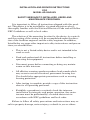
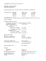
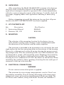
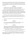
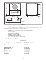
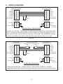
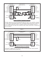
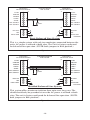
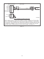
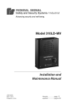
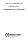
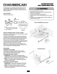
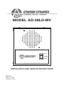
MODEL AD-28LD-MV
CALL
LISTEN
UNIVERSITY PARK, IL USA
TALK
WARNING: DISCONNECT POWER BEFORE REMOVING COVER
INSTALLATION AND SERVICE INSTRUCTIONS
2562445A
REV. A 1108
Printed in U.S.A.
INSTALLATION AND SERVICE INSTRUCTIONS
FOR
MODEL AD-28LD-MV
SAFETY MESSAGE TO INSTALLERS, USERS AND
MAINTENANCE PERSONNEL
It is important to follow all instructions shipped with this product. This device is to be installed by a trained electrician who is
thoroughly familiar with the National Electrical Code and will follow
NEC Guidelines as well as local codes.
The selection of the mounting location for the device, its controls
and the routing of the wiring is to be accomplished under the direction of the facilities engineer and the safety engineer. In addition,
listed below are some other important safety instructions and precautions you should follow:
• This is not a Listed safety device and is not intended to be
used as such.
• Read and understand all instructions before installing or
operating this equipment.
• Disconnect power before connecting or doing any maintenance on this intercom.
• All effective warning speakers produce loud sounds which
may cause in certain situations, permanent hearing loss.
You should take appropriate precautions such as wearing
hearing protection.
• After testing is complete, provide a copy of this instruction
sheet to all operating personnel.
• Establish a procedure to routinely check the intercom
installation for integrity and proper operation. Any maintenance must be performed by a trained electrician in
accordance with NEC guidelines and local codes.
Failure to follow all safety precautions and instructions may result in property damage, serious injury, or death to you or others.
-2-
A. GENERAL FEATURES.
The AD-28LD-MV intercom is a 2-way communications device
designed for light duty industrial applications. Nominal operating
voltages include 120/240 Vac, 50/60 Hz and 24 Vdc. Voltage changes
for the 120/240VAC are internally switch selectable and the AC line
is fused with a 1/2 amp 250 volt type GMC fuse. The unit also offers
internally selectable balanced or unbalanced line operation, transformer isolated audio inputs and internally selectable Master or Slave
mode configurations. A call button with remote call dry contacts is
also factory supplied in the unit. The AD-28LD-MV has a Type 1 enclosure and is a UL Listed signal appliance.
MASTER MODE:
Each intercom can be configured as a Master unit (Push-to-Talk)
or a Slave unit (Push-to-Listen) by changing the MAS/SLA jumper
(J3) on the printed circuit board (see figure 1). The intercom comes
from the factory set in the Master (MAS) mode.
In the Master mode the intercom acts as an amplifier, constantly
broadcasting over its speaker any signal that it receives on the signal
lines. Holding down the Listen/Talk switch changes the unit from a
speaker to a microphone (see figure 2). The intercom will now transmit over the signal lines to additional intercom(s) also set in the
TO SPEAKER
Q1
IC1
R4
T1
C3
H1
J1 S
P
K
R
C4
+
CR1
C1
R1
C12
R5
C11
R6
R7
R2
R8
J6
R9
R10
R11
C
H
R12
R13
S
W
I
T
J3
T2
>SLA
>MAS
C13
C2
T3
SW1
120VAC
1/2A
250V
GMC-1/2
F1
>BAL
>UNB
J4 J5 R17
CR4
CR5
CR6
CR7
R18
1
R19
K2
240VAC
C15
C16
IC2
REPLACE WITH SAME
TYPE FUSE ONLY
TO SWITCH
R20
R21
R22
C14
Q2
C9
K1
CR2
FUSE
C10
R3
C5
H2
120VAC/240VAC
SWITCH
C6
C7
C8
R23
R24
R25
R26
C17
C18
C19
C20
MASTER/SLAVE
JUMPER
R27
R28
IC3
R29
R30
R31
R14
R15
R16
CR3
BAL/UNBAL
JUMPER(2)
R32
R33
CR8
Q3
C21
J7
C22
R34
V
O
L
VOLUME
CONTROL
24VDC
IN/OUT
GROUND
CLASS II WIRING
REMOTE
CONTROL
REMOTE +
SPEAKER
CM
-
EXT CALL
CONTACT
J2
2001290 A
CLASS I WIRING
290A3076
Figure 1.
-3-
CALL
LISTEN
UNIVERSITY PARK, IL USA
TALK
WARNING: DISCONNECT POWER BEFORE REMOVING COVER
290A3077B
Figure 2.
master mode. When the switch is released it will default back to the
Listen or Speaker mode, allowing the user to receive any messages
transmitted back to it. The output amplifier offers full short circuit
protection and over heat protection.
SLAVE MODE:
Some applications may require that the intercom constantly
transmit (i.e., act as a microphone) as opposed to constantly receive
(i.e., act as a speaker). To accomplish this the intercom must be
switched into the Slave (Push-to-Listen) mode.
WARNING
Disconnect power to the intercom before any installation,
maintenance, or configuration changes are performed.
Move the J3 jumper block on the P.C. board from the MAS to SLA
position (see figure 1). This can be done using long nose pliers, pulling the block off the “MAS” and center position and placing it on the
“SLA” and center position.
When hooked to a Master unit it may be necessary to override
the Slave unit in order for the Master unit to be able to transmit. The
remote control and ground lines must be connected between the Master and the Slave unit. Paragraph G. WIRING DIAGRAMS contains
wiring diagrams of typical intercom configurations.
-4-
REMOTE CONTROL:
Remote control is used to change the operation mode of a remote
intercom from listen to talk or from talk to listen upon activation of
a local intercom. The wiring diagram section illustrates Master/Slave
Installation and Using Foot Switches Diagrams. (See figures 5 and 6.)
Normally open foot switches can also be connected to the Remote
Control line and ground in order to allow “hands free” operation of the
listen/talk functions.
CALL BUTTON AND CALL DRY CONTACTS TO EXTERNAL DEVICE:
Depressing the call button sends a 1 kHz tone onto the signal
lines. All units listening to the line will then broadcast this signal as
a call. Depressing the call button also closes a normally open dry contact rated at 0.4 amps @ 125 Vac or 1.25 amps @ 24 Vdc. This contact
can be used to trigger a remote sounder or light in order to accent the
call feature. The wiring diagram illustrates how an external light or
horn can be wired in to augment the call tone. (See figure 7.)
CAUTION
The call signal is substantially louder than normal voice messages being carried on the line. Do not depress the call switch
while carrying on a conversation with someone on the system.
This will subject the listener to very loud sound levels.
24 Vdc:
The AD-28LD-MV is capable of sending DC power to another unit
that is mounted in a remote location without local power. 24 Vdc is
available from positions 6 and 7 of terminal block J7. It can be run
along with the signal lines to an intercom in a remote location. Only
one unit should share the power supply of another unit in any installation. Figure 8 in the wiring diagrams section shows how two intercoms can be hooked up if no remote power is available.
CAUTION
If an intercom is intended to be run off of a separate 24 Vdc
supply, the output must be limited to 24 Vdc, 760 mA output.
-5-
J7
24VDC IN/OUT
GROUND
REMOTE CONTROL
+
J2
REMOTE SPEAKER
COMMON
PHASE
-
EXT CALL
CONTACT
GROUND
CLASS I WIRING
CLASS II WIRING
290A3078
Figure 3.
ISOLATED BALANCED/UNBALANCED LINES:
The audio signals are transmitted over a wire pair using balanced
line technology. This means each wire carries a signal that is opposite
in polarity of the other. At the input of the intercom is an isolated
balanced line transformer. This transformer subtracts the two signals
from each other providing an output free of noise generated onto the
wires by some other noise source such as a motor or light fixture near
the wires.
The isolation provided by the transformer means that the grounds
of the units are not connected by the audio lines. Therefore, ground
loops and other problems caused by non-isolated systems are avoided.
The polarity of the audio lines between the + and - signal terminals
need not be maintained.
A shielded cable can be used in installations where extreme
problems from interference are suspected. The shield should always
be connected to the ground of only one of the intercoms. Connecting
the shield to ground at both ends will cause ground currents to travel
through the shield which could cause hum in the system.
There are several diagrams in the back of the manual to aid in
wiring intercoms together. The wiring diagram section illustrates balanced and unbalanced line interconnection along with how a shielded
audio cable can be used. (See figures 5 through 12.) It also illustrates
-6-
multiple intercom interconnections.
MODEL AD-28LD-MV
SPECIFICATIONS
Operating Voltage 24 Vdc, 120Vac and 240 Vac 50/60 Hz
Current Draw
Voltage
24 Vdc
120 Vac
240Vac
Operating
120 mA
80 mA
40 mA
Standby
60 mA
60 mA
30 mA
CAUTION: The 24Vdc input must be limited to 760 mA out if run
from a supply.
Amplifier Specifications
Frequency Response (–6 dB)150 Hz to 12 kHz
Input Impedance
3400 ohms
Max. Output Voltage
Sine Wave:
Balanced Output 15 Vrms
Unbalanced Output 7.5 Vrms
Square Wave:
Balanced Output 19 Vrms
Unbalanced Output 9.5 Vrms
Speaker Rating
Speaker Impedance
Temperature Range
2 watts
8 ohm
−31 °F to +150° F
(–35 °C to +66 °C)
Fuse Type GMC-1/2
Call Switch Contact Rating
1/2 A, 250 V
400 mA @ 125 Vac
1.25 A @ 24 Vdc
Agency Approvals
UL, Type 1
Weight
Shipping Net Housing Dimensions
Conduit Entrances
Housing Material
Color 3 lb, 9 oz
3 lb, 2 oz
6.87" W x 8.00" H x 3.05" D
Dual 1/2"-3/4" Knockouts
Aluminum
Black
-7-
B. UNPACKING.
After unpacking the Model AD-28LD-MV, examine it for damage
that may have occurred in transit. If the equipment has been damaged, do not attempt to install or operate it, file a claim immediately
with the carrier stating the extent of the damage. Carefully check all
envelopes, shipping labels and tags before removing or destroying
them.
Before attempting to install the intercom, be sure that all parts
listed in the KIT CONTENTS LIST have been supplied.
C. KIT CONTENTS LIST.
Qty.
Description Part Number
1 Instruction Manual
1 Resistor, 1 K, 1 W
2562445
K101216
D. MOUNTING.
CAUTION
The selection of the mounting location for the device, its controls and the routing of the wiring is to be accomplished under
the direction of the facilities and the safety engineer.
The intercom is intended to be mounted on any relatively flat and
rigid surface by the four mounting holes in the interior of the housing.
Figure 4 is a dimensional outline drawing showing the proper mounting configuration. The four mounting holes are 0.202 in diameter and
are designed to accept a #10 mounting screw. Hardware for mounting
the intercom to the surface is left up to the installer. The intercom
housing has two combination 1/2"-3/4" knockouts in the bottom. When
installing the conduit to these openings, choosing the size and type of
connector is left up to the installer.
E. ELECTRICAL CONNECTIONS.
WARNING
Do not connect wires when power is applied.
The intercom has two wiring compartments, one for Class I wiring and the second for Class II wiring. All wiring to the intercom is
terminated at two pc board mounted terminal blocks provided. The
AC Phase and Common, along with Earth Ground, are landed in a
-8-
three-position terminal block (J2) in the Class I wiring compartment.
The signal lines, remote control lines, remote power, and call dry contacts are landed in a seven-position terminal block (J7) in the Class II
wiring compartment. The two wiring sections are isolated by a fishpaper barrier.
WARNING
Disconnect power to the intercom before any installation,
maintenance, or configuration changes are performed.
There are three jumpers shown on the PC board in Figure 7 that
may need to be moved depending on the desired operation of the
intercom. J4 and J5 are for operating the intercom in either a balanced signal line or unbalanced signal line configuration. These must
be moved together as a pair. They are factory set in the balanced line
position. J3 is for configuring the intercom as either a master or slave
device. The intercom is factory set in the master position.
There is a switch on the board, in the Class I wiring compartment, to configure the operation of the board from 120 Vac to 240 Vac.
The switch is factory set for the intercom to operate on 120 Vac (see
figure 3).
See figures 5 through 12 for typical intercom configurations.
F. SERVICE.
CAUTION
Any maintenance must be performed by a trained electrician
in accordance with NEC guidelines and local codes.
1. General.
CAUTION
The call signal is substantially louder than normal voice messages being carried on the line. Do not depress the call switch
while carrying on a conversation with someone on the system.
This will subject the listener to very loud sound levels.
Federal Signal will service your equipment or provide technical assistance with any problems that cannot be handled locally.
Any units returned to Federal Signal for service, inspection, or
repair must be accompanied by a Return Material Authorization.
This R.M.A can be obtained from the local Distributor or Manufacturer’s Representative.
-9-
8.00
7.125
CALL
LISTEN
UNIVERSITY PARK, IL USA
TALK
WARNING: DISCONNECT POWER BEFORE REMOVING COVER
BACK
FRONT
CLASS I WIRE
ENTRY
3.50
5.50
4 x .202
COMBINATION 1/2"-3/4" KNOCK-OUT
3.05
CLASS II WIRE ENTRY
1.40
BOTTOM
6.87
290A3079B
Figure 4.
At this time a brief explanation of the service requested or the
nature of the malfunction, should be given.
Address all communications and shipments to:
Service Dept.
Atkinson Dynamics
Federal Signal Corp.
2645 Federal Signal Dr.
University Park, IL 60466-3195
2. Replacement Parts.
WARNING
Replace fuse with GMC-1/2 only. DO NOT substitute.
Description
Part Number
Resistor, 1 K, 1 W
Fuse, GMC-1/2
Mini-jumpers PCBA Switch Speaker K101216
K148A155
K139A209
K2001290
K122283
K132141
-10-
G. WIRING DIAGRAMS.
INTERCOM I
AD-28LD-MV MASTER
MASTER/SLAVE INSTALLATION
INTERCOM II
AD-28LD-MV SLAVE
J7
J7
24 VDC
7
7
24 VDC
GROUND
6
6
GROUND
REMOTE
5
5
REMOTE
AUDIO +
4
4
AUDIO +
AUDIO -
3
3
AUDIO -
DRY CONTACT
2
2
DRY CONTACT
DRY CONTACT
1
1
DRY CONTACT
3
NEUTRAL
2
HOT
1
EARTH GND.
1K
1 WATT
J2
NEUTRAL
3
HOT
2
EARTH GND.
1
J2
AC
AC
290A3080B
Master Slave Installation
In this installation, the Master is constantly broadcasting audio from the
Slave. Pushing the listen/talk switch on either unit forces the Slave into
the listen mode and the Master into the talk mode. The MAS/SLA jumper
must be placed in the SLA mode for this operation on the slave unit.
Figure 5.
INTERCOM I
AD-28LD-MV MASTER
J7
USING FOOT SWITCHES
FOOT SWITCH
N.O.
FOOT SWITCH
N.O.
INTERCOM II
AD-28LD-MV SLAVE
J7
24 VDC
7
7
24 VDC
GROUND
6
6
GROUND
REMOTE
5
5
REMOTE
AUDIO +
4
4
AUDIO +
AUDIO -
3
3
AUDIO -
DRY CONTACT
2
2
DRY CONTACT
DRY CONTACT
1
1
DRY CONTACT
3
NEUTRAL
2
HOT
1
EARTH GND.
1K
1 WATT
J2
NEUTRAL
3
HOT
2
EARTH GND.
1
J2
AC
AC
290A3081B
Using Foot Switches
Using normally open, simple contact closure foot switches (customer
supplied) allows for total hands free operation of the listen/talk functions.
Figure 6.
-11-
INTERCOM I
AD-28LD-MV MASTER
24 VDC
7
GROUND
6
REMOTE
J7
USING CALL DRY
CONTACTS WITH AC
INTERCOM II
AD-28LD-MV SLAVE
J7
1K
1 WATT
7
24 VDC
6
GROUND
5
5
REMOTE
AUDIO +
4
4
AUDIO +
AUDIO -
3
3
AUDIO -
DRY CONTACT
2
2
DRY CONTACT
DRY CONTACT
1
1
DRY CONTACT
POWER
J2
NEUTRAL
3
HOT
2
EARTH GND.
1
POWER
AC
AC
J2
3
NEUTRAL
2
HOT
1
EARTH GND.
290A3082B
Using Call Dry Contacts with AC
The dry contacts can be used to switch devices such as an auxiliary sound
or light when call is depressed. The maximum ratings for the dry contacts
are .4 amps @ 125VAC and 1.25 amps @ 24VDC. This method assures a
call is received even when the volume on one of the intercoms is turned all
the way down.
Figure 7.
INTERCOM I
AD-28LD-MV MASTER
J7
24 VDC
7
NO REMOTE POWER
AVAILABLE
INTERCOM II
AD-28LD-MV SLAVE
J7
7
24 VDC
GROUND
6
6
GROUND
REMOTE
5
5
REMOTE
AUDIO +
4
4
AUDIO +
AUDIO -
3
3
AUDIO -
DRY CONTACT
2
2
DRY CONTACT
DRY CONTACT
1
1
DRY CONTACT
3
NEUTRAL
2
HOT
1
EARTH GND.
1K
1 WATT
J2
NEUTRAL
3
HOT
2
EARTH GND.
1
J2
AC
290A3083B
No Remote Power Available
Intercom I supplies the DC power to the second intercom. Earth ground
must be wired on the second unit.
Figure 8.
-12-
INTERCOM I
AD-28LD-MV MASTER
BASIC BALANCED
LINE SYSTEM
INTERCOM II
AD-28LD-MV SLAVE
J7
J7
24 VDC
7
7
24 VDC
GROUND
6
6
GROUND
REMOTE
5
5
REMOTE
AUDIO +
4
4
AUDIO +
AUDIO -
3
3
AUDIO -
DRY CONTACT
2
2
DRY CONTACT
DRY CONTACT
1
1
DRY CONTACT
3
NEUTRAL
2
HOT
1
EARTH GND.
1K
1 WATT
J2
NEUTRAL
3
HOT
2
EARTH GND.
1
J2
AC
AC
290A3084B
Basic Balanced Line System
This is a simple system with only two conductors connected between the
units. AC power is utilized at both sites. The Unit is factory configured
for balanced line operation. (NOTE: both jumpers in BAL position.)
Figure 9.
INTERCOM I
AD-28LD-MV MASTER
J7
24 VDC
7
SHIELDED BALANCED
LINE SYSTEM
INTERCOM II
AD-28LD-MV SLAVE
J7
7
24 VDC
GROUND
6
6
GROUND
REMOTE
5
5
REMOTE
AUDIO +
4
4
AUDIO +
AUDIO -
3
3
AUDIO -
DRY CONTACT
2
2
DRY CONTACT
DRY CONTACT
1
1
DRY CONTACT
3
NEUTRAL
2
HOT
1
EARTH GND.
1K
1 WATT
J2
NEUTRAL
3
HOT
2
EARTH GND.
1
J2
AC
AC
290A3085B
Shielded Balanced Line System
This system offers maximum isolation from noise over long runs. The
shield should only be grounded at one side. AC power is utilized at both
sites. The unit is factory configured for balanced line operation. (NOTE:
both jumpers in BAL position.)
Figure 10.
-13-
INTERCOM I
AD-28LD-MV MASTER
24 VDC
7
GROUND
6
REMOTE
5
AUDIO +
4
AUDIO -
3
DRY CONTACT
2
DRY CONTACT
1
BASIC UNBALANCED
LINE SYSTEM
J7
AC
1K
1 WATT
AUDIO
CABLE
GROUND
J2
NEUTRAL
3
HOT
2
EARTH GND.
1
AC
290A3086B
Basic Unbalanced Line System
This configuration is used when hooking to other products on the market.
This system does not offer the same level of noise isolation as a balanced
line system and should only be used when hooking to existing devices. The
neighboring jumpers on the circuit board must be changed from the BAL
position to the UNB position for these installations (see figure 1).
Figure 11.
-14-
INTERCOM I
AD-28LD-MV MASTER
24 VDC
7
GROUND
6
REMOTE
5
AUDIO +
MULTIPLE INTERCOMS
INTERCOM 2
AD-28LD-MV SLAVE
J7
J7
7
24 VDC
6
GROUND
5
REMOTE
4
4
AUDIO +
AUDIO -
3
3
AUDIO -
DRY CONTACT
2
2
DRY CONTACT
DRY CONTACT
1
1
DRY CONTACT
NEUTRAL
3
3
NEUTRAL
HOT
2
2
HOT
EARTH GND.
1
1
EARTH GND.
INTERCOM 3
310-MV MASTER
INTERCOM 4
310X-MV SLAVE
1K
1 WATT
J2
J2
AC
AC
DRY CONTACT
10
10
DRY CONTACT
DRY CONTACT
9
9
DRY CONTACT
AUDIO -
8
8
AUDIO -
AUDIO +
7
7
AUDIO +
REMOTE
6
6
REMOTE
GROUND
5
5
GROUND
24 VDC
4
4
24 VDC
NEUTRAL
3
3
NEUTRAL
HOT
2
2
HOT
EARTH GND.
1
1
EARTH GND.
AC
AC
Multiple Intercoms
290A3087B
Multiple intercoms can be tied to one line. Depressing talk on any unit
will broadcast audio over all other units. (NOTE: only one line resistor
needs to be installed on the line for any installation.)
Figure 12.
-15-