1
Agilent
Introduction to Application
Development with the Agilent PNA
Series of Network Analyzers
Product Note
Table of Contents
1.0 Introduction ..............................................................................................................................3
NOTE: Procedures apply to models E8356A, E8357A, E8358A of the PNA Series VNA’s
2.0 Basic Administration ........................................................................................................3
2.1 Administrator grants log on access to the PNA for specific users ...................3
2.2 Sharing a drive between PC and PNA ..........................................................................4
3.0 Software Installation ........................................................................................................5
3.1 Set-up for software installation over LAN .....................................................................5
3.2 Set-up for software installation from external USB CD Drive ..............................6
3.3 Software installation .........................................................................................................6
4.0 Configuring COM/DCOM.................................................................................................7
4.1 Procedure ...............................................................................................................................7
4.1.1 Configure the PNA Series network analyzer to provide COM/DCOM
access to the PNA application for the user ......................................................................7
4.1.2 Configure the user’s PC for DCOM access to the PNA application .................................9
5.0 Introduction to Application Examples
...............................................................10
5.1 Application examples .........................................................................................................10
5.1.1 Microsoft® Visual Basic® Example .................................................................................10
5.1.1.1 Application Configuration ........................................................................................10
5.1.1.2 Application Code .....................................................................................................11
5.1.1.3 Application Output ...................................................................................................11
5.1.2 Microsoft Visual Basic Script Example ...........................................................................12
5.1.2.1 Application Configuration ........................................................................................12
5.1.2.2 Application Code .....................................................................................................12
5.1.2.3 Application Output ...................................................................................................12
5.1.3 Microsoft Word® Example ................................................................................................13
5.1.3.1 Application Configuration ........................................................................................13
5.1.3.2 Application Code .....................................................................................................13
5.1.3.3 Application Output ...................................................................................................14
5.1.4 Microsoft Excel® Example ................................................................................................14
5.1.4.1 Application Configuration ........................................................................................14
5.1.4.2 Application Code .....................................................................................................14
5.1.4.3 Application Output ...................................................................................................15
5.1.5 Microsoft Visual® C++ Example .......................................................................................15
5.1.5.1 Application Configuration ........................................................................................15
5.1.5.2 Application Code .....................................................................................................15
5.1.5.3 Application Output ...................................................................................................16
5.1.6 Agilent VEE Example .........................................................................................................16
5.1.6.1 Application Configuration ........................................................................................16
5.1.6.2 Application Code .....................................................................................................17
5.1.6.3 Application Output ...................................................................................................17
5.1.7 National Instruments™ LabVIEW Example .......................................................................17
5.1.7.1 Application Configuration ........................................................................................17
5.1.7.2 Application Code .....................................................................................................17
5.1.7.3 Application Output ...................................................................................................17
Appendix A: Quick Guide ................................................................................................................18
2
1.0 Introduction
2.0 Basic Administration
This product note provides a step-by-step guide to system administration, software installation, and
COM/DCOM setup on a PNA Series network analyzer
(E8356A, E8357A, and E8358A). After reading this
product note, you will be able to:
To obtain access to the PNA Series network analyzer for
COM/DCOM, a user must be registered on the network
analyzer. (NOTE: This is the same procedure a system
administrator must use to grant multiple users permission to log on to the network analyzer and maintain their
user profile.)
1) Add user profiles to your network analyzer
2) Share drives between your network analyzer and
PC running Windows® 95, 98, NT 4.0 or higher
3) Load software on your network analyzer over the
LAN or from an external CD drive
4) Configure your network analyzer and PC for
COM/DCOM communications
Additionally, this product note provides a simple programming example in seven common languages
(Microsoft® Visual Basic, Visual Basic Script, Word, and
Excel, Agilent VEE, Visual C++, and National
Instruments™ LabVIEW) that demonstrate the differences between development platforms.
The procedures listed in this product note are valid for a
PC with Windows 95, 98, NT 4.0 or higher operating systems. This product note was developed on a PC with
Windows NT version 4.0 with service pack 5. The PNA
Series network analyzer’s operating system was Windows
2000 Professional. However, the steps will be similar for
Windows 95 and 98.
3
This section also contains the steps to share drives
between the network analyzer and a PC. Any drive can
be shared between the network analyzer and PC including a CD drive for software installation over the LAN
(described in further detail in step 3.1). To enable
COM/DCOM communications to and from the PC and
network analyzer, share the network analyzer’s C drive
with your PC.
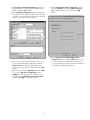
2.1 A system administrator grants log on
access to the PNA Series network
analyzer for specific users:
From the PNA Series network analyzer:
1) The system administrator must log on to the PNA
Series analyzer using the administrator username
and password.
2) Once logged on to the network analyzer, right-click
on My Computer. Clicking on Manage will launch
the Computer Management utility.
3) In the Computer Management window, expand
Local Users and Groups. Left-click on Users.
The list of Users will appear in the right half of the
window. Right-click on Users, and click on New
User in the pop-up menu. This launches the New
User window.
4) In the User name input box, enter the user name
which the user logs in to his/her PC with. The Full
name and Description boxes are optional and so
can remain empty. In the Password input box,
enter the password, which the user logs in to
his/her PC with, and enter the same password for
Confirm password. The User must change
password at next log on check box is checked
by default. In most cases, it is recommended to
check Password never expires. Click the Create
button to finish setting up the user.
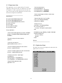
2.2 Sharing drives between a PC and PNA
Both the PC and network analyzer must be connected to
the LAN.
Determine the Full Computer Name of the device’s
drive you want to share. To access the network analyzer
from your PC, find the Full Computer Name of the
network analyzer. To access your PC from the network
analyzer, locate the Full Computer Name of your PC.
The following are steps to find this information from
either your PC or network analyzer:
From the PNA Series network analyzer:
1) Click the Windows Start button, select Settings,
and Control Panel.
2) In the Control Panel window, double click the
System icon.
3) From the System Properties window, click the
Network Identification tab. Record the
analyzer’s Full Computer Name:______________.
4) Click OK to close the System Properties window.
5) Close the Control Panel window.
From your PC:
1) Single right click on the Network Neighborhood
desktop icon. Select Properties. Record the
Computer Name_______________. Close the
dialog box.
5) The New User window remains active, but the
input boxes are cleared and the check boxes
returned to their default settings. Click the Close
button to close the New User window. Notice that
the user has been added to the list in the Computer Management window. Close the Computer
Management window. The user now has access to
the PNA network analyzer.
4
Next, share drives between the network analyzer and
your PC. This procedure is required to configure
COM/DCOM access between your PC and PNA Series
network analyzer. The following steps demonstrate how
to share the PNA’s C drive with your PC. You can also
access your PC’s C drive from the analyzer. To do this,
reverse Analyzer and PC throughout the following procedure.
From the PNA network analyzer:
1) Double click on the My Computer desktop icon to
determine if the C drive is “shared”.
2) Single right click the C drive. Select Sharing.
3) Under the Sharing tab, select the Share as…
radio button.
4) Type a share name (or use the default C$). Record
the share name here_______________.
5) Close the dialog box.
From your PC:
1) Map the network analyzer’s drive to the PC.
Launch Windows Explorer to begin this
procedure.
2) On the main menu bar, click Tools. From the
menu, click Map Network Drive. Your PC will
choose the next available drive letter. It is also
possible to assign other available drives. Record
this drive letter:_______________.
3) From the Map Network Drive window, click
the Path box (this is the Folder box on the net
work analyzer). Type (or select if available) the
path (\\computername\sharename). The computer
name and the share name were recorded in the
preceding steps. To connect to the shared drive
automatically each time you log on, check
Reconnect at Logon.
NOTE:
For PC’s running Windows NT 4.0 or higher:
If you are logged onto the analyzer using the
same logon as your PC, it is not necessary to
enter “Connect As”. However, if you want to
connect under a different user name, type the
name in Connect As (to do this on the network
analyzer, select “Connect using a different user
name”). If the user name is in a different
domain, use the format: domain\username.
If your PC is running Windows 95 or 98:
It is necessary to connect to the analyzer using
the same login and password as those used to
log on to your PC.Click OK to close the Map
Network Drive window.
4) The analyzer’s C drive should be visible on your
PC’s Windows Explorer as the drive letter
assigned in step 3.
5
3.0 Software Installation
3.1 Set-up for software installation over LAN
If you do not have access to a USB external CD drive, it is
possible to map your PC’s CD drive to the PNA Series analyzer. Both your PC and network analyzer must be connected to the LAN. The software can then be installed
from your PC’s CD drive.
From your PC:
1) Place the software CD-ROM in the CD drive.
2) Single right click on the Network Neighborhood
desktop icon. Select Properties. Record the
Computer Name here:______________. Close the
dialog box.
3) Make sure the CD drive has been “shared” by
double clicking on the My Computer desktop icon.
Single right click the CD drive. Select Sharing.
Under the Sharing tab, select the Share as…
radio button. Record the share name
here:_______________. Close this dialog box.
From your PNA Series Network Analyzer:
4) Next, map your PC’s CD drive to the network
analyzer. Launch Windows® Explorer to begin
this procedure.
5) On the main menu bar, click Tools. From the
menu, click Map Network Drive. The network
analyzer will choose the next available drive letter.
It is also possible to assign other available drives.
Record this drive letter:_______________.
6) From the Map Network Drive window, click the
Folder box. Type (or select if available) the path
(\\computername\sharename). You learned the
computer name in step 2 and the share name in
step 3. NOTE: If you are logged onto the analyzer
using the same logon as your PC, it is not necessary
to enter “Connect Using a Different User Name”.
However, if you prefer to connect under a different
user name, click the hyperlink “different user
name” and type the user name and password. If the
user name is in a different domain, use the format:
domain\username.
3.2 Set-up for software installation from
external USB CD Drive
This procedure has been verified for the HP CDR-Writer
Plus 8200 series CD drive. The following procedure has
not been verified with other USB CD drives.
From your PNA Series Network Analyzer:
1) Exit all applications, including the network
analyzer application.
2) Plug your CD drive’s USB cable into a USB
port located on the network analyzer.
3) Turn on your external CD drive.
4) Wait until Windows recognizes the CD drive.
The Add/Remove Hardware Wizard will
automatically launch.
5) Follow the steps to install the drivers for your CD
drive.
6) You may have to re-start the network analyzer to
finish the installment of the drivers, which will
allow read/write permission from/to the external
CD drive. Proceed to the Software Installation
Section 3.3.
3.3 Software installation
This procedure is general, and has been verified on
Microsoft Visual Basic 6.0, Visual C++ 6.0, and Office
2000, National Instruments™ LabVIEW, and Agilent VEE
6.0. If you have mapped your PC’s CD drive, perform the
following procedure from your PC. If you have an external USB CD drive set up, perform the following procedure from your network analyzer.
7) To connect to the shared drive automatically each
time you log on, check Reconnect at Logon.
8) Click Finish to close the Map Network Drive
window.
9) The PC’s CD drive will now be visible on the
network analyzer’s Windows Explorer as the
drive letter you used in step 5.
10) A window will popup with the contents of the
CD drive on the PC.
11) Proceed to the Software Installation Section 3.3.
6
1) Insert the software CD into your CD drive.
2) If installation does not immediately start, double
click My Computer. Then, double click the CD.
Run the setup application as outlined in the
software’s documentation. Select the network
analyzer’s drive as the destination for the files to be
installed.
4.0 Configuring COM/DCOM
4.1 Procedure
When configuring COM/DCOM, the first issue to consider
in this topic is Windows® NT/Windows® 2000 Domains
versus Workgroups.
4.1.1 Configure the PNA Series network analyzer to
provide COM/DCOM access to the PNA application
for the user
• A domain is a typically large organizational group
of computers that network administrators maintain
and control which machines have membership.
• A workgroup, on the other hand, does not require
a network administrator to create it or control
membership. It just requires a person who is an
administrator of the PNA Series network analyzer
to declare the workgroup name and to declare the
analyzer a member of the workgroup. The PNA
Series analyzers are shipped from Agilent
configured as members of a workgroup named
WORKGROUP.
The analyzer cannot be configured as both a domain
member and workgroup member; it must be one or the
other. By default, PNA Series analyzers are shipped from
Agilent such that everyone has permission to launch
and access the PNA Series application via COM/DCOM.
The term everyone refers to a different range of users
depending upon which type of group (domain or workgroup) the network analyzer is a member of. For a workgroup, Everyone includes only those users who have
been given logon accounts on the analyzer. For a
domain, Everyone includes that same group of users,
and also includes those people who have permissions to
logon to the domain but perhaps do not have a logon
account on the analyzer. In general, once a PNA Series
analyzer has joined a domain with permission from a
network administrator, it tends to make network connections to the network analyzer easier for those people
who have domain logon accounts. For example, with the
Agilent default setting of everyone having permission to
launch/access the PNA Series application, anyone who is
logged into the domain from their PC will then automatically have the necessary permissions to connect to the
analyzer using DCOM. Recall that when the network
analyzer is a member of a workgroup instead of a
domain, only those people who have logon accounts on
the analyzer can connect using DCOM from a PC.
7
From the PNA Series Network Analyzer:
NOTE: The following steps need to be performed when
it is desired to give specific users (not Everyone)
COM/DCOM permissions.
Remember, both your PC and the analyzer must be connected via the LAN. Additionally, the network analyzer’s
C drive must be mapped to your PC as shown in section
2.2.
1) Click the Windows Start button, select Run, type
dcomcnfg into the input box, and click OK.
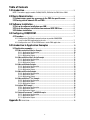
2) The Distributed COM Configuration
Properties window should now be displayed. Click
on Agilent PNA Series in the Applications list,
then click the Properties button.
3) In the Agilent PNA Series Properties window,
click the Location tab. The Run application on
this computer checkbox should be checked.
4) Click the Security tab. Click the Use custom
access permissions and Use custom launch
permissions radio buttons to select those options.
Click the Edit... button next to Use custom
access permissions.
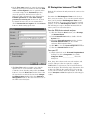
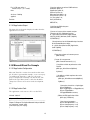
5) The Registry Value Permissions dialog box for
Registry Value: Access Permission should now be
visible. Click the Add... Button.
6) The Add Users and Groups window should now
be visible. The list of names visible are the Groups
of people given permission by the system administrator to access the network analyzer.
9) In the Agilent PNA Series Properties window
click the Identity tab. Ensure The interactive
user option button is selected. Click the OK
button.
10) In the Distributed COM Configuration
Properties window click the OK button to close
it. The PNA is now configured to give the user
access permission as well as launch permission for
the Agilent PNA Series application.
7) Select one or more of these groups to give access
to the Agilent PNA Series application. Click the
Show Users button. Now scroll down the list,
select the user you wish to add and click the Add
button.
8) The user is now in the Add Names list. Click OK
to close the Add Users and Groups window.
NOTE: The user is now listed as having access
permission in the Registry Value Permissions
window. Click OK to close that window.
8
Problems?
4.1.2 Configure the user’s PC for DCOM access to
the PNA application
From your PC:
1. Using your PC's Windows Explorer, find the analyzer’s
mapped local hard drive and click the Program
Files/Agilent/Network Analyzer/Automation
folder.
When the network analyzer application is installed on
the instrument, the application and all the objects it
serves are registered on that machine. The instrument
should be ready to perform as a remote server.
If the analyzer is not working properly, try re-registering
the application and associated libraries through the following steps:
NOTE: The following must be done in the listed order
From the PNA network analyzer:
Find E835x.exe in C:\Program Files\Agilent\Network
Analyzer
1. Select and right-click 835x.exe
2. Select Register COM Server to register the
application.
3. Select and right-click 835xps.DLL
4. Select Register COM Server
DCOM settings
5. Click Start
6. Select RUN and type dcomcnfg
7. From the application list, find and select 835X
8. Click Properties
9. Select the Identity tab.
10. Select INTERACTIVE USER
11. Select the Security tab
12. Set permissions and access to CUSTOM
13. Edit the lists to specify the remote user
2. Double-click Automation.vbs and follow the
instructions. After this procedure is completed, a
Network Analyzer Setup icon is setup on your PC
desktop.
NOTE: Your PC’s operating system may require a
Visual Basic Scripting engine to run the .vbs file. To
download a free copy of a Visual Basic Scripting
engine, visit Microsoft’s® web site.
9
5.0 Introduction to Application
Examples
5.1 Application examples
The analyzer’s support for DCOM (Distributed
Component Object Model) over the LAN provides control of the network analyzer using a variety of platforms.
DCOM acts as an interface to the analyzer for external
applications. With DCOM, the programmer can develop
an application on an external computer. During development, the application will interface to the analyzer over
the LAN through the DCOM interface. Once the developer has finished the application, it can be distributed to
the analyzer. After, it has been distributed to the analyzer, the application will interface with the analyzer using
COM.
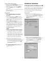
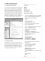
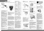
5.1.1.1 Application Configuration
5.1.1 Microsoft Visual Basic Example
The type library for the PNA should be referenced in the
Visual Basic development environment. The following
figure illustrates the reference.
The example applications in this product note were
developed in a number of different programming languages to show the differences between development
platforms. The application was first developed on a PC
and then transferred to the analyzer once development
was complete.
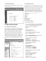
The table below outlines the setup parameters that the
applications will use to configure the PNA network analyzer for a measurement.
Parameter
Value
Start Frequency
1 GHz
Stop Frequency
2 GHz
Number of Points
11
Measurement
S11
Data Storage Area
Uncorrected (Raw Data)
Data Format
Log Magnitude
Trigger Mode
Single
The device tested was a 50 ohm standard load on port 1
of the analyzer
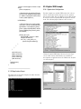
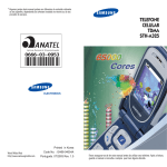
Using the Visual Basic Object Browser the developer can
see what classes and methods are available for development of applications for the analyzer (see figure below).
Download the example programs and obtain more
detailed information for each development environment
from http://agilent.com/find/pna_applications
The development environment should reference the
type library associated with the PNA Series. For example, in Visual Basic, add the Agilent PNA 835x type
library as a reference. This will allow the program to
“see” the various classes and methods for use with the
PNA Series network analyzer during development (see
the individual programming examples for more information).
10
5.1.1.2 Application Code
The application code is contained below. To run the
application, first generate the executable file. Once this
is complete, it can be copied and executed on the analyzer or run on the PC. The application can also be run
from the development environment.
' Set channel parameters
chan.NumberOfPoints = 11
chan.StartFrequency = (1000000000#)
chan.StopFrequency = (2000000000#)
' Send a manual trigger to initiate a single sweep
chan.Single True
Option Explicit
' Store the data in the "result" variable
result = meas.GetData(naRawData,
naDataFormat_LogMag)
Dim app As AgilentPNA835x.Application
Dim chan As AgilentPNA835x.Channel
Dim meas As AgilentPNA835x.Measurement
Dim result As Variant
Dim i As Integer
Dim num_points As Integer
Dim message As String
' Display the result
num_points = chan.NumberOfPoints
For i = 0 To num_points - 1
message = message & result(i) & vbCrLf
Next
Private Sub Main()
If MsgBox(message, vbOKOnly, "S11(dB) - VBS COM
Example for PNA") Then
Set chan = Nothing
app.Quit
End If
' Connect to the PNA application on machine SLTSU044
Set app = CreateObject("AgilentPNA835x.Application",
"SLTSU044")
' Reset the analyzer to instrument preset
app.Reset
End Sub
' Create S11 measurement
app.CreateMeasurement 1, "S11", 1
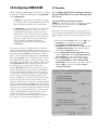
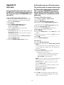
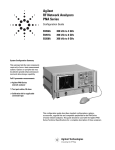
5.1.1.3 Application Output
' Set chan variable to point to the active channel
Set chan = app.ActiveChannel
The figure below shows the displayed results when the
application is executed.
' Set meas variable to point to the active measurement
Set meas = app.ActiveMeasurement
' Setup the channel for a single trigger
chan.Hold True
app.TriggerSignal = naTriggerManual
chan.TriggerMode = naTriggerModeMeasurement
' Make the PNA application visible
app.Visible = True
11
5.1.2 Microsoft Visual Basic Script
Example
5.1.2.1 Application Configuration
Some operating systems may require that the Visual
Basic Scripting engine be installed before running the
application on a PC. To download a free copy of a Visual
Basic Scripting engine, visit the following web site:
http://msdn.microsoft.com/scripting/
5.1.2.2 Application Code
The application code is contained below. The developer
must save the file in a text file (i.e. using notepad) and
save it with the “.vbs” extension. The “.vbs” extension
will tell the operating system to execute the code using
the Visual Basic Scripting engine.
In order to run the application, double-click on the saved
.vbs file. The application can be run on a PC or copied
and run on the PNA Series network analyzer.
' Make the PNA application visible
app.Visible = True
' Set channel parameters
chan.NumberOfPoints = 11
chan.StartFrequency = (1000000000)
chan.StopFrequency = (2000000000)
' Send a manual trigger to initiate a single sweep
chan.Single True
' Store the data in the "result" variable
result = meas.GetData(0, 1)
' Display the result
num_points = chan.NumberOfPoints
For i = 0 To num_points - 1
message = message & result(i) & vbCRLF
Next
if MsgBox(message, vbOKOnly, "S11(dB) - VBS COM
Example for PNA") then
Set chan = Nothing
app.quit
end if
Option Explicit
' Shell objects
Dim app
Dim chan
Dim meas
Dim result
Dim message
Dim num_points
Dim i
5.1.2.3 Application Output
The figure below shows the displayed results when the
application is executed.
' Connect to the PNA application on machine SLTSU044
Set app = CreateObject("AgilentPNA835x.Application",
"SLTSU044")
' Reset the analyzer to instrument preset
app.Reset
' Create S11 measurement
app.CreateMeasurement 1, "S11", 1
' Set chan variable to point to the active channel
Set chan = app.ActiveChannel
' Set meas variable to point to the active measurement
Set meas = app.ActiveMeasurement
' Setup the channel for a single trigger
chan.Hold True
app.TriggerSignal = 3
chan.TriggerMode = 1
12
5.1.3 Microsoft Word Example
5.1.3.1 Application Configuration
Option Explicit
Microsoft® Office 2000 was used for this example. This
version of Office contains Visual Basic for Applications
(VBA) which allows developers to attach Visual Basic
Macros to Word documents. The type library for the
PNA Series network analyzer should be referenced in
the Visual Basic development environment. The following figure illustrates the reference. In this example the
“CreateObject” method will look at the configuration of
DCOM to see what machine to connect to. The code
below must be copied and placed in the Visual Basic editor for the Word document object as shown below.
Dim app
Dim chan
Dim meas
Dim result As Variant
Dim i As Integer
Dim num_points As Integer
Private Sub Document_Open()
' Connect to the PNA application on machine SLTSU044
Set app = CreateObject("AgilentPNA835x.Application")
' Reset the analyzer to instrument preset
app.Reset
' Create S11 measurement
app.CreateMeasurement 1, "S11", 1
' Set chan variable to point to the active channel
Set chan = app.ActiveChannel
' Set meas variable to point to the active measurement
Set meas = app.ActiveMeasurement
' Setup the channel for a single trigger
chan.Hold True
app.TriggerSignal = naTriggerManual
chan.TriggerMode = naTriggerModeMeasurement
' Make the PNA application visible
app.Visible = True
' Set channel parameters
chan.NumberOfPoints = 11
chan.StartFrequency = (1000000000#)
chan.StopFrequency = (2000000000#)
5.1.3.2 Application Code
The application code is contained below. The program
inserts the data retrieved from the analyzer into a table
in a Word document. To run the application, open the
document using Microsoft Word. Enable the macros
when prompted. Once this is complete, the application
will execute and update the document. The application
can be run on a PC or the analyzer.
' Send a manual trigger to initiate a single sweep
chan.Single True
' Store the data in the "result" variable
result = meas.GetData(naRawData,
naDataFormat_LogMag)
' Display the result
num_points = chan.NumberOfPoints
For i = 0 To num_points - 1
ThisDocument.Tables(1).Cell(i + 2, 2).Range = result(i)
Next
Set chan = Nothing
app.Quit
End Sub
13
5.1.3.3 Application Output
5.1.4.2 Application Code
The figure below shows the displayed results when the
application is executed.
The application code is contained below. The program
inserts the data retrieved from the analyzer into cells in
the Excel document. The cells are then used to update a
graph in the Excel document. To run the application,
open the document using Microsoft Excel. Enable
macros when prompted by the application. Once this is
complete, the application will execute and update the
document. It can be run on a PC or the PNA analyzer.
Option Explicit
Dim app
Dim chan
Dim meas
Dim result As Variant
Dim i As Integer
Dim num_points As Integer
Private Sub Workbook_Open()
' Connect to the PNA application on machine SLTSU044
Set app = CreateObject("AgilentPNA835x.Application")
5.1.4 Microsoft Excel Example
5.1.4.1 Application Configuration
Microsoft Office 2000 was used for this example. This
version of Office contains Visual Basic for Applications
(VBA) which allows developers to attach Visual Basic
Macros to Excel documents. The type library for the
PNA network analyzer should be referenced in the
Visual Basic development environment. The following
figure illustrates the reference. In this example the
“Create Object” method will look at the configuration of
DCOM to see what network analyzer to connect to. The
code below must be copied and placed in the Visual
Basic editor for the Excel worksheet object as shown
below.
' Reset the analyzer to instrument preset
app.Reset
' Create S11 measurement
app.CreateMeasurement 1, "S11", 1
' Set chan variable to point to the active channel
Set chan = app.ActiveChannel
' Set meas variable to point to the active measurement
Set meas = app.ActiveMeasurement
' Setup the channel for a single trigger
chan.Hold True
app.TriggerSignal = naTriggerManual
chan.TriggerMode = naTriggerModeMeasurement
' Make the PNA application visible
app.Visible = True
' Set channel parameters
chan.NumberOfPoints = 11
chan.StartFrequency = (1000000000#)
chan.StopFrequency = (2000000000#)
' Send a manual trigger to initiate a single sweep
chan.Single True
' Store the data in the "result" variable
result = meas.GetData(naRawData,
naDataFormat_LogMag)
14
' Display the result
num_points = chan.NumberOfPoints
For i = 0 To num_points - 1
Sheet1.Cells(3 + i, 1) = result(i)
Next
// interface pointers to retrieve COM interfaces
IUnknown* pUnk = 0;
IApplication* pNA = 0;
IChannel* pChan = 0;
IMeasurement* pMeas = 0;
IArrayTransfer* pTrans = 0;
int i, num_points = 0;
float* pScalarData;
Set chan = Nothing
app.Quit
End Sub
HRESULT hr;
5.1.4.3 Application Output
The figure below shows the displayed results when the
application is executed.
// Initialize the COM subsystem
CoInitialize(NULL);
// Create an instance of the network analyzer
// Request the NA's IUnknown interface
hr = CoCreateInstance(CLSID_Application,0,
CLSCTX_ALL,IID_IUnknown, (void**) &pUnk);
if (!FAILED(hr)) {
// QueryInterface for the INetworkAnalyzer interface
of the NetworkAnalyzer object
hr = pUnk->QueryInterface(IID_IApplication,
(void**)&pNA);
if (!FAILED(hr)) {
// Reset the analyzer to instrument preset
pNA->Reset();
// Create S11 measurement
pNA->CreateSParameter(1,1,1,1);
// Set pChan variable to point to the active
channel
pNA->get_ActiveChannel(&pChan);
5.1.5 Microsoft Visual C++ Example
5.1.5.1 Application Configuration
Microsoft Visual C++ version 6 was used for this example. In order to perform this example, create a new project in Microsoft Visual C++. Add a C++ file to the
project and paste the following code into the file. The
path for the type library in the code below should be
changed to reference its location on the development
PC.
if (pChan) {
// Set pMeas variable to point to the active
measurement
pNA->get_ActiveMeasurement(&pMeas);
if(pMeas) {
// Setup the channel for a single trigger
pChan->Hold(true);
pNA->TriggerSignal = naTriggerManual;
pChan->TriggerMode =
naTriggerModeMeasurement;
5.1.5.2 Application Code
The application can be run on a PC or on the PNA.
#include "stdafx.h"
// import the Tsunami type library
//-----------------------------------------------------------------------#import "C:\Program Files\Agilent\Network Analyzer\835x.tlb"
no_namespace, named_guids
int main(int argc, char* argv[])
{
15
// Make the PNA application visible
pNA->put_Visible(true);
// Set channel parameters
pChan->NumberOfPoints = 11;
pChan->StartFrequency = 1e9;
pChan->StopFrequency = 2e9;
// Send a manual trigger to initiate a single
sweep
pChan->Single(true);
// QueryInterface for the IArrayTransfer
interface of the NetworkAnalyzer object
hr = pMeas->QueryInterface(IID_IArray
Transfer, (void**)&pTrans);
if (!FAILED(hr)) {
5.1.6 Agilent VEE Example
5.1.6.1 Application Configuration
For this example use Agilent VEE version 6.0 or above
which contains the Variant data type used to transfer
data from the PNA. The type library for the PNA should
be referenced in the Agilent VEE development environment. The following figure illustrates the reference.
// Store the data in the "result" variable
num_points = pChan->NumberOfPoints;
pScalarData = new float[num_points];
pTrans->getScalar(naRawData, naData
Format_LogMag, (long *)&num_points,
pScalarData);
// Display the result
printf("S11(dB) - Visual C++ COM
Example for PNA\n\n");
for (i = 0; i < num_points; i++)
printf("%f\n",pScalarData[i]);
}
}
}
}
pUnk->Release();
pMeas->Release();
pChan->Release();
pTrans->Release();
pNA->Release();
Using the Agilent VEE Object Browser the developer
can see what classes and methods are available for
development of applications for the PNA Series analyzer
(see below figure).
}
CoUninitialize();
return 0;
}
5.1.5.3 Application Output
The figure below shows the displayed results when the
application is executed.
16
5.1.6.2 Application Code
Agilent VEE version 6.0 or higher must be installed to
run the application in this example. There is a runtime
version of Agilent VEE that may be used if the application has been saved as “runtime”. A free version of
Agilent VEE can be found on the following web site:
http://www.agilent.com/find/vee/. The application may be
run on a PC or on the PNA Series analyzer.
5.1.7 National Instruments™ LabVIEW
Example
5.1.7.1 Application Configuration
Use National Instruments™ Lab VIEW version 5.0 or
above for this example. See the National Instruments™
LabVIEW documentation for information on using
ActiveX objects in the LabVIEW development environment.
5.1.7.2 Application Code
National Instruments™ LabVIEW 5.0 or higher must be
installed to run the application. The application can be
run on a PC or on the PNA Series analyzer.
5.1.6.3 Application Output
The figure below shows the displayed results when the
application is executed.
5.1.7.3 Application Output
The figure below shows the displayed results when the
application is executed.
17
Appendix A:
B) Sharing Drives between a PC and the analyzer.
A) A system administrator grants logon access to
the PNA Series network analyzer for specific user.
This step is also required for COM/DCOM access
from your PC:
This procedure shows an example of how to share
the C drive of the network analyzer with your PC.
This is required for COM/DCOM communication
between your PC and network analyzer. This procedure is detailed in the expanded portion of this
product note.
From the PNA Series Network Analyzer:
From your PNA network analyzer:
1) The system administrator must log on to the PNA
using the administrator username and password.
2) Right-click My Computer
3) Click Manage
4) In the Computer Management window:
• Expand Local Users and Groups
• Right-click on Users
• Click on New User in the pop-up menu
5) In the New User window:
• User name input box, enter the user name used to
• log into your PC with
• Password input box, enter the password used to
log into your PC with
• Re-enter the password for Confirm password
• Click the Create button
• Click the Close button
6) Close the Computer Management window
1) Click Start / Settings / Control Panel
2) Click the System Icon
3) Click the Network Identification Tab
4) Record the analyzer’s Full Computer Name here:
________________________.
5) Click OK to close the System Properties window.
6) Close the Control panel window.
7) Double click the My Computer desktop icon.
8) Single right click on the local C drive.
9) Select Sharing.
10) Under the Sharing tab, select the Share as… radio
button.
11) Type a share name (or use the default C$). Record
the share name here: ______________________.
12) Click OK
13) Close Windows Explorer
Quick Guide
From your PC:
14) Launch Windows Explorer
15) On the main menu bar, click Tools / Map Network
Drive
Your PC will choose the next available drive letter or
you can assign any available drive. Record this drive
letter here__________ .
16) Click in the Path box
Type (or select if available) the path
(\\computername\sharename).
1) You learned your computer name in Step 4.
2) You typed in the share name in step 11.
For example, \\myanalyzer\C$
NOTE: If you are logged onto the Analyzer using the
same logon as your PC, you do not have to enter
“Connect As:”.
To connect under a different user name, type the
name in Connect As.
If the user account is in a different domain, use the
format: domain\username.
If you want to connect to the shared directory
automatically each time you log on, check
Reconnect at Logon.
17) Click OK. The analyzer’s C drive should now be
visible on your PC Windows Explorer as the drive
letter you used in step 15.
18
C) Configure the PNA Series network analyzer to
provide COM/DCOM access to the PNA application for a registered user on the network analyzer.
If you are not a registered user yet, complete step A)
and B) and then return to this step.
From your PNA Series Network Analyzer:
1) Click Start/Run, type dcomcnfg into the input box,
and click OK.
2) Click on Agilent PNA Series in the Applications list,
then click the Properties button.
3) In the Agilent PNA Series Properties window:
• Click the Location tab. Make sure the Run
application on this computer checkbox is
checked.
• Click the Security tab. Click the Use custom
access permissions and Use custom launch
permissions radio buttons.
• Click the Edit... button next to Use custom
access permissions.
4) In the Registry Value Permissions window:
• Click the Add... Button.
5) In the Add Users and Groups window:
• Click Show Users, scroll down and select the user,
then click the Add button.
• Click OK to close the Add Users and Groups
window. Click OK to close the Registry Value
Permissions window.
6) In the Agilent PNA Series Properties window:
• Click the Identity tab. Ensure The interactive user
radio button is selected. Click the OK button.
7) Click the OK button to close the Distributed COM
Configuration Properties window.
From your PC:
1. Using your PC's Windows Explorer, find the
analyzer’s mapped local hard drive (which you found
in step B-15).
2. Click Program Files/Agilent/Network Analyzer/
Automation folder.
3. Double click Automation.vbs and follow the
instructions.
4. A Network Analyzer Setup icon is now setup on
your PC desktop.
Note: Your PC’s operating system may require a Visual
Basic Scripting engine to run the .vbs file. To download a
free copy of a Visual Basic Scripting engine, visit
Microsoft’s® web site:
19
Problems?
When the network analyzer application is installed on
the instrument, the application and all the objects it
serves are registered on that machine. The instrument is
ready to perform as a remote server.
If the analyzer is not working properly, try re-registering
the application and associated libraries through the following steps:
NOTE: The following must be done in the listed order
From your PNA network analyzer:
Find 835x.exe in C:\Program Files\Agilent\Network
Analyzer
1. Select and right-click 835x.exe
2. Select Register COM Server to register the application.
3. Select and right-click 835xps.DLL
4. Select Register COM Server
DCOM settings
5. Click Start
6. Select RUN and type dcomcnfg
7. From the application list, find and select 835X
8. Click Properties
9. Select the Identity tab.
10. Select INTERACTIVE USER
11. Select the Security tab
12. Set permissions and access to CUSTOM
13. Edit the lists to specify the remote user
Agilent Technologies‘
Test and Measurement Support,
Services, and Assistance
By internet, phone, or fax, get assistance
with all your test and measurement needs
Online assistance:
Agilent Technologies aims to maximize the
value you receive, while minimizing your risk
and problems. We strive to ensure that you
get the test and measurement capabilities
you paid for and obtain the support you
need. Our extensive support resources and
services can help you choose the right
Agilent products for your applications and
apply them successfully. Every instrument
and system we sell has a global warranty.
Support is available for at least five years
beyond the production life of the product.
Two concepts underlay Agilent's overall
support policy: "Our Promise" and "Your
Advantage."
Our Promise
Our Promise means your Agilent test and
measurement equipment will meet its advertised performance and functionality. When
you are choosing new equipment, we will
help you with product information, including
realistic performance specifications and
practical recommendations from experienced test engineers. When you use Agilent
equipment, we can verify that it works properly, help with product operation, and provide basic measurement assistance for the
use of specified capabilities, at no extra cost
upon request. Many self-help tools are available.
www.agilent.com/find/assist
Phone or Fax
United States:
(tel) 1 800 452 4844
Canada:
(tel) 1 877 894 4414
(fax) (905) 206 4120
Europe:
(tel) (31 20) 547 2000
Japan:
(tel) (81) 426 56 7832
(fax) (81) 426 56 7840
Latin America:
(tel) (305) 267 4245
(fax) (305) 267 4286
Australia:
(tel) 1 800 629 485
(fax) (61 3) 9272 0749
New Zealand:
(tel) 0 800 738 378
(fax) 64 4 495 8950
Asia Pacific:
(tel) (852) 3197 7777
(fax) (852) 2506 9284
Your Advantage
Your Advantage means that Agilent offers a
wide range of additional expert test and
measurement services, which you can purchase according to your unique technical
and business needs. Solve problems efficiently and gain a competitive edge by contacting with us for calibration, extra-cost
upgrades, out-of-warranty repairs, and onsite education and training, as well as
design, system integration, project management, and other professional services.
Experienced Agilent engineers and technicians worldwide can help you maximize
your productivity, optimize the return on
investment of your Agilent instruments and
systems, and obtain dependable measurement accuracy for the life of those products.
Product specifications and descriptions in
this document subject to change without
notice.
Copyright © 2000
Agilent Technologies
Printed in USA 09/2000
5980-2666EN
Windows and Microsoft are U.S. registered trademarks of Microsoft Corp.