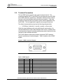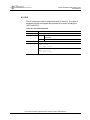
1
FA100-00107
BOARD MANUAL
FAA20 Embedded NEXCOM Vocoder
Board Manual
Document Version 1.0.0
March 2004
Prepared For:
Federal Aviation Administration
William J. Hughes Technical Center
Atlantic City International Airport, NJ 08405
Prepared By:
CIE Engineering, Inc.
600 Maryland Avenue, S.W., Suite 740
Washington, DC 20024
www.cie-eng.com
(202) 484-2298
This document has been prepared by CIE under contract with the Federal Aviation Administration.
FAA20 Embedded NEXCOM Vocoder
Board Manual
Table of Contents
1.0
1.1
1.2
1.3
1.4
2.0
2.1
2.2
3.0
3.1
3.2
3.3
3.4
3.5
4.0
INTRODUCTION.................................................................................................................... 1
Purpose and Scope ........................................................................................................1
References .......................................................................................................................1
Notational Conventions ..................................................................................................1
Document Organization..................................................................................................1
GENERAL DESCRIPTION .................................................................................................... 3
Overview...........................................................................................................................3
Features ............................................................................................................................4
CONNECTORS, CONTROLS, AND INDICATORS.............................................................. 5
Main Signal Connector ...................................................................................................5
Terminal Connectors ......................................................................................................9
Audio Connectors ..........................................................................................................10
LED Indicators ...............................................................................................................11
Switch Controls ..............................................................................................................12
INSTALLATION.................................................................................................................... 13
4.1
Connecting to the FAA20.............................................................................................13
4.2
Setting up Switch Controls ...........................................................................................13
4.3
Setting up Flash Configuration Parameters ..............................................................14
4.3.1
Timing Configuration.............................................................................................14
4.3.2
Setting up the Audio Flow ....................................................................................15
5.0
FUNCTIONAL DESCRIPTION ............................................................................................ 17
5.1
Operational Modes........................................................................................................17
5.1.1
NORM Mode ..........................................................................................................17
5.1.2
VC20 Mode ............................................................................................................17
5.1.3
DEMO Mode ..........................................................................................................18
5.1.4
TEST Mode ............................................................................................................19
5.2
Interfaces ........................................................................................................................19
5.2.1
AUD Interface ........................................................................................................19
5.2.2
PCM Interface ........................................................................................................19
5.2.3
NIB Interface ..........................................................................................................20
5.3
Voice Processing...........................................................................................................22
5.3.1
AMBE+ Vocoder....................................................................................................22
5.3.2
Linear Voice Mixer ................................................................................................24
5.3.3
Packet Voice Router .............................................................................................25
5.3.4
PCM Rate Adapter ................................................................................................25
5.3.5
Tone Generator .....................................................................................................26
5.3.6
Gain, Attenuation, Mute (GAM)...........................................................................27
This manual has been prepared for the Federal Aviation Administration.
FA100-00107 (March 2004) – Rev 1.0.0
Page ii
FAA20 Embedded NEXCOM Vocoder
Board Manual
5.3.7
Voice Activity/Peak Detectors .............................................................................27
5.4
System Timing and Control .........................................................................................28
5.4.1
Truncated Timing Mode .......................................................................................28
5.4.2
Voice Delay ............................................................................................................29
5.4.3
Programmable LEDs ............................................................................................31
5.4.4
Command Processor ............................................................................................33
6.0
ARCHITECTURAL DESCRIPTION..................................................................................... 34
6.1
Hardware Architecture ..................................................................................................34
6.1.1
Hardware Block Diagram .....................................................................................34
6.1.2
Memory Maps ........................................................................................................36
6.2
Software Architecture ...................................................................................................39
6.2.1
Software Block Diagram.......................................................................................39
6.2.2
Tasks and Interrupts .............................................................................................40
6.2.3
Queues, Packets and Data Management .........................................................42
7.0
MAINTENANCE AND TEST................................................................................................ 44
7.1
Troubleshooting Tips ....................................................................................................44
7.2
Test and Integration Tools ...........................................................................................46
7.2.1
Audio Tools ............................................................................................................46
7.2.2
Nibble Tools ...........................................................................................................48
7.2.3
PCM Tools ..............................................................................................................48
7.3
Upgrading FAA20 Software .........................................................................................49
7.3.1
Standard Mode Upgrade......................................................................................49
7.3.2
Acknowledgement Mode Upgrade .....................................................................51
7.4
Vocoder Test Vector Support ......................................................................................53
7.4.1
Test Vector Execution ..........................................................................................53
7.4.2
DAT2LIN Utility ......................................................................................................55
7.4.3
BIT2CMP Utility .....................................................................................................56
8.0
TERMINAL COMMAND REFERENCE............................................................................... 57
8.1
Command Overview .....................................................................................................57
8.2
Built-In Help ....................................................................................................................59
8.3
Command Reference....................................................................................................60
8.3.1
ADAPT....................................................................................................................61
8.3.2
BIT ...........................................................................................................................62
8.3.3
CFG.........................................................................................................................65
8.3.4
CLKDET..................................................................................................................67
8.3.5
CLKRATE ...............................................................................................................68
8.3.6
CLKREF..................................................................................................................70
8.3.7
CLKSRC .................................................................................................................71
8.3.8
COMCFG................................................................................................................72
8.3.9
COMECHO.............................................................................................................73
8.3.10 COMPROMPT.......................................................................................................74
8.3.11 COUNT ...................................................................................................................75
This manual has been prepared for the Federal Aviation Administration.
FA100-00107 (March 2004) – Rev 1.0.0
Page iii
FAA20 Embedded NEXCOM Vocoder
Board Manual
8.3.12
8.3.13
8.3.14
8.3.15
8.3.16
8.3.17
8.3.18
8.3.19
8.3.20
8.3.21
8.3.22
8.3.23
8.3.24
8.3.25
8.3.26
8.3.27
8.3.28
8.3.29
8.3.30
8.3.31
8.3.32
8.3.33
8.3.34
8.3.35
9.0
DELAY.....................................................................................................................77
DM ...........................................................................................................................78
DUMP ......................................................................................................................79
FLASH.....................................................................................................................80
FM............................................................................................................................81
FRAMESIZE ...........................................................................................................82
GAM.........................................................................................................................83
IO .............................................................................................................................84
LED..........................................................................................................................85
LOOP.......................................................................................................................86
MACRO...................................................................................................................87
MCBSP ...................................................................................................................88
MIX...........................................................................................................................89
OPMODE................................................................................................................90
PROG ......................................................................................................................91
REM.........................................................................................................................92
RESET ....................................................................................................................93
ROUTE....................................................................................................................94
TEST .......................................................................................................................95
TONE.......................................................................................................................97
TRUN.......................................................................................................................98
VERSION................................................................................................................99
VOC .......................................................................................................................100
WAIT......................................................................................................................102
GLOSSARY ....................................................................................................................... 103
This manual has been prepared for the Federal Aviation Administration.
FA100-00107 (March 2004) – Rev 1.0.0
Page iv
FAA20 Embedded NEXCOM Vocoder
Board Manual
List of Figures
Figure 1: FAA20 Vocoder Board ...................................................................................................... 3
Figure 2: DIN 41612 Connector Diagram......................................................................................... 5
Figure 3: DB9F Connector Diagram ................................................................................................. 9
Figure 4: VC20 Forced Configuration Items................................................................................... 18
Figure 5: DEMO Forced Configuration Items................................................................................. 18
Figure 6: PCM Interface Timing Diagram ....................................................................................... 19
Figure 7: Nibble Interface Frame Format ....................................................................................... 20
Figure 8: NIB Interface Timing Diagram ......................................................................................... 21
Figure 9: Voice Processing Flow Diagram ..................................................................................... 23
Figure 10: Linear Voice Mixer......................................................................................................... 24
Figure 11: Packet Voice Router...................................................................................................... 25
Figure 12: Rate Adapter Block Diagram......................................................................................... 26
Figure 13: Low Pass Filter Characteristics..................................................................................... 27
Figure 14: Vocoder RUN Signal and Voice Delays........................................................................ 30
Figure 15: FAA20 Hardware Block Diagram .................................................................................. 35
Figure 16: Program Memory Map................................................................................................... 36
Figure 17: Data Memory Map ......................................................................................................... 37
Figure 18: Input/Output Memory Map ............................................................................................ 37
Figure 19: Flash Memory Map........................................................................................................ 38
Figure 20: Software Architecture Diagram ..................................................................................... 40
Figure 21: TEST SWEEP Example ................................................................................................ 47
Figure 22: Software Upgrade (Standard Mode) ............................................................................. 50
Figure 23: Software Upgrade (Acknowledgement Mode) .............................................................. 52
Figure 24: FAA20 Test Vector Setup ............................................................................................. 54
Figure 25: DAT2LIN Utility Command Syntax................................................................................ 55
Figure 26: ASCII Linear Format (L0) .............................................................................................. 55
Figure 27: BIT2CMP Utility Command Syntax ............................................................................... 56
Figure 28: ASCII Compressed Formats (C0 and C1) .................................................................... 56
Figure 29: Built-In Help (Command List)........................................................................................ 59
Figure 30: Built-In Help (Command List)........................................................................................ 59
List of Tables
Table 1: DIN Signals .......................................................................................................................... 6
Table 2: DB9F Signals ....................................................................................................................... 9
Table 3: Audio Jack Signals ............................................................................................................ 10
Table 4: LED Indicators*.................................................................................................................. 11
Table 5: Switch Controls .................................................................................................................. 12
Table 6: Typical Delay Values*........................................................................................................ 30
Table 7: Virtual Indicator List.......................................................................................................... 31
Table 8: Thread List........................................................................................................................ 41
Table 9: Troubleshooting Table ....................................................................................................... 44
Table 10: FAA20 Command Summary .......................................................................................... 57
This manual has been prepared for the Federal Aviation Administration.
FA100-00107 (March 2004) – Rev 1.0.0
Page v
FAA20 Embedded NEXCOM Vocoder
Board Manual
Table 11:
Table 12:
Table 13:
Table 14:
Table 15:
Table 16:
Table 17:
Table 18:
Table 19:
Table 20:
Table 21:
Table 22:
Table 23:
Table 24:
Table 25:
Table 26:
Table 27:
Table 28:
Table 29:
Table 30:
Table 31:
Table 32:
Table 33:
Table 34:
Table 35:
Table 36:
Table 37:
Table 38:
Table 39:
Table 40:
Table 41:
Table 42:
Table 43:
Table 44:
Table 45:
Table 46:
Table 47:
ADAPT Command Syntax.............................................................................................. 61
BIT Command Syntax .................................................................................................... 62
BIT Command Parameters............................................................................................. 63
CFG Command Syntax .................................................................................................. 65
CLKDET Command Syntax............................................................................................ 67
CLKRATE Command Syntax ......................................................................................... 68
CLKREF Command Syntax............................................................................................ 70
CLKSRC Command Syntax ........................................................................................... 71
COMCFG Command Syntax.......................................................................................... 72
COMECHO Command Syntax ....................................................................................... 73
COMPROMPT Command Syntax.................................................................................. 74
COUNT Command Syntax ............................................................................................. 75
DELAY Command Syntax .............................................................................................. 77
DM Command Syntax .................................................................................................... 78
DUMP Command Syntax ............................................................................................... 79
FLASH Command Syntax .............................................................................................. 80
FM Command Syntax..................................................................................................... 81
FRAMESIZE Command Syntax ..................................................................................... 82
FRAMESIZE Command Syntax ..................................................................................... 83
IO Command Syntax ...................................................................................................... 84
LED Command Syntax ................................................................................................... 85
LOOP Command Syntax ................................................................................................ 86
MACRO Command Syntax ............................................................................................ 87
MCBSP Command Syntax ............................................................................................. 88
MIX Command Syntax.................................................................................................... 89
OPMODE Command Syntax.......................................................................................... 90
PROG Command Syntax ............................................................................................... 91
REM Command Syntax .................................................................................................. 92
REM Command Syntax .................................................................................................. 93
ROUTE Command Syntax ............................................................................................. 94
TEST Command Syntax................................................................................................. 95
TONE Command Syntax ................................................................................................ 97
TRUN Command Syntax ................................................................................................ 98
VERSION Command Syntax.......................................................................................... 99
VOC Command Syntax ................................................................................................ 100
VOC Command Parameters ........................................................................................ 101
WAIT Command Syntax ............................................................................................... 102
This manual has been prepared for the Federal Aviation Administration.
FA100-00107 (March 2004) – Rev 1.0.0
Page vi
FAA20 Embedded NEXCOM Vocoder
Board Manual
1.0 INTRODUCTION
This document provides the information needed to integrate and operate
the FAA20 embedded NEXCOM vocoder.
1.1
Purpose and Scope
This document serves the following purpose:
•
Describes FAA20 integration and operation
This manual covers hardware revision B. While the FAA20 software is
designed to run on both platforms (revision A and revision B), there are
minor differences in control bits and interfaces. Revision B has a larger set
of discrete control/status signals and supports a higher serial port data rate.
The board revision level is indicated the printed circuit board (PCB)
silkscreen as part of the board part number. Revision A has the part
number text FA100-00071. Revision B has the part number text FA10000071B.
1.2
References
Reference information include:
•
1.3
DVSI 4.8 kbsp AMBE+TM Vocoder for Air Traffic Communication,
Software Release 1.2.0
Notational Conventions
While reading this manual, the following notational conventions should be
observed:
•
1.4
Command Entry. This manual describes terminal commands. All
terminal commands and responses are shown in courier font.
Although all commands in this manual are shown without the
necessary trailing carriage return, i.e., the user must press the Enter
key to issue the command.
Document Organization
This document contains the following sections:
•
•
•
•
Introduction. This section provides introductory material.
General Description. This section provides a brief overview of the
FAA20 and includes a list of features.
Connectors, Controls, and Indicators. This section provides signal
pinouts and descriptions for all FAA20 connectors and also
describes the operation of FAA20 switches and LEDs.
Installation. This section provides integration guidance.
This manual has been prepared for the Federal Aviation Administration.
FA100-00107 (March 2004) – Rev 1.0.0
Page 1
FAA20 Embedded NEXCOM Vocoder
Board Manual
•
•
•
•
•
Functional Description. This section covers various topics to provide
users with a basic understanding of FAA20 function. It includes
interface operation, voice processing flow details, and timing and
control information.
Architectural Description. This section describes the hardware and
software architectures.
Maintenance and Test. This section includes troubleshooting tips, a
description of test and integration tools, and FAA20 software update
instructions.
Terminal Command Reference. This section includes detailed
FAA20 command information.
Glossary. This section defines abbreviations/acronyms and provides
descriptive text for terms used in this report.
This manual has been prepared for the Federal Aviation Administration.
FA100-00107 (March 2004) – Rev 1.0.0
Page 2
FAA20 Embedded NEXCOM Vocoder
Board Manual
2.0 GENERAL DESCRIPTION
2.1
Overview
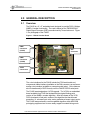
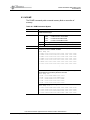
The FAA20 is a 4” x 5” embedded card designed to provide DVSI 4.8 kbps
AMBE+ Vocoder functionality. The card is based on the TMS320C5416
Digital Signal Processor (DSP) manufactured by Texas Instrument. Figure
1 is a photograph of the FAA20.
Figure 1: FAA20 Vocoder Board
DB9F
Connector
(COM1)
LEDs
DIN
Connector
DB9F
Connector
(COM2)
Audio
Connectors
Switches
The voice interfaces for the FAA20 include the PCM serial audio and
compressed nibble interface (available on the DIN connector) as well as an
analog voice interface (available on computer audio jacks). Voice data can
also be transferred (in ASCII format) over the FAA20 RS-232 serial ports.
The FAA20 was designed as a VC20 upgrade. The VC20 is an embedded
board available from DVSI that implements the original floating point
version of the AMBE+ vocoder algorithm. After the release of the VC20,
DVSI developed a fixed point version of the algorithm that has bit exact
properties, i.e. a known input voice vector generates a known output vector.
The FAA20 was produced to use this updated algorithm within NEXCOM
prototyping equipment and to more easily support truncated timing mode.
This manual has been prepared for the Federal Aviation Administration.
FA100-00107 (March 2004) – Rev 1.0.0
Page 3
FAA20 Embedded NEXCOM Vocoder
Board Manual
2.2
Features
The FAA20 features include:
•
•
•
•
•
•
•
•
•
•
•
•
•
•
TMS320C5416-160 High Performance DSP Engine
Dual RS-232 serial ports (supports transfer rates up to 921,600 bps)
Downloadable software (via RS-232 ports)
16-bit Linear Audio Codec with external anti-aliasing filters
Pulse Code Modulated (PCM) Digital Linear Voice Interface
(supports time division multiplexed frame format, external/internal
clocking modes, programmable serial date rates up to 4 Mbps)
Optional Truncated Timing Mode Rate Adapter (adapts standard 8K
linear data to truncated 6.6K rate)
Compressed Nibble Interface (VC20 compatible, internal/external
clocking modes)
Optional Extended Nibble Interface mode (supports virtual COM3
interface using spare bandwidth in the compressed nibble frame)
Forward Error Correction (FEC) status reporting
Built-in Tone Generator and Detector
Five-Port Linear Voice Mixer (vocoder, analog, PCM, tone generator,
and COM port)
Three-Port Compressed Voice Router (vocoder, nibble interface, and
COM port)
Terminal Command Processor with built-in help and flash memory
configuration retention
Programmable LEDs and 8-position configuration switch bank
This manual has been prepared for the Federal Aviation Administration.
FA100-00107 (March 2004) – Rev 1.0.0
Page 4
FAA20 Embedded NEXCOM Vocoder
Board Manual
3.0 CONNECTORS, CONTROLS, AND INDICATORS
This section provides detailed information on the FAA20 connectors,
controls and indicators. The following topics are included:
•
•
•
•
•
Main Signal Connector. Provides signal pinouts and descriptions for
the DIN 41612 connector (96 pins).
Terminal Connectors. Provides signal pinouts and descriptions for
the DB9F connectors (9 pins – 2 each).
Audio Connectors. Provides signal pinouts, descriptions, and
specifications for the two 1/8” audio jacks.
LED Indicators. Describes the default functions for each of the 6
LED indicators. Note: The FAA20 supports programmable LEDs.
Switch Controls. Describes the function of each of the 8 hardware
slide switches.
Figure 1 shows the location of FAA20 connectors, controls and indicators.
3.1
Main Signal Connector
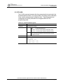
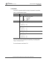
The DIN 41612, 96-pin connector (male) is the main FAA20 signal
connector. It includes audio, PCM, nibble, power, and controls/status
signals. Figure 2 provides a pin location diagram. Table 1 contains a list of
DIN signals. All signals are compatible with standard +5V TTL interfaces.
Figure 2: DIN 41612 Connector Diagram
Note: The FAA20 printed circuit board silkscreen includes the row and pin labels.
This manual has been prepared for the Federal Aviation Administration.
FA100-00107 (March 2004) – Rev 1.0.0
Page 5
FAA20 Embedded NEXCOM Vocoder
Board Manual
Table 1: DIN Signals
SIGNAL
PIN
NIBBLE SIGNALS
ENC3
C4
ENC2
C15
ENC1
C16
ENC0
A4
DIR
DESCRIPTION
O
Encoder Data: The compressed voice data is proved as
a sequence of nibbles from the ATC-10B encoder. A
total of 25 nibbles is provided every vocoder frame. The
first nibble is a control nibble that is nominally set to 0000
(binary). The subsequent 24 nibbles contain the 96-bit
encoded voice data packet. Each nibble is output on the
rising edge of ENCCK. The FMEN encoder frame pulse
is used to initiate the nibble sequence.
Encoder Clock: The encoder clock controls the transfer
of encoder data (ENCx). This signal must be 9600 Hz ±
0.05%. The ENCx, FMEN, GO and RUN are
synchronous with the rising edge of this clock. Either
internal or external clock can be used.
Encoder Frame Enable (active high): The frame enable
is set high for one ENCCK period to begin the transfer of
encoder data. The frame enable is pulsed high once
every 20 ms (normal rate) and delineates the encoding
window. . Either internal or external frame enable can be
used.
Decoder Data: The compressed voice data is provided
as a sequence of nibbles to the ATC-10B decoder. A
total of 25 nibbles is provided every vocoder frame.
Each nibble is read on the falling edge of DECCK. The
FMDE encoder frame pulse is used to initiate the nibble
transfer sequence.
Decoder Clock: The decoder clock controls the transfer
of decoder data (DECx). This signal must be 9600 Hz ±
0.05%. Either internal or external clock can be used.
Decoder Frame Enable (active high): The frame enable
is set high for one ENCCK period to begin the transfer of
encoder data. The frame enable is pulsed high once
every 20 ms (normal rate) and delineates the decoding
window. Either internal or external frame enable can be
used.
ENCCK
A5
I/O
FMEN
C6
I/O
DEC3
DEC2
DEC1
DEC0
C9
C18
C19
A9
I
DECCK
A10
I/O
FMDE
C11
I/O
AUDIO SIGNALS
AVI
A29
I
AVO
O
C29
PCM SIGNALS
DX
B6
O
Analog Speech Input: The analog voice input signal is
filtered with a bandpass filter (100 – 3700 Hz) and
sampled at 8 kHz by a 16-bit codec. The signal should
not exceed ±1 volts peak-to-peak.
Analog Speech Output: A digital-to-analog converter
operating at 8 kHz generates the analog voice output
signal. The signal is bandpass filtered (100 – 3700 Hz)
and should not exceed ±1 volts peak-to-peak.
Serial Transmit Data: Linear 16-bit PCM voice is output
from the FAA20 at a rate of 8000 samples/second. Each
sample is transmitted serially (MSB first) beginning with
the rising edge of the SCLK after the FSX signal is
detected.
This manual has been prepared for the Federal Aviation Administration.
FA100-00107 (March 2004) – Rev 1.0.0
Page 6
FAA20 Embedded NEXCOM Vocoder
Board Manual
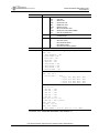
SIGNAL
PIN
DIR
DESCRIPTION
DR
B11
I
SCLK
B9
I/O
FSX
B7
I/O
FSR
B12
I/O
SPRDY
C7
O
Serial Receive Data: Linear 16-bit PCM voice is input to
the FAA20 at a rate of 8000 samples/second. Each
sample is received serially (MSB first) beginning with the
falling edge of the SCLK after the FSR signal is detected.
Serial Shift Clock: The serial shift clock transfers transmit
and receive serial data. Transmit data is output on the
rising edge of clock. Receive data is sampled on the
falling edge of clock.
Serial Transmit Frame Sync (active high): The FAA20
samples this signal on the falling edge of SCLK. An
active signal begins the transfer of Transmit Data. The
FSX signal should be asserted for only one bit period at a
rate of 8 kHz.
Serial Receive Frame Sync (active high): The FAA20
samples this signal on the falling edge of SCLK. An
active signal begins the transfer of Receive Data. The
FSR signal should be asserted for only one bit period at a
rate of 8 kHz.
Serial Port Ready Status: Unlike the VC-20, the FAA20
serial port is dedicated to serial port transfers and is
always ready. This signal is tied to +5V with a pull up
resistor to insure compatibility with VC-20
implementations.
CONTROL/STATUS SIGNALS
RUN
A6
O
Run Status (active high): The FAA20 asserts this signal
when it actively encoding or decoding voice. The signal
is synchronous with ECLK. The FAA20 also lights LED6
when encoding or decoding; however, the LED6 state
changes are driven by the FAA20 DSP and are not
synchronous with ECLK.
Note: This bit is not functional in TEST mode.
RESX
A7
O
Reset Status (active low): The FAA20 asserts this signal
when reset is active. The signal is driven by the FAA20
hardware signal state and not driven by the FAA20 DSP
software. The FAA20 is reset under any of the following
conditions: power up, RSTI assertion, and/or FAA20
watchdog timeout.
DINRS
A15
I
Reset Signal (active high): The reset signal can be
externally asserted to reset the FAA20. An active signal
with a minimum duration of 300 ns resets the board. A
built-in pull-up resister disables this signal when the pin is
left unconnected.
ECHO
A23
I
Echo Canceller Enable (active low): The FAA20 does not
rsvd include a built-in echo canceller. The FAA20 software
ignores this signal. A built-in pull-up resister disables this
signal when the pin is left unconnected.
VAD
A22
I
Voice Detection Enable (active low): This signal must be
asserted to enable FAA20 voice/silence detection and
comfort noise generation. This signal is sampled on the
falling edge of DCLK. A built-in pull-up resister disables
this signal when the pin is left unconnected.
Note: This bit is not functional in TEST mode.
DDET
A17
O
DTMF Detection Status (active high): This signal is not
rsvd used by the FAA20. During power up, it is initialized to
the low (inactive) state.
This manual has been prepared for the Federal Aviation Administration.
FA100-00107 (March 2004) – Rev 1.0.0
Page 7
FAA20 Embedded NEXCOM Vocoder
Board Manual
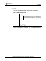
SIGNAL
PIN
DIR
DESCRIPTION
DDAT
A21
O
rsvd
GO
C24
I
TMTX
B32
O
TMRX
B31
I
DTMF Data Output (active high): This signal is not used
by the FAA20. During power up, it is initialized to the low
(inactive) state.
GO Mode (active high): The GO signal must be active to
place the encoder in voice mode. The FAA20 samples
this signal on the falling edge of DCLK when the DFS bit
is also set. When this signal is inactive, the encoder
resets (internally) and outputs silence frames. A built-in
pull-up resister enables this signal when the pin is left
unconnected.
Note: This bit is not functional in TEST mode.
Truncated Timing Status (active high). When set, the
FAA20 is in truncated timing mode.
Note: This bit is not functional in TEST mode.
Truncated Timing Control (active low). When low, causes
the FAA20 to enter truncated timing mode.
Note: This bit is not functional in TEST mode.
Expansion Bits . Reserved for future use.
X00
C32
X01
A24
X02
C25
X03
A25
POWER SIGNALS
VCC
A1, A2,
C1, C2
I/O
rsvd
GND
P
A3, A8,
A13, A20,
A26, A31,
A32, C3,
C8, C13,
C20, C26,
C31, C32
P
Power (positive rail): The FAA20 requires 400 mA (typ)
and 700 mA (max) at +5V ±5%.
Note: Unlike the VC20, the FAA20 does not require an
analog circuit voltage rail.
Power (ground rail): Connect to ground.
* Notes: RW = Read/Write, RO = Read Only, SWC = Software Controlled, RSVD = Reserved, CL =
Clock Latched, and rsvd = reserved for future use. All unlisted pins are not connected.
This manual has been prepared for the Federal Aviation Administration.
FA100-00107 (March 2004) – Rev 1.0.0
Page 8
FAA20 Embedded NEXCOM Vocoder
Board Manual
3.2
Terminal Connectors
The two DB9F serial connectors are used for terminal control. The
connectors labeled UART A and UART B on the silkscreen are the COM1
and COM2 interfaces, respectively. Both/either interface can be used for
terminal control and software download with one exception. If the main
program is erased and the unit is power cycled, the boot application only
uses COM1. The boot application supports main program download.
The default communication setup has the following characteristics:
•
115,200 bps, 8 data bits, 1 stop bit, no parity, no flow control
While this setup facilitates quick setup with three-pin serial cables, it is
recommended that the user enable hardware flow control. Hardware flow
control prevents character loss when printing large sets of data and is also
required for main software download.
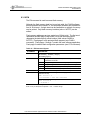
The FAA20 utilizes a data communication equipment (DCE) interface.
Figure 3 provides a pin location diagram. Table 2 contains a list of DB9F
signals.
Figure 3: DB9F Connector Diagram
Table 2: DB9F Signals
SIGNAL
PIN
DIR
DESCRIPTION
CD
RXD
TXD
DTR
GND
DSR
RTS
CTS
RI
1
2
3
4
5
6
7
8
9
O
O
I
I
--O
I
O
O
Carrier Detect. Always active.
Receive Data.
Transmit Data.
Data Terminal Ready.
Ground
Data Send Ready.
Request to Send.
Clear to Send.
Ring Indicator. Always active.
This manual has been prepared for the Federal Aviation Administration.
FA100-00107 (March 2004) – Rev 1.0.0
Page 9
FAA20 Embedded NEXCOM Vocoder
Board Manual
3.3
Audio Connectors
The two 1/8” stereo jacks provide access to the analog audio interface.
The FAA20 only supports a single analog interface, i.e. these jack signals
are wired in common with the associated DIN connector signals.
Although the internal audio amplifier can drive 8-ohm speakers, the
interface is compatible with 600-ohm audio interfaces.
Table 3: Audio Jack Signals
SIGNAL
PIN
DIR
DESCRIPTION
AVI
J8 (tip)
I
Analog Speech Input: The analog voice input signal.
Internally connected to DIN signal pin A29.
Type:
Impedence:
GND
AVO
GND
J8 (sleeve)
J9 (tip)
J9 (sleeve)
--O
---
single-ended
27K ohms
(compatible with 600-ohm)
+3.0 dBm0
100 to 3700 Hz
1 Vpp = 0 dBm0
-23 dBm0 (avg. speech level)
Sinusoidal Overload:
Bandwidth:
Reference Level:
Nominal Level:
Ground.
Analog Speech Output: The analog voice output signal.
Internally connected to DIN signal pin C29.
Type:
Drive Capability:
Sinusoidal Overload:
Bandwidth:
Reference Level:
Nominal Level:
Ground.
single-ended
150 mW (8-ohm load)
+3.0 dBm0
100 to 3700 Hz
1 Vpp = 0 dBm0
-23 dBm0 (avg. speech level)
Note: The audio input jack (J8) is labeled as AUDIO IN. The audio output jack (J9) is labeled as
AUDIO OUT.
This manual has been prepared for the Federal Aviation Administration.
FA100-00107 (March 2004) – Rev 1.0.0
Page 10
FAA20 Embedded NEXCOM Vocoder
Board Manual
3.4
LED Indicators
Table 4 describes the default LED indicator assignments. The FAA20
supports programmable functions for the LEDs. For more information on
LED assignment, see Section 5.4.3.
Table 4: LED Indicators*
LED
ASSIGNMENT
DESCRIPTION
LED1
(red)
LED2
(yellow)
LED3
(green)
LED4
(red)
LANYP
LED5
(yellow)
VAD
LED6
(green)
RUN
Audio Peak Indicator. Lights when audio signal level
reaches the peak threshold, i.e. +3 dBm0.
Audio Activity Indicator. Lights when audio signal level
reaches the peak threshold, i.e. -36 dBm0.
Truncated Timing Indicator. Lights when truncated timing
mode is active.
Error Indicator. Lights when an error is detected. Lights for
each sample/packet added or deleted as a result of timing
differences..
Vocoder Activity Indicator. Lights when voice is detected at
the encoder and the encoder is running –OR—when voice
is detected at the decoder and the decoder is running.
Run Indicator: Blinks when the FAA20 is operating
normally. The blink rate indicates processor loading. Note:
This indicator is NOT related to the RUN signal provided on
the DIN connector.
LANYA
TRUN
ERR
* Default assignments shown. For information regarding LED assignment, refer to Section 5.4.3.
This manual has been prepared for the Federal Aviation Administration.
FA100-00107 (March 2004) – Rev 1.0.0
Page 11
FAA20 Embedded NEXCOM Vocoder
Board Manual
3.5
Switch Controls
Table 5 describes the function of FAA20 switches. These switches are
read only during power up.
Table 5: Switch Controls
SWITCH
SW1
FUNCTION
PCM_MASTER
SW2
NIB_MASTER
SW3
ADAPT_EN
SW4
TRUNC_EN
SW5
PCM_SELECT
SW6
SW7
SW8
Reserved
OPMODE
DESCRIPTION
PCM Master Timing. When ON, the FAA20 generates
PCM timing. When OFF, the external device generates
PCM timing.
Nibble Master Timing. When ON, the FAA20 generates
nibble interface timing. When OFF, the external device
generates nibble timing.
Rate Adapter Enable. When ON and the timing mode is
TRUNCATED, the FAA20 enables the rate adapter on the
PCM interface. Set to ON if the truncated PCM frame rate
is 8000. This switch is ignored for TEST mode.
Truncated Mode Enable. When ON, the FAA20 enters
truncated timing mode. When OFF, the FAA20 enters
normal timing mode. This switch is ignored for TEST
mode.
PCM Select. When ON, the FAA20 routes PCM audio to
the vocoder. When OFF, the FAA20 routes codec audio
to the vocoder. This switch is only read when OPMODE is
set to VC20. This switch is ignored for all other modes.
Reserved. Set to OFF for future compatibility.
Operational Mode: Sets the operational mode of the
FAA20. See Section 5.1 for details.
SW7 SW8
Mode
OFF OFF
NORM Mode.
OFF ON
VC20 Mode.
ON OFF
DEMO Mode.
ON ON
TEST Mode.
This manual has been prepared for the Federal Aviation Administration.
FA100-00107 (March 2004) – Rev 1.0.0
Page 12
FAA20 Embedded NEXCOM Vocoder
Board Manual
4.0 INSTALLATION
This section provides FAA20 installation instructions. The following topics
are included:
•
•
•
Connecting to the FAA20. Provides guidance for board integration.
Setting up Switch Controls. Provides guidance for configuring the
on-board switches.
Setting up Flash Configuration Parameters. Provides guidance for
configuring other FAA20 parameters stored in flash memory.
Before installing and operating the FAA20, review the entire contents of this
manual.
While the FAA20 does possess a terminal command port for control,
configuration and status, the unit is intended to be used as an embedded
device. Operational control is implemented with signal conductors and/or
control bits in the nibble data stream.
4.1
Connecting to the FAA20
The main signal connector is the primary FAA20 interface. Section 0
contains the main connector pinout and signal descriptions. Section 5.2
provides additional interface details and timing diagrams.
4.2
Setting up Switch Controls
The switch controls are read by the FAA20 during unit power up. The
switches control interface timing and operational mode.
To setup the switch controls:
1. Select the operation mode (SW7/SW8).configuration after reviewing
the switch descriptions in Table 5.
Typically, the NORM operational mode is selected (SW7=OFF,
SW8=OFF). This mode will also work with systems designed for the
DVSI VC20 unit.
2. Select the timing sources for the PCM (SW1) and NIB (SW2)
interfaces.
Typically, external timing (switch=OFF) is selected for both
interfaces when the FAA20 is integrated with a host system. Note:
If the PCM interface is not used, the PCM switch setting does not
matter. If the DEMO mode is selected (a standalone mode), insure
both switches are in the ON position.
This manual has been prepared for the Federal Aviation Administration.
FA100-00107 (March 2004) – Rev 1.0.0
Page 13
FAA20 Embedded NEXCOM Vocoder
Board Manual
3. Select the proper adapter configuration (SW3).
This switch setting is important for configurations that use the PCM
interface. If the host system can support both the 8 ksps and 6.67
ksps digital frame rates, set SW3=OFF. If on the other hand, the
host system only supports the standard 8 ksps voice sample rate,
enable the adapter, i.e. set SW3=ON.
4. Select the truncated timing switch (SW4) to the OFF position.
This switch can be used to initially setup the FAA20 in truncated
timing mode. This typically is not desirable, but could be helpful for
system test or demonstration purposes.
5. If VC20 mode has been selected and the PCM interface will be used
with the vocoder, set the PCM route enable switch (SW5) to the ON
position. Otherwise, set the position to OFF.
4.3
Setting up Flash Configuration Parameters
It is recommended that the FAA20 flash configuration parameter settings be
reviewed and updated as required to insure FAA20 interoperability. The
flash configuration parameters settings are accessible via the FAA20
terminal command interface.
To communicate with the FAA20 terminal port for the first time, set up a
terminal to work at 115,200 bps, 8 data bits, 1 stop bit, no parity, no flow
control. The terminal communication parameters can be changed and
saved to flash memory, as required.
To view the current configuration, type the ‘CFG’ command which lists all
configuration parameters. For a list of the default settings, refer to Section
8.3.3.
Since the desired configuration setup is up to the FAA20 integrator, detailed
setup instructions are not provided. However, the following sections
provide additional information which may be helpful in selecting the
appropriate flash configuration.
4.3.1 Timing Configuration
In order to achieve the best audio quality, the proper timing configuration
must be used. The following items provide timing configuration guidance.
•
Clocking (CLKSRC, CLKRATE, FRAMESIZE). Either internal or
external clock (CLKSRC) must be selected for the NIB clock
interface and the optional PCM interface. Since the FAA20 vocoder
is intended to be part of a larger system, external timing is usually
selected. If external clock is selected, the CLKRATE and
FRAMESIZE can be ignored: CLKRATE and FRAMESIZE. If
internal clock is selected, you must insure that the normal and
truncated timing modes support 8 ksps and 6.67 ksps for linear
voice, respectively. In addition, the frame rates for compressed
This manual has been prepared for the Federal Aviation Administration.
FA100-00107 (March 2004) – Rev 1.0.0
Page 14
FAA20 Embedded NEXCOM Vocoder
Board Manual
•
•
voice should be 20 ms and 24 ms, respectively. The nominal nibble
clock rates are 9600 and 8000 Hz, respectively, for normal and
truncated timing modes. For a special framing nibble framing mode
that supports truncated timing at the 9600 Hz rate, see Section 5.2.3
Clock Reference (CLKREF). The CLKREF parameter is used to
control the internal linear voice processing task. The parameter
should be set to match the primary linear port which will be used with
the vocoder, i.e. AUD or PCM.
Rate Adapter (ADAPT). The PCM port rate adapter is designed to
support truncated timing connections for host systems that are
limited to 8 ksps linear voice rates. If enabled, the rate adapter
internally re-samples the PCM audio to create the truncated 6.67
ksps data stream. A rate adapter is not required with the analog
interface. The audio codec sample rate is internally adjusted to the
truncated timing sample rate; thus, the external interface remains
unchanged (except that the signal bandwidth is reduced
accordingly).
For applications which require external NIB timing and use the analog linear
interface, it should be noted that voice samples will be occasionally
added/dropped. This is a result of the small timing differences in the
internal timing base (used to drive audio codec) and the external nibble
timing. Note: This operation is identical with original VC20 implementation.
Other than the CFG command, there are two status tools that can also be
used to verify the timing configuration.
•
•
ERR LED Indicator. The ERR LED lights for each sample/add drop.
If gross timing errors are present, this light will appear solid. For
minor timing variations, this light may blink occasionally.
COUNT Terminal Command. The sample add/delete counters
provide the most detailed information about timing differences.
4.3.2 Setting up the Audio Flow
Just as the proper timing is required for good audio quality; the proper
signal levels are required for good audio quality. And, signal levels are
equally important on the analog and digital audio interfaces. Since audio
level matching can be more problematic, the FAA20 provides an additional
level setting tool on the analog audio interface.
•
•
Voice Signal Levels (GAM, MIX). The recommended average
speech level for the vocoder is -23 dBm0. The gain, attenuation, and
mute (GAM) feature can be used to digitally adjust the AUD (analog)
port signal level. The GAM provides an adjustment of -36 dB to +21
dB. The mixer feature can provide signal attenuation for both analog
and PCM audio signals.
Voice Signal Flow (MIX, ROUTE). Insure the voice signal flows are
configured, as required. For NORM mode, the flash configurations
are used to setup the FAA20 at power up. For the VC20 and DEMO
This manual has been prepared for the Federal Aviation Administration.
FA100-00107 (March 2004) – Rev 1.0.0
Page 15
FAA20 Embedded NEXCOM Vocoder
Board Manual
modes, the flow (MIX & ROUTE) is NOT loaded from flash, but is set
to a known, fixed configuration. For the VC20 mode, however, the
active linear power can be selected with SW5.
In addition to the GAM and MIX level commands, there are LED status
indicators that provide an coarse measure of signal level.
•
LANYP and LANYA LED Indicators. The audio should cause the
LANYA indicator to light and should NOT cause the LANYP peak
indicator to light.
This manual has been prepared for the Federal Aviation Administration.
FA100-00107 (March 2004) – Rev 1.0.0
Page 16
FAA20 Embedded NEXCOM Vocoder
Board Manual
5.0 FUNCTIONAL DESCRIPTION
This section provides a functional overview of the FAA20. The following
topics are included:
•
•
•
•
5.1
Operational Modes. Discusses the normal operational mode and
three other optional modes.
Interfaces. Discusses details for each of the three external voice
port types: the audio interface, the digital PCM interface and the
nibble interface. Interface timing diagrams are provided.
Voice Processing. Presents the overall voice flow block diagram and
describes major blocks/functions in the flow.
System Timing and Control. Discusses truncated timing mode, voice
delays, programmable LEDs and the command processor.
Operational Modes
The FAA20 supports four operational modes. The differences between
modes lie in how the FAA20 routes data and handles vocoder control
signals.
5.1.1 NORM Mode
The NORM mode is used for most FAA20 embedded applications. It
supports the expanded nibble interface and allows flexible routing and voice
signal level adjustments.
5.1.2 VC20 Mode
The VC20 mode is designed to allow the FAA20 to be used with minimal
effort for applications that have been developed based on the VC20. In this
mode, the expanded FAA20 features are disabled and some of the
configuration parameters are forced to a known state, i.e. flash settings are
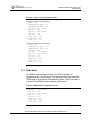
ignored. Figure 4 provides a summary of the VC20 forced configuration
parameters.
This manual has been prepared for the Federal Aviation Administration.
FA100-00107 (March 2004) – Rev 1.0.0
Page 17
FAA20 Embedded NEXCOM Vocoder
Board Manual
Figure 4: VC20 Forced Configuration Items
VC20 Fixed Configuration Items (SW5=OFF)
>
>
>
>
>
>
>
>
>
>
>
ADAPT = OFF
FRAMESIZE NIB NORM = 192
FRAMESIZE NIB TRUN = 192
MIX AUD <- VOC (0x7FFF)
MIX PCM -- OFF
MIX VOC <- AUD (0x7FFF)
MIX COM -- OFF
MIX TON -- OFF
ROUTE VOC <- NIB
ROUTE NIB <- VOC
ROUTE COM <- COM
VC20 Fixed Configuration Items (SW5=ON)
>
>
>
>
>
>
>
>
>
>
>
ADAPT = OFF
FRAMESIZE NIB NORM = 192
FRAMESIZE NIB TRUN = 192
MIX AUD -- OFF
MIX PCM <- VOC (0x7FFF)
MIX VOC <- PCM (0x7FFF)
MIX COM -- OFF
MIX TON -- OFF
ROUTE VOC <- NIB
ROUTE NIB <- VOC
ROUTE COM <- COM
5.1.3 DEMO Mode
The DEMO mode is designed to allow the FAA20 to operate in a
standalone mode. The AUD port is with the vocoder and the compressed
voice packets are internally looped. The software monitors the state of the
TMRX signal to enter and exit truncated timing mode. Figure 5 provides a
summary of the DEMO forced configuration parameters.
Figure 5: DEMO Forced Configuration Items
>
>
>
>
>
>
>
>
MIX AUD <- VOC (0x7FFF)
MIX PCM -- OFF
MIX VOC <- AUD (0x7FFF)
MIX COM -- OFF
MIX TON -- OFF
ROUTE VOC <- VOC
ROUTE NIB <- NIB
ROUTE COM <- COM
This manual has been prepared for the Federal Aviation Administration.
FA100-00107 (March 2004) – Rev 1.0.0
Page 18
FAA20 Embedded NEXCOM Vocoder
Board Manual
5.1.4 TEST Mode
The TEST mode supports FAA20 integration testing. It is especially
designed to allow back-to-back FAA20 unit connection (requires adapter
board). In this mode, the most of the automatic external vocoder controls
are disabled to allow manual control of these items. Specifically, the
following vocoder signal conductors are ignored: VAD, GO, TMRX.
5.2
Interfaces
5.2.1 AUD Interface
There are two physical connections to the audio interface: a DIN
connection and a jack connection. These signals are internally wired
together. If the DIN connector is used as the primary connection interface,
the audio jack can still be used to monitor audio signals.
5.2.2 PCM Interface
The digital PCM interface supports serial, time division multiplexed (TDM)
transmission of digital voice data. A common clock, SCLK, is used for both
data transmission and reception. Frame synchronization signal, FSX and
FSR, enable the transmission and reception of a digital data word,
respectively. Figure 6 provides a signal timing diagram.
Figure 6: PCM Interface Timing Diagra m
SCLK
FSX sampled on falling edge of SCLK
FSX
DX
Data clocked out with rising edge of SCLK
D15 D14 D13 D12 D11 D10 D9
D8
D7
D6
D5
D4
D3
D2
D1
D0
D4
D3
D2
D1
D0
FSX sampled on falling edge of SCLK
FSR
DR
SPRDY
Data sampled on falling edge of SCLK
D15 D14 D13 D12 D11 D10 D9
D8
D7
D6
D5
SPRDY is always high
The SPRDY signal is a vestige of the VC20 digital PCM interface. While
the VC20 required PCM signals to be tri-stated until the unit is ready, the
This manual has been prepared for the Federal Aviation Administration.
FA100-00107 (March 2004) – Rev 1.0.0
Page 19
FAA20 Embedded NEXCOM Vocoder
Board Manual
FAA20 has no such restriction. The SPRDY signal is internally pulled high
with a pull-up resistor.
Although the figure shows alignment of the FSX and FSR signals, this is not
a requirement. The maximum SCLK rate is 4.096 MHz.
The PCM clock rate can be changed “on-the-fly” to support switching
between normal and truncated timing modes; however, the transition
should be glitch-free.
5.2.3 NIB Interface
The FAA20 compressed nibble interface supports the exchange of
compressed voice data. The interface is based on that used within the
VC20; however, the FAA20 supports an expanded set of data and control
nibbles appended to the end of the nibble frame. The expanded interface
provides truncated timing control, error status, and an additional (virtual)
terminal port (COM3). Figure 7 provides the nibble interface frame format.
Figure 7: Nibble Interface Frame Format
VC20 Nibble Field Group
DCS
CVD[23:0]
Expanded Nibble Field Group
FS[1:0] XCS XFEC[3:0] CLEN[1:0]
Control/Status
CDATA[X:0]
COM3 Terminal Data
DCS
DVSI Defined Control/Status Nibble: Vocoder control and status bits. Bit assignments are identical to
VC20. The bit assignments are: DEC3=LOST, DEC2=INIT, DEC1=MUTE, DEC0=rsvd.
CVD
Compressed Voice Data: Contains 23 nibbles (96-bits) of compressed voice data. Nibble orientation
and order are identical to VC20.
FS
Flag Sequence: Set equal to 0xFA. Two nibble field that marks beginning of the Expanded Nibble
Interface. These flag nibbles must be correct for the FAA20 to interpret the remaining nibbles.
XCS
Expanded Control/Status Nibble: Expanded control status nibble used to assert truncation mode and
provide error status. The bit assignments are: DEC3=ESTAT, DEC2=ECLEAR, DEC1=TSTAT,
DEC0=TRUN. The FAA20 uses bit transitions to set the truncation mode. To enable truncated timing
mode, force a zero-to-one bit transition for the TRUN bit in the DECx input data stream. To enable
normal timing mode, force a one-to-zero bit transition. The TSTAT bit (in the ENCx output data
stream) reflects the current timing mode with a 1 indicating truncation is active. A rising edge on the
ECLEAR bit (in the DECx input data stream) forces clearing of any latched errors and clears the FEC
counter.
XFEC
FEC Error Count: For nibble output, represents 16-bit cumulative FEC decoder bit error counter (4
nibbles). Set input = 0000, for future compatibility.
CLEN
Command Length: Length of CDATA expressed as nibbles. Since the CDATA field contains byte
information, the CLEN field is always even. The number of nibbles is twice the number of bytes to be
transmitted. The maximum CLEN value is 128 nibbles (or 64 bytes).
Command Data: Variable length field. Contains ASCII (or binary) bytes for terminal type command
and control. The first nibble is the most significant nibble (MSN) of the first terminal byte. The
second nibble is the least significant nibble (LSN) of the first terminal byte. The next two nibbles
contain the next terminal byte. Subsequent, nibbles contain the remaining terminal data.
CDATA
This manual has been prepared for the Federal Aviation Administration.
FA100-00107 (March 2004) – Rev 1.0.0
Page 20
FAA20 Embedded NEXCOM Vocoder
Board Manual
The FAA20 nibble signaling requirements are identical the VC20 nibble
signaling requirements. Figure 8 provides signal timing information.
Figure 8: NIB Interface Timing Diagram
ENCCK
FMEN sampled on falling edge of ENCCK
Data clocked out with rising edge of ENCCK
FMEN
ENCx
0
CVD CVD CVD CVD CVD CVD CVD CVD CVD CVD CVD CVD CVD CVD CVD CVD CVD
23 22 21 20 19 18 17 16 15 14 13 12 10
9
8
7
6
DECCK
FSX sampled on falling edge of SCLK
FMDE
DECx
Data sampled on falling edge of SCLK
DCS CVD CVD CVD CVD CVD CVD CVD CVD CVD CVD CVD CVD CVD CVD
23 22 21 20 19 18 17 16 15 14 13 12 10 9
The NIB clock rate can be changed “on-the-fly” to support switching
between normal and truncated timing modes; however, the transition
should be glitch-free.
The FAA20 supports a special nibble framing mode for a frame size of 230
clocks. This special mode may enable some host systems that have a
fixed nibble clock rate to support truncated timing mode. As already
presented, the PCM interface provides a rate adapter to perform the
required sample rate adjustment. For the nibble interface, the clock rate
can remain at 9600 Hz and the frame size can be changed to reflect the
truncated timing frame rate. Although the actual frame size required for
truncated timing is not an integral frame size, i.e. 230.4 clocks at 9600 Hz,
the FAA20 supports alternating frame sizes of 230 and 231 clocks to
support an average frame size of 230.4 clocks. Thus, the truncated timing
mode can be supported and compressed packets are not accumulated or
depleted.
When the FAA20 nibble timing source is set to internal, the frame size is set
to 230 for truncated timing mode, and the truncated timing rate is 9600 Hz,
then the FAA20 will generate a special set of framing pulses that average
the 230.4 frame size. Specifically, the following five frame sizes are
repeated sequenced: 230, 231, 230, 230, and 231. Externally timed
interfaces can use the same framing sequence. Audio quality is not
affected since the vocoder is not affected by data transmission methods.
This manual has been prepared for the Federal Aviation Administration.
FA100-00107 (March 2004) – Rev 1.0.0
Page 21
FAA20 Embedded NEXCOM Vocoder
Board Manual
5.3
Voice Processing
The FAA20 voice processing flow includes the following major functional
blocks:
•
•
•
•
•
•
•
AMBE+ Vocoder
Linear Voice Mixer
Packet Voice Router
PCM Rate Adapter
Tone Generator
Gain, Attenuation, and Mute (GAM)
Voice Peak/Activity Detectors
Figure 9 is a voice processing flow diagram. The diagram is divided into
two major areas: linear audio and compressed audio. The AMBE+ vocoder
is positioned between these two areas.
5.3.1 AMBE+ Vocoder
The FAA20 uses the optimized, fixed-point implementation of the DVSI 4.8
kbps Advanced Multi-Band Excitation Plus (AMBE+TM) Vocoder for Air
Traffic Communication. The vocoder is used to compress speech for
transmission over low data rate channels. The AMBE+ algorithm has been
approved for use with the FAA Next Generation Air-to-Ground
Communication System (NEXCOM). The vocoder is also known as the
ATC10B vocoder.
The AMBE+ algorithm has been designed to be robust to both acoustic
background noise and channel errors. It generally contains sufficient
channel error protection to produce high quality speech at bit error rates up
to 1-2% and intelligible speech at bit error rates up to 4-5%.
The algorithm includes a number of advanced features such as automatic
Voice Silence detection (VAD), adaptive comfort noise generation, and softdecision decoding.
There are three sources of vocoder control:
•
•
•
DIN Signal Conductors (GO, VAD)
Control Nibble Bits (INIT, LOST, and MUTE bits)
Terminal Command (VOC command)
The signal and bit states are sampled during the FMDE signal pulse. The
associated control is executed at the beginning of the next call to the
vocoder task. The terminal command states are implemented as soon as
the command is processed.
This manual has been prepared for the Federal Aviation Administration.
FA100-00107 (March 2004) – Rev 1.0.0
Page 22
FAA20 Embedded NEXCOM Vocoder
Board Manual
The FAA20 software actively controls the parameters listed in the VOC
command. This active control is disabled when TEST BITEXACT mode is
enabled. This allows the test vectors supplied at the serial ports to control
the vocoder, as required. For test vector support, see Section 7.4.
Figure 9: Voice Processing Flow Diagram
DIN
AUDIO
PCM_TX
RATE
ADAPTER
D
GAM
CAL
GAM
CAL
AUDIO OUT
D
MIXER
D
AUD
D
PCM
PCM_RX
VOC
COM
LCOM_RX
COM
TON
TONE
GENERATOR
AUDIO IN
D
D
D
LINEAR AUDIO
D
ENCODER
D
DECODER
LCOM_TX
COMPRESSED AUDIO
VOC
NIB_TX
NIB
COM
CCOM_TX
CCOM_RX
NIB_RX
ROUTER
GAM
= Gain/Attenuation/Mute
CAL
= Calibration
D
= Peak/Activity Detector
Note: The rate adapter is available only in truncated timing mode.
This manual has been prepared for the Federal Aviation Administration.
FA100-00107 (March 2004) – Rev 1.0.0
Page 23
FAA20 Embedded NEXCOM Vocoder
Board Manual
5.3.2 Linear Voice Mixer
The linear voice mixer controls the flow of linear voice through the FAA20.
The mixer has five ports: the analog audio port (AUD), the digital PCM port
(PCM), the vocoder port (VOC), the tone generator port (TON), and the
external communication port (COM).
The mixer supports weighted signal summing with saturation control. For
example, if the PCM port is connected to the vocoder, the AUD port can be
configured to sum the PCM TX and RX signals to provide full-duplex audio
monitoring.
The mixed signals are first multiplied by a weighting factor before
summation. The weighting factor is entered as Q1.15 hexadecimal
formatted value; thus, the range is from 0x0000 (off) to 0x7FFF (unity gain).
Figure 10: Linear Voice Mixer
LINEAR VOICE MIXER
AUD
PCM
Port
AUD
Port
PCM
VOC
COM
TON
TON
COM
Port
Port
Mixer
VOC
Port
When controlling the mixer, all transmit and receive signal directions are
referenced at the mixer. In the diagram above, only a receive mixer port is
shown for the tone generator (TON). While an output mixer is provided for
the port, it does not connect to anything (dead-ends) and is thus not shown.
This manual has been prepared for the Federal Aviation Administration.
FA100-00107 (March 2004) – Rev 1.0.0
Page 24
FAA20 Embedded NEXCOM Vocoder
Board Manual
5.3.3 Packet Voice Router
The packet voice router controls the flow of compressed voice packets
through the FAA20. The router has three ports: the vocoder port (VOC),
the nibble port (NIB), and the external communication port (COM).
Figure 11: Packet Voice Router
VOC
Port
Selector
VOC
NIB
NIB
COM
COM
Port
Port
PACKET VOICE ROUTER
Unlike the mixer, each output port can be connected to one and only one
input port. Although the output port is limited to one connection, the input
port can have multiple connections. For example, the VOC input port can
be routed to both the NIB port and the COM port.
Although the router contains three ports, only the NIB and VOC ports are
functional when not in the TEST mode. Only in TEST mode does the
FAA20 software forward packets between the COM queue and the serial
port. In this mode and when TEST BITEXACT is enabled, the queue data
is forwarded to the serial port for vector testing.
5.3.4 PCM Rate Adapter
The PCM rate adapter converts 8 ksps linear voice data to 6.67 ksps, the
sample rate required for truncated timing mode. The rate adapter is useful
for implementations that require constant rate PCM interface while
supporting both normal and truncated timing modes. For example, external
digitally interfaced telecommunication equipment typically supports voice
sampled at a fixed rate of 8 kbps. The rate adapter is supported for the
PCM linear interface only. The analog linear interface does not require a
rate adapter since its sample rate can be adjusted as needed.
The PCM rate adapter is implemented with a multi-rate filter which includes
interpolation, decimation, and filter components. The rate adapter adjusts
the sample rate by the factor L/M, i.e., a ratio of two integers. Since the
truncated timing mode requires a rate reduction from 4.8 kbps to 4.0 kbps
This manual has been prepared for the Federal Aviation Administration.
FA100-00107 (March 2004) – Rev 1.0.0
Page 25
FAA20 Embedded NEXCOM Vocoder
Board Manual
for compressed voice, a rate factor of 5/6 is required. Two filters are
required. The receive filter down-converts the 8 ksps to 6.67 ksps before
sending the data to the encoder. The transmit filter up-converts the 6.67
ksps decoded voice to 8 ksps before sending the data to the PCM output
port. Figure 12 provides a block diagram for the PCM rate adapter.
Figure 12: Rate Adapter Block Diagram
8 ksps
L=5
é
40 ksps
Low Pass Filter
N = 120
6.67 ksps
G=5
Ð
M=6
ê
MIXER/
VOCODER
PCM
M=5
ê
G=6
Ð
Low Pass Filter
N = 120
L=6
é
L = interpolating factor
M = decimating factor
G = gain factor
N = number of FIR filter taps
The interpolator uses the zero-insertion method to maintain spectral purity.
For example, for an interpolation factor of X, every real data sample is
followed by X-1 inserted zero-valued samples. While this approach
maintains spectral purity, it reduces the overall signal level (after filtering)
by a factor equal to the interpolation rate. Thus, a gain adjustment (G) is
required to compensate for signal loss.
The low pass filter characteristics are depicted in Figure 13. The 120-tap
finite impulse response (FIR) filter is designed with a reasonably flat pass
band, a narrow transition band and a small voice delay, i.e. 1.5 ms.
5.3.5 Tone Generator
The tone generator outputs tones in the frequency range of 0 to 0.5 Fs
(where Fs is the sample rate). The resolution is 1 Hz. The output level is
set at 3 dBm0. To route a 0 dBm0 tone out another port, use a mixer value
of 0x5A9D.
This manual has been prepared for the Federal Aviation Administration.
FA100-00107 (March 2004) – Rev 1.0.0
Page 26
FAA20 Embedded NEXCOM Vocoder
Board Manual
Figure 13: Low Pass Filter Characteristics
-20 dB @ 3333 Hz
5 dB/division
5.3.6 Gain, Attenuation, Mute (GAM)
The gain, attenuation, and mute (GAM) block supports a signal adjustment
range of -36 dB to +21 dB for audio signals. Unlike the mixer, the GAM
block supports entries in Q4.12 format; thus, a setting of 0x1000
represents unity gain.
A calibration GAM block is provided to adjust for gain variations in the
analog front end. The calibration settings are programmed at the factory
and are stored in protected boot flash.
5.3.7 Voice Activity/Peak Detectors
The voice activity and peak level detectors are used to light FAA20 voice
activity indicators. There are activity and peak detectors place on all ports
of the mixer. The programmable LEDs can be configured to display any
one of the detectors (see Section 5.4.3). The activity and peak digital
thresholds are set at 0x0200 and 0x7FF0, respectively.
This manual has been prepared for the Federal Aviation Administration.
FA100-00107 (March 2004) – Rev 1.0.0
Page 27
FAA20 Embedded NEXCOM Vocoder
Board Manual
5.4
System Timing and Control
This section addresses the following timing and control topics:
•
•
•
•
Truncated Timing Mode
Voice Delay
Programmable LEDs
Command Processor
5.4.1 Truncated Timing Mode
The truncated timing mode enables the FAA20 to produce a 4.0 kbps
compressed data stream instead of the nominal 4.8 kbps. This lower data
rate is required to support NEXCOM communication when accurate timing
is not available from a ground site.
Truncated timing is implemented using the clock slow-down method. With
this method, the entire FAA20 voice and vocoder operating rate is reduced
by a factor of 5/6. The linear sample rate is reduced from 8.0 ksps to 6.67
ksps. The compressed packet rate is reduced from 50 pps to 41.67 pps.
There are four input controls for truncated timing control:
•
•
•
•
DIN Signal Conductors (TMRX and TMTX signals)
Expanded Control Nibble Bits (TRUN and TSTAT bits)
Terminal Command (TRUN command)
Configuration Switch (TRUN switch – SW4)
The FAA20 uses a first-come, first-serve approach for controlling timing
based on these inputs. For example, the TRUN command can enable
truncated timing, and then the TMRX signal can disable it. Control events
are processed in the order received.
When the DIN signal conductors or the expanded control nibble is used, the
FAA20 switches timing modes during the active state of the FMDE signal.
These two input controls do not function in the TEST operational mode.
When the terminal command is used, the FAA20 switches timing modes as
soon as the command is processed. When the configuration switch is
used, the FAA20 switches timing modes during the power up.
This manual has been prepared for the Federal Aviation Administration.
FA100-00107 (March 2004) – Rev 1.0.0
Page 28
FAA20 Embedded NEXCOM Vocoder
Board Manual
5.4.2 Voice Delay
The software is designed to reduce the overall voice delay through the
FAA20. There are many factors to consider in reducing this delay.
•
•
•
•
•
vocoder execution time
buffering/filtering delays
processor overhead
data transmission speed
vocoder process alignment
Of these factors, vocoder process alignment is the most significant factor in
controlling/minimizing delay. It is controlling the execution start time for the
encoding/decoding tasks based on the timing of the frame sync signals on
the nibble interface. If proper alignment is not maintained, delays can be
easily be increased by up to 20 ms or more, i.e. the width of a compressed
nibble frame. For example, the decoder should start processing a frame
immediately after the frame has been received. The encoder should start
processing voice as late as possible so that the compressed data frame is
ready just before it is needed for transmission.
The FAA20 triggers the encoder/decoder tasks based on known execution
time requirements and the positioning of the compressed nibble frame sync
signals. Execution time requirements for the encoder and decoder vary
based on voice content. In addition, execution times must account for
overhead and higher priority interrupt processing. The higher priority
interrupt processing is required to support hardware data transfers and
useful FAA20 features such as the mixer, voice activity/peak detection, and
GAM volume control. Finally, if both the encoder and decoder tasks
overlap, the FAA20 delays or extends the execution of the decoder task in
favor of minimizing the encoder task execution time.
The vocoder RUN signal (DIN signal pin A6) indicates encoder/decoder
task execution timing (see Figure 14).
The DELAY command prints throughput delays between the linear (AUD or
PCM) and compressed (NIB) interfaces. The reported delay does not
include collection delay (nominally 20 ms) and/or AMBE+ algorithm delay
(nominally 60 ms). Table 6 provides typical delay values for the normal
timing mode.
This manual has been prepared for the Federal Aviation Administration.
FA100-00107 (March 2004) – Rev 1.0.0
Page 29
FAA20 Embedded NEXCOM Vocoder
Board Manual
Figure 14: Vocoder RUN Signal and Voice Delays
20 ms (nominal)
Decode Delay*
Delay
dT
dP
Encode Delay*
dQ
dQ
dP
FMDE
FMEN
Decoder
RUN
Encoder
Decode Delay*
dT
dP
dQ
FMDE
FMEN
Dec
RUN
Encoder
Dec
Overlapping tasks extend the decoder processing delay
Note: Encode and Decode delays shown above are reported by the DELAY command. The delays DO
NOT include collection delay (20 ms) and/or algorithm delay (60 ms).
Table 6: Typical Delay Values*
LED
TYPICAL VALUE
dT
2.6 ms
dP
7.5 ms
5.0 ms
dQ
1.5 ms – 2.0 ms
DESCRIPTION
Transmission Delay. For normal timing and 9600 Hz
clock rate.
Encoder Processing Delay. This is an allocated
maximum delay. It includes processing delay of higher
priority tasks, i.e. interrupts.
Decoder Processing Delay. This is an allocated
maximum delay. It includes processing delay of higher
priority tasks, i.e. interrupts. This delay assumes no
task overlap.
Queue Delay. This is a measured delay. The queue
depths are read at the task trigger point.
* Normal timing mode delays are shown. Truncated timing mode delays are similar.
This manual has been prepared for the Federal Aviation Administration.
FA100-00107 (March 2004) – Rev 1.0.0
Page 30
FAA20 Embedded NEXCOM Vocoder
Board Manual
5.4.3 Programmable LEDs
The FAA20 supports the programmable assignment of virtual indicators to
physical LED indicators. There are 40 virtual indicators and 6 physical
indicators (LED1..LED6).
The virtual indicators fall into four major categories:
•
•
•
•
Audio Indicators. The audio indicators are used to display audio
energy and peak level events. Two of the most commonly used
indicators, LANYP and LANYA, are assigned by default to LED1 and
LED2, respectively. The other audio indicators (which are specific to
certain mixer ports) are useful in troubleshooting mixer and level
setup problems.
Program Task Indicators. The program task indicators are used to
measure software task execution times and interrupt latencies.
These LEDs are typically used only during program development.
Test Indicators. The test indicators are used to troubleshoot unit
integration.
General Indicators. The general indicators display unit operating
conditions, e.g. truncated timing mode and runtime health.
Table 7 provides a brief description of the available virtual indicators. The
audio TX and RX references in the LEDNAME refer to signal directions with
respect to the mixer, i.e. the TX refers a mixer output port and the RX refers
to a mixer input port.
Table 7: Virtual Indicator List
BITNAME
OFF
ON
AUD_HWI
PCM_HWI
NTX_HWI
NRX_HWI
RAT_SWI
LVP_SWI
ENC_SWI
DEC_SWI
CVR_SWI
COM_SWI
TRUN
TYPE*
General
General
Task
Task
Task
Task
Task
Task
Task
Task
Task
Task
General
DESCRIPTION
OFF. Turns LED off.
ON. Turns LED on.
Audio Hardware Interrupt.
PCM Hardware Interrupt.
Nibble Transmit Interrupt.
Nibble Receive Interrupt.
Rate Adapter Software Interrupt.
Linear Voice Processor Software Interrupt.
Encoder Software Interrupt.
Decoder Software Interrupt.
Packet Router Software Interrupt.
UART Polling Software Interrupt.
Truncated Timing Mode. When lit, indicates that the
FAA20 is in truncated timing mode.
This manual has been prepared for the Federal Aviation Administration.
FA100-00107 (March 2004) – Rev 1.0.0
Page 31
FAA20 Embedded NEXCOM Vocoder
Board Manual
BITNAME
TYPE*
DESCRIPTION
LATE_XFSE
Test
LATE_XFSD
Test
LATE_NFS
LAUDTXP
LAUDTXA
LAUDRXP
LAUDRXA
LPCMTXP
LPCMTXA
LPCMRXP
LPCMRXA
LVOCTXP
LVOCTXA
LVOCRXP
LVOCRXA
LCOMTXP
LCOMTXA
LCOMRXP
LCOMRXA
LANYPL
Test
Audio
Audio
Audio
Audio
Audio
Audio
Audio
Audio
Audio
Audio
Audio
Audio
Audio
Audio
Audio
Audio
Audio
LANYP
LANYA
VAD
Audio
Audio
General
RUN
General
ERR
General
Late Encoder Frame Sync. Winks when the encoder
frame size exceeds the associated FRAMESIZE
quantity. Used for debugging the nibble interface.
Late Decoder Frame Sync. Winks when the decoder
frame size exceeds the associated FRAMESIZE
quantity. Used for debugging the nibble interface.
Spare Virtual LED. Not Used.
Transmit Audio Peak.
Transmit Audio Activity.
Receive Audio Peak.
Receive Audio Activity.
Transmit PCM Peak.
Transmit PCM Activity.
Receive PCM Peak.
Receive PCM Activity.
Transmit Vocoder Peak.
Transmit Vocoder Activity.
Receive Vocoder Peak.
Receive Vocoder Activity.
Transmit COM (serial port) Peak.
Transmit COM (serial port) Activity.
Receive COM (serial port) Peak.
Receive COM (serial port) Activity.
Any Voice Signal Peak (Latched). This indicator
latches to the on state when a peak is detected at any
voice signal interface (AUD, PCM, VOC, TON, or
COM).
Any Voice Signal Peak.
Any Voice Signal Activity
Vocoder Voice Activity Detector. Lights when voice is
detected at the encoder and the encoder is running –
OR—when voice is detected at the decoder and the
decoder is running..
Run-time Task Indicator. Blinks at a rate that indicates
overall processor loading. Faster blinking indicates
lighter loading.
Error LED. Lights during error conditions and winks for
sample and packet add/drop events.
Some indicators are static and others are dynamic. For example, the
TRUN indicator is statically lit when the FAA20 enters truncated timing
mode and the LANYP indicator is dynamically winked (briefly lit for a 100
ms period) when a peak event is detected.
The LED assignments are saved in flash configuration memory by the CFG
command. To reassign the LEDs, see Section 8.3.20.
This manual has been prepared for the Federal Aviation Administration.
FA100-00107 (March 2004) – Rev 1.0.0
Page 32
FAA20 Embedded NEXCOM Vocoder
Board Manual
5.4.4 Command Processor
The FAA20 accepts commands from three COM ports, i.e., COM1 through
COM3. The first two command ports are physical RS-232 serial ports. The
third command port is a virtual command port supported over the NIB data
stream. The virtual command port allows host systems to access terminal
control and status without the need for another physical connection.
Three instances of a command processor are run in round-robin fashion.
Characters are collected on each port until a carriage return is detected, i.e.
a full command line has been entered. Then, the command is interpreted
by the command processor. Only one command can be processed per
service event. This guarantees all ports have command access even if one
port heavily loads the system.
The command processor supports a variety of terminal commands. These
commands are described in the terminal command reference (see Section
8.0). All commands are entered in ASCII format and are converted to
uppercase. All responses are preceded by a greater than symbol. A builtin help feature can be accessed to list available command. For each
command, a brief description and valid parameters also can be accessed.
The command processor also handles data transfer required for software
download and vocoder test vector transfer. These data transfers are also
conducted in ASCII format. For software download instructions, see
Section 7.3. For vocoder test vector support, see Section 7.4.
This manual has been prepared for the Federal Aviation Administration.
FA100-00107 (March 2004) – Rev 1.0.0
Page 33
FAA20 Embedded NEXCOM Vocoder
Board Manual
6.0 ARCHITECTURAL DESCRIPTION
This section provides an architectural overview of the FAA20. The
following topics are included:
•
•
6.1
Hardware Architecture. Provides a hardware block diagram and
memory maps.
Software Architecture. Provides a software block diagram and a
description of software tasks and interrupts. Also discusses queues,
packets and data management.
Hardware Architecture
This section presents an overview of the FAA20 hardware design and
includes a set of memory maps.
6.1.1 Hardware Block Diagram
The FAA20 hardware design is based on a TI DSP processor, i.e., the
TMS320VC5416. This processor is required in order to execute the DVSI
optimized software vocoder written in C54x assembly. Figure 15 is a block
diagram of the FAA20 hardware.
The FAA20 supports three voice interfaces: an analog voice interface
(AUD), a digital PCM interface (PCM), and a compressed nibble interface
(NIB).
The analog voice interface is provided by a TI PCM3500 16-bit linear voice
codec. The codec is configured to sample analog voice at either a 8 ksps
(normal timing) or a 6.67 ksps (truncated timing) rate. External operational
amplifiers enable the FAA20 to drive loads as low as 8 ohms. Feedback
components in the front end circuit form a third-order low pass filter used to
band limit the analog voice signal (100 to 3700 Hz). The codec connects to
a DSP multi-channel buffered serial port (MCBSP) and serially shifts data
into and out of the DSP.
The digital PCM interface is used to serially shift data samples directly into
and out of the DSP via MCBSP #1. While not shown in the figure, the
signals are actually buffered through a 5V complex programmable logic
device (CPLD) to provide TTL compatible signaling. The serial port
requires a clock and frame synchronization signals to control data flow.
The frame synchronization signal also functions as a time slot enable signal
for a multi-drop time division multiplexed serial bus.
This manual has been prepared for the Federal Aviation Administration.
FA100-00107 (March 2004) – Rev 1.0.0
Page 34
FAA20 Embedded NEXCOM Vocoder
Board Manual
Figure 15: FAA20 Hardware Block Diagram
AUD
PCM
(digital)
Data/
Clock/
Sync
Data/Clock/Sync
MCBSP1 MCBSP0
DIN
DSP
NIB
TMS320C5416
122.88 MHz
(parallel)
NIBCLK (9.6K typ)
CODEC
PCM3500
OpAmp
Filters
1/8”
Jacks
4.096M or
3.413M
20.48M
MCBSP2
(analog)
DIV5
-orDIV6
OSC
ADDRESS/DATA
Nibbles/Clock/Sync
COM
MCU
I/O
(serial)
UART
TLC16752
FLASH
512 KB
+32 KB
Vocoder Discrete
I/O Controls
DIN
COM1
COM2
DB9
LEDS
SWITCHES
Programmable Logic
(PSD835G & ATF1508)
The nibble interface is supported via a CPLD. The nibble data sampled
with the nibble clock and passed through a double-buffered latch. Data is
transferred out on the rising edge of the nibble clock and transferred in on
the falling edge of the nibble clock. Many of the vocoder discrete control
signals are also sampled by the nibble clock.
The FAA20 includes two different programmable logic devices (PLD): a
CPLD device (Atmel ATF1508) and a combo memory/PLD device (ST
Microelectronics PSD835). The nibble and PCM interface logic is
contained in the CPLD. The address decoding logic and the codec clock
divider circuit is contained in the combo device.
The FAA20 includes a dual port universal asynchronous
receiver/transmitter (UART) device to support two external RS-232 terminal
interfaces.
The UART and PLD devices are located in the DSP IO memory space.
The flash memory is accessed through the DSP data memory space.
This manual has been prepared for the Federal Aviation Administration.
FA100-00107 (March 2004) – Rev 1.0.0
Page 35
FAA20 Embedded NEXCOM Vocoder
Board Manual
6.1.2 Memory Maps
The DSP has three primary address spaces (program memory, data
memory, and IO memory) and four internal memory arrays (DARAM03,
DARAM47, SARAM03, and SARAM47). The DARAM03 array is used in
both the program and data memory spaces. The DARAM47 is presently
unused. The SARAM03 and SARAM47 arrays are used exclusively in the
program memory space.
The flash memory stores the boot application the main application and
configuration parameters. The flash memory is accessed by the DSP in the
data space. The PLD devices support flash memory paging to allow
access to blocks in excess of 32 kbytes.
Memory maps for the three address spaces and the flash device are
provided in Figure 16 through Figure 19.
Figure 16: Program Memory Map
PROGRAM
0x00080
0x00600
MAIN APP
0x07F80
0x08000
IRQ VECTORS
DARAM0 .. DARAM3
0x18000
(Reserved)
DARAM4 .. DARAM7
MAIN APP
SARAM0 .. SARAM3
MAIN APP
SARAM4 .. SARAM7
0x1FFFF
0x28000
0x2FFFF
0x38000
0x3FFFF
> 64K x 16
(main app)
This manual has been prepared for the Federal Aviation Administration.
FA100-00107 (March 2004) – Rev 1.0.0
Page 36
FAA20 Embedded NEXCOM Vocoder
Board Manual
Figure 17: Data Memory Map
0x00000
0x00060
DATA
MEMORY MAP REGS
SCRATCH REGS
0x00080
0x00600
DARAM0 .. DARAM3
DATA
0x07FFF
0x08000
FLASH MEMORY
External Flash Memory
8-bit external memory mapped
into 16-bit data memory space
0x0FFFF
~ 30K x 16 data
Figure 18: Input/Output Memory Map
IO
0x0000
PSD835
CSIOP REGS
0x00FF
0x0100
0x0107
0x0108
0x010F
0x0110
UART A (COM1)
UART B (COM2)
(Reserved)
0x0111
(Reserved)
0x0112
SWITCH BANK
0x0113
(Reserved)
0x011F
0x0120
ATF1508 REG0
0x0121
ATF1508 REG1
0x0122
ATF1508 REG2
This manual has been prepared for the Federal Aviation Administration.
FA100-00107 (March 2004) – Rev 1.0.0
Page 37
FAA20 Embedded NEXCOM Vocoder
Board Manual
Figure 19: Flash Memory Map
FLASH
0x08000
BOOT APP
0x0FFF0
BOOT PARAM
CSBOOT0 .. CSBOOT3
(protected)
0x10000
0x18000
FS0
MAIN APP
0x20000
0x28000
MAIN APP
0x30000
0x38000
MAIN APP
0x40000
0x48000
MAIN APP
FS1 .. FS6
0x50000
0x58000
MAIN APP
0x60000
0x68000
MAIN APP
0x70000
0x78000
MAIN APP
0x80000
0x88000
FS7
CFG PARAM
256K x 8 flash
32K x 8 protected
This manual has been prepared for the Federal Aviation Administration.
FA100-00107 (March 2004) – Rev 1.0.0
Page 38
FAA20 Embedded NEXCOM Vocoder
Board Manual
6.2
Software Architecture
The FAA20 hardware platform houses two different applications: the Boot
Application and the Main Application.
After reset the Boot Application is loaded from protected flash memory
using the built-in, ROM-based boot loader in the ‘C54 processor. This
program then loads and executes the Main Application. The ROM-based
boot loader only supports relatively small programs. The Boot Application
supports large programs loaded from multiple pages of flash memory. In
addition, this protected application supports the upgrade/reprogramming of
the Main Application. The FAA20 always has this core program that can be
used to reload main flash memory, as required.
The remainder of this section describes the FAA20 Main Application.
6.2.1 Software Block Diagram
The FAA20 software is built on the DSP/BIOS operating system. It utilizes
all three types of available interrupts: hardware (HWI), software (SWI), and
periodic (PRD). It has one major runtime task (TSK) that runs the
command processor. Thus, most of the normal operating functions are
executed in the interrupt environment.
Figure 20 is a software architecture diagram for the FAA20 main
application. Software threads (interrupts or tasks) are indicated with
rounded boxes. Queues are indicated with an open box (no sides).
Hardware devices that are external to the software are indicated with threedimensional (3D) boxes. Data communication between threads and
queues are indicated with solid black lines. Control flows are indicated with
red dotted lines.
From a functional standpoint, Figure 20 is divided into three major sections:
Linear Voice, Compressed Voice, and Command & Control. The functions
in the first two sections (the voice processing portion of software
architecture flow) are understandably similar to the voice processing flow
diagram (refer to Figure 9). These functions operate entirely in the
interrupt environment. The last section of the diagram shows the command
and control functions of the software. It contains the only runtime task in
the FAA20 software architecture, i.e., the Command Processor
(CMD_TSK).
This manual has been prepared for the Federal Aviation Administration.
FA100-00107 (March 2004) – Rev 1.0.0
Page 39
FAA20 Embedded NEXCOM Vocoder
Board Manual
Figure 20: Software Architecture Diagram
LINEAR VOICE
PCM
PORT
COMPRESSED VOICE
NIB -TX
PORT
NIB -RX
PORT
NIB -TX ISR
(NTX_HWI)
NIB -RX ISR
(NRX_HWI)
QUE -CNIBTX
QUE -CNIBRX
CODEC
PORT
PCM ISR
(DIG_SWI)
CODEC ISR
(A U D _HWI)
QUE -LDIG
QUE -LAUD
RATE
ADAPTOR
PROCESS
(RAT_SWI)
LINEAR
VOICE
PROCESS
(LVP_SWI)
VOICE
ENCODER
(E N C _SWI)
QUE -LVOCTX
QUE -CVOCRX
QUE -LVOCRX
QUE -CVOCTX
QUE -LPCM
COMPRESSED
VOICE
ROUTER
(CVR_SWI)
VOICE
DECODER
(D E C _SWI)
QUE -LCOM
QUE -CCOM
SYSTEM PERIODIC
TASK
(SYS_PRD)
UARTA
PORT
UART
POLLING
(UART_SWI)
QUE -COM1
QUE -COM2
COMMAND
PROCESSOR
(CMD_TSK)
QUE -COM3
UARTB
PORT
COMMAND & CONTROL
6.2.2 Tasks and Interrupts
Each thread or is briefly described in Table 8. The relative priority of the
task, when active, is also presented. Threads are triggered by hardware
events or by other threads.
This manual has been prepared for the Federal Aviation Administration.
FA100-00107 (March 2004) – Rev 1.0.0
Page 40
FAA20 Embedded NEXCOM Vocoder
Board Manual
Table 8: Thread List
THREAD
↓
DESCRIPTION
RESET_HWI*
NTX_HWI
1
2
NRX_HWI
3
TMR_HWI*
AUD_HWI
4
5
DIG_HWI
6
RAT_SWI
7
LVP_SWI
8
CVR_SWI
n/a
PRD_SWI
COM_SWI
9
n/a
ENC_SWI
10
LED #1 (red). Typically indicates peak audio events.
Transmit Nibble Interrupt. This thread writes nibble data to nibble
interface. It also triggers the ENC_SWI based on data produced
by a vocoder synchronizing function which monitors unit
configuration and the position of the FMEN signal conductor. This
thread is triggered at the falling edge of the ENCCK signal
conductor, i.e. every 106 us (normal timing mode).
Receive Nibble Interrupt. This thread reads nibble data from
nibble interface. It also triggers the DEC_SWI as soon as a voice
packet is com pletely received. This thread is triggered at the
falling edge of the DECCK signal conductor, i.e. every 106 us
(normal timing mode).
Timer Interrupt. This interrupt is managed by the DSP/BIOS.
Audio Codec Interrupt. This interrupt accesses the MCBSP #0
serial port data holding register. It is triggered when an entire data
sample has been received, i.e. every 125 us (normal timing). It
transfers both RX and TX data.
Digital PCM Interrupt. This interrupt accesses the MCBSP #1
serial port data holding register. It is triggered when an entire data
sample has been received, i.e. every 125 us (normal timing). It
transfers both RX and TX data.
Rate Adapter Interrupt. This interrupt performs data rate
adaptation when it is enabled. Otherwise, it passes the data
through unaltered. When the rate adapter is enabled, it is
triggered after the DIG_HWI thread after 6 samples are collected;
otherwise, it is triggered after 5 samples are collected.
Linear Voice Processor. This thread executes all linear voice
processing functions including the mixer, GAM, and activity
detection. Note: The TEST signal functions (like FFT, TONDET,
and SWEEP) are run in the CMD_TSK after a sufficient amount of
data is collected in the COM queue. The LVP_SWI interrupt is
triggered by the AUD_HWI or DIG_HWI when CLKREF is set to
AUD or PCM, respectively. It is triggered for once for every 5
samples.
Packet Voice Router. This thread is presently implemented as
function, i.e. it is not a true thread. It is called by other threads, i.e.
NTX_HWI, NRX_HWI, ENC_SWI, and DEC_HWI. The function is
called by a thread at the entry or exit depending on whether the
thread reads or writes compressed voice packets , respectively.
Periodic Interrupt. This thread is configured to run every 1 ms.
COM Port Polling Service Routine. This thread is presently
implemented as function, i.e. it is not a true thread. It is called
within the SYS_PRD thread. It is runs once every 1 ms.
Encoder. This thread calls the vocoder analysis functions
(encoder). It converts linear voice data to compressed voice data.
It typically completes execution within 7.5 ms (includes the
execution time for higher priority threads). It is triggered once
every 20 ms (normal timing).
This manual has been prepared for the Federal Aviation Administration.
FA100-00107 (March 2004) – Rev 1.0.0
Page 41
FAA20 Embedded NEXCOM Vocoder
Board Manual
THREAD
DEC_SWI
↓
11
KNL_SWI*
CMD_TSK
12
13
IDLE_TSK*
14
DESCRIPTION
Decoder. The function converts linear voice data to compressed
voice data. It typically completes execution within 7.5 ms
(includes the execution time for higher priority threads). It is
triggered once every 20 ms (normal timing).
Kernel. The DSP/BIOS
Command Task. This thread implements the multi-port command
processor. The thread services each COM port in round-robin
fashion. When a complete command line has been received, the
command is executed. A maximum of 1 command is executed
each time a port is serviced.
Idle Task. This idle task runs when no other thread is running.
* This hardware interrupt is not shown in Figure 20.
6.2.3 Queues, Packets and Data Management
Queues are used extensively to pass data between threads. This approach
provides flexible data flows when processes run at different rates. Queues
are sized and controlled to minimize voice delays while still providing some
execution economy.
The processing threads work with data packets, i.e. a set of data. The
queues contain data only, i.e., no headers, footers, or other information.
For the linear voice process (LVP_SWI), the packet size is 5 samples. For
the rate adapter thread (RAT_SWI), the packet size is 5 or 6 samples for
normal or truncated timing, respectively. For the vocoder threads
(ENC_SWI and DEC_SWI), the packet size is 160 samples (nominal). The
COM queues are fairly large to accommodate the amount of binary data
needed to work with the predefined ASCII data formats.
The compressed voice router works with voice frames. Typically, the
compressed frame (packet) size is 12 bytes (96-bits); however, during
BITEXACT testing the frame (packet) size is 48 bytes to allow for up to 4
soft detection bits.
The FAA20 software actively manages queue depths to minimize voice
delays and to compensate for slight timing differences. Both coarse and
fine adjustments are made, as required. Coarse adjustments add/drop data
packets. Fine adjustments add/drop data samples. Together, these events
are referred to as SPAD (sample/packet add/drop) events. Fine
adjustments are only made on linear voice queues, since compressed
queues must work on a complete frames
The management of the QUE_LVOCTX and QUE_LVOCRX queue depths
is the most important since the potential delay impact is large, i.e., the 160
sample frame (packet) represents a 20 ms delay. The queue size is a
multiple of this value. The other queues in the primary voice flow paths are
small, i.e. 13 samples or less.
Queue management also handles slight differences in interface timing via
single sample add/drop events. Figure 20 shows that voice processing
This manual has been prepared for the Federal Aviation Administration.
FA100-00107 (March 2004) – Rev 1.0.0
Page 42
FAA20 Embedded NEXCOM Vocoder
Board Manual
tasks are triggered by different events. If the event timing is not directly
related, timing differences can cause the accumulation/depletion of voice
samples. For example, the AUD_HWI timing is derived from the FAA20
DSP clock and the nibble interface is externally timed, the timing references
are not related. For most queues, if the packet ready or empty size is one
less than required, a sample is added (repeated) or dropped, respectively.
When the vocoder functions (ENC_SWI and DEC_SWI) access the queue,
the built-in, linear window size, calling parameter is used (see DVSI
software vocoder documentation).
For some configurations, SPAD events are normal. For example, when the
analog interface is used with the vocoder and external nibble timing is
enabled, SPAD events normally occur somewhere in the voice path.
Alternatively, when the PCM interface is used with the vocoder and external
timing is used for both the PCM and nibble interface, SPAD events should
not occur.
This manual has been prepared for the Federal Aviation Administration.
FA100-00107 (March 2004) – Rev 1.0.0
Page 43
FAA20 Embedded NEXCOM Vocoder
Board Manual
7.0 MAINTENANCE AND TEST
This section provides an maintenance and test information. The following
topics are included:
•
•
•
•
7.1
Troubleshooting Tips. Includes a troubleshooting table to assist with
problem solving.
Test and Integration Tools. Discusses audio, PCM, and nibble
interface test and integration tools.
Upgrading the FAA20 Software. Provides instructions for loading
new software.
Vocoder Test Vector Support. Provides instructions for running test
vectors through the FAA20. Also includes a description of ASCII test
vector conversion utilities.
Troubleshooting Tips
Table 9 provides troubleshooting tips.
Table 9: Troubleshooting Table
SYMPTOM
No Audio
POTENTIAL
PROBLEMS
Improper Mixer Setup
TROUBLESHOOTING TIPS
•
Use the CFG command to verify current
audio flow and clock settings.
Improper Router Setup
•
Starting at one end of the audio flow, use
the MIX/ROUTE commands to setup
loopbacks to confirm flows through points in
the system. Insure you have proper levels
setup.
•
Use the TONE/MIXER commands to send a
tone out an interface that doesn’t appear to
be working.
•
Insure you have proper timing signals for
digital interfaces. If the timing is working,
you will get interrupts. Use the PROG
command to send interrupt status to the
LEDs, i.e. DIG_HWI, LVP_SWI, etc.
•
If the vocoder is in the path, the nibble
interface MUST have timing. The nibble
interface triggers the vocoder tasks. Thus,
you need nibble timing EVEN IF you are not
using that interface.
•
Insure that the audio peak LED indicator
(typically LED1) is not blinking. If blinking,
refer to associated troubleshooting tips
below.
Use the COUNT command to check for
Failed Front End
Improper Timing Setup
Bad Audio
Improper Timing
Improper Signal Level
•
This manual has been prepared for the Federal Aviation Administration.
FA100-00107 (March 2004) – Rev 1.0.0
Page 44
FAA20 Embedded NEXCOM Vocoder
Board Manual
SYMPTOM
ERR LED
ON Solid
POTENTIAL
PROBLEMS
Large timing offset.
TROUBLESHOOTING TIPS
sample/packet add/drop (SPAD) events.
SPADs should occur no more frequently
than once every few seconds to a minute.
Identify which queues are affected to locate
the timing port problem source.
•
Use the MIX/ROUTE commands to setup
loopbacks to isolate the area that is causing
the bad audio.
•
If the vocoder is in the voice path, check the
vocoder FEC error counter to insure it is not
incrementing, i.e. VOC FEC.
•
Try lowering or raising the audio levels to
see if the condition improves. Note: While
there are peak detectors on the mixer ports,
audio clipping could occur on the far side of
the rate adapter. The adapter filter may
remove the peak levels, but the audio may
still sound bad.
•
Check the power up message banner on
COM1 to see if the flash parameter
configuration is empty. If empty, configure
the unit and use the ‘CFG SAVE’ command
to update the flash.
•
Determine the LED appears solid due to
high number of momentary events or has
been latched on by a spurious event. To do
this, use the command ‘BIT LED4 0’. If this
command clears the condition, a spurious
event occurred (during power up, incidental
events can cause the ERR LED to light.
This is off no concern. If the command does
not clear the LED, used the COUNT
command to see if SPAD events are
occurring.
Spurious error.
Flash Configuration
Empty
ERR LED
occasionally
blinks
Small timing offsets
are present
•
Use the COUNT command to check for
sample/packet add/drop (SPAD) events.
SPADs should occur no more frequently
than once every few seconds to a minute.
Identify which queues are affected to locate
the timing port problem source. For some
system configurations, SPAD events are
normal. See Section 6.2.3.
LANYP LED
Blinks
Audio Level too high
•
To isolate the signal causing the peak event,
use the PROG command to reassign the
general peak LED to specific mixer port
indicators. Adjust the MIX and/or GAM
settings to fix the high audio level problem.
No serial
port comm.
(COM1/
COM2)
Improper terminal
setup
•
The most typical problem may be
incompatible baud rate or hardware flow
control setup. The default setting is 115200
bps,8 data bits,1 stop bit, no parity, and no
flow control.
Failed hardware
This manual has been prepared for the Federal Aviation Administration.
FA100-00107 (March 2004) – Rev 1.0.0
Page 45
FAA20 Embedded NEXCOM Vocoder
Board Manual
7.2
Test and Integration Tools
The FAA20 includes three categories of test and integration tools:
•
•
•
Audio Tools
Nibble Tools
PCM Tools
7.2.1 Audio Tools
There are three types of audio test and integration tools:
•
•
•
Mixer/Router
Tone Generator
Signal Analysis Tools
The mixer and router (see the MIX/ROUTE commands) can be used to
insert loopbacks in the voice processing flow and thus isolate configuration
and timing setup problems.
The tone generator (see the TONE command) can be used to isolate
problems to the transmit or receive path for as specific voice port. Since
the tone generator internally sourced, it is usually used to verify the function
of an output port.
The signal analysis tools, while powerful, are rarely needed to isolate
FAA20 integration problems; however, the tools can provide additional
information. Typically, these tools are used by the factory to isolate
incorrect filter components in the analog front end.
There are three signal analysis tools: a tone detector (TEST TONDET), a
spectrum analyzer (TEST FFT), and a sweep generator/detector (TEST
SWEEP). All three tools use a 64-point fast fourier transform (FFT)
algorithm for frequency analysis. The FAA20 uses the mixer COM port to
collect data needed for analysis because of its large data capacity. Thus,
to use these tools, the signal to be evaluated must be mixed (routed) to the
COM port. The sweep generator has an additional routing requirement. In
order to test the audio front end, it requires that the tone generator be
routed to the AUD mixer port. Figure 21 is a command example illustrating
the use of the sweep generator.
This manual has been prepared for the Federal Aviation Administration.
FA100-00107 (March 2004) – Rev 1.0.0
Page 46
FAA20 Embedded NEXCOM Vocoder
Board Manual
Figure 21: TEST SWEEP Example
COM1: mix off
> MIX AUD -- OFF
> MIX PCM -- OFF
> MIX VOC -- OFF
> MIX COM -- OFF
> MIX TON -- OFF
COM1: mix aud ton 5a9d
> MIX AUD <- TON (0x5A9D)
COM1: mix com aud 7fff
> MIX COM <- AUD (0x7FFF)
COM1: test sweep b
> FREQ 0000 Hz = -81.29 (dBm0)
> FREQ 0125 Hz = -2.07 (dBm0)
> FREQ 0250 Hz = -0.46 (dBm0)
> FREQ 0375 Hz = -0.21 (dBm0)
> FREQ 0500 Hz = -0.14 (dBm0)
> FREQ 0625 Hz = -0.07 (dBm0)
> FREQ 0750 Hz = +0.03 (dBm0)
> FREQ 0875 Hz = +0.08 (dBm0)
> FREQ 1000 Hz = -0.01 (dBm0)
> FREQ 1125 Hz = -0.23 (dBm0)
> FREQ 1250 Hz = -0.50 (dBm0)
> FREQ 1375 Hz = -0.71 (dBm0)
> FREQ 1500 Hz = -0.80 (dBm0)
> FREQ 1625 Hz = -0.88 (dBm0)
> FREQ 1750 Hz = -1.04 (dBm0)
> FREQ 1875 Hz = -1.35 (dBm0)
> FREQ 2000 Hz = -1.77 (dBm0)
> FREQ 2125 Hz = -2.22 (dBm0)
> FREQ 2250 Hz = -2.67 (dBm0)
> FREQ 2375 Hz = -3.13 (dBm0)
> FREQ 2500 Hz = -3.61 (dBm0)
> FREQ 2625 Hz = -4.14 (dBm0)
> FREQ 2750 Hz = -4.74 (dBm0)
> FREQ 2875 Hz = -5.40 (dBm0)
> FREQ 3000 Hz = -6.15 (dBm0)
> FREQ 3125 Hz = -6.93 (dBm0)
> FREQ 3250 Hz = -7.68 (dBm0)
> FREQ 3375 Hz = -8.39 (dBm0)
> FREQ 3500 Hz = -9.23 (dBm0)
> FREQ 3625 Hz = -10.61 (dBm0)
> FREQ 3750 Hz = -12.92 (dBm0)
> FREQ 3875 Hz = -16.28 (dBm0)
COM1:
This manual has been prepared for the Federal Aviation Administration.
FA100-00107 (March 2004) – Rev 1.0.0
Page 47
FAA20 Embedded NEXCOM Vocoder
Board Manual
7.2.2 Nibble Tools
There are three types of NIB test and integration tools:
•
•
•
Nibble Data
COM3 Monitor
BIT Command
For the nibble data interface, the FAA20 supports the generation of a
known nibble test pattern when TEST NTX is enabled. The first voice
nibble is set to 0xF and the remaining nibble values are an incrementing
sequence beginning with 0x1. In addition, the FAA20 also can print the
received nibble frame (see DUMP NRX). Finally, the nibble data interface
supports an external data loopback, e.g. LOOP NIB.
The COM3 monitor is used to troubleshoot the COM3 virtual terminal
interface. When TEST COM3 is enabled, the FAA20 prints all COM3 traffic
to the COM2 port.
The BIT command can be used to manually toggle IO signal conductors;
however, the TEST operational mode must first be enabled to disable
automatic software control.
7.2.3 PCM Tools
The most useful PCM test tool is the external data loopback, i.e LOOP
PCM. In addition, the FAA20 also supports the transmission of an
incrementing data pattern (TEST PCMO ).
This manual has been prepared for the Federal Aviation Administration.
FA100-00107 (March 2004) – Rev 1.0.0
Page 48
FAA20 Embedded NEXCOM Vocoder
Board Manual
7.3
Upgrading FAA20 Software
The FAA20 main application software can be upgraded via any one of the
three terminal ports. Two programming modes are supported: standard
mode (for COM1 or COM2) and acknowledgement mode (for COM3). The
FAA20 application software is provided as an ASCII Motorola S-record file.
The FAA20 includes software to read and interpret S-record command
lines.
7.3.1 Standard Mode Upgrade
The standard upgrade is performed using the plain text file transfer
capability available with most terminal emulation programs.
To upgrade the FAA20 software using COM1 or COM2, complete the
following steps.
1. Verify hardware handshaking is enabled on the terminal and on the
COM port. The COMCFG command can be used to display the
current setup. The last token should be the letter ‘H’ indicating that
hardware handshaking is enabled.
2. Record the current configuration parameter settings. The CFG
command can be used to print the current settings.
If the size of the configuration block in the new software matches
that of the old software, the configuration block is unaffected. If the
sizes are different, the new software will erase the configuration
block. An empty configuration block is reported in the banner
message during FAA20 power up. Typically, the configuration block
does not change with software releases.
3. Enter the PROG command (without any parameters).
The FAA20 erases the main application flash memory to prepare
memory to be reprogrammed. The FAA20 prints READY when this
process has been completed. The FAA20 also temporarily disables
COMECHO and COMPROMPT, if enabled.
4. Send the new S-record file using the terminal file transfer capability.
For example, when TeraTerm Pro is used, this is accomplished by
clicking File→Send File and then selecting the faa20.s file.
The FAA20 updates the terminal display with the number of records
processed. When all records have been transferred without error,
the FAA20 prints a DONE message.
If any error is detected during the programming process, the FAA20
aborts the flash programming and prints an error message. If this
occurs, the file transfer should be stopped and the ESC key should
This manual has been prepared for the Federal Aviation Administration.
FA100-00107 (March 2004) – Rev 1.0.0
Page 49
FAA20 Embedded NEXCOM Vocoder
Board Manual
be pressed to restore the command prompt. The file transfer can be
initiated again by beginning again at step #3.
5. Enter the RESET command to force the FAA20 to load the new
program.
After a few seconds, the FAA20 restarts and prints the banner
message providing the new software build details. Note: If the new
software erases the configuration block (see step #2), the FAA20
prints a configuration memory error, i.e. “ERR FLASH_CFG - using
default”.
6. Reconfigure the FAA20, as necessary, using the information
recorded in step #2.
Figure 22 provides a sample terminal programming session.
Figure 22: Software Upgrade (Standard Mode)
COM1: comcfg
> COMCFG COM1 = 115200,8,1,N,H
> COMCFG COM2 = 115200,8,1,N,D
COM1: prog
> ERASING FLASH (wait for READY)
> READY
> #Records = 1472
> DONE
COM1: reset
> RESET OK
COM1:
Booting...!
>
>
>
>
>
>
>
>
>
>
********************************************************************
*
FAA20: AMBE 4.8 kbps Vocoder (for Air Traffic Communication)
*
********************************************************************
Copyright 2004. CIE Engineering, Inc. All rights reserved.
For more information, contact: www.cie-eng.com
Version: 1.0.0
Built:
Feb 18 2004 15:53:17
Serial#: 617
Type ? for help
COM1:
This manual has been prepared for the Federal Aviation Administration.
FA100-00107 (March 2004) – Rev 1.0.0
Page 50
FAA20 Embedded NEXCOM Vocoder
Board Manual
7.3.2 Acknowledgement Mode Upgrade
The FAA20 supports a virtual command (COM3) port over the nibble
interface (see Section 5.2.3). The acknowledgement mode configures the
FAA20 to print an acknowledgement message after each S-record is
successfully processed. This allows the host equipment to insure the
previous S-record has been successfully processed before transmitting the
next S-record. Note that the COM3 transmission rate is depending on the
nibble interface clock rate and frame size. For a typical setup (9600 Hz and
192 clocks/frame), the average byte transmission rate (not including flash
programming time) is 3000 char/sec.
To upgrade the FAA20 software using COM3, complete the following steps.
1. Send the PROG ACK command.
The FAA20 erases the main application flash memory to prepare
memory to be reprogrammed. The FAA20 prints an ERASING
FLASH message and then prints a READY message when this
process has been completed. The host software should wait for the
READY message before transmitting any S-record lines. Note also
that any other command traffic should be disabled before attempting
a software upgrade.
2. Send the first S-record line.
The FAA20 programs data associated with the record and then
prints an acknowledgement message, > ACK 0000. Always wait for
the FAA20 to acknowledge receipt of the current record before
transmitting the next record.
3. Send the next S-record line.
The FAA20 programs data associated with the line and then prints
an acknowledgement message, > ACK xxxx where xxxx is an
incrementing hex value for each record.
4. Repeat step #3 as necessary until all records are transmitted and
programmed.
The FAA20 continues to print ACK messages. After the last ACK
message, the FAA20 also prints a DONE message. The last record
(an S8 record) in the file indicates the end of the file and includes a
file checksum sequence.
5. Enter the RESET command to force the FAA20 to load the new
program.
After waiting 5 seconds for the power up sequence to complete, a
test command can be issued to the FAA20 to insure the unit has
rebooted.
This manual has been prepared for the Federal Aviation Administration.
FA100-00107 (March 2004) – Rev 1.0.0
Page 51
FAA20 Embedded NEXCOM Vocoder
Board Manual
If any errors are detected during programming (or if an acknowledgement is
not received within 100 ms), send the ESC character (0x1B) followed by a
carriage return (0x0D) to terminate the programming process. The FAA20
does not support S-record retransmission. After insuring the FAA20 has
successfully terminated the process, the programming process can be
reinitiated. To insure the FAA20 has stopped programming, send any other
status command and insure the expected response is provided.
The acknowledgement mode can also be used with COM1 or COM2. The
impact to configuration parameters is the same as described in the
standard mode upgrade (above). In addition, the FAA20 also temporarily
disables COMECHO and COMPROMPT (as above). Also note that the
data transfer rate for COM
Figure 23 provides a sample terminal programming session using COM3.
Note: This sample assumes that COMECHO and COMPROMPT are
enabled on COM3 before beginning the programming sequence. Note: A
banner message is never printed to COM3.
Figure 23: Software Upgrade (Acknowledgement Mode)
COM3: prog ack
> ERASING FLASH (wait for READY)
> READY
> ACK 0000
> ACK 0001
> ACK 0002
…
…
…
> ACK 1470
> ACK 1471
> ACK 1472
> ACK 1472
> DONE
COM3: reset
> RESET OK
COM3:
This manual has been prepared for the Federal Aviation Administration.
FA100-00107 (March 2004) – Rev 1.0.0
Page 52
FAA20 Embedded NEXCOM Vocoder
Board Manual
7.4
Vocoder Test Vector Support
Test vectors are used to insure proper vocoder integration. The vectors
include linear and compressed voice files that are sent through the AMBE
encoder and decoder, respectively. The test vector set also includes a few
vocoder control files that are used to assert controls (e.g. mute, lost, data
window sizes) during test vector execution.
The FAA20 serial interface is designed to work with ASCII commands and
data streams. The binary voice test vector files must be converted to an
ASCII format compatible with the FAA20. There are two MS-DOS style
utilities that perform the conversion.
•
•
DAT2LIN Utility. This utility creates ASCII formatted linear voice
files.
BIT2CMP Utility. This utility creates ASCII formatted compressed
voice files.
Both of these utilities support an option to include a vocoder control file. If a
control file is specified, the utility will interleave FAA20 vocoder setup
commands with the voice data at specified data frame boundaries. The
utilities are designed to accept DVSI-provided ASCII control files (e.g.
lost.ctl). The FAA20 CDROM includes these utilities as well as a batch file
is used to translate all of the necessary vector files.
This section provides the test vector execution procedure and details for the
two MS-DOS utilities.
7.4.1 Test Vector Execution
The FAA20 supports test vector input/output via two RS-232 serial ports.
The test vector execution involves sending an input test vector files into one
serial port of the FAA20 and capturing the converted vector output data at
the other serial port. All output files are compared to insure they are
identical to ones supplied on DVSI software distribution CDROM. Figure 24
shows a typical test vector setup which uses a multi-port serial adapter.
This manual has been prepared for the Federal Aviation Administration.
FA100-00107 (March 2004) – Rev 1.0.0
Page 53
FAA20 Embedded NEXCOM Vocoder
Board Manual
Figure 24: FAA20 Test Vector Setup
Terminal Emulation Software
Tera-Term Pro (Version 2.3)
FAA20 DIN
Loop Adapter
FA100-00184
Test Vectors (Release 1.2.0)
FAA20 Vector Conversion
Utilities and Batch Files
FAA20
Power Supply
FA100-00187
(
RS-232
COMPUTER
USB
KEYSPAN
USA-49W
RS-232
FAA20
FA100-00071
To execute test vectors on the FAA20, complete the following steps:
1. Convert all binary files (from the DVSI software release 1.2.0
CDROM) to ASCII files using the FAA20 ASCII conversion utilities.
For additional information, see Section 7.4.2 and Section 7.4.3.
2. Insure that both command ports, COM1 and COM2, have hardware
flow control enabled. Insure the terminal emulation program also
has hardware flow control enabled.
3. Enter the command ‘TEST BITEXACT ON’ to configure the FAA20
to accept test vectors.
This command stops the real time flow of data to the vocoder,
configures the mixer/router to use the COM ports, and initializes the
vocoder.
4. If the test vector requires DTX mode, manually enter the command
‘VOC DTX ON’.
5. If the test vector requires soft detection bits, manually enter the
command ‘VOC SDBITS x’ where ‘x’ is the required number of bits.
6. Configure the terminal emulation program to capture COM2 terminal
traffic to a file, i.e., the output file.
7. Configure the terminal emulation program to send the ASCII input
file to COM1.
8. When the vector transmission is complete, close the captured
output file and compare it with an ASCII version of the supplied
reference test vector file.
This manual has been prepared for the Federal Aviation Administration.
FA100-00107 (March 2004) – Rev 1.0.0
Page 54
FAA20 Embedded NEXCOM Vocoder
Board Manual
7.4.2 DAT2LIN Utility
The DAT2LIN utility converts binary linear voice files (*.dat and *.syn) to
ASCII linear voice files (*.lin and *.lon). Figure 25 provides the DAT2LIN
command syntax. Figure 26 provides the ASCII linear format.
Figure 25: DAT2LIN Utility Command Syntax
dat2lin [options] infile outfile
Where:
-nocmd
-ctl filename
-h
-q
-qb
disables printing of FAA20 control commands within output stream
Reads control file and uses controls to create output file
Print help
Run in quite mode
Disable banner printing only
Figure 26: ASCII Linear Format (L0)
L0MSSSSXXXX…XXXXEEEE
Where:
M
SSSS
X…X
EEEE
=
=
=
=
Timing Mode (Always = 0 for test vectors)
Sequence number (incrementing hexdata value)
Linear Sample Data (20 samples x 4 char/sample = 80 char)
Checksum
This manual has been prepared for the Federal Aviation Administration.
FA100-00107 (March 2004) – Rev 1.0.0
Page 55
FAA20 Embedded NEXCOM Vocoder
Board Manual
7.4.3 BIT2CMP Utility
The BIT2CMP utility converts binary compressed voice files (*.bit) to ASCII
compressed voice files (*.cmp). The command syntax is shown in Figure
27.
This utility generates two different ASCII output files: one designed for hard
decision detection (1 bit/symbol, format type C0) and one designed for soft
decision detection (4 bits/symbol, format type C1). The vocoder
compressed voice frame contains 96 symbols. The ASCII output formats
are shown in Figure 28.
Figure 27: BIT2CMP Utility Command Syntax
bit2cmp [options] infile outfile
Where:
-nocmd
-ctl filename
-c1
-h
-q
-qb
disables printing of FAA20 control commands within output stream
Reads control file and uses controls to create output file
Selects C1 output format (default is C0 format)
Print help
Run in quite mode
Disable banner printing only
Figure 28: ASCII Compressed Formats (C0 and C1)
C0MSSSSXX…XXEEEE
C1MSSSSYYYY…YYYYEEEE
Where:
M
SSSS
X…X
Y…Y
EEEE
=
=
=
=
=
Timing Mode (Always = 0 for test vectors)
Sequence number (incrementing hexdata value)
Compressed Data (96 symbols x 0.25 char/symbol = 24 char)
Compressed Data (96 symbols x 1 char/symbol = 96 char)
Checksum
This manual has been prepared for the Federal Aviation Administration.
FA100-00107 (March 2004) – Rev 1.0.0
Page 56
FAA20 Embedded NEXCOM Vocoder
Board Manual
8.0 TERMINAL COMMAND REFERENCE
This section provides FAA20 terminal command information. The following
topics are included:
•
•
•
8.1
Command Overview. Describes general usage information and a
command list.
Built-in Help. Describes how to access and use the built-in help
feature.
Command Reference. Provides detailed syntax and operating
information for each of the FAA20 commands.
Command Overview
The FAA20 accepts commands via the serial RS-232 ports or via the virtual
command port (supported over the nibble interface). Commands are
available to control unit clocking, truncation mode, and the routing of
compressed and linear audio. A number of commands are also available to
support troubleshooting and software upgrades.
Table 10 provides a brief description of the available commands. The more
frequently used commands are indicated with a check. After configuration,
the FAA20 operates without any additional terminal control and can be
deeply embedded into host systems.
Table 10: FAA20 Command Summary
COMMAND
ADAPT
BIT
CFG
TYP*
ü
ü
ü
CLKDET
CLKRATE
ü
CLKREF
CLKSRC
ü
ü
COMCFG
ü
COMECHO
COMPROMPT
DESCRIPTION OR USE
Enables/disables the rate adapter during truncated timing
mode.
Sets/gets state of control bits.
Saves/Restores configuration parameters to/from flash
memory.
Prints the detected symbol rates for the internal codec, the
PCM interface and the NIB interface.
Sets/gets the normal/truncated clock rates for the PCM and
NIB interfaces.
Sets/gets the interface used to control linear voice processing.
Sets/gets clock source (internal or external) for the PCM and
NIB interfaces.
Sets/gets communication parameters (baud, start bits, stops
bits, parity, etc) for the two serial RS-232 ports. Note: The
virtual COM port has fixed characteristics.
Controls the echo of typed characters for the three command
ports.
Controls the printing of the prompt for the three command
ports.
This manual has been prepared for the Federal Aviation Administration.
FA100-00107 (March 2004) – Rev 1.0.0
Page 57
FAA20 Embedded NEXCOM Vocoder
Board Manual
COMMAND
REM
COUNT
DELAY
DM
DUMP
FRAMESIZE
FM
GAM
IO
LED
TYP*
ü
ü
ü
ü
ü
LOOP
MACRO
ü
MIX
ü
PROG
RESET
ü
ü
ROUTE
TEST
TONE
TRUN
VERSION
VOC
WAIT
ü
ü
ü
ü
ü
ü
DESCRIPTION OR USE
Forwards command text to virtual COM port.
Prints (or clears) queue-related statistical counters.
Prints current vocoder processing delays.
Writes/reads to/from DSP data memory space.
Prints named memory blocks
Sets/gets the frame size for the PCM and NIB interfaces .
Writes/reads to/from flash memory.
Sets/gets audio interface gain/attenuation/mute level in Q4.12
format.
Writes/reads to/from DSP IO memory space.
Controls mapping of virtual LEDs to the six available physical
LEDs.
Controls audio, PCM, and nibble external loop status.
Enables the user to build a command sequence which can be
played on command or continuously.
Controls the linear voice mixer. Data values are entered in
Q1.15 format.
Prepares the FAA20 to accept a new software program.
Forces a hardware reset by stopping service to the on-board
watchdog timer.
Controls the compressed voice router
Accesses a number of FAA20 test features.
Controls the frequency of the on-board tone generator.
Enables/disables truncated timing mode.
Prints software version information and unit serial number.
Access vocoder controls and status.
Causes the command processor to wait (units = ms).
* TYP = Typical. The checked commands are used by typical FAA20 integrators. The unchecked
commands are primarily used at the factory and are rarely used by FAA20 integrators.
Many commands enable you to set/get parameter status. Typically, to set
the parameter an additional token is provided in the command line, i.e. the
new parameter value. If this token is omitted the current parameter status
is retrieved and displayed. For example, the command ‘ADAPT’, gets the
current parameter setting. The command ‘ADAPT ON’ sets the parameter,
enabling the rate adapter for truncated timing.
Some parameter settings can be saved to flash memory (non-volatile) and
are thus retained between power cycles. These settings are explicitly
saved to flash when the user enters the ‘CFG SAVE’ command. Each
command syntax tables contain a flash attribute which indicates whether
the parameter is saved to flash memory.
Either lower or upper case can be used to enter commands. The FAA20
converts all lines to upper case. All FAA20 responses are prefixed with the
greater than symbol ( > ). All commands and responses are terminated
by a carriage return and all communication is conducted in ASCII format.
This manual has been prepared for the Federal Aviation Administration.
FA100-00107 (March 2004) – Rev 1.0.0
Page 58
FAA20 Embedded NEXCOM Vocoder
Board Manual
8.2
Built-In Help
The FAA20 supports built-in help. The help feature provides command
syntax; thus, it provides a quick reference for using the terminal command
port. The following command reference section not only provides
command syntax, but also provides detailed parameter descriptions.
To access help, type a question mark (?) followed by the ENTER key.
When no additional parameters are specified, a complete list of commands
is printed. For an example of the printed command list, see Figure 29.
Figure 29: Built-In Help (Command List)
COM1: ?
> *****************************************************************
> COMMAND LIST:
>
ADAPT
BIT
CFG
CLKDET
>
CLKRATE
CLKREF
CLKSRC
COMCFG
>
COMECHO
COMPROMPT
COUNT
DELAY
>
DM
DUMP
FLASH
FM
>
FRAMESIZE
GAM
IO
LED
>
LOOP
MACRO
MCBSP
MIX
>
OPMODE
PROG
REM
RESET
>
ROUTE
TEST
TONE
TRUN
>
VERSION
VOC
WAIT
> Type ? followed by space then command for more info
> *****************************************************************
COM1:
To get help on a specific command, type ? followed by the command name.
For example, see Figure 30.
Figure 30: Built-In Help (Command List)
COM1: ? adapt
> *****************************************************************
> ADAPT [ON|OFF] - Controls rate adapter
>******************************************************************
The command help includes parameters and a brief functional description.
This manual has been prepared for the Federal Aviation Administration.
FA100-00107 (March 2004) – Rev 1.0.0
Page 59
FAA20 Embedded NEXCOM Vocoder
Board Manual
8.3
Command Reference
This section provides command syntax and detailed parameter
descriptions. Optional parameters are enclosed in square brackets.
Command parameters that can be saved to flash configuration memory are
noted, accordingly. Command examples are also provided. Commands
are described in alphabetical order.
This manual has been prepared for the Federal Aviation Administration.
FA100-00107 (March 2004) – Rev 1.0.0
Page 60
FAA20 Embedded NEXCOM Vocoder
Board Manual
8.3.1 ADAPT
The ADAPT command enables/disables the PCM rate adapter for truncated
timing mode. The adapter is never enabled in normal timing mode.
Table 11: ADAPT Command Syntax
ATTRIBUTE
DESCRIPTION
SYNTAX
PARAMETERS
ADAPT [onstate]
onstate
ON
Enables rate adapter during truncated timing mode.
OFF
Disables rate adapter during truncated timing mode.
YES
Request the current setting
COM1: adapt
> ADAPT OFF
Enable the rate adapter
COM1: adapt on
> ADAPT ON
FLASH
EXAMPLES
The rate adapter sits in the path between the PCM interface and the linear
mixer. It allows the PCM interface to continue to operate at the nominal
sample rate (8 ksps) while the FAA20 is in truncated timing mode. When
enabled and truncated timing is activated, the audio is converted from the 8
ksps rate to the truncated timing rate of 6.67 ksps, i.e. the sample rate is
adjusted by 5/6. The rate adaptation is achieved through the use of an
interpolating multi-rate filter followed by a decimator. The rate adapter is
only available in truncated timing mode. See Section 5.3.4 for additional
details.
This manual has been prepared for the Federal Aviation Administration.
FA100-00107 (March 2004) – Rev 1.0.0
Page 61
FAA20 Embedded NEXCOM Vocoder
Board Manual
8.3.2 BIT
The BIT command sets/gets bit-based hardware input and output signals.
Typically, bit signals are controlled by the FAA20 software or are used for
factory test purposes. There are some signals that are reserved for future
use, but can be read and/or controlled by the BIT command. Examples
include X03..X00, X03E..X00E, DDAT, DDET, and ECHO. Table 13
provides descriptions for each of the 46 individual bit controls.
Table 12: BIT Command Syntax
ATTRIBUTE
SYNTAX
PARAMETERS
FLASH
EXAMPLES
DESCRIPTION
BIT [bitname [state]]
bitname See Table 13 for list
state
0
Inactive
1
Active
NO
Request current bit states.
COM1: bit
> LED1 = 0 LED2 = 0 LED3
> LED5 = 0 LED6 = 1 LPCM
> LFSD = 0 LFSE = 0 PWDN
> TRUN = 0 WDOG = 1 XFSD
> RUN = 1 DDAT = 0 DDET
> VAD = 0 ECHO = 0 TMTX
> XOE = 0 TS2 = 0 CS1
> X03 = 1 X02 = 1 X01
> X03E = 0 X02E = 0 X01E
> DINR = 0 SPRD = 1 RTS1
> DTR1 = 0 DSR1 = 1 RTS2
> DTR2 = 0 DSR2 = 0
Set DDAT output to active state.
COM1: bit ddat 1
> BIT DDAT = 1
=
=
=
=
=
=
=
=
=
=
=
0
1
0
0
0
0
0
1
0
0
0
LED4
LCVM
LOOP
XFSE
GO
TMRX
CS0
X00
X00E
CTS1
CTS2
=
=
=
=
=
=
=
=
=
=
=
0
1
0
0
1
0
1
1
0
1
0
.
This manual has been prepared for the Federal Aviation Administration.
FA100-00107 (March 2004) – Rev 1.0.0
Page 62
FAA20 Embedded NEXCOM Vocoder
Board Manual
Table 13: BIT Command Parameters
BITNAME
ATTRIBUTES*
DESCRIPTION
LED1
LED2
LED3
RW, SWC
RW, SWC
RW, SWC
LED4
RW, SWC
LED5
LED6
RW, SWC
RW, SWC
LPCM
RW, SWC
LCVM
RW, SWC
LFSD
RW, SWC
LFSE
RW, SWC
PWDN
RW
LOOP
RW
TRUN
RW, SWC
WDOG
RW, SWC
XFSD
RO
XFSE
RO
RUN
RW, SWC
DDAT
RW, CL, RSVD
LED #1 (red). Typically indicates peak audio events.
LED #2 (yellow). Typically indicates audio activity.
LED #3 (green). Typically indicates truncated timing
mode.
LED #4 (red). Typically indicates errors or sample
add/drop events.
LED #5 (yellow). Typically indicates vocoder activity.
LED #6 (green). Typically indicates FAA20 runtime
status.
PCM Timing Master. When set, configures the FAA20
to drive the PCM clock and framing signals.
Note: While the BIT command will directly control the
associated signal direction, other timing dependent
FAA20 functions are not updated by the BIT
command. Therefore, the preferred control method for
PCM master timing is SW1.
Nibble Timing Master. When set, configures the
FAA20 to drive the nibble clock and framing signals.
Note: While the BIT command will directly control the
associated signal direction, other timing dependent
FAA20 functions are not updated by the BIT
command. Therefore, the preferred control method for
PCM master timing is SW2
Local Decoder Frame Sync Control. When LCVM=1,
this bit controls the decoder frame sync signal, FMDE.
Local Encoder Frame Sync Control. When LCVM=1,
this bit controls the encoder frame sync signal, FMEN.
Codec Power Down Control. When set, it powers
down the codec.
Codec External Loop Control. When set, the codec
loops received audio out the transmit port.
Note: When this bit is set, any output provided by the
internal mixer is summed with the looped back input
signal.
Codec Truncated Timing Control. When set, the
codec sample rate is set to 6.67 ksps.
Watch Dog Tickle Control. Toggling of this bit keeps
the watchdog from resetting the processor.
External Decoder Frame Sync Bit. This read-only bit
dis plays the current state of the decoder frame sync
signal, FMDE.
External Encoder Frame Sync Bit. This read-only bit
displays the current state of the encoder frame sync
signal, FMEN.
Vocoder Run Status Signal. When set, indicates that
the encoder and/or decoder process is executing.
Note: For all operational modes except the TEST
mode, this bit is software controlled.
DDAT Signal Control Bit (DTMF Data). Reserved for
future use.
This manual has been prepared for the Federal Aviation Administration.
FA100-00107 (March 2004) – Rev 1.0.0
Page 63
FAA20 Embedded NEXCOM Vocoder
Board Manual
BITNAME
ATTRIBUTES*
DESCRIPTION
DDET
RW, CL, RSVD
GO
RO, CL
VAD
RO, CL
ECHO
RO, CL
TMTX
RW, SWC, CL
TMRX
RO, CL
XOE
RW, RSVD
TS2
X03
X02
X01
X00
X03E
RW, SWC,
RSVD
RW, SWC,
RSVD
RW, SWC,
RSVD
RW, RSVD
RW, RSVD
RW, RSVD
RW, RSVD
RW, RSVD
X02E
RW, RSVD
X01E
RW, RSVD
X00E
RW, RSVD
DINR
RO
SPRD
RO
RTS1
CTS1
DTR1
DSR1
RTS2
CTS2
DTR2
DSR2
RW, SWC
RO
RW, SWC
RO
RW, SWC
RO
RW, SWC
RO
DDET Signal Control Bit (DTMF Detect). Reserved for
future use.
GO Signal Input State. Displays the current state of
the GO input signal.
VAD Signal Input Bit (Voice Activity Detect). Displays
the current state of the VAD input signal.
ECHO Signal Input Bit. Displays the current state of
the ECHO input signal.
Truncated Mode Status Bit. When set, it indicates that
the TMTX signal is active (high).
Note: For all operational modes except the TEST
mode, this bit is software controlled.
Truncated Mode Control Bit. When set, it indicates
that the TMRX signal is active (low).
Expansion Output Group Enable. Reserved for future
use.
Time Slot Enable. When set, it enables two PCM
slots. Use of this bit is reserved for future expansion.
CPLD Clock Mode Bit #1. This bit is reserved for
factory use.
CPLD Clock Mode Bit #0. This bit is reserved for
factory use.
Expansion Bit #3 State. Reserved for future use.
Expansion Bit #3 State. Reserved for future use.
Expansion Bit #3 State. Reserved for future use.
Expansion Bit #3 State.. Reserved for future use.
Expansion Bit #3 Output Enable. Reserved for future
use.
Expansion Bit #2 Output Enable. Reserved for future
use.
Expansion Bit #1 Output Enable. Reserved for future
use.
Expansion Bit #0 Output Enable. Reserved for future
use.
DINR Signal State. Displays the state of the DINRS
signal.
SPRD Signal State. Displays the state of the SPRDY
signal.
Request-to-Send Signal (COM1).
Clear-to-Send Signal State (COM1).
Data Terminal Control Signal (COM1).
Data Send Ready Signal (COM1).
Request-to-Send Signal (COM2).
Clear-to-Send Signal State (COM2).
Data Terminal Control Signal (COM2).
Data Send Ready Signal (COM2).
CS1
CS0
* RW = Read/Write, RO = Read Only, SWC = Software Controlled, RSVD = Reserved, CL = Clock
Latched
This manual has been prepared for the Federal Aviation Administration.
FA100-00107 (March 2004) – Rev 1.0.0
Page 64
FAA20 Embedded NEXCOM Vocoder
Board Manual
8.3.3 CFG
The CFG command displays a list of important FAA20 configuration
settings. It is also used to save and restore flash parameter settings.
When CFG parameters are displayed, all important settings are displayed,
not just the flash configuration parameters.
Table 14: CFG Command Syntax
ATTRIBUTE
DESCRIPTION
SYNTAX
PARAMETERS
CFG [fparam]]
fparam
Configuration Parameter.
SAVE
= Saves settings to flash memory.
RESTORE
= Restores settings from flash memory.
DEFAULT
= Sets FAA20 to factory default.
Note: The SAVE and RESTORE parameters access the
flash, but the DEFAULT parameter does not.
The CFG command reads/writes flash memory.
Save parameters to flash.
COM1: cfg save
> CFG SAVE OK
FLASH
EXAMPLES
Restore parameters from flash.
COM1: cfg restore
> CFG RESTORE OK
Setup FAA20 to factory default.
COM1: cfg default
> CFG DEFAULT OK
Request current configuration information (default settings shown).
COM1: cfg
> ADAPT = ON
> CLKRATE PCM NORM = 3840000
> CLKRATE PCM TRUN = 3840000
> CLKRATE NIB NORM = 9600
> CLKRATE NIB TRUN = 9600
> CLKREF = AUD
> CLKSRC PCM = INT
> CLKSRC NIB = INT
> COMCFG COM1 = 115200,8,1,N,D
> COMCFG COM2 = 115200,8,1,N,D
> COMECHO COM1 = ON
> COMECHO COM2 = ON
> COMECHO COM3 = OFF
> COMPROMPT COM1 = ON
> COMPROMPT COM2 = ON
> COMPROMPT COM3 = OFF
> FRAMESIZE PCM NORM = 480
> FRAMESIZE PCM TRUN = 480
> FRAMESIZE NIB NORM = 192
> FRAMESIZE NIB TRUN = 230
> GAM AUD TX = 0x1000
> GAM AUD RX = 0x1000
> LED 1 = LANYP
This manual has been prepared for the Federal Aviation Administration.
FA100-00107 (March 2004) – Rev 1.0.0
Page 65
FAA20 Embedded NEXCOM Vocoder
Board Manual
ATTRIBUTE
DESCRIPTION
> LED 2 = LANYA
> LED 3 = TRUN
> LED 4 = ERR
> LED 5 = VAD
> LED 6 = RUN
> MIX AUD <- VOC (0x7FFF)
> MIX PCM <- VOC (0x7FFF)
> MIX VOC <- AUD (0x7FFF)
> MIX VOC <- PCM (0x7FFF)
> MIX COM -- OFF
> MIX TON -- OFF
> OPMODE = TEST
Note: OPMODE not saved in flash.
> ROUTE VOC <- NIB
> ROUTE NIB <- VOC
> ROUTE COM <- COM
> TONE = 0 Hz
> TRUN = OFF
Note: TRUN not saved in flash.
> VOC DTX
= 0
This manual has been prepared for the Federal Aviation Administration.
FA100-00107 (March 2004) – Rev 1.0.0
Page 66
FAA20 Embedded NEXCOM Vocoder
Board Manual
8.3.4 CLKDET
The CLKDET command displays measured sampling, frame, and clock
rates for the audio, PCM, and nibble interfaces, respectively.
Table 15: CLKDET Command Syntax
ATTRIBUTE
DESCRIPTION
SYNTAX
PARAMETERS
FLASH
EXAMPLES
CLKDET
None
NO
Print measured rates
COM1: clkdet
> CLKDET AUD = 8000.00
> CLKDET PCM = 7999.99
> CLKDET NTX = 9600.00
> CLKDET NRX = 9599.97
symbols/sec
symbols/sec
symbols/sec
symbols/sec
sampling rate
frame rate
clock rate
clock rate
The rates are determined by measuring the average time between interrupt
events. Since interrupt latencies affect results, a rate is determined over an
average of at least 100 events. The clock accuracy is estimated to be
within 1 symbol/second under normal/typical processor loading.
This manual has been prepared for the Federal Aviation Administration.
FA100-00107 (March 2004) – Rev 1.0.0
Page 67
FAA20 Embedded NEXCOM Vocoder
Board Manual
8.3.5 CLKRATE
The CLKRATE command sets/gets the PCM and NIB interface clock rates
used when internal interface timing is enabled. Two different rates can be
assigned for each interface: one for normal timing mode and one for
truncated timing mode.
Table 16: CLKRATE Command Syntax
ATTRIBUTE
DESCRIPTION
SYNTAX
PARAMETERS
CLKRATE [interface [tmode [rate]]]
interface PCM
Selects the PCM interface
NIB
Selects the NIB interface
tmode
NORM Selects normal timing mode
TRUN Selects truncated timing mode
rate
Des ired clock rate (Hz) entered as a decimal integer.
YES
Print current clock rate settings.
COM1: clkrate
> CLKRATE PCM NORM = 3840000
> CLKRATE PCM TRUN = 3840000
> CLKRATE NIB NORM = 9600
> CLKRATE NIB TRUN = 9600
Print PCM clock rate settings.
COM1: clkrate pcm
> CLKRATE PCM NORM = 3840000
> CLKRATE PCM TRUN = 3840000
FLASH
EXAMPLES
Change NIB clock rate settings for the truncated timing mode.
COM1: clkrate nib trun 8000
> CLKRATE NIB TRUN = 8000
The FAA20 uses the processor’s Multi-channel Buffered Serial Ports
(MCBSPs) to generate interface timing; therefore, clock rates are limited to
values that can be generated using the processor execution clock and a
fixed number of dividers. Note: When external timing is provided, these
limitations do not apply. The FAA20 software automatically determines if
the requested rate can be generated. If the rate cannot be generated, a
parameter error message is printed.
This manual has been prepared for the Federal Aviation Administration.
FA100-00107 (March 2004) – Rev 1.0.0
Page 68
FAA20 Embedded NEXCOM Vocoder
Board Manual
The available PCM clock rates (PCMCLK) are governed by the following
equation:
PCMCLK =
122,880,000
X
where : X = { 1 K 127
}
The available NIB clock rates (NIBCLK) are governed by the following
equation:
NIBCLK =
122,880,000
X ×Y
where : X = { 1 K 256 }
Y=
{ 1 K 512 }
This manual has been prepared for the Federal Aviation Administration.
FA100-00107 (March 2004) – Rev 1.0.0
Page 69
FAA20 Embedded NEXCOM Vocoder
Board Manual
8.3.6 CLKREF
The CLKREF command sets the port which will be used to control timing for
the linear voice processor (LVP) task. The LVP is called after 5 samples
are received on the reference port.
Table 17: CLKREF Command Syntax
ATTRIBUTE
DESCRIPTION
SYNTAX
PARAMETERS
CLKREF [port]
port
PCM
= Digital Data Port
AUD
= Audio Port (default).
YES
Print current clock reference setting.
COM1: clkref
> CLKREF AUD
FLASH
EXAMPLES
Set clock reference to PCM port.
COM1: clkref pcm
> CLKREF PCM
For best vocoder results, this reference should be set equal to the primary
port being used with the vocoder. For example, when the PCM port is
routed to the vocoder, the CLKREF parameter should be set to PCM.
If this setting is not configured properly, timing differences may cause the
FAA20 to insert or delete samples in the primary voice data path. For
example, if the FAA20 is configured to receive voice data on the PCM port
(in external timing mode) and the CLKREF parameter is set to AUD, the
LVP will be timed to the AUD interface (internal timing). With two different
timing references, samples will be accumulated or depleted eventually
causing an insert or drop on a periodic basis that is related to the timing
difference.
This setting does not affect FAA20 operation when the TEST BITEXACT
parameter is set. When this parameter is set, the vocoder does not operate
in real time; thus, adjustments for timing differences are not required.
This manual has been prepared for the Federal Aviation Administration.
FA100-00107 (March 2004) – Rev 1.0.0
Page 70
FAA20 Embedded NEXCOM Vocoder
Board Manual
8.3.7 CLKSRC
The CLKSRC command configures the timing source for timing for the PCM
and NIB ports. Either internal or external timing can be selected. When
internal timing is selected, the FAA20 drives the clock and frame sync
signals for the port. The CLKRATE and FRAMESIZE settings are used to
determine clock and frame rates, respectively.
Table 18: CLKSRC Command Syntax
ATTRIBUTE
DESCRIPTION
SYNTAX
PARAMETERS
CLKSRC [port [dir]]
port
PCM
= Digital Data Port
AUD
= Audio Port (default).
dir
INT
= internal timing
EXT
= external timing
NO
Print current clock source settings.
COM1: clksrc
> CLKSRC PCM = INT
> CLKSRC NIB = INT
Set nibble clock to external.
COM1: clkref nib ext
> CLKREF NIB = EXT
FLASH
EXAMPLES
During power up, the FAA20 always configures the PCM and NIB interface
clock sources based on switches SW1 and SW2, respectively. This can be
changed after power up by using the CLKSRC command.
This manual has been prepared for the Federal Aviation Administration.
FA100-00107 (March 2004) – Rev 1.0.0
Page 71
FAA20 Embedded NEXCOM Vocoder
Board Manual
8.3.8 COMCFG
The COMCFG command configures ASCII communication settings for
serial ports COM1 and COM2, i.e., baud rate, data bits, stop bits, parity,
and flow control. All five parameters must be supplied when updating any
setting.
Table 19: COMCFG Command Syntax
ATTRIBUTE
DESCRIPTION
SYNTAX
PARAMETERS
COMCFG [pid [brate,dbits,sbits,parity,flow]]
pid
COM Port Identifier
1
= COM1
2
= COM2
brate
Baud Rate. Two rates are available.
115200 = Standard rate (default)
921600 = High speed rate.
dbits
Data Bits. Must be set to 8.
sbits
Stop Bits. Must be set to 1.
parity
Parity. Must be none.
N
= None.
flow
Hardware Flow Control.
D
= Disabled (default)
H
= Hardware flow enabled.
YES
Print current communication settings.
COM1: comcfg
> COMCFG COM1 = 115200,8,1,N,D
> COMCFG COM2 = 115200,8,1,N,D
Enable hardware flow control on COM2.
COM1: comcfg 2 115200,8,1,n,h
> COMCFG COM2 = 115200,8,1,N,H
FLASH
EXAMPLES
This serial port configuration command only applies to the physical ports
COM1 and COM2. The virtual command port (COM3) uses the
synchronous nibble interface, so ASCII communication settings are not
applicable.
While hardware flow control is disabled to allow quick connection with
three-wire terminal interfaces, it is recommended that hardware flow control
be enabled for best performance. Hardware flow control is required for
software download and will insure that characters are not dropped for large
printouts, i.e. CFG command response.
This manual has been prepared for the Federal Aviation Administration.
FA100-00107 (March 2004) – Rev 1.0.0
Page 72
FAA20 Embedded NEXCOM Vocoder
Board Manual
8.3.9 COMECHO
The COMECHO command enables/disables local character echo for
terminal interfaces.
Table 20: COMECHO Command Syntax
ATTRIBUTE
DESCRIPTION
SYNTAX
PARAMETERS
COMECHO [pid [onstate]]
pid
COM Port Identifier
1
= COM1
2
= COM2
3
= COM3 (virtual terminal over nibble interface)
onstate
ON
Enables local character echo.
OFF
Disables local character echo.
YES
Print current echo settings (default settings shown).
COM1: comecho
> COMECHO COM1 = ON
> COMECHO COM2 = ON
> COMECHO COM3 = OFF
Disable character echo on COM2.
COM1: comecho 2 off
> COMECHO COM2 = OFF
FLASH
EXAMPLES
This manual has been prepared for the Federal Aviation Administration.
FA100-00107 (March 2004) – Rev 1.0.0
Page 73
FAA20 Embedded NEXCOM Vocoder
Board Manual
8.3.10 COMPROMPT
The COMPROMPT command enables/disables the printing of a prompt
string at the terminal interface.
Table 21: COMPROMPT Command Syntax
ATTRIBUTE
DESCRIPTION
SYNTAX
PARAMETERS
COMPROMPT [pid [onstate]]
pid
COM Port Identifier
1
= COM1
2
= COM2
3
= COM3 (virtual terminal over nibble interface)
onstate
ON
Enables prompt.
OFF
Disables prompt.
YES
Print current prompt settings (default settings shown).
COM1: comprompt
> COMPROMPT COM1 = ON
> COMPROMPT COM2 = ON
> COMPROMPT COM3 = OFF
Disable prompt on COM2.
COM1: comprompt 2 off
> COMPROMPT COM2 = OFF
FLASH
EXAMPLES
This manual has been prepared for the Federal Aviation Administration.
FA100-00107 (March 2004) – Rev 1.0.0
Page 74
FAA20 Embedded NEXCOM Vocoder
Board Manual
8.3.11 COUNT
The COUNT command prints counters associated with internal message
queues.
Table 22: COUNT Command Syntax
ATTRIBUTE
DESCRIPTION
SYNTAX
PARAMETERS
COUNT [cvalue]
cvalue
Clear Count Value.
0
= Zero clears all counters
NO
Print current counter settings.
COM1: count
> QUEID SADD SDEL PADD PDEL NRDY #PUTITEMS
> LDIGTX 0002 0000 0000 0000 0002 05FEF706
> LDIGRX 0001 0000 0001 0000 0005 05FEF705
> LPCMTX 0001 0000 0002 0000 0006 05FEF6E6
> LPCMRX 0001 0000 0000 0000 0006 05FEF6EB
> LAUDTX 0000 0000 0000 0000 0001 05FEF6E6
> LAUDRX 0007 0000 0000 0000 0005 05FEF6E9
> LVOCTX 0000 0005 0000 0C57 00AB 05FEB937
> LVOCRX 0016 0000 0C8B 0000 002F 05FEB8D5
> LCOMTX 0000 0001 0000 FDEE 0000 0000013F
> LCOMRX 0000 0000 FE2E 0000 0000 00000000
> CVOCTX 0002 0000 0000 0001 0018 0009978D
> CVOCRX 0000 0000 0000 0000 0000 0009978D
> CNIBTX 0000 0000 0065 0003 0018 00099791
> CNIBRX 0000 0000 0000 0061 0000 00099791
> CCOMTX 0000 0000 0000 0000 0000 00000000
> CCOMRX 0000 0000 0000 0000 0000 00000000
FLASH
EXAMPLES
Clear counter settings.
COM1: count 0
> QUEID SADD SDEL
> LDIGTX 0000 0000
> LDIGRX 0000 0000
> LPCMTX 0000 0000
> LPCMRX 0000 0000
> LAUDTX 0000 0000
> LAUDRX 0000 0000
> LVOCTX 0000 0000
> LVOCRX 0000 0000
> LCOMTX 0000 0000
> LCOMRX 0000 0000
> CVOCTX 0000 0000
> CVOCRX 0000 0000
> CNIBTX 0000 0000
> CNIBRX 0000 0000
> CCOMTX 0000 0000
> CCOMRX 0000 0000
PADD
0000
0000
0000
0000
0000
0000
0000
0000
0000
0000
0000
0000
0000
0000
0000
0000
PDEL
0000
0000
0000
0000
0000
0000
0000
0000
0000
0000
0000
0000
0000
0000
0000
0000
NRDY #PUTITEMS
0000 00000000
0000 00000000
0000 00000000
0000 00000000
0000 00000000
0000 00000000
0000 00000000
0000 00000000
0000 00000000
0000 00000000
0000 00000000
0000 00000000
0000 00000000
0000 00000000
0000 00000000
0000 00000000
This manual has been prepared for the Federal Aviation Administration.
FA100-00107 (March 2004) – Rev 1.0.0
Page 75
FAA20 Embedded NEXCOM Vocoder
Board Manual
Counters are provided for sample add/drop events, packet add/drop events,
and the number of items written to queues. The counters are especially
helpful for diagnosing improper timing setups. When interface timing
relationships are not exact, voice samples can be added or dropped. For
example, if the PCM interface is used with the vocoder and the relative
timing between the PCM data interface and NIB data interface isn’t
maintained voice samples are added/dropped can be added the linear
LVOCTX and/or LVOCRX queues. Samples and packets may
added/dropped during FAA20 power up.
The NRDY field indicates the depth of the queue measured when the
vocoder frame sync signals are detected. This is used to update vocoder
delay measurements (see DELAY command).
For more information on queues, see Section 6.2.3.
This manual has been prepared for the Federal Aviation Administration.
FA100-00107 (March 2004) – Rev 1.0.0
Page 76
FAA20 Embedded NEXCOM Vocoder
Board Manual
8.3.12 DELAY
The DELAY command prints the measured voice delays through the
FAA20. The delay includes processing and queue delay and does not
include native algorithm delay. Delay is measured with respect to the
vocoder frame sync signals.
Table 23: DELAY Command Syntax
ATTRIBUTE
DESCRIPTION
SYNTAX
PARAMETERS
DELAY
None.
FLASH
EXAMPLES
NO
Print delays (normal timing mode).
COM1: delay
> DELAY AUD <- NIB =
9 ms
> DELAY PCM <- NIB =
9 ms
> DELAY NIB <- AUD = 10 ms
> DELAY NIB <- PCM = 10 ms
Print delays (truncated timing mode).
COM1: delay
> DELAY AUD <- NIB = 11 ms
> DELAY PCM <- NIB = 13 ms
> DELAY NIB <- AUD = 10 ms
> DELAY NIB <- PCM = 12 ms
Delays are displayed for external linear to compressed voice paths. Delays
are not optimized or displayed for standalone operation, i.e. DEMO mode.
For more information on delays, see Section 5.4.2.
This manual has been prepared for the Federal Aviation Administration.
FA100-00107 (March 2004) – Rev 1.0.0
Page 77
FAA20 Embedded NEXCOM Vocoder
Board Manual
8.3.13 DM
The DM command is used to access processor data memory. A single
memory location can be read/written or a block of memory can be printed.
Table 24: DM Command Syntax
ATTRIBUTE
DESCRIPTION
SYNTAX
DM addr [hexdata]
DM startaddr [ .. endaddr | + length ]
addr
Data Memory Address (hexadecimal). Data memory
addresses are 16-bit.
startaddr Starting Address for a block print (hexadecimal).
endaddr
Ending Address for a block print (hexadecimal).
length
Length of block to print (hexadecimal).
hexdata
Hexadecimal data value (16-bit).
NO
Read from location 0x0000.
COM1: dm 0
> DM 0000 = 041B
Write to location 0x0000 (example disables codec, PCM and nibble
interrupts).
COM1: dm 0 8
> DM 0000 = 0008
Print memory block from address 0x1406 to 0x140E
COM1: dm 1406 .. 140e
> DM 1406 = BEEF BEEF BEEF BEEF BEEF BEEF BEEF BEEF
> DM 140E = BEEF
Print memory block starting at address 0x0A00 with a length of 0x10
COM1: dm a00 + 10
> DM 0A00 = 0010 0004 5DA7 0A18 0000 0000 0A14 054F
> DM 0A08 = 0002 83C5 0001 06CD 0000 054F 0000 0000
PARAMETERS
FLASH
EXAMPLES
Note: Do not enter any leading ‘0x’ characters.
Note: Insure you add spaces to separate ‘+’ and ‘..’ character strings.
This manual has been prepared for the Federal Aviation Administration.
FA100-00107 (March 2004) – Rev 1.0.0
Page 78
FAA20 Embedded NEXCOM Vocoder
Board Manual
8.3.14 DUMP
The DUMP command prints a named memory block or a section of
memory.
Table 25: DUMP Command Syntax
ATTRIBUTE
DESCRIPTION
SYNTAX
DUMP [bname]
DUMP startaddr length
bname
Block Name
NRX
= Nibble Receive Frame Data
LRX
= Linear Receive Mixer Data
LTX
= Linear Transmit Mixer Data
startaddr Starting Address for a block print (hexadecimal).
length
Length of block to print (hexadecimal).
NO
Print NRX block . Note: The expanded nibble flag sequence is printed
at address locations 0x5BEB..0x5BEC
COM1: dump nrx
> 5BD2: 0000 0009 0001 0005 0001 0009 0000 0008
> 5BDA: 000D 0008 000B 0006 000F 0001 0000 000B
> 5BE2: 0000 000F 000C 0000 000B 000F 000E 000A
> 5BEA: 0002 000F 000A 000B 0000 0000 0001 0000
> 5BF2: 0000 0000 0000 0000 0000 0000 0000 0000
> 5BFA: 0000 0000 0000 0000 0000 0000 0000 0000
> 5C02: 0000 0000 0000 0000 0000 0000 0000 0000
.
.
PARAMETERS
FLASH
EXAMPLES
Print LRX block. The columns represent the 5 sample values (data
chunk) that are processed by the mixer at a time.
COM1: dump lrx
> AUD = 0003 FFFC FFFE 0000 0000
> PCM = 0000 0000 0000 FFFB 0000
> VOC = FFFF FFFF 0001 0001 FFFF
> COM = 0000 0000 0000 0000 0000
> TON = 0000 0000 0000 0000 0000
Print section of memory starting at address 0x0000..
COM1: dump 0 20
> 0000: 041B 08A0 6485 6485 0000 6485 160D 411D
> 0008: 6485 0000 0000 0008 0000 0000 0004 0444
> 0010: 0000 0001 5D54 5D94 0622 0000 0017 0009
> 0018: 1A04 0288 0000 C4D4 C4D6 7FA0 0002 0002
This manual has been prepared for the Federal Aviation Administration.
FA100-00107 (March 2004) – Rev 1.0.0
Page 79
FAA20 Embedded NEXCOM Vocoder
Board Manual
8.3.15 FLASH
The FLASH command accesses the three parameters that are stored in the
protected flash boot block: the serial number, the analog receive calibration
value, and the analog transmit calibration value. These parameters are
configured at the factory and cannot be changed without a JTAG
programming cable.
Table 26: FLASH Command Syntax
ATTRIBUTE
DESCRIPTION
SYNTAX
PARAMETERS
FLASH [fparam | [data]]
fparam
Protected Flash Parameters
SN
= FAA20 Serial Number
CALRX = Receive Audio Interface Calibration Value
CALTX = Transmit Audio Interface Calibration Value
data
Data to write. The SN data is entered as a decimal value.
The CALRX/CALTX data is entered as a Q3.12 format
hexadecimal value.
NO
Print protected flash parameters.
COM1: flash
> FLASH SN = 601
> FLASH CALRX = 1887
> FLASH CALTX = 0D39
FLASH
EXAMPLES
This manual has been prepared for the Federal Aviation Administration.
FA100-00107 (March 2004) – Rev 1.0.0
Page 80
FAA20 Embedded NEXCOM Vocoder
Board Manual
8.3.16 FM
The FM command is used to access flash memory.
Although the flash memory data bus is one byte wide, the FAA20 software
always accesses word values, i.e. two sequential locations are accessed to
form a 16-bit word. A single word can be read/written or a block of memory
can be printed. Only blank memory locations (value = 0xFFFF) can be
written.
Flash memory addresses are two words long (32-bits total). The first word
represents the flash page (valid values 0 to 8) and the second word
represents the data memory offset location (valid values 0x8000 to
0xFFFF). Flash page 0 is the protected flash segment (see FLASH
command). Flash pages 1 through 7 contain the main software application.
Flash page 8 contains flash configuration parameters (see CFG command).
Table 27: FM Command Syntax
ATTRIBUTE
DESCRIPTION
SYNTAX
FM addr [hexdata]
FM startaddr [ .. endaddr | + length ]
FM ERASE [pageno]
Addr
Long Data Memory Address (hexadecimal). Data memory
addresses are 32-bit.
startaddr Long Starting Address for a block print (hexadecimal).
endaddr
Long Ending Address for a block print (hexadecimal).
length
Length (number of words) of block to print (hexadecimal).
hexdata
Hexadecimal data value (16-bit).
This low level command directly accesses flash memory.
Read the protected flash configuration area (e.g. serial number and
calibration values).
COM1: fm fff0 + 4
> FM 0000FFF0 = 0259 1887 0D39 FFFF
Erase the flash configuration parameter block.
COM1: fm erase 8
> FM ERASE 8
PARAMETERS
FLASH
EXAMPLES
Note: Do not enter any leading ‘0x’ characters.
Note: Insure you add spaces to separate ‘+’ and ‘..’ character strings.
This manual has been prepared for the Federal Aviation Administration.
FA100-00107 (March 2004) – Rev 1.0.0
Page 81
FAA20 Embedded NEXCOM Vocoder
Board Manual
8.3.17 FRAMESIZE
The FRAMESIZE command sets/gets the PCM and NIB frame sizes used
when internal interface timing is enabled. Two different rates can be
assigned for each interface: one for normal timing mode and one for
truncated timing mode.
Table 28: FRAMESIZE Command Syntax
ATTRIBUTE
DESCRIPTION
SYNTAX
PAR AMETERS
FRAMESIZE [interface [tmode [rate]]]
interface PCM
Selects the PCM interface
NIB
Selects the NIB interface
tmode
NORM Selects normal timing mode
TRUN Selects truncated timing mode
size
Desired frame size entered as a positive decimal clock
count. The maximum PCM frame size is 4096.
YES
Print current frame size settings (default settings shown).
COM1: framesize
> FRAMESIZE PCM NORM = 480
> FRAMESIZE PCM TRUN = 480
> FRAMESIZE NIB NORM = 192
> FRAMESIZE NIB TRUN = 230
Change NIB framesize setting.
COM1: clkrate nib trun 192
> FRAMESIZE NIB TRUN = 192
Print NIB frame sizes
COM1: clkrate nib
> FRAMESIZE NIB NORM = 192
> FRAMESIZE NIB TRUN = 192
FLASH
EXAMPLES
Note: Do not enter any leading ‘0x’ characters.
The FAA20 uses the processor’s Multi-channel Buffered Serial Ports
(MCBSPs) to generate interface timing; therefore, frame sizes are limited to
values that can be generated using the processor execution clock and a
fixed number of dividers. Note: When external timing is provided, these
limitations do not apply.
The FAA20 supports a special framing mode when the truncated nibble
frame size is set to 230 and the nibble clock source is set to internal (INT).
For more information on this mode, see Section 5.2.3.
This manual has been prepared for the Federal Aviation Administration.
FA100-00107 (March 2004) – Rev 1.0.0
Page 82
FAA20 Embedded NEXCOM Vocoder
Board Manual
8.3.18 GAM
The GAM command sets/gets the gain, attenuation and mute
characteristics for linear voice ports. Presently, the FAA20 only supports
GAM adjustment on the analog audio (AUD) interface. This command
allows the audio interface to be level-adjusted to match external analog
audio equipment and still comply with vocoder audio level requirements.
Table 29: FRAMESIZE Command Syntax
ATTRIBUTE
DESCRIPTION
SYNTAX
PARAMETERS
GAM [interface [dir [gvalue]]]
interface PCM
Selects the PCM interface
NIB
Selects the NIB interface
tmode
NORM Selects normal timing mode
TRUN Selects truncated timing mode
gvalue
Gain value entered as a Q3.12 format hexadecimal value.
Valid range is 0x0000 to 0x7FFF. For example, a unity gain
(0 dB power adjustment) is represented by the value
0x1000. A +3 dB power adjustment is represented by the
value 0x2000. A -3dB power adjustment is represented by
the value 0x0800. The full range supports power
adjustments from -36 dB to +21 dB.
YES
Print current GAM settings (default settings shown).
COM1: gam
> GAM AUD TX = 0x1000
> GAM AUD RX = 0x1000
Change audio transmit GAM settings.
COM1: gam aud tx 2000
> GAM AUD TX = 0x2000
FLASH
EXAMPLES
Note: Do not enter any leading ‘0x’ characters.
This manual has been prepared for the Federal Aviation Administration.
FA100-00107 (March 2004) – Rev 1.0.0
Page 83
FAA20 Embedded NEXCOM Vocoder
Board Manual
8.3.19 IO
The IO command is used to access processor IO memory. A number of
hardware devices are mapped into processor IO memory including the
UART and CPLD.
Table 30: IO Command Syntax
ATTRIBUTE
DESCRIPTION
SYNTAX
PARAMETERS
IO addr [hexdata]
addr
IO Memory Address (hexadecimal). IO memory addresses
are 16-bit.
hexdata
Hexadecimal data value (16-bit).
NO
Read from switch bank .
COM1: io 112
> IO 0112 = 0058
Write to UART A scratch register
COM1: io 107 55
> IO 0107 = 0055
FLASH
EXAMPLES
Note: Do not enter any leading ‘0x’ characters.
This manual has been prepared for the Federal Aviation Administration.
FA100-00107 (March 2004) – Rev 1.0.0
Page 84
FAA20 Embedded NEXCOM Vocoder
Board Manual
8.3.20 LED
The LED command is used to assign virtual LEDs to physical LEDs.
Table 31: LED Command Syntax
ATTRIBUTE
SYNTAX
PARAMETERS
FLASH
EXAMPLES
DESCRIPTION
LED [ledid [vled]
LED LIST
ledid
LED Identifier. Valid Range is 1 through 6 representing
LED1 through LED6, respectively.
vled
Virtual LED Function Name.
YES
Display current LED assignments (default setting shown).
COM1: led
> LED 1 = LANYP
> LED 2 = LANYA
> LED 3 = TRUN
> LED 4 = ERR
> LED 5 = VAD
> LED 6 = RUN
Assign OFF to LED4
COM1: led 4 off
> LED 4 = OFF
Display list of virtual LEDs.
COM1: led list
>
********************************************************************
> LED Parameter List
> OFF
ON
AUD_HWI
PCM_HWI
NTX_HWI
NRX_HWI
> RAT_SWI
LVP_SWI
ENC_SWI
DEC_SWI
CVR_SWI
COM_SWI
> TRUN
LATE_XFSE LATE_XFSD LATE_NFS
LAUDTXP
LAUDTXA
> LAUDRXP
LAUDRXA
LPCMTXP
LPCMTXA
LPCMRXP
LPCMRXA
> LVOCTXP
LVOCTXA
LVOCRXP
LVOCRXA
LCOMTXP
LCOMTXA
> LCOMRXP
LCOMRXA
LCOMRXP
LCOMRXA
LANYPL
LANYP
> LANYA
VAD
RUN
ERR
>
********************************************************************
For default assignment information, see Section 3.4. For a description of
virtual LEDs see Section 5.4.3.
This manual has been prepared for the Federal Aviation Administration.
FA100-00107 (March 2004) – Rev 1.0.0
Page 85
FAA20 Embedded NEXCOM Vocoder
Board Manual
8.3.21 LOOP
The LOOP command is used to enable/disable external interface loops and
is used during system troubleshooting. The loop back is implemented in
the hardware interrupt service routine.
Table 32: LOOP Command Syntax
ATTRIBUTE
DESCRIPTION
SYNTAX
PARAMETERS
LOOP [port [onstate]
port
AUD
= Audio Port (default)
NIB
= Nibble Port
PCM
= Digital Data Port
onstate
ON
Enables port external loopback.
OFF
Disables port external loopback.
NO
Display current LED assignments (default setting shown).
COM1: loop
> LOOP AUD = OFF
> LOOP NIB = OFF
> LOOP PCM = OFF
FLASH
EXAMPLES
Enable AUD loopback
COM1: loop aud on
> LOOP AUD = ON
The loopback delay for each port is provided below.
•
•
•
Audio Loopback. There is a three sample delay.
Nibble Loopback. There is a one frame delay.
PCM Loopback. This is a three sample delay.
Note: Version 1.0.0 of software has a status reporting b ug. While the command correctly
enables/disables the port loopback, the loopback state may be displayed incorrectly. At
power up, all loopbacks are disabled. This bug will be fixed in the next release of the FAA20
software.
This manual has been prepared for the Federal Aviation Administration.
FA100-00107 (March 2004) – Rev 1.0.0
Page 86
FAA20 Embedded NEXCOM Vocoder
Board Manual
8.3.22 MACRO
The MACRO command is used to create or playback a command
sequence. This command is typically used for factory troubleshooting of
FAA20 hardware device interfaces.
Table 33: MACRO Command Syntax
ATTRIBUTE
DESCRIPTION
SYNTAX
PARAMETERS
MACRO mcmd
mcmd
BEGIN = Begin recording a list of commands.
END
= Stop recording a list of commands.
PLAY = Play the list of commands, once.
LOOP = Play the list of commands, continuously.
NO
Create macro to toggle the truncated timing state every 3 seconds.
OM1: macro begin
> MACRO BEGIN OK
COM1: trun on
> TRUN = ON
COM1: wait 3000
> WAIT = 3000
COM1: trun off
> TRUN = OFF
COM1: wait 3000
> WAIT = 3000
COM1: macro end
> MACRO END OK
Loop the macro
COM1: macro loop
Command entered at terminal
> MACRO LOOP OK
FAA20 response.
COM1: trun on
Start of command sequence
> TRUN = ON
…
COM1: wait 3000
> WAIT = 3000
COM1: trun off
> TRUN = OFF
COM1: wait 3000
> WAIT = 3000
COM1: MACRO LOOP
> MACRO LOOP OK
COM1: trun on
FAA20 repeats command sequence
> TRUN = ON
until the ESC key is pressed at the terminal.
FLASH
EXAMPLES
To stop a looping macro, press the escape (ESC) key. The macro is
stopped after the current command sequence is completed.
The macro storage buffer is 100 characters. Command sequences must fit
within the available buffer space. Any previously stored macro is erased
when the MACRO BEGIN command is entered.
This manual has been prepared for the Federal Aviation Administration.
FA100-00107 (March 2004) – Rev 1.0.0
Page 87
FAA20 Embedded NEXCOM Vocoder
Board Manual
8.3.23 MCBSP
The MCBSP command is used to access the TMS320VC5416 MultiChannel Buffered Serial Port (MCBSP) configuration registers. This
command is used for FAA20 software development and test.
Table 34: MCBSP Command Syntax
ATTRIBUTE
DESCRIPTION
SYNTAX
PARAMETERS
MCBSP [mcbspid [subaddr [hexdata]]]
mcbspid 0
= MCBSP #0 (connected to codec)
1
= MCBSP #1 (connected to PCM interface)
2
= MCBSP #2 (generates NIBCLK)
subaddr
Sub-Address. Valid range is 0x0 through 0xF.
hexdata
Hexadecimal data value (16-bit).
NO
Display all registers for MCBSP #1.
COM1: mcbsp 1
> MCBSP 1 0 = 0001
> MCBSP 1 1 = 00CD
> MCBSP 1 2 = 0040
> MCBSP 1 3 = 0001
> MCBSP 1 4 = 0040
> MCBSP 1 5 = 0001
> MCBSP 1 6 = 001F
> MCBSP 1 7 = 31DF
> MCBSP 1 8 = 0000
> MCBSP 1 9 = 0000
> MCBSP 1 A = 0000
> MCBSP 1 B = 0000
> MCBSP 1 C = 0000
> MCBSP 1 D = 0000
> MCBSP 1 E = 0F00
> MCBSP 1 F = 0000
Change contents of sub-address register 2.
COM1: mcbsp 1 2 41
> MCBSP 1 2 = 0041
FLASH
EXAMPLES
Note: Do not enter any leading ‘0x’ characters.
This manual has been prepared for the Federal Aviation Administration.
FA100-00107 (March 2004) – Rev 1.0.0
Page 88
FAA20 Embedded NEXCOM Vocoder
Board Manual
8.3.24 MIX
The MIX command controls the routing and amplitude level of linear audio
signals. The mixer only supports unity and negative gain adjustments, i.e.
attenuation and mute.
Table 35: MIX Command Syntax
ATTRIBUTE
DESCRIPTION
SYNTAX
PARAMETERS
MIX [lintx [linrx [xamp]]]
lintx
Linear Mixer Port: The lintx is the mixer output port, and the
linrx is the mixer input port
linrx
AUD
= Audio Port
PCM
= Digital Data Port
VOC
= Vocoder Port
COM
= COM Port
TON
= Tone Generator Port
OFF
= OFF
Note: The selection of TON for LINTX has no practical effect,
since this port is only an input.
xamp
Amplitude: The amplitude in Q1.15 hex data format. Valid
range: 0 to 7FFF (hex). Sets the amplitude of the linrx port
signal to mix into the lintx output port. Unity gain is 0x7FFF.
A gain factor of 0.5 (or -6 dB power adjustment) is 0x3FFF.
YES for all modes EXCEPT the DEMO mode.
Print current mixer settings (default settings shown).
COM1: mix
> MIX AUD <- VOC (0x7FFF)
> MIX PCM <- VOC (0x7FFF)
> MIX VOC <- AUD (0x7FFF)
> MIX VOC <- PCM (0x7FFF)
> MIX COM -- OFF
> MIX TON – OFF
Disable all mixer routing paths.
COM1: mix off
> MIX AUD -- OFF
> MIX PCM -- OFF
> MIX VOC -- OFF
> MIX COM -- OFF
> MIX TON -- OFF
Route the tone generator output to the AUD output port (at 0 dBm0)
COM1: mix aud ton 5a9d
> MIX AUD <- TON (0x5A9D)
FLASH
EXAMPLES
For more information, see Section 5.3.2.
This manual has been prepared for the Federal Aviation Administration.
FA100-00107 (March 2004) – Rev 1.0.0
Page 89
FAA20 Embedded NEXCOM Vocoder
Board Manual
8.3.25 OPMODE
The OPMODE command sets/gets the operational mode. The operational
mode is configured at power up based on switches SW7 and SW8, i.e. it is
not a flash parameter. The mode can be changed after power up with the
OPMODE command.
Table 36: OPMODE Command Syntax
ATTRIBUTE
DESCRIPTION
SYNTAX
PARAMETERS
OPMODE [mode]
mode
Operational Setting.
NORM = Normal Mode (supports expanded feature set)
VC20 = VC20 Emulation Mode (quick compatibility)
DEMO = Demo Mode (standalone operation)
TEST = Test Mode
NO
Print current OPMODE setting (initial setting configured by SW7/SW8)
COM1: opmode
> OPMODE = NORM
Change mode to DEMO mode.
COM1: opmode demo
> OPMODE = DEMO
FLASH
EXAMPLES
For more information, see Section 5.1
This manual has been prepared for the Federal Aviation Administration.
FA100-00107 (March 2004) – Rev 1.0.0
Page 90
FAA20 Embedded NEXCOM Vocoder
Board Manual
8.3.26 PROG
The PROG command is used to update the FAA20 main application
program.
Table 37: PROG Command Syntax
ATTRIBUTE
DESCRIPTION
SYNTAX
PARAMETERS
PROG [ACK]
ACK
Acknowledgement Mode. Causes FAA20 to print an
acknowledgement after each S-record line is transmitted.
NO. Although this command reprograms the flash software blocks, it
does not affect flash configuration parameters.
Program the FAA20 main flash memory..
COM1: prog
> ERASING FLASH (wait for READY)
> READY
> #Records = 1472
> DONE
FLASH
EXAMPLES
For more information, see Section 7.3.
This manual has been prepared for the Federal Aviation Administration.
FA100-00107 (March 2004) – Rev 1.0.0
Page 91
FAA20 Embedded NEXCOM Vocoder
Board Manual
8.3.27 REM
The REM command is used to forward a command line from COM1 or
COM2 to the nibble interface. Any responses from the nibble interface, i.e.
command lines beginning with the greater than symbol, are forwarded to
the original command port.
Table 38: REM Command Syntax
ATTRIBUTE
DESCRIPTION
SYNTAX
PARAMETERS
FLASH
EXAMPLES
REM [cmd_str]
cmd_str
Command String. Any sequence of characters and spaces.
NO
Send the string ‘ABC 123’ to the nibble interface. Since the FAA20
doesn’t process the command, no response is provided directly by the
FAA20.
COM1: rem ABC 123
COM1:
Typically, this command is only used for special back-to-back vocoder
testing using a special adapter card. The back-to-back adapter card
enables a master FAA20 to communicate with a slave FAA20. The REM
command issued at the master is forwarded to the slave via the nibble
interface. The slave responds back to the master over the nibble interface.
The master reads the response and forwards it to the command port than
last issued the REM command.
While the scenario described above covers the master/slave FAA20
configuration, the REM command can be used to test the COM3 interface
with other host equipment. Note: Only command strings starting with a
greater than symbol (as the first no blank character) and ending with a
carriage return are forwarded from the nibble interface to the COM1/COM2
port.
This manual has been prepared for the Federal Aviation Administration.
FA100-00107 (March 2004) – Rev 1.0.0
Page 92
FAA20 Embedded NEXCOM Vocoder
Board Manual
8.3.28 RESET
The RESET command is forces a hardware reset by causing the program
to stop servicing the watchdog timer.
Table 39: REM Command Syntax
ATTRIBUTE
DESCRIPTION
SYNTAX
PARAMETERS
FLASH
EXAMPLES
RESET
None.
NO
Reset the board.
COM1: reset
> RESET OK
COM1:
Booting...!
>
********************************************************************
> *
FAA20: AMBE 4.8 kbps Vocoder (for Air Traffic Communication)
*
>
********************************************************************
> Copyright 2004. CIE Engineering, Inc. All rights reserved.
> For more information, contact: www.cie-eng.com
> Version: 1.0.0
> Built:
Feb 18 2004 15:53:17
> Serial#: 617
>
> Type ? for help
This manual has been prepared for the Federal Aviation Administration.
FA100-00107 (March 2004) – Rev 1.0.0
Page 93
FAA20 Embedded NEXCOM Vocoder
Board Manual
8.3.29 ROUTE
The ROUTE command controls the routing of compressed voice packets.
Table 40: ROUTE Command Syntax
ATTRIBUTE
SYNTAX
PARAMETERS
FLASH
EXAMPLES
DESCRIPTION
ROUTE [cmptx [cmprx]]
cmptx
Linear Mixer Port: The cmptx is the router output port, and
cmprx
the cmprx is the router input port
VOC
= Vocoder Port
NIB
= Nibble Port
COM
= COM Port
OFF
= OFF
YES* (see Note)
Print current router settings (default settings shown).
COM1: route
> ROUTE VOC <- NIB
> ROUTE NIB <- VOC
> ROUTE COM <- COM
DEMO Mode router settings
COM1: route
> ROUTE VOC <- VOC
> ROUTE NIB <- NIB
> ROUTE COM <- COM
Route the vocoder to the nibble interface
COM1: route nib voc
> ROUTE NIB <- VOC
Turn off all routes
COM1: route off
> ROUTE VOC <- OFF
> ROUTE NIB <- OFF
> ROUTE COM <- OFF
*Note: The route is always stored in flash memory with the CFG SAVE command. For the DEMO and
VC20 modes, the restored routing configuration is always overwritten at with mode specific settings at
power up. The fixed VC20 mode routing is identical to the default setting. The fixed DEMO mode
routing is in an example shown above.
For more information, see Section 5.3.3.
This manual has been prepared for the Federal Aviation Administration.
FA100-00107 (March 2004) – Rev 1.0.0
Page 94
FAA20 Embedded NEXCOM Vocoder
Board Manual
8.3.30 TEST
The TEST command is used to access test/integration tools, signal
processing functions, and built-in hardware test functions. Test/integration
tools include a COM3 monitor, port test pattern controls, and a vocoder bit
exactness test mode. The signal processing functions include a tone
detector and a coarse spectrum analyzer. These signal processing
functions are ‘connected’ to the COM port of the linear mixer, thus any
signal to be evaluated must be mixed into this port. Hardware test
functions are used at the factory and require a special external loop back
adapter.
The command syntax for all test functions is provided below. For
operational details, see Section 7.2.
Table 41: TEST Command Syntax
ATTRIBUTE
DESCRIPTION
SYNTAX
TEST [param [onstate]]
Test/Integration Tools
TEST TRIG [noff toff]
Test/Integration Tool
TEST FFT [uopt]
Signal Processing Function
TEST SWEEP [uopt]
Signal Processing Function
TEST CALRX
Signal Processing Function
TEST TONDET
Signal Processing Function
TEST htest [hopt]
Hardware Test Functions
param
Test Parameters .
BITEXACT= Bit Exact Test Mode (supports vocoder tests)
COM3 = COM3 Port Monitor (prints traffic to COM2)
NTX
= Nibble Test (enables nibble TX test pattern)
PTX
= PCM Test (enables PCM TX counting pattern)
TXINIT = Vocoder Control Nibble Initialize Bit
TXMUTE= Vocoder Control Nibble Mute Bit
TXLOST= Vocoder Control Nibble Lost Bit
TXCLEAR=Expanded Control Nibble Error Clear Bit
C1FMT = ASCII Compressed Voice Long Format (C1)
onstate
ON
Enables the test feature.
OFF
Disables the test feature.
noff
FMDE→FMEN Offset (Normal Timing). When the NIBCLK
source is internally generated (master mode), normal timing
is enabled, and the unit is in TEST mode, this controls the
positioning of the FMEN pulse relative to the FMDE pulse.
The value represents the number of NIBCLKs to wait before
asserting the FMEN pulse.
toff
FMDE→FMEN Offset (Truncated Timing). When the
NIBCLK source is internally generated (master mode),
truncated timing is enabled, and the unit is in TEST mode,
this controls the positioning of the FMEN pulse relative to the
FMDE pulse. The value represents the number of NIBCLKs
to wait before asserting the FMEN pulse.
PARAMETERS
This manual has been prepared for the Federal Aviation Administration.
FA100-00107 (March 2004) – Rev 1.0.0
Page 95
FAA20 Embedded NEXCOM Vocoder
Board Manual
ATTRIBUTE
DESCRIPTION
htest
hopt
uopt
FLASH
EXAMPLES
Hardware Test Function.
LED
= LED test.
SW
= Switch test
AUD
= Audio Port Test
NIB
= Nibble Port Test
PCM
= PCM Port Test
BIT
= Bit Control/Status Test
COM
= Serial Port Test (COM1/COM2)
ALL
= Run all hardware tests.
Hardware Test Options.
V
= Verbose Mode
Unit Option.
H
= Print hex values
F
= Print fractional values
B
= Print dBm0 values
D
= Print decimal values (default)
NO
Print current test parameter settings (default settings shown).
COM1: test
> TEST BITEXACT = OFF
> TEST C1FMT = OFF
> TEST COM3 = OFF
> TEST NTX = OFF
> TEST PTX = OFF
> TEST TXINIT = OFF
> TEST TXLOST = OFF
> TEST TXMUTE = OFF
> TEST TXCLEAR = OFF
Run the hardware NIB test (requires external adapter).
COM1: test nib v
> Testing NIB...
PASS
> Signal Test ENC0/DEC0:
> Signal Test ENC1/DEC1:
> Signal Test ENC2/DEC2:
> Signal Test ENC3/DEC3:
PASS
PASS
PASS
PASS
Route a tone to the tone detector and measure it.
COM1: mix off
> MIX AUD -- OFF
> MIX PCM -- OFF
> MIX VOC -- OFF
> MIX COM -- OFF
> MIX TON -- OFF
COM1: mix com ton 7fff
> MIX COM <- TON (0x7FFF)
COM1: tone 1000
> TONE = 1000 Hz
COM1: test tondet
> TEST TONDET = 1000 Hz, dResult= +3.00 (dBm0)
For more TEST command information, see Section 7.2.
This manual has been prepared for the Federal Aviation Administration.
FA100-00107 (March 2004) – Rev 1.0.0
Page 96
FAA20 Embedded NEXCOM Vocoder
Board Manual
8.3.31 TONE
The TONE command sets/gets the frequency of the tone generator.
Table 42: TONE Command Syntax
ATTRIBUTE
SYNTAX
PARAMETERS
FLASH
EXAMPLES
DESCRIPTION
TONE [freq]
freq
Tone Frequency. Entered as a decimal value. It is
recommended that the frequency be set to range between 0
and 0.45 Fs where Fs is the sample rate. The normal timing
sample rate is 8000 Hz. The truncated timing sample rate is
6667 Hz.. The default frequency is 0 Hz.
YES
Print current frequency setting (default value shown).
COM1: tone
> TONE = 0 Hz
Set the tone to 440 Hz.
COM1: tone 440
> TONE = 440 Hz
The test tone level is set to +3.00 dBm0. This level can be adjusted by the
linear voice mixer.
This manual has been prepared for the Federal Aviation Administration.
FA100-00107 (March 2004) – Rev 1.0.0
Page 97
FAA20 Embedded NEXCOM Vocoder
Board Manual
8.3.32 TRUN
The TRUN command enables/disables truncated timing.
Table 43: TRUN Command Syntax
ATTRIBUTE
SYNTAX
PARAMETERS
FLASH
EXAMPLES
DESCRIPTION
TRUN [onstate]
onstate
ON
Enables truncated timing.
OFF
Disables truncated timing.
NO
Request the current timing state.
COM1: trun
> TRUN OFF
Enable truncated timing.
COM1: trun on
> TRUN ON
This manual has been prepared for the Federal Aviation Administration.
FA100-00107 (March 2004) – Rev 1.0.0
Page 98
FAA20 Embedded NEXCOM Vocoder
Board Manual
8.3.33 VERSION
The VERSION command displays software version information and the unit
serial number.
Table 44: VERSION Command Syntax
ATTRIBUTE
DESCRIPTION
SYNTAX
PARAMETERS
FLASH
EXAMPLES
VERSION
None
NO
Print version information
COM1: version
> Version: 1.0.0
> Built:
Feb 18 2004 15:53:17
> Serial#: 601
This manual has been prepared for the Federal Aviation Administration.
FA100-00107 (March 2004) – Rev 1.0.0
Page 99
FAA20 Embedded NEXCOM Vocoder
Board Manual
8.3.34 VOC
The VOC command sets/gets vocoder parameters. Generally, these
parameters are used for vocoder testing; however, the FEC counter may be
useful during operation to assess the performance of the communication
channel. Table 46 provides brief VOC parameter descriptions. Refer to
DVSI vocoder software documentation for additional details.
Table 45: VOC Command Syntax
ATTRIBUTE
DESCRIPTION
SYNTAX
PARAMETERS
VOC [param [tmode [rate]]]
param
PCM
Selects the PCM interface
NIB
Selects the NIB interface
tmode
NORM Selects normal timing m ode
TRUN Selects truncated timing mode
rate
Desired clock rate (Hz) entered as a decimal integer.
YES
Print current vocoder parameter settings.
COM1: voc
> VOC EMODE = 0x0000
> VOC DMODE = 0x0000
> VOC FEC
= 5
> VOC EWS0 = 80
> VOC EWS1 = 80
> VOC DWS0 = 80
> VOC DWS1 = 80
> VOC MUTE = 0
> VOC LOST = 0
> VOC DTX
= 0
> VOC SDBITS = 1
Clear the FEC error counter.
COM1: voc fec 0
> VOC FEC
= 0
Change NIB clock rate settings for the truncated timing mode.
COM1: clkrate nib trun 8000
> CLKRATE NIB TRUN = 8000
FLASH
EXAMPLES
This manual has been prepared for the Federal Aviation Administration.
FA100-00107 (March 2004) – Rev 1.0.0
Page 100
FAA20 Embedded NEXCOM Vocoder
Board Manual
Table 46: VOC Command Parameters
PARAMETER
DESCRIPTION
EMODE
Encoder Control Word (hex). This control word is a calling parameter
cmode for the vocoder encoder function. Refer to DVSI documentation
for details.
Decoder Control Word (hex). This control word is a calling parameter
cmode for the vocoder decoder function. Refer to DVSI documentation
for details.
Forward Error Correction Error Counter (decimal). Each tim e the FEC
decoder function is called, the FAA20 software adds returned errors to
this accumulating error counter.
Encoder Sub-Frame #0 Window Size (decimal). The valid value is 79
to 81 samples with 80 samples being the nominal value. The
equivalent DVSI function calling parameter is ws.
Encoder Sub-Frame #1 Window Size (decimal). The valid value is 79
to 81 samples with 80 samples being the nominal value. The
equivalent DVSI function calling parameter is ws.
Decoder Sub-Frame #0 Window Size (decimal). The valid value is 79
to 81 samples with 80 samples being the nominal value. The
equivalent DVSI function calling parameter is ws.
Decoder Sub-Frame #1 Window Size (decimal). The valid value is 79
to 81 samples with 80 samples being the nominal value. The
equivalent DVSI function calling parameter is ws.
Decoder Mute Control. Valid values are 0 and 1. This bit corresponds
to bit #3 of the DMODE word. Normally, this bit is controlled by the
control nibble; however, when the TEST BITEXACT mode is set, this bit
can be controlled by the VOC command.
Decoder Lost Control. Valid values are 0 and 1. This bit corresponds to
bit #2 of the DMODE word. Normally, this bit is controlled by the control
nibble; however, when the TEST BITEXACT mode is set, this bit can be
controlled by the VOC command.
Encoder Discontinuous Transmission Control. Valid values are 0 and 1.
This bit corresponds to bit #4 of the DMODE word. Nominally this bit is
controlled by the VAD signal conductor; however, when the operational
mode is set to TEST, this bit can be controlled by this command. Note:
This soft control bit is stored as a flash configuration parameter.
Soft Detection Bit Quantity. The default setting is hard detection
(SDBITS=1). The valid range is 1 to 4 bits. The sizes 2 through 4 are
ONLY used during vocoder bit exactness testing, i.e. when the
BITEXACT is set. When this testing is conducted, the C1FMT option
(long compressed voice format) should be enabled.
DMODE
FEC
EWS0
EWS1
DWS0
DWS1
MUTE
LOST
DTX
SDBITS
This manual has been prepared for the Federal Aviation Administration.
FA100-00107 (March 2004) – Rev 1.0.0
Page 101
FAA20 Embedded NEXCOM Vocoder
Board Manual
8.3.35 WAIT
The WAIT command causes the FAA20 main software to wait for the
specified number of milliseconds. The command response is printed after
the wait is complete. This command may be used with the MACRO
command to insert delays between commands.
Table 47: WAIT Command Syntax
ATTRIBUTE
DESCRIPTION
SYNTAX
PARAMETERS
WAIT num_ms
num_ms Number of Milliseconds (decimal). If the wait period exceeds
~5 seconds, the watchdog timer will reboot the FAA20.
NO
Wait 3 seconds
COM1: wait 3000
> WAIT = 3000
Enable the rate adapter
COM1: adapt on
> ADAPT ON
FLASH
EXAMPLES
This manual has been prepared for the Federal Aviation Administration.
FA100-00107 (March 2004) – Rev 1.0.0
Page 102
FAA20 Embedded NEXCOM Vocoder
Board Manual
9.0 GLOSSARY
AMBE
Advanced Multi-Band Excitation.
C54x
TMS320C54x Digital Signal Processor.
CCS
Code Composer Studio. A TI DSP software development
tool used to build, execute and test DSP application
programs.
CDROM
Compact Disk Read Only Memory.
CPLD
Complex Programmable Logic Device
DSP
Digital Signal Processor. A processor designed for signal
processing applications, e.g., voice compression.
FAA
Federal Aviation Administration.
mA
milliamps
NEXCOM
Next Generation Communication. An FAA program and/or
system designed to replace current analog double-side band
amplitude modulated (DSB-AM) radio communication with
digital time division multiple access (TDMA) radio
communication.
PLD
Programmable Logic Device
SPAD
sample/packet add/drop.
TI
Texas Instruments.
vocoder
A vocoder performs voice coding and decoding using a voice
compression algorithm.
This manual has been prepared for the Federal Aviation Administration.
FA100-00107 (March 2004) – Rev 1.0.0
Page 103