1
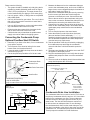
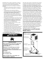
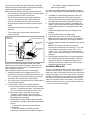
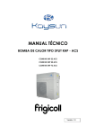
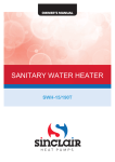
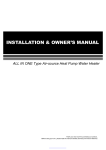
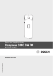
Hybrid Electric
Heat Pump Water Heater
Installation
Instructions and
Use & Care Guide
To obtain technical, warranty or service assistance during or after
the installation of this water heater, call toll free
1-800-527-1953
When calling for assistance, please have the following
information ready:
1. Model number
2. 10 Digit product number
3. Serial number
4. Date of installation
5. Place of Purchase
LOW LEAD
CONTENT
Table of Contents
Page
Water Heater Safety ............................................................................... 2
Installing Your Water Heater ................................................................. 3-9
Consumer Information ................................................................ 3
Consumer Responsibilities ......................................................... 3
Unpacking Instructions ............................................................ 3-4
Location Requirements ............................................................... 4
Water System Piping.................................................................5-6
Temperature & Pressure Relief Valve....................................... 7-8
Electrical Requirements............................................................ 8-9
Installation Checklist .............................................................................. 10
Operating Your Water Heater ........................................................... 11-14
Before Using ............................................................................. 11
Water Temperature Regulation ................................................. 11
Adjusting the User Interface Module/Operational Modes .......... 12
Operational Conditions ........................................................ 13-14
Maintenance of Your Water Heater .................................................. 15-16
Routine Maintenance................................................................. 15
Temperature and Pressure Relief Valve .................................... 15
Draining and Flushing........................................................... 15-16
Heating Element Replacement .................................................. 16
Diagnostic Codes .................................................................................. 17
Troubleshooting Chart ........................................................................... 18
Repair Parts Illustration ......................................................................... 19
326880-003
July, 2014
1
WATER HEATER SAFETY
Your safety and the safety of others are very important.
We have provided many important safety messages in this manual and on your appliance. Always read and obey all
safety messages.
This is the safety alert symbol.
This symbol alerts you to potential hazards that can kill or hurt you and others.
All safety messages will follow the safety alert symbol and either the word “DANGER” or
“WARNING.” These words mean:
You can be killed or seriously injured if you don’t
immediately follow instructions.
You can be killed or seriously injured if you don’t
follow instructions.
All safety messages will tell you what the potential hazard is, tell you how to reduce the chance of injury, and tell you
what can happen if the instructions are not followed.
Important Safety Instructions
CAUTION: Hydrogen gas is produced in a hot water system served by this heater that has not been used for a long
period of time (2 weeks or more). Hydrogen gas is extremely flammable. To reduce the risk of injury under these
conditions, it is recommended that the hot water faucet be opened for several minutes at the kitchen sink before
using any electrical appliance connected to the hot water system. When hydrogen is present, there will probably be
an unusual sound such as air escaping through the pipe as the water begins to flow. There should be no smoking or
open flame near the faucet at the time it is open.
The California Safe Drinking Water and Toxic Enforcement Act requires the Governor of California to publish a list of
substances known to the State of California to cause cancer, birth defects, or other reproductive harm, and requires
businesses to warn of potential exposure to such substances.
WARNING: This product contains a chemical known to the State of California to cause cancer, birth defects, or other
reproductive harm.
This appliance can cause low-level exposure to some of the substances included in the Act.
2
INSTALLING YOUR WATER HEATER
Consumer Information
This water heater should be installed in accordance with
the local code authority having jurisdiction, the power
company or electric utility, and this installation manual.
In the absence of local code requirements, follow the
regulations set forth in the latest edition of The National
Electric Code, NFPA 70. This is available from the
following:
National Fire Protection Association
1 Batterymarch Park
Quincy, MA 02269
American National Standards Institute
1430 Broadway
New York, NY 10018
Check your phone listings for the local authorities having
jurisdiction over your installation.
water heater functions like a standard electric water heater,
relying on the electric elements to heat the water. A Hybrid
Mode is available that relies primarily on the heat pump
to heat the water while the electric elements only function
during high demand periods. (See “Adjusting the User
Interface Module/ Operational Mode” section). The more
often the unit operates using the heat pump, rather than the
elements, the more efficient the unit will be.
The HPWH uses about half the electricity of a comparably
sized conventional electric water heater when operating
in the Efficiency/Hybrid Modes, and may provide up
to ½ ton cooling capacity and dehumidification. It is
designed for indoor, residential applications for installation
in a basement, garage or utility room (See “Location
Requirements” section).
Figure 1
Heat Pump Water Heater Basic Operation
Consumer Responsibilities
This manual has been prepared to acquaint you with the
installation, operation and maintenance of your electric heat
pump water heater and to provide important safety information
in these areas.
We urge you to read all of the instructions thoroughly before
attempting the installation or operation of this water heater.
This manual should be kept for future reference.
The manufacturer of this water heater will not be liable for any
damages caused by failure to comply with the installation and
operating instructions outlined in this manual.
If you lack the necessary skills required to properly install this
water heater or you have difficulty following the directions, you
should not proceed but have a qualified person perform the
installation of this water heater.
Examples of a qualified person include: licensed plumbers,
authorized electric company personnel, and authorized
service personnel.
Massachusetts code requires this water heater to be installed
in accordance with Massachusetts 248-CMR 2.00: State
Plumbing Code and 248-CMR 5.00.
A data plate identifying your water heater can be found
adjacent to the upper element door. When referring to your
water heater always have the information listed on the data
plate readily available, to include the model and serial number.
Retain your original receipt as proof of purchase.
Basic Operation Fundamentals
The Heat Pump Water Heater (HPWH) is an integrated
heat pump water heater unit, having a compressor and
external coil heat exchanger with backup electric elements
(Figure 1). When in Efficiency Mode, the heat pump draws
heat from the ambient air in the room and transfers it to
the water in the tank through the coil heat exchanger.
The backup element will turn on as a booster if the tank
temperature is too low from the set point during high
demand period, or if environmental conditions don't provide
enough heat to meet demand. While in Electric Mode the
Unpacking the Water Heater
WARNING
Excessive Weight Hazard
Use two or more people to move and install
water heater.
Failure to do so can result in back or
other injury.
Removing Packaging Materials
IMPORTANT: Do not remove, cover or deface any
permanent instructions, labels, or the data label from either
the outside of the water heater or on the inside of water
heater panels.
3
•
The water heater may be placed on it's designated side
(see carton) for local transportation only.
The water heater must be stored in an upright position.
Remove exterior packaging and place installation
components aside.
Inspect all parts for damage prior to installation and
start-up.
Completely read all instructions before attempting to
assemble and install this product.
After installation, dispose of/recycle all packaging
materials.
•
•
•
•
•
Location Requirements
Site location
Select a location near the center of the water piping system.
The unit must be installed indoors and in a vertical position
on a level surface. The flooring beneath the water heater
must be able to support the weight of the water heater when
filled with water (Table 1).
IMPORTANT: The water heater must have unrestricted
airflow and requires a minimum installation space of 700
cubic feet. As an example, a room that has an 8 foot tall
ceiling and is 10 feet long by 8-3/4 feet wide would contain
700 cubic feet.
NOTE: To ensure optimal performance and servicability, a
minimum clearance of 6 inches must be maintained from all
sides and 6 inches from the top for access to the air filter.
The water heater should be located in an area not subject
to freezing temperatures. Water heaters located in
unconditioned spaces (i.e., garages, basements, etc.) may
require the water piping, condensate piping, and drain piping
to be insulated to shelter against freezing. The drain and
controls must be easily accessible for operation and service.
The site location must be free from any corrosive elements in
the atmosphere such as sulfur, fluorine, sodium and chlorine.
These elements are found in aerosol sprays, detergents,
bleaches, cleaning solvents, air fresheners, paint, and
varnish removers, refrigerants, and many other commercial
and household products. In addition, excessive dust and
lint may affect the operation of the unit, see the Air Filter
Maintenance section in this manual.
The ambient air temperature must also be considered
when installing this unit. In Efficiency Mode the ambient
air temperature needs to be above 45°F/7.2 °C and below
120°F/48.8 °C for heat pump operation. If the ambient
air temperature falls outside these upper and lower limits
the electrical elements will activate to meet the hot water
demand and the heat pump does not operate in either
Efficiency Mode or Hybrid Mode.
NOTE: Local codes and requirements in your area may
require the installation of your water heater be accomplished
in a way that the bottom element is elevated from the
floor at least 18 inches. Ensure that a platform capable of
supporting the combined weight of the water heater and
water is used.
IMPORTANT: The water heater should be located in an
area where leakage of the tank, connections, condensate
lines or condensate will not result in damage to the area
adjacent to the water heater or to lower floors of the
structure. Due to the normal corrosive action of the water,
the tank will eventually leak after an extended period of
time. Also, any external plumbing leak, including those
from improper installation, may cause early failure of the
tank due to corrosion if not repaired. If the homeowner is
uncomfortable with making the repair a qualified person
should be contacted. A suitable metal drain pan should be
installed under the water heater as shown below, to help
protect the property from damage which may occur from
condensate formation or leaks in the piping connections
or tank. The pan must limit the water level to a maximum
depth of 2-1/2 inches and be two inches wider than the
heater and piped to an adequate drain. Locate the water
heater near a suitable indoor drain. Outside drains are
subject to freezing temperatures which can obstruct
the drain line. The piping should be at least 3/4” ID and
sloped for proper drainage. Under no circumstance will the
manufacturer or seller of this water heater be held liable
for any water damage which is caused by failure to follow
these instructions.
Figure 2
Metal Drain Pan
Installation
METAL
DRAIN
PAN
PIPED TO AN
ADEQUATE DRAIN
AT LEAST 2” GREATER THAN THE
DIAMETER OF THE WATER HEATER.
NOTE: The water heater shall be located so it is not subject
to physical damage by moving vehicles or area flooding.
Figure 3
Residential Garage
Installation
Vehicle
Stop
Drain
Pan
Table 1
4
Capacity
Filled Weight (lbs)
50 Gallon
573
66 Gallon
796
80 Gallon
921
Drain
State of California
NOTE: The water heater must be braced, anchored, or
strapped to avoid moving during an earthquake. Contact
local utilities for code requirements in your area, visit
http://www.dsa.dgs.ca.gov, or call 1-916-445-8100 and
request instructions.
Water System Piping
Piping, fittings, and valves should be installed according to
the installation drawing (Figure 4). If the indoor installation
area is subject to freezing temperatures, the water piping
must be properly insulated.
Water supply pressure should be 50-60 PSIG and not
exceed the maximum 80 PSIG. If the supply line pressure
exceeds 80 PSIG, a pressure reducing valve (PRV) with
a bypass should be installed in the cold water supply line.
This should be placed on the supply to the entire house in
order to maintain equal hot and cold water pressures.
IMPORTANT:
• Heat must not be applied to the water fittings on
the heater as they may contain nonmetallic parts. If
solder connections are used, solder the pipe to the
adapter before attaching the adapter to the hot and
cold water fittings.
• Always use a good grade of joint compound or Teflon®
tape and be certain that all fittings are tight.
IMPORTANT: DO NOT over apply joint compound.
Piping Installation
1. Install the water piping and fittings as shown in Figure
4. Connect the cold water supply (3/4” NPT) to the
fitting marked “Cold”. Connect the hot water supply
(3/4” NPT) to the fitting marked “Hot”.
2. The installation of unions in both the hot and cold
water supply lines are recommended for ease of
removing the water heater for service or replacement.
3. Some local codes may require, and the manufacturer
of this water heater recommends, installing a mixing
valve or an anti-scald device in the domestic hot water
line as shown in Figure 4. These valves reduce the
point-of-use temperature of the hot water by mixing
cold and hot water and are readily available. Contact
a licensed plumber or the local plumbing authority for
more information.
4. Some local codes may require, and the manufacturer
of this water heater recommends, installing a pressure
reducing valve (PRV) in the cold water inlet line where
it enters the residence as shown in Figure 4.
5. If installing the water heater in a closed water system,
install an expansion tank in the cold water line as
specified under “Closed System/Thermal Expansion.”
6. Install a shut off valve in the cold water inlet line. It
should be located close to the water heater and be
easily accessible. Know the location of this valve and
how to shut off the water to the heater.
7. Install a discharge line from the temperature and
pressure relief valve in the opening marked “T & P
RELIEF VALVE”. (see Figure 4 and the “Temperature
and Pressure Relief Valve” section.)
8. After piping has been properly connected to the water
heater, open the nearest hot water faucet. Then open
the cold water shut off valve and allow the tank to
completely fill with water. To purge the lines of any
excess air and sediment, keep the hot water faucet
open for 3 minutes after a constant flow of water is
obtained. Close the faucet and check all connections
for leaks.
Figure 4
Massachusetts: Install a vacuum relief in
cold water line per section 19 MGL 142.
Optional Heat Trap Piping
Vacuum Relief Valve
(when required by local code)
xxxx
x
xxxx
x
xxxx
x
xxxx
x
Union
Temperature and
Pressure Relief Valve
Union
Shut-off Valve (Hot)
1/2” Flexible
Secondary
Condensate
Tubing
Untempered Water Outlet
Hot
(Outlet)
Optional Mixing Valve - Follow the Mixing
Valve’s Manufacturer’s Installation
Instructions. (Set to 120°F / 48.8°C)
Tempered Water to Fixtures
Discharge Pipe
(Do Not Cap or Plug)
Cold Water
Inlet Valve
Cold Water
Inlet
Pressure Reducing Valve (PRV)
should be installed where the water
supply enters the residence.
When installed PRVs create a
closed water system, a thermal
expansion tank must be installed.
*Primary Condensate Drain (3/4” PVC)
Metal Drain Pan 2 1/2”
Depth Maximum and
2 Inches wider than
the water heater.
Cold
(Inlet)
In a closed system, use a
thermal expansion tank.
See “Closed System/
Thermal Expansion”
section.
Union
Shut-off Valve
(Cold)
Drain Line 3/4”
ID Minimum
Drain
6” Maximum
Air Gap
* If an adequate drain is not available for the condensate drain lines then a condensate pump must be used. DO NOT discharge the condensate drain
lines into the metal drain pan.
5
Please note the following:
• The system should be installed only with piping that is
suitable for potable (drinkable) water such as copper,
CPVC, PEX or polybutylene. This water heater must
not be installed using iron piping or PVC water piping.
• Use only pumps, valves, or fittings that are compatible
with potable water.
• Use only full flow ball or gate valves. The use of valves
that may cause excessive restriction to water flow is
not recommended.
• Use only 95/5 tin-antimony or other equivalent solder.
Any lead based solder must not be used.
• Piping that has been treated with chromates, boiler
seal, or other chemicals must not be used.
• Chemicals that may contaminate the potable water
supply must not be added to the piping system.
Connecting the Condensate Pump
Optional Overflow Shut Off Switch
1. Determine if you have a floor drain, if not a condensate
pump will be required.
2. Turn off power to the electrical wiring for the water
heater at the circuit breaker/fuse box.
3. Locate the white 18 AWG wire loop close to the drain
connections (Figure 5).
4. Cut the loop and strip insulation off of the two ends.
Figure 5
Condensate Pump Wiring
Condensate Drain
Access Cover
Main Drain Connection
5. Measure the distance from the condensate drain pan
cover to the condensate pump, and cut two 18 AWG or
larger wires to correct length and strip the insulation at
both ends of each wire (Figure 7).
6. Remove the condensate drain pan cover by removing
the four screws, pull these two wires through the
grommet on the drain pan cover. Connect these two
wires to the two wires on the water heater using wire
nuts or other connectors. Reinstall the drain pan cover
and keep the connection joint inside of the cover.
7. Connect the free ends of the two wires to the shut off
switch on the condensate pump in accordance with the
condensate pump manufacturers recommendations
(Figure 7).
8. Turn on electrical power to the water heater.
9. Select the efficiency mode. After about 8 minutes
(the user interface module will display “-”, “--”, “---”
repetitively during this period), the heat pump will turn
on if the ambient temperature and water temperature
meet the heat pump requirement.
10. Test the operation of the shut off switch by unplugging
the condensate pump and filling the condensate
reservoir with water until the float switch opens the
circuit.
11. The heat pump should turn off and the error code “EoF”
will appear on the display screen.
12. Plug the condensate pump in and verify that the pump
operates and pumps the water out of the condensate
reservoir.
13. The error code on the display should clear and the heat
pump should operate after 8 minutes.
Figure 7
Condensate Pump Wiring
Condensate Pump Wiring Loop
22 AWG - White
(Loop Located Close to the Drain Connections)
Overflow Slot
Condensate Pump Wiring
Loop 18 AWG-White
(Loop Located Close to the Drain Connections)
Wires to Condensate
Pump Overflow
Shut Off Switch
(22 AWG or Larger)
Figure 6
Wiring Diagram
Overload
Protection
Circuit
Breaker
Approved Connectors
Red
L1
Black
L2
To 240v
1 Phase
Power supply
Green
Ground
Wire
Electrical
Service ground
6
White Wires
From Water Heater
Condensate Drain Line Installation
The condensate drain lines consist of one 3/4" PVC line as
the primary condensate drain line and one 1/2" clear rubber
tubing for the condensate over flow. These condensate
lines are located on the upper right rear section of your
water heater. The lines should terminate a maximum of
six inches above an adequate drain. Do not discharge
the condensate drain lines into the metal drain pan. If no
floor drain is available or the drain is above the level of the
condensate line, a condensate pump should be installed.
These pumps are available from local distributors.
IMPORTANT: When making condensation connections
to the primary connection DO NOT over tighten. These
connections should be HAND TIGHTENED ONLY.
Overtightening could crack or damage the condensate
drain pan.
• Plastic pipe or tubing must be used to connect the
condensate drain to a suitable drain or condensate
pump.
• Condensate drain lines should be installed in
conditioned areas only. Install approved insulation on
the condensate drain lines to prevent condensation
from forming on the outside of the drain lines.
Condensation drain lines installed in areas that are
subject to freezing temperatures should be wrapped
with a nationally recognized/listed heat tape. Install per
manufacturer’s instructions.
• Do not connect condensate drain lines with other drain
or discharge lines into a single (common) pipe or line.
Each line (condensate drain line, temperature and
pressure relief valve discharge pipe, etc) should be
independently run to an adequate drain.
• Slope the condensate drain lines toward the inside
floor drain or condensate pump.
• The condensate drain lines and connections to the
drain piping must comply with all local codes.
• Use appropriate fittings, primer and glue to cement the
condensate drain lines to the heat pump drain pan.
• If a condensate pump is installed it should shut off the
heat pump in the event the condensate pump fails or
the float switch in the pump activates. (See section
on Condensate Pump Overflow Shut Off Switch in the
Electrical Requirements section.)
Closed System/Thermal Expansion
WARNING
Most public water systems in North America are required
to prevent water flowing from points of use (residences,
businesses, etc.) back into the supply system in order
to maintain water quality. To accomplish this, back flow
preventers such as check valves, are installed in the water
line going to each point of use. Typically the back flow
preventer will be installed at the water meter or inside a
building where the supply line enters the building. This
device allows water to flow into the residence but does
not allow it to flow back into the water supply. This creates
what is known as a “Closed System”. As water is heated
by the water heater, the water in the system attempts to
expand, but has nowhere to go resulting in an increase
in pressure. This increase in pressure in the system may
cause the temperature-pressure relief valve to open to
relieve the pressure. Water will drip from the temperature
and pressure relief valve. Premature tank failure will result
if this condition is not corrected. To prevent this condition, a
properly-sized thermal expansion tank should be installed
in the cold water supply to the water heater as shown in
Figure 4. Failure to install a properly sized expansion tank
in a closed system will void the warranty on the water
heater in the event of tank failure. It is important to follow
the thermal expansion tank manufacturers’ installation
instructions and to adjust the expansion tank pressure
to match the water supply pressure. Contact a plumbing
service agency or your retail supplier regarding the
installation of a thermal expansion tank.
Temperature and Pressure
Relief Valve
Figure 8
Temperature and Pressure
Relief Valve Installation
Temperature and
Pressure Relief Valve
Explosion Hazard
If the temperature and pressure relief valve
is dripping or leaking, have a qualified
person replace it.
Discharge Pipe
(Do Not Plug or Cap)
Examples of a qualified person include:
licensed plumbers, authorized electric
company personnel, and authorized service
personnel.
Drain Pan 2 1/2”
Depth Maximum and
2” wider than the
water heater
Do not plug valve.
Do not remove valve.
Failure to follow these instructions can
result in death or explosion.
Drain Line 3/4”
ID Minimum
Drain
6” Maximum
Air Gap
7
For protection against excessive pressures and
temperatures, a temperature and pressure relief valve must
be installed in the opening marked “T & P RELIEF VALVE”
(Figure 8).
To reduce the risk of excessive pressures and temperatures
in this water heater, install temperature and pressure relief
protective equipment required by local codes, but no less
than a combination temperature and pressure relief valve
certified by a nationally recognized testing laboratory that
maintains periodic inspection of the production of listed
equipment or materials, as meeting the requirements for
Relief Valves and Automatic Shutoff Devices for Hot Water
Supply Systems, ANSI Z21.22 - latest edition. This valve
must be marked with the maximum set pressure not to
exceed the marked maximum working pressure of the
water heater. Install the valve into an opening provided
and marked for this purpose in the water heater, and orient
it or provide tubing so that any discharge from the valve
exits only within 6 inches above drain, or at any distance
below, the structural floor, and does not contact any live
electrical part. The discharge opening must not be blocked
or reduced in size under any circumstance.
IMPORTANT: Only a new temperature and pressure relief
valve should be used with your water heater. Do not use an
old or existing valve as it may be damaged or not adequate
for the working pressure of the new water heater. Do not
place any valve between the relief valve and the tank.
The Temperature & Pressure Relief Valve:
• Shall not be in contact with any electrical part.
• Shall be connected to an adequate discharge line.
• Shall not be rated higher than the working pressure
shown on the data plate of the water heater.
The Discharge Line:
• Shall not be smaller than the pipe size of the relief
valve or have any reducing coupling installed in the
discharge line.
• Shall not be capped, blocked, plugged or contain
any valve between the relief valve and the end of the
discharge line.
• Shall terminate a maximum of six inches above a floor
drain or external to the building. In cold climates, it is
recommended that the discharge pipe be terminated at
an adequate drain inside the building.
• Shall be of material listed for hot water distribution.
• Shall be installed to allow complete drainage of both
the valve and discharge line.
Temperature/Pressure Relief Valve
Insulation
1. Locate the temperature and pressure relief valve on the
water heater, also known as a T&P relief valve (Figure
8).
2. Locate the slit running the length of the T&P relief valve
insulation.
8
3. Spread the slit open and fit the insulation over the T&P
relief valve (Figure 9). Apply gentle pressure to the insulation to ensure that it is fully seated on the T&P Relief
Valve. Once seated, secure the insulation with duct tape,
electrical tape, or equivalent.
IMPORTANT: The insulation and tape must not block
the discharge opening or hinder access to the manual
relief lever (Figure 9). Ensure a discharge pipe is installed into the T&P valve discharge opening per the
instructions in this manual.
Figure 9
T&P Relief Valve Insulation
T&P Relief Valve Insulation
Manual Relief Lever
T&P Relief Valve
T&P Relief Valve
Drain Line
Electrical Requirements
WARNING
Electric Shock Hazard
Disconnect power before
servicing.
Replace all parts and panels
before operating.
Failure to do so can result in
death or electrical shock.
WARNING
Fire Hazard
Use 10 gauge solid copper
wire.
Use a UL listed or
CSA approved strain relief.
Connect ground screw to
green ground wire.
Failure to do so can result in
death, fire, or electrical shock.
If you lack the necessary skills required to properly install the
electrical wiring to this water heater, do not proceed but have a
qualified electrician perform the installation.
When making the electrical connections, always make sure:
• The electrical service provides 240 VAC to the water heater
for proper operation. DO NOT use 208 VAC.
•
Wire sizes and connections comply with all applicable
codes or in the absence of local or state codes follow
NFPA-70, the National Electrical Code-current edition.
•
Wiring enclosed in approved conduit (if required by local
codes).
•
The water heater and electrical supply are properly
grounded.
•
The electrical supply has the proper overload fuse or
breaker protection.
Figure 10
Junction Box
Green
Ground
Wire
Black Wire
Green Ground Screw
1/2” Conduit
Opening
Power Supply
Connector
Red Wire
Always reference the wiring diagram located on the water
heater for the correct electrical connections and connect the
electrical supply to the water heater in accordance with local
utility requirements and codes.
When installing the electrical wiring to the water heater:
1. Although this water heater is equipped with “Dry Fire”
protection, be sure tank is completely filled with water, and
all air is purged from the tank before making any electrical
connections. See “Draining and Flushing Section”.
2. Turn off power to the electrical wiring for the water heater at
the circuit breaker/fuse box.
3. If metal conduit is used for the grounding conductor:
• The conduit or tubing is terminated in fittings
approved for grounding.
For complete grounding details and all allowable exceptions,
refer to the current edition of the National Electrical Code NFPA
70.
4. A standard 1/2" conduit opening has been made in the
water heater junction box for the conduit connections.
5. Use wire nuts and connect the power supply wiring to the
wires inside the water heater's junction box (Figure 10).
6. The water heater must be electrically "grounded" by the
installer. A green ground screw has been provided on the
water heater's junction box. Connect ground wire to this
location.
7. Replace the wiring junction box cover using the screw
provided.
8. Turn on electrical power to the water heater.
9. Press the Efficiency button to set the operating mode.
NOTE: The water heater will conduct a system diagnostic
(approximately 8 minutes) prior to returning to operation.
10. Once the diagnostic sequence has finished, the fan should
turn on.
NOTE: The heat pump’s fan will not turn on if the
incoming water temperature is less than 59°F / 15°C and/
or the ambient air temperature is above 120°F / 15°C
or below 45°F / 7.2°C. Should the internal diagnostics
detect a problem with the heat pump, an error code will be
displayed.
11. Set the desired operational mode. For typical installations,
the Hybrid Mode offers the best combination of efficiency
and hot water delivery. For detailed descriptions of all
operational modes see “Adjusting the User Interface
Module/Operational Modes” section.
Insulation Blankets
The use of an insulation blanket on this water heater is not
needed or recommended. The purpose of an insulation
blanket is to reduce the standby heat loss encountered with
storage tank heaters. Your water heater meets or exceeds
the National Appliance Energy Conservation Act standards
with respect to insulation and standby loss requirements,
making an insulation blanket unnecessary. If an insulation
blanket is installed, make sure it does not block airflow into
or out of the compressor assembly.
A. The grounding electrode conductor shall be of copper,
aluminum, or copperclad aluminum. The material shall
be of one continuous length without a splice or joint.
B. Rigid metal conduit, intermediate metal conduit,
or electrical, metallic tubing may be used for the
grounding means if conduit or tubing is terminated in
fittings approved for grounding.
C. Flexible metal conduit or flexible metallic tubing shall
be permitted for grounding if all the following conditions
are met:
• The length in any ground return path does not
exceed 6 feet.
• The circuit conductors contained therein are
protected by overcurrent devices rated at 30 amperes.
9
INSTALLATION CHECKLIST
Water Heater Location
Condensate Drain Line Installation
□
□
□
□
□
□
□
□
□
□
Centrally located with the water piping system.
The flooring beneath the water heater must be able to
support the weight of the water heater when filled with
water (Table 1).
Located indoors (such as a basement or garage)
and in a vertical position. Sheltered from freezing
temperatures.
Provisions made to shelter the area from water
damage. Metal drain pan installed and piped to an
adequate drain.
Sufficient room to service the water heater.
The water heater must have unrestricted airflow and
requires a minimum installation space of 700 cubic feet.
As an example, a room that has an eight foot tall ceiling
and is 10 feet long by 8-3/4 feet wide would contain
700 cubic feet.
NOTE: This Heat Pump Water Heater may be located
within a required minimum of 6” clearance from a
wall on the outlet side, however for future service
considerations a minimum clearance of 3 feet from
any obstruction on the back, left and right side is
recommended.
The unit cannot be placed into any type of closet or
small enclosure, unless adequate provision is made for
air exchange (vented or louvered doors, etc.).
The site location must be free from any corrosive
elements in the atmosphere such as sodium, sulfur,
fluorine, and chlorine. These elements are found
in aerosol sprays, detergents, bleaches, cleaning
solvents, air fresheners, paint, and varnish removers,
refrigerants, and many other commercial and
household products. In addition excessive dust and
lint may affect the operation of the unit and require
more frequent cleaning (See “Preventive Maintenance”
section).
Ambient air temperature should be above 45°F /
7.2°C and below 120°F / 48.8°C. If the ambient air
temperature falls outside these upper and lower limits
the electrical elements will activate to meet the hot
water demand.
□
Electrical Connections
□
□
□
□
□
□
□
□
□
10
Temperature and pressure relief valve properly
installed with a discharge pipe run to an adequate drain
and sheltered from freezing (Figure 8).
All piping properly installed and free of leaks.
Heater completely filled with water (See “Water Piping
System” section).
Closed system pressure buildup precautions installed
(See “Closed System/Thermal Expansion” section).
Mixing valve (when applicable) installed per
manufacturer’s instructions (See “Water Temperature
Regulation” section).
This water heater requires a 240 VAC single phase 30
amp power supply. DO NOT use a 208 VAC service.
Wiring size and connections comply with all applicable
codes or in the absence of local or state codes follow
NFPA-70, the National Electrical Code-current edition.
Water heater and electrical supply are properly
grounded.
Wiring enclosed in approved conduit (if required by
local codes).
Proper overload fuse or circuit breaker protection
installed.
Post Installation Review
□
□
Understand how to use the User Interface Module to
set the various modes and functions (See “Adjusting
the User Interface Module/Operating Modes” section).
Hybrid Mode is the recommended Operating Mode.
Understand the various Operating Modes and which
mode may be best, based on season, ambient
temperature, and usage (See “Operating Mode
Description” section).
Understand the importance of routine inspection/
maintenance of the condensate drain pan and lines
(See “Inspection/Cleaning of the Condensate Drain
Pan & Condensate Drain Lines” section). This is to
help prevent any possible drain line blockage resulting
in the condensate drain pan overflowing.
IMPORTANT: If water is coming from the overflowslot of the condensate drain pan cover (Figure 11) this
indicates that both condensation drain lines may be
Figure 11
Water System Piping
□
Must be located with access to an adequate drain or
condensate pump.
Condensate drain lines installed and piped to an
adequate drain or condensate pump (Figure 4).
Drain Pan Cover
Secondary Drain
Primary Drain
Overflow-Slot
□
□
blocked. Immediate action is required.
To maintain optimal operation, check, remove and
clean the air filter as needed (See “Air Filter Cleaning/
Replacement” section).
The Installation Instructions and Use & Care Guide
should be kept with the water heater for reference.
OPERATING YOUR WATER HEATER
Before Using
1. Make sure the water heater has been properly
installed. See “Installing Your Water Heater” section.
2. Make sure the air filter is correctly seated, as it may shift
during shipping or installation.
NOTICE: Make certain that there are no obstructions on
top of the unit that may block inlet or exaust air flow. See
“Repair Parts Illustration” section.
3. Completely fill the tank with water (See “Water Piping”
section).
4. After the water heater tank is completely filled with water,
connect electrical power to the water heater.
5. Read the “Water Temperature Regulation” section of this
manual. If you do not fully understand these instruction,
contact a qualified person.
6. When powered on, the unit will start to run a system
diagnostic. This typically takes eight minutes, (the user
interface module will display “-”, “--”, “---” repetitively
during this period). Once complete, proceed to the next
step.
NOTE: If the system diagnostic yields any codes,
reference the Diagnostic Code section in this manual.
7. Adjust the thermostat to the desired temperature
setting as described under “Adjusting the User Interface
Module/Operational Modes” section.
IMPORTANT: Do not attempt to operate this water heater
if the unit has been submerged, subjected to flooding, or
surrounding insulation has been exposed to water in any
way.
Do not attempt to repair a unit subjected to flood conditions.
Water heaters subjected to flood conditions or any time the
unit has been submerged in water require replacement of
the entire water heater.
Safety Shut-off (ECO)
This water heater is designed to automatically shut-off in the
event that the water temperature exceeds 190°F / 87.8°C.
A temperature limit switch or ECO (Energy Cut Off) is used
to shut off the power to the system if the water temperature
exceeds 190°F / 87.8°C (See “Water Temperature
Regulation” section). To reset the ECO disconnect power at
the circuit breaker/fuse box then remove the upper access
panel. Reset the ECO by firmly pushing in the red reset
button located on the ECO block. If the ECO continues
to shut-off the water heater, contact a qualified person for
service.
Water Temperature Regulation
WARNING
Water temperature over 125°F can cause
severe burns instantly or death from scalds.
Children, disabled and elderly are at highest
risk of being scalded.
Feel water before bathing or showering.
Temperature limiting valves are available.
The water heater is adjusted to a temperature setting of
no higher than 120°F / 48.8°C when it is shipped from the
factory. Water temperature can be regulated by adjusting
the User Interface Module to the preferred setting as shown
in “Adjusting the User Interface Module/Operational Mode”
The preferred starting point is 120°F / 48.8°C. There is a
hot water scald potential if the temperature set point is set
too high.
IMPORTANT: Adjusting the set point above 120°F / 48.8°C
on the User Interface Module will increase the risk of scald
injury in the times shown below.
Table 2
Water
Temperature
°F/°C
Time for 1st
Degree Burn
(Less Severe Burns)
Time for
Permanent Burns
2nd & 3rd Degree
(Most Severe Burns)
110°/43.3°
116°/46.6°
116°/46.6°
122°/50°
131°/55°
140°/60°
149°/65°
154°/67.7°
(normal shower temp.)
(pain threshold)
35 minutes
1 minute
5 seconds
2 seconds
1 second
instantaneous
45 minutes
5 minutes
25 seconds
5 seconds
2 seconds
1 seconds
(U.S. Government Memorandum, C.P.S.C., Peter L. Armstrong, Sept. 15,1978)
NOTE: During low demand periods when hot water is not
being used, a lower temperature set point will reduce energy
losses and may satisfy your normal hot water needs. If hot
water use is expected to be more than normal, a higher
temperature set point may be required to meet the increased
demand.
When leaving your home for extended periods (vacations,
etc.) set the water heater to Vacation Mode. See “Adjusting the
User Interface Module/Operational Modes” section. This will
maintain the water at low temperatures with minimum energy
losses and prevent the tank from freezing during cold weather.
NOTE: When returning from an extended stay remember to
set the water heater back to the desired Operational Mode. 11
Adjusting the User Interface Module/Operational Modes
Water Temperature Adjustment
◊
The water temperature can be adjusted from 95°F / 35°C to
140°F / 60°C. Use the Up and Down Buttons
on the front panel to set the desired temperature. The
setting temperature will blink on the display, press Mode/
Enter button to confirm.
The water temperature can be adjusted quickly by pressing
the “Temperature Up” button and holding for three seconds.
Hybrid Mode - This is the default, recommended
setting, combining high energy efficiency with
reduced recovery time. This mode uses the heat
pump as the primary heating source. The heating
element will heat water if demand exceeds a
predetermined level so that the set point temperature
can be recovered more quickly.
◊
Electric Mode - The water heater functions as
a conventional electric unit, relying on only the
elements for heat. This mode may be useful in winter
to eliminate the output of cold air from the unit.
IMPORTANT: Before attempting to adjust the thermostat,
read the “Water Temperature Regulation” section. If the
instructions are not clear, contact a qualified person.
IMPORTANT: For increased water demand, switching
(temporarily) to Hybrid Mode or Electric Mode will decrease
the recovery/re-heat time. Be sure to switch back to the
desired operational mode when finished.
Operating Mode Descriptions
The operating modes can be changed sequentially by
pressing the Mode/Enter button (Figure 12). The Operation
Mode Indication Light will turn on when the relevant mode
is selected.
This unit is equipped with technology that senses the
amount of water drawn from the unit. While in Efficiency or
Hybrid mode, during normal usage, the unit will operate the
heat pump for maximum efficiency. In times that the water
usage is above normal, this unit has the ability to use one
element (upper or lower) and the heat pump simultaneously
to help improve recovery. This transition is seamless and
will go unnoticed.
◊
12
Efficiency Mode - Provides the highest efficiency and
lowest cost operation by using only the heat pump for
heating. Recovery time and efficiency will vary with
ambient temperature and relative humidity. Efficiency
will be greatest, and recovery quickest, when both
are high. At lower temperatures and relative humidity
levels, efficiency will be lower and recovery will take
longer. Heat pump operation is allowed from 45°F /
7.2°C ambient temperature. At ambient temperatures
lower than 45°F / 7.2°C and greater than 120°F /
48.8°C, the heat pump will not operate. Similarly, if
the water temperature in the tank is less than 59°F
/ 15°C, the heat pump will not operate. The unit will
operate in electric mode until ambient and water
temperatures return to the safe operating range of the
heat pump.
◊
Vacation Mode - The controller adjusts the water
temperature to approximately 60°F. This mode
is recommended when the water heater is not in
use for a long period of time, to minimize energy
consumption and prevent the water heater from
freezing during cold conditions.
NOTE: When Vacation Mode is selected, the
vacation timer will be displayed. Press the Up and
Down button to modify the timer to desired number
of vacation days (setting range: 1 to 99 days). The
vacation timer will blink on the display; press the
Mode/Enter button to confirm the vacation timer. To
deactivate Vacation Mode, press the Mode/Enter
button to switch to the desired mode.
IMPORTANT: Do not shut off power to the unit for
extended periods of time. If power must be turned
off for an extended period of time, drain the tank
completely.
CAUTION: Hydrogen gas is produced in a hot water
system served by a water heater that has not been used
for a long period of time (2 weeks or more). Hydrogen
gas is extremely flammable. To reduce the risk of injury
under these conditions, it is recommended that the hot
water faucet be opened for several minutes at the kitchen
sink before using any electrical appliance connected to
the hot water system. When hydrogen is present, there
will probably be an unusual sound such as air escaping
through the pipe as the water begins to flow. There
should be no smoking or open flame near the faucet at
the time it is open.
Other Controls
°F/°C
°F/°C Switch - Press “Temperature Down” button
and hold for 3 seconds to switch temperature unit
between Farenheit and Celsius
Power Saver Enable/Disable - Press “Mode/Enter” button
and hold for 3 seconds. The power saver feature will be
activated and the display will show “P.S.”, and the setting
temperature alternatively. This feature allows the unit to be
managed by grid or other utility based load management
programs.
To deactivate the power saver, press “Mode/Enter” button
and hold for 3 seconds.
Heat pump defrosting indication - There will be frost accumulating on the evaporator when the heat pump is operated under low ambient temperatures. The controller will
order the unit to enter into defrosting cycle to optimize the
heat pump operation performance. During the defrosting
period, the user interface module will display “ICE” as an
indication.
Out of heat pump operation range - The user interface
module will display “HPO” as an indication that the ambient
and/or water temperature condition is out of the heat pump
operation range.
Figure 12
Operational Conditions
Water Odor
In each water heater there is installed at least one anode
rod (see parts sections) for corrosion protection of the tank.
Certain water conditions will cause a reaction with this rod
and the water. The most common complaint associated
with the anode rod is one of a "rotton egg smell" in the
hot water. This odor is derived from hydrogen sulfide gas
disolved in the water. The smell is the result of four factors
which must all be present for the odor to develop:
A. A concentration of sulfate in the supply water.
B. Little or no dissolved oxygen in the water.
C. A sulfate reducing bacteria which has accumulated
within the water heater (this harmless bacteria is nontoxic
to humans).
D. An excess of active hydrogen in the tank. This is caused
by the corrosion protective action of the anode.
Smelly water may be eliminated or reduced in some
water heater models by replacing the anode(s) with one
of less active material, and then chlorinating the water
heater tank and all hot water lines. Contact the local water
heater supplier or service agency for further information
concerning an Anode Replacement Kit and the chlorination
treatment. If the smelly water persists after the anode
replacement and chlorination treatment, we recommend
that chlorination or aeriation of the water supply be
considered to eliminate the water problem.
Water Heater Sounds
During the normal operation of the water heater, sounds or
noises may be heard. These noises are common and may
result from the following:
NOTE: The display will go into “Sleep Mode” for energy
saving if there is no operation on any button for 15 minutes. All the display and light will be turned off except for
the “Opertional Mode Indication Light”, which will be on
all the time when the unit is powered on. The unit will be
awakened by pressing any button.
1. Normal expansion and contraction of metal parts
during periods of heat-up and cool-down.
2. Sediment buildup on or around the elements could
create varying amounts of noise and may cause
premature tank failure. Drain and flush the tank as
directed under the “Draining and Flushing” section.
3. The heat pump compressor or fan running.
Stacking
Stacking occurs when a series of short hot water draws (3
gallons or less) are made. This causes increased cycling
of the heat pump and/or heater elements and can result in
increased water temperatures at the hot water outlet. An
anti-scald device is recommended in the hot water supply
line to reduce the risk of scald injury.
13
Do not remove the anode leaving the tank unprotected.
By doing so, all warranty on the water heater tank is
voided.
ANODE ROD INSPECTION
tAvoid water heater damage
tInspection and replacement of anode rod recommended
"AIR" IN HOT WATER FAUCETS
HYDROGEN GAS: Hydrogen gas can be produced in
a hot water system that has not been used for a long
period of time (generally two weeks or more). Hydrogen
gas is extremely flammable and explosive. To prevent the
possibility of injury under these conditions, we recommend
the hot water faucet, located farthest away, be opened for
several minutes before any electrical appliances which
are connected to the hot water system are used (such
as a dishwasher or washing machine). If hydrogen gas is
present, there will probably be an unusual sound similar
to air escaping through the pipe as the hot water faucet is
opened. There must be no smoking or open flame near the
faucet at the time it is open.
HIGH WATER TEMPERATURE SHUT OFF SYSTEM
A non-adjustable high temperature limit control operates
before steam temperatures are reached. The high limit is in
the same area as the upper thermostat and must be reset
manually when it operates. BECAUSE THE HIGH LIMIT
OPERATES ONLY WHEN ABNORMALLY HIGH WATER
TEMPERATURES ARE PRESENT, IT IS IMPORTANT
THAT A QUALIFIED SERVICE AGENT BE CONTACTED
TO DETERMINE THE REASON FOR OPERATION
BEFORE RESETTING.
•
•
•
•
•
•
•
14
Turn off the heater electrical supply. Do not attempt to
reset thermostat with power on.
Remove the screw securing the outer door and remove
door.
Fold up the insulation to expose the reset button.
Reset the high limit by pushing the red button marked
"reset".
Replace the insulation so that it completely covers the
thermostat and element.
Replace the outer door.
Turn "ON" electric power to the water heater.
Each water heater contains at least one anode rod, which
will slowly deplete (due to electrolysis) prolonging the life
of the water heater by protecting the glass lined tank from
corrosion. Adverse water quality, hotter water temperatures, high hot water usage, hydronic heating devices and
water softening methods can increase the rate of anode
rod depletion. Once the anode rod is depleted, the tank
will start to corrode, eventually developing a leak.
Certain water conditions will cause a reaction between the
anode rod and the water. The most common complaint
associated with the anode rod is a "rotten egg smell" produced from the presence of hydrogen sulfide gas dissolved
in the water. IMPORTANT: Do not remove the anode rod
permanently as it will void any warranties. A special anode
rod may be available if water odor or discoloration occurs.
NOTE: This anode rod may reduce but not eliminate water
odor problems. The water supply system may require special filtration equipment from a water conditioning company
to sucessfully eliminate all water odor problems.
Artificially softened water is exceedingly corrosive because
the process substitutes sodium ions for magnesium and
calcium ions. The use of a water softener may decrease
the life of the water heater tank.
The anode rod should be inspected after a maximun of
three years and annually thereafter until the condition of
the anode rod dictates its replacement. NOTE: Atrificially
softened water requires the anode rod to be inspected
annually.
The following are typical (but not all) signs of a depleted
anode rod (Figure 13):
• The majority of the diameter is less than 3/8".
• Significant sections of the support wire (approx, 1/3 or
more of the anode rod's length) are visible.
If the anode rod shows signs of either or both it should be
replaced.
NOTE: Whether re-installing or replac- Figure 13:
ing the anode rod, check for any leaks
and immediately correct if found.
In replacing the anode:
1. Turn off power to the water heater.
2. Shut off the water supply and open
a nearby hot water faucet to depressurize the water tank.
3. Drain approximately 5 gallons
of water from the tank. (Refer to
"Draining and Flushing" for proper
procedures). Close drain valve.
4. Remove old anode rod.
5. Use Teflon® tape or approved pipe
sealant on threads and install new
anode rod.
6. Turn on water supply and open a nearby hot water
faucet to purge air from water system. Check for any
leaks and immediately correct any if found.
7. Restart the water heater as directed in this manual.
See the repair part illustration for anode rod location.
MAINTENANCE OF YOUR WATER HEATER
Routine Maintenance
Routine visual inspections should be made of the following:
• Remove and inspect the air filter, clean if needed, and
reinstall - quarterly.
• Condensate drain pan and condensate lines - annually.
• The lower metal drain pan for standing water which may
indicate a clogged condensate drain pan, condensate
lines, or plumbing leak - annually.
• Leaking or damaged water piping - annually.
• Presence of corrosive materials in the installation area annually.
• Presence of combustible materials near the water heater
- annually.
• After servicing this water heater, check to make sure it
is working properly. (See “Operating Your Water Heater”
section of this manual.)
IMPORTANT: If you lack the necessary skills required to
properly perform this visual inspection, you should not
proceed, but get help from a qualified person.
Air Filter Maintenance
The heater will monitor the heat pump operation status
and indicate whether the filter should be cleaned. If the
User Interface Module displays “SF” code, this indicates
the filter should be cleaned or replaced with the following
process (See exploded view of unit on last page for air filter
location).
IMPORTANT: Before attempting to clean or replace the
air filter, turn-off power to the water heater at the circuit
breaker/fuse box.
1. Take the two tabs on the air filter and remove (slide) it
from the top cover of the unit.
2. If you are replacing the filter skip to step 4. To clean the
filter use a vacuum with a hose attachment to remove
any dust or debris.
3. Place the new or cleaned filter into the water heater.
4. Restore power to the water heater and turn the water
heater on. NOTE: the water heater will conduct a
system diagnostic prior to operation.
Condensate Drain Maintenance
IMPORTANT: Before attempting to clean or replace the
condensate drain pan or lines, shut-off power to the water
heater at the circuit breaker/fuse box.
1. Remove the top jacket by loosening the screws securing
it to the unit.
2. Check the condensate drain pan and drain lines for any
dirt or debris that might interfere with proper drainage.
Wipe out any dirt or debris with a damp cloth.
3. Once the condensate drain pan and lines have been
inspected/cleaned, secure the top jacket to the water
heater.
4. Restore power to the water heater and turn the water
heater on.
NOTE: The water heater will conduct a system diagnostic
prior to operation.
Temperature and Pressure
Relief Valve
WARNING
Explosion Hazard
If the temperature and pressure relief valve
is dripping or leaking, have a qualified
person replace it.
Examples of a qualified person include:
licensed plumbers, authorized electric
company personnel, and authorized service
personnel.
Do not plug valve.
Do not remove valve.
Failure to follow these instructions can
result in death or explosion.
Manually operate the temperature and pressure relief valve
once a year to make sure it is working properly (Figure 14).
To prevent water
Figure 14
damage, the valve
Temperature and Pressure
must be properly
Relief Valve
connected to a
Manual Relief
discharge line which
Valve
terminates at an
adequate drain.
Standing clear of the
outlet (discharged
water may be
hot), slowly lift and
release the lever
Discharge line to drain
handle on the
temperature and
pressure relief valve to allow the valve to operate freely and
return to its closed position. If the valve fails to completely
reset and continues to release water, immediately
disconnect the electrical power, close the cold water inlet
valve and call a qualified person.
15
Draining and Flushing
It is recommended that the tank be drained and flushed
every 6 months to remove sediment which may build up
during operation. The water heater should be drained if
being shut down during freezing temperatures. To drain the
tank, perform the following steps:
1. Turn off the power to the water heater at the circuit
breaker/fuse box.
2. Open a nearby hot water faucet until the water is no
longer hot.
3. Close the cold water inlet valve.
4. Connect a hose to the drain valve and terminate it to an
adequate drain or external to the building.
5. Open the water heater drain valve and allow all of the
water to drain from the tank. Flush the tank with water
as needed to remove sediment.
6. Close the drain valve, refill the tank (open the cold
water inlet valve), and restart the heater as directed in
this manual.
IMPORTANT: Do not turn on power to the water heater
unless it is completely filled with water. To ensure that
the tank is full, open a hot water faucet and allow the
water to run until the air is purged and the water flows
uninterrupted from the faucet.
NOTE: The water heater will conduct a system
diagnostic prior to operation.
If the water heater is going to be shut down for an extended
period, the drain valve should be left open.
Heating Element Replacement
WARNING
3. Remove the access cover(s), then take off the white
fiber dam.
4. Remove the protective plastic cover(s) over the
elements from their attachment point.
5. Disconnect the electrical wires from the heating
element(s) by loosening the screws (Figure 15).
Remove the screw-in element(s) by turning the
element(s) counterclockwise with a 1-1/2 inch socket
wrench. Remove the existing gasket(s)
Figure 15
Wires
Element
Screws
6. Clean the area where the gasket(s) fits to the tank
and internal threads. If you are replacing the bottom
element, remove any accumulated sediment on the
bottom of the tank.
7. Make sure the replacement element(s) has the correct
voltage and wattage rating by matching it to the rating
plate on the water heater. Position the new gasket(s)
on the element and insert it into the water heater tank
(Figure 16).
Figure 16
Screw-in
Element
Spud
Electric Shock Hazard
Disconnect power before
servicing.
Gasket
Replace all parts and panels
before operating.
Failure to do so can result in
death or electrical shock.
Replacement heating elements must be of the same style
and voltage/wattage rating as the ones originally in the water
heater. This information can be found on the flange or terminal
block of the element or on the water heater data plate.
8.
9.
10.
IMPORTANT: Before replacing any element, confirm that
you have the correct replacement element (wattage). This
water heater has a 4500 watt upper element and a 4500
watt lower element. DO NOT replace the element(s) with a
wattage different than the ones specified for the upper and/
or lower element.
11.
IMPORTANT: Using an element greater than 4500 watts
will damage the water heater and void the warranty.
1. Turn off the power to the water heater.
2. Drain the water heater as directed in the “Draining
and Flushing” section.
14.
16
12.
13.
15.
NOTE: Apply a light coat of hand dishwashing soap
and water to the gasket. Tighten the element by turning
it clockwise until secure.
Close the drain valve and open the nearest hot water
faucet. Then open the cold water shut off valve and
allow the tank to fill completely with water. To purge
the lines of any excess air and sediment, keep the hot
water faucet open for 3 minutes after a constant flow of
water is obtained.
Check for leaks around the element(s).
Reconnect the electrical wires to the element and
securely tighten the screws (Figure 15).
Replace the protective plastic cover(s) removed earlier.
Make sure the cover(s) are securely engaged on the
attachment point(s).
Replace the white fiber dam and access cover(s).
Although this water heater is equipped with “Dry Fire”
protection circuitry, be sure tank is completely filled with
water before applying electrical power to the water heater.
Reconnect electrical power to the water heater at the
circuit breaker/fuse box.
Set the desired water temperature and operating mode.
NOTE: The water heater will conduct a system
diagnostic (approximately 8 minutes) prior to operation.
DIAGNOSTIC CODES
DISPLAY SHOWS
EUC
INDICATES
Upper element is not functioning
CORRECTIVE ACTION
1.
2.
ELC
Lower element is not functioning
1.
2.
Turn off power at the circuit breaker/fuse box and check for
a loose connection at the element. For access directions
see “Heating Element Replacement” section. If error persists
proceed to the next step.
Replace non-functioning element. See “Heating Element
Replacement” section.
Turn off power at the circuit breaker/fuse box and check for
a loose connection at the element. For access directions
see “Heating Element Replacement” section. If error persists
proceed to the next step.
Replace non-functioning element. See “Heating Element
Replacement” section.
SF
The air filter is dirty.
1.
2.
Turn off power at the circuit breaker/fuse box.
Clean the air filter. See “Air Filter Cleaning/Replacement”
section.
ECF
The heat pump compressor is
starting/stopping frequently.
1.
2.
Turn off power at the circuit breaker/fuse box.
Clean the air filter. See “Air Filter Cleaning/Replacement”
section.
If error persist, please contact a qualified person to check the
fan wire connection.
3.
E20 or E21
Upper Temperature Sensor is not
functioning.
E30 or E31
Lower Temperature Sensor is not
functioning.
E50 or E51
Heat Pump Suction Temperature
Sensor is not functioning.
E10 or E11
Heat Pump Coil Temperature
Sensor is not functioning.
E40 or E41
Heat Pump Discharge
Temperature Sensor is not
functioning.
Edr
Not enough water in the tank
(tank not full).
Fill completely-Open all hot water taps in home and run until water
(uninterupted) flows from all open hot water taps.
EPL
Power supply voltage is too low.
Check the power supply to the unit and make sure it is higher than
204V
EDH
Heat Pump Discharge
Temperature is too high.
Contact a qualified technician to service the unit.
EoF
(If Accessory Condensate
Pump is installed)
Condensate pump failure.
1.
Contact a qualified person to service the unit.
2.
3.
4.
ECL
Heat pump suction pressure is
too low.
EEE
EEPROM failure
ECC
Heat pump compressor is not
functioning.
“-”,”--”,”---”
Unit is doing a system diagnostic.
ICE
Heat pump is in defrosting cycle.
HPO
Heat pump is out of operation
envelope.
Check to see if accessory condensate pump is plugged in and
has power. Also check circuit breaker/fuse box and GFCI (if
used). If error persists, proceed to the next step.
Check condensate pump outlet tube for blockage. If error
persists, proceed to the next step.
Check control wire connections to condensate pump. If error
persists, proceed to the next step.
Replace accessory condensate pump. If error persists, contact
a qualified technician to service the unit.
Contact a qualified technician to service the unit
No action is necessary.
NOTE: The diagnostic codes listed above are the most common. If a diagnostic code not listed above is displayed,
contact Residential Technical Assistance referencing the number on the front of this manual.
17
TROUBLESHOOTING CHART
PROBLEM
NO HOT WATER
POSSIBLE CAUSE(S)
1.
No power to the water heater (No
lights on the unit are on).
1.
Check for blown fuse or tripped breaker.
Restore power to unit.
2.
Unit in Vacation mode
2.
3.
High temperature limit switch open
3.
4.
Hot water usage pattern exceeds the
capability of the water heater in
current mode
Non-functioning upper temperature
sensor
4.
Press Mode/Enter button and return to desired
operating mode.
Reset the high temperature limit switch; see
“Safety shut-off” section for more information.
Change to different mode or modify usage patterns.
5.
Contact a qualified person for service.
1.
Temperature set-point too low
1.
2.
3.
Air filter dirty
Hot water usage pattern exceeds the
capability of the water heater in
current mode
Water connections to unit reversed
2.
3.
5.
6.
7.
8.
Heat lost through long run of exposed
pipe
Hot water leak at faucet or piping
Non-functioning heating element
Sediment or scale build up in tank
Increase set point temperature; see “Adjusting
the User Interface Module” section
Clean air filter
Change to different mode or modify usage
patterns (For example if in Efficiency Mode
switch to Hybrid Mode)
Ensure the cold connection is at the bottom
and that the hot connection is at the top
Insulate exposed piping
6.
7.
8.
Repair hot water leaks
Call qualified person for service
Drain and flush tank. Water conditioning may
be necessary to minimize build up
1.
Temperature set-point too high
1.
2.
3.
Air filter dirty
Electric mode selected
2.
3.
4.
Water connections to unit reversed
4.
5.
5.
6.
7.
Heat lost thru long run of exposed
pipe
Hot water leak at faucet or piping
Sediment or scale build up in tank
Decrease set point temperature; see “Adjusting
the User Interface Module”
Clean air filter
Change to Efficiency or Hybrid mode for reduced energy costs
Ensure the cold connection is at the bottom
and that the hot connection is at the top
Insulate exposed piping
6.
7.
Repair hot water leaks
Drain and flush tank. Water conditioning may
be required to minimze build up
1.
Excessive water pressure
1.
2.
Add or service a thermal expansion
tank.
Non-functioning Temperature &
Pressure Relief Valve
2.
Check water supply inlet pressure. If higher than
80 PSIG, install a pressure reducing valve (5060 PSIG is the recommended pressure.)
See “Closed System/Thermal Expansion” section
3.
Replace the Temperature & PressureRelief
Valve
The water heater does not
immediately start
The heat pump does not run in
Efficiency mode.
1.
When first started the water heater takes about 8
minutes to complete a diagnostic routine
Contact a qualified person for service
5.
INSUFFICIENT HOT WATER/
SLOW HOT WATER
RECOVERY
4.
5.
HIGH OPERATION COSTS
DRIP FROM TEMPERATURE &
PRESSURE RELIEF VALVE
(Warning: Do not plug or cap
T&P discharge pipe.)
3.
OTHER
1.
2.
18
CORRECTIVE ACTION
4.
2.
REPAIR PART ILLUSTRATION
REPAIR PARTS LIST
PARTS DESCRIPTION
ITEM
NO.
Figure 17
8
16
15
9
7
14
6
19
3
11
4
1
5
2
11
2
1
10
1
Element Access Cover
2
Element (4500 Watts)
3
Energy Cut-Off (ECO) Switch
4
Temperature & Pressure Relief Valve (T&P)
5
Dip Tube (at hot water outlet)
6
Anode
7
Controller
8
Air Filter
9
Fan Assembly
10
Drain Valve
11
Element Terminal Cover
12
Ambient / Coil / Discharge Temperature Sensor*
13
Upper / Lower Tank Temperature Sensor*
14
Fan Shroud
15
Condensate Drain Connection Cover
16
Electronic Expansion Valve Coil
17
Start Capacitor*
18
Relay Kit*
19
Condensate Drain Pan
* NOT SHOWN
REPAIR PARTS
Repair parts may be ordered through your plumber, local
distributor, home improvement center, or by calling
1-800-527-1953. When ordering repair parts always give
the following information:
1. Model, serial and product number
2. Item number
3. Parts description
19
500 Tennessee Waltz Parkway, Ashland City, TN 37015
Technical Support: 800-527-1953 • Parts: 800-433-2545 • Fax: 800-644-9306
www.hotwater.com
Copyright © 2014, Inc. All Rights Reserved
20