1
Basic Course for BN-20
Table of Contents
Introduction……………………………………………………………………………… 1
Functions and Applications for BN-20… …………………………………………… 1
1. Output Data Preparation
Creating Output Data… ……………………………………………………………… 2
Creating Cutting Data… ……………………………………………………………… 5
Metallic Silver Graphic Data Creation… …………………………………………… 6
1)Metallic Silver ……………………………………………………………………… 7
2)Original Metallic Color (Silver & CMYK colors)… ……………………………… 8
3)Metallic Color System Library (512 colors)……………………………………… 9
4)Metallic Texture System Library (26 patterns)… …………………………… 12
5)Metallic Silver Gradation… …………………………………………………… 15
2. Printing from Application
Output data from Illustrator to Roland VersaWorks……………………………… 19
A: Output data Using a Printer Driver (PS Driver)… …………………………… 20
B: Output data Creating an EPS File from Illustrator… ………………………… 22
When outputting an Image Data with Illustrator 10 or later… ………………… 24
3. Roland VersaWorks Settings
Basics of Roland VersaWorks……………………………………………………… 26
Job Settings and Printing…………………………………………………………… 29
Coutour Cutting after Lamination… ……………………………………………… 34
4. BN-20's Utility
How to Open the Utility Window…………………………………………………… 37
Confirmation of Ink levels…………………………………………………………… 37
Checking Amount of Waste Fluid… ……………………………………………… 38
Checking Nozzle Conditions / Cleaning Method………………………………… 39
Bidirectional Adjustment… ………………………………………………………… 40
Feed Calibration… ………………………………………………………………… 41
Adjusting Cutting… ………………………………………………………………… 42
Adjusting Printing & Cutting………………………………………………………… 43
Crop Cut Adjustment………………………………………………………………… 44
5.User Maintenance
Manual Cleaning… ………………………………………………………………… 45
6.Ink and Media
ECO-SOL MAX INK Usage Conditions…………………………………………… 48
Media… ……………………………………………………………………………… 48
ECO-SOL MAX INK and Media… ………………………………………………… 49
ECO-SOL MAX INK Characteristics (Vinyl Media)… …………………………… 49
Measures Against Warping and Shrinkage… …………………………………… 50
Introduction
This training guide has been compiled to help you to understand the series of steps required to print with
VersaSTUDIO BN-20. Metallic silver graphic data creation, output settings and printing methods are mainly
explained.
All Explanations on the guide use VersaSTUDIO BN-20 (including Utility) and Adobe® Illustrator except
R-Works.
Functions and Applications for BN-20
The BN-20 is compact and new concept printer including three functions; printing only, cutting only, and printing
and cutting, which is especially suited for SOHO print business
Inaddition, you can easily create premium value decals
and posters with Metallic silver ink.
◆ Metallic Silver Ink
Metallic Silver Ink is a special ink which includes silver color material for inkjet printer.
With the addition of Metallic Silver Ink, The BN-20 allows you to express brilliant metallic silver colors and easily
print a variety of metallic colors - gold, bronze, titanuim black, metallic blue and metallic green - combining with
CYMK process color.
The Metallic Silver Ink is an epoch-making ink which can open a new world of createvie expression.
◆ Print and Cut Funtion
The Print-Cut function is an unique and convenient solution of Roland, it combines the printing and cutting
function into a single piece of equipment. After printing, the media is repositioned and cut in the same location.
The printing and cutting can be performed without having to remove the media which greatly reduce the
operation time compared to conventional label printing processes.
VersaSTUDIO
Compare
workflow : Roland (VersaCAMM) vs. conventional label printer
BN-20
1
1
Output Data Preparation
Creating Output Data
In case of output from Adobe® Illustrator®, you can use a RIP and print management software "Roland
VersaWorks" included with the product. It makes it possible to process both RGB and CMYK data.
When designing bitmap, text or vector graphics, you can gain desirable output results by taking note of the
following points.
The explanations are based on Illustrator here below.
1) Color mode in Illustrator
Make sure that you set the Illustrator color mode as [CMYK Color].
Bitmap data should be created using [RGB Color] and text and vector data should be created using [CMYK
Color]. However, data that has already been converted to the CMYK color format will be handled as such.
Illustrator data
RGB
RIP
BN-20
CMYK
CMYK
RGB image data
CMYK text data
2) Outline text data
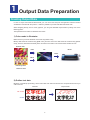
Because of PostScript processing, all the texts other than PS fonts will become corrupted. Ensure that you
outline the text.
Illustrator
Output Result
Non outline
Outline
2
3) What is an Appropriate Resolution for the Image Data?
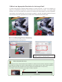
For large format printing, the desired image resolution is 150 PPI at full size. In case of low resolution, its
image is an unsuitable for viewing from a short distance since the pixel is too coarse. If an original image
resolution is low, the print quality will not improve by increasing the image resolution set with an application.
The resolution of the original image must be as high as possible. If scanning, the highest resolution should be
used and then saved to an appropriate lower resolution after all adjustments have been made.
150ppi
50ppi
How to confirm [Image Size] in Photoshop
Select [Image Size] on the [Image] menu.
Document size: 68.58 mm x 68.58 mm
Resolution: 150 PPI. File size: 454.4K
$'9,&(
What is PPI (Pixels Per Inch)?
PPI (pixels per inch) is a measurement of the resolution on devices such as monitors. Squares are aligned
horizontally and vertically, and each of these displays a color, shade and tone. Each of these squares is
called a pixel and the PPI unit refers to how many pixels are contained within 1 inch (2.54 cm).
For example, 100 PPI means that 1 inch long line contains 100 pixels.
1pixel
1inch=2.54cm
3
4)Important Points when Placing (Linking or Embedding) an Image Data
Adobe Illustrator version 9 and later allows you to select the color mode for the document as an output setting
for the artwork. You can select the color mode, [RGB] or [CMYK] when creating a new file.
This feature can cause differences in the output when placing an EPS file by linking or embedding.
For example, when the document color mode is set to CMYK, embedding an RGB image causes the image to
be converted to CMYK, changing the color of the image data.
For applications such as signs and banners where the saturation is important, it is recommended to link the
image data when placing an RGB image in Illustrator.
Placing RGB image with EPS format in a CMYK document (link or embed)
<Embed>
<Link>
<Simulated Output: Link>
<Simulated Output: Embed>
RGB data
Converted from RGB data to CMYK data
4
Creating Cutting Data
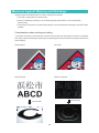
You can easily configure the color of cutline (path) to the spot color named "CutContour"in application software
(Illustrator, etc,.) and then the "Cutcontour" is recognized as the cutting line.
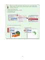
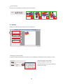
1.Open "Swatch Libraries" for spot color.
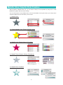
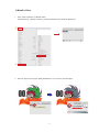
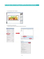
Select [Window] ‒ [Swatch Libraries] ‒ [Roland VersaWorks] from Illustrator [Menu] bar.
①
Change the view to [Small List View]
③
・CutContour …………. Cutline
・RDG_WHITE……….. White Ink
・RDG_GLOSS………. Gloss Ink
・RDG_MetallicSilver… Metallic Silver
②
2.Change the line to [CutCoutour] after selecting an object you would like to cut.
5
Metallic Silver Graphic Data Creation
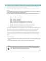
With the addtion of Metallic Silver Ink, you can create a variety of color expression by using how to create
Metallic silver graphic data and output settings.
You can easily output not only Metallic silver color but also Metallic Color System Library (512 colors) which
combines metallic silver ink with CMYK process colors.
1) Metallic Silver
2) Original Metallic Color (Silver & CMYK Colors)
3) Metallic Color System Library (512 colors)
30
-0
-0
nt
nt
ra
ra
M
TVib
L-
ra
M
TVib
LRT
S
M
TVib
L-
ra
nt
nt
-0
-0
30
30
RT
S
LRT
S
RT
S
RT
S
L-
M
TVib
ra
an
nt
t-0
-0
30
30
RT
S
L-
M
TVib
M
TVib
ra
an
nt
t-0
-0
30
30
30
4) Metallic Texture System Library (26 patterns)
5) Metallic Silver Gradation
6
1) Metallic Silver
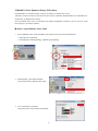
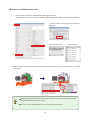
1.Open "Swatch Libraries" for Metallic Silver.
Select [Window] ‒ [Swatch Libraries] ‒ [Roland VersaWorks] from Illustrator [Menu] bar.
①
③
②
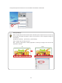
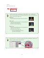
2.Select an object and configure “RDG_MetallicSIlver” to it in order to paint the object.
7
2)Original Metallic Color (Silver & CMYK colors)
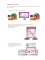
When "CMYK (process) colors" and “RDG_MetallicSilver” are overlapped, you can create an original metallic
color by by mixing the two colors.
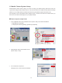
1.Select an object you would like to edit.
① Click [Edit] ‒ [Copy].
② Then click [Edit]-[Paste in Front] to copy it to the Forehead.
①
②
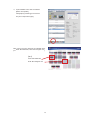
2.While selecting the copied object pasted in front, specify [RDG_MetallicSilver] to paint the object.
【Graphic Data Completed】
Green object and [RDG_MetallicSilver] object
are overlapped.
8
3) Metallic Color System Library 512 colors
Roland Metallic Color System Library is a spot color library for metallic silver colors.
This library consists of 512 spot colors and each spot color is named like “RVW-MT-Silver” and “RVW-MT-01A”
(combination of alphabet and number)
Print out "Metallic Color Chart" of this library from Roland VersaWorks in advance, pick up color you would
like to apply for your design (objects).
◆ How to output Metallic Color Chart
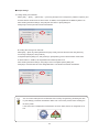
1.Print out [Metallic Color Chart] of Metallic Color System Library from Roland VersaWorks.
① Open [Queue A Properties].
② Click [OK] after selecting [Quality]→([Media Type] & [Mode]).
①
②
2.Select [Media]→[ Print Roland Metallic
Color System Library> Metallic Color Chart].
3.Your confirmation is requested.
Click [OK] to load a file to Roland VersaWorks.
9
4.A job of Metallic Color Chart is loaded to [Queue
A Properties].
Click [RIPping & Printing] in the tool bar after
configuring job settings (Scale, Quality, etc,).
The job is output after ripping.
Each color in the color chart has an
individual name. (ex. RVW-MT-Gold,
RVW-MT-01A)
【 Ex. 】
RVW-MT-Gold
RVW-MT-01A
$'9,&(
There are 3 kinds of color charts in Roland Metallic Color System Library. Use a suitable chart
for your purpose.
◆ Metallic Color Chart
◆ Metallic Color Selector
◆ Metallic Color Chips
Metallic Color Chart
Metallic Color Selector
10
◆ How to create Metallic color data
1.Open "Swatch Libraries" for Metallic Color System Library.
Select [Window] ‒ [Swatch Libraries] ‒ [Roland Metallic Color System Library] from Illustrator [Menu] bar.
①
Small List View
③
②
2.Select a color you like from pre-arranged Metallic Color Chart and apply it (RVW-MT-**) to the fill of
an object.
11
4)Metallic Texture System Library
Roland Metallic Texture System Library is a function to easily print metallic texture patterns like a hair line
or geometoric designs using metallic silver ink. There are 26 kinds of the metallic texture patterns as design
patterns. You can easily express a metallc and texture using this patterns together with CMYK color.
Print the pattern chart of the Metallic Texture System Library in advance and select the metallic texture you
like to use in the chart and then apply it to your garaphic design.
◆ How to output a sample chart
1.Print out [Metallic Color Chart] of Metallic Texture System Library from Roland VersaWorks.
① Open [Queue A Properties].
② Click [OK] after selecting [Quality]→([Media Type] & [Mode]).
②
①
2.Select [Media]→[Print Roland Metallic Texture
System Library > Chart].
3.Your confirmation is requested.
Click [OK] to load a file to Roland VersaWorks.
12
4.A job of Metallic Color Chart is loaded to
[Queue A Properties].
Click [RIPping & Printing] in the tool bar.
The job is output after ripping.
Each color in the color chart has an individual name.
(ex. RTSL-MT-Glitter-050, RTSL-MT-Hologram-010)
【 Ex. 】
RTSL-MT-Glitter-050
RTSL-MT-Hologram-010
13
◆ How to crate Metallic texture data
1.Open "Swatch Libraries" for Roland Metallic Texture System Library.
Select [Window] ‒ [Swatch Libraries] ‒ [Roland Metallic Texture System Library] from Illustrator [Menu] bar.
④ Select "Update" whenever you find the following
①
dialog box.
④
③
Small Thumbnail View
Small List View
②
2.Select a desired color from pre-arranged Metallic Texture Chart as you like and apply it (RTSL-MT-**) to the fill
of an object.
$'9,&(
● When applying Roland Metallic Texture System Library to your design, use the original size
from graphic data creatoin to file output.
● The texture part is displayed with texure and textere name in Illustrator.
14
5) Metallic Silver Gradation
It is possible to create a Metallic Silver Gradation using Metallic color. It can enliven the design of the object
with smooth gradation.
1.Select an object, and then apply the gradation to the fill.
2.Change the color for the gradational object. For example, choose "RVW-MT-15M".
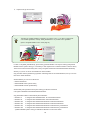
Drag & Drop "RVW-MT-15M" from Roland Metallic Color
System Library to gradient sliders.
(refer to the illustration)
Gradient Slider
3.Change the percentage of color on each
gradient slider. (gradient slider on the left
side >> 30%, gradient slider on the right
side >> 100%)
15
Gradient Slider
4.Adjust the angle and location.
$'9,&(
The effect of metallic gradation is limited in an uniform color. If you like to create multicolor metallic gradation, overlap “RDG_MetallicSilver” on process color's gradation.
(refer to "Original Metallic Color" of the page 8.)
In order to use [RDG_MetallicSilver], [CutContour], [Roland Metallic Color System Library] and [Roland
Metallic Texture System Library], it is necessary to first register them in Adobe Illustrator’s Swatch Library.
There are the above swatch library files in the [C:Program Files\Roland VersaWorks\Swatch\Illustrator]
directory of your PC on which VersaWorks has been installed.
Copy thse files into the [Swatches] (or [Swatch Libraries]) folder of the Adobe Illustrator, and you can use
them in the Adobe Illustrator.
Swatch libraries you can use on BN-20 are
・Roland VersaWorks
・Roland Metallic Color System Library
・Roland Metallic Texture System library
Swatch library file of [Roland Color System Library] on BN-20 is located at
C:\Program Files\Roland VersaWorks\Swatch\Illustrator
Copy destination folders of swatch library file at Illustrator:
・Illustrator 10
C:\Program Files\Adobe\Illustrator 10.0.3\Presets\Swatches
・Illustrator CS
C:\Program Files\Adobe\Illustrator CS\Presets\Swatches
・Illustrator CS2
C:\Program Files\Adobe\Adobe Illustrator CS2\Presets\Swatches
・Illustrator CS3
C:\Program Files\Adobe\Adobe Illustrator CS3\Presets\Swatches
・Illustrator CS4
C:\Program Files\Adobe\Adobe Illustrator CS4\Presets\en_US\Swatches
・Illustrator CS5
C:\Program Files\Adobe\Adobe Illustrator CS5\Presets\en_US\Swatches
**[Roland Metallic System Library] is available for Illustrator CS and new version
16
$'9,&(
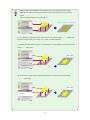
When an object which Metallic Color is applied to laps over the process color's object
(regardless of object's position), the metallic color and the process color are mixed and
printed.
(refer to Original Metallic Color of the page 8)
Mixture of metallic color and yellow color
If you would like to output the process color (Y:100) of the foremost object(“
★ ” : Yellow star)
without being affected by teh metallic color, create your data as bellows:
A) Underlay the same shape of object which [RVW-MT-** 0%] is applied to behind the foremost
object (“
★ ”: Yellow star).
Keep Y 100%
B) Cut out the rear object colored with [RVW-MT-25A] in the form of the foremost object
(“
★ ”: Yellow star).
Keep Y:100%
Same shape of object as the
foremost object
17
$'9,&(
When you create metallic graphic data, it is very useful for you to do it with lalyer funciton
of Adobe Illustrator. For example, let's try to create the graphic data with "Original Metallic
Color" using "Crest of Line".
① Select "Crest" from layer panel.
② Click the option at the upper right of the panel.
③ Select Duplicate 'Crest'.
④ [Crest copy] is created.
②
③
①
④
You can show only the target layer and edit it.
18
2 Printing from Application
Output data from Illustrator to Roland VersaWorks
When printing out the data from Illustrator to Roland VersaWorks, there are two types of data output as
bellow:
1. Output data using a print driver (PS driver)
2. Output data creating an EPS file
There are no differences with regard to print quality, but there are differences on printable area and file size.
The procedures and differences are described below.
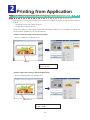
A: How to output data using a Printer Driver (PS Driver)
The size of Artboard is the printable area.
Artboard
Printable area = Artboard
File size - 907 KB
B: How to output data creating an EPS File from Illustrator
The size of Bounding box is the printable area.
Bounding box
Printable area = Bounding box
File size - 76 KB
19
A: Output data Using a Printer Driver (PS Driver)
① Open a file.
② Click [Document Setup] from [File] menu.
Check that the width is 160 mm and the height is 95 mm, and then click [OK].
20
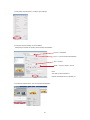
③ Click [Print] on [File] menu to configure print settings.
④ Configure the print settings as shown bellow.
Click [Print] to transfer the printing data to Roland VersaWorks.
Printer = RolandVW
PPD = Default (Roland VersaWorks)
Size = Custom
Width = 160 mm, Height = 95 mm
Note:
The data is just transferred to
Roland VersaWorks and not printed yet.
⑤ The data is loaded into the Job List of Roland VersaWorks.
21
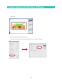
B: Output data Creating an EPS File from Illustrator
① Open the file (file name: XXXX.ai).
② Click [Save As] on [File] menu.
Select the [Illustrator EPS] file format and click [Save As] button.
Click [OK].
22
③ Drag and drop the EPS file into the Job List in Roland VersaWorks to load the file.
$'9,&(
Setting the Margin
When an image data is saved as EPS format in Illustrator, parts of objects such as cut lines may
not be able to be output accurately. In order not to have such a case, configure the margin as
shown bellow.
[A/B Queue Properties] → [File Format] → [EPS Settings]
Enter a margin value of 0.35m and more.
Note : When the image data is scaled (expanded or reduced), the margin of the data is also
expanded or reduced.
NG
Good
23
When Outputting an Image Data with Illustrator 10.0 or later...
Roland VersaWorks features the latest version of the CPSI engine, providing maximum compatibility with
the special effects in Illustrator such as [Transparency] and [Blur].
However, when using complex transparency effects, some special settings may be necessary for proper
printing.
These effects significantly take time for Ripping process, so we recommend that you perform RIP test in order
to check if you can keep enough memory and hard disk space.
Also, when transparency or the following special effects are used, the contour line may be printed instead
of being cut.
[Filter] → [Stylize] → [Drop Shadow]
[Effect] → [Stylize] → [Feather]
[Effect] → [Stylize] → [Drop Shadow]
[Effect] → [Stylize] → [Outer Glow]
[Effect] → [Stylize] → [Inner Glow]
[Effect] → [Rasterize] (only when [Background] is set to [Transparent])
[Object] → [Rasterize] (only when [Background] is set to [Transparent])
[Window] → [Transparency] when [Mode] is set to anything other than [Normal]
[Window] → [Transparency] when [Opacity] is set to anything other than [100%]
[Window] → [Transparency] when [Create a opacity maks] is executed
And also, when the [Background] is set to [Transparent] in the [Document Raster Effects Settings] dialog box,
If you use the following commands from the [Effects] menu, the contour cut line may be printed as well:
[Blur], [Artistic], [Sharpen], [Sketch], [Texture], [Video], [Pixelate], [Brush Strokes], [Stylize], [Distort].
When the contour line is not recognized properly and is printed, change the output settings in Illustrator as
described on the following page. This may correct the problem and the contour cut line may be detected
properly.
When creating artwork:
① Never use the transparency function against the [Fill] or the [Stroke] on an object that contains the contour
cut line.
② Ensure that the [contour line] is on the [very top] layer with all other data underneath it.
$'9,&(
Do not apply the transparency effects to an object when you use spot colors including Metallic
silver. Otherwise, you may have an unexpected output result.
24
● Output Settings
A. Printing directly from Illustrator
Select [File] → [Print] → [Advanced] → [Custom] (Overprint and Transparency Flattener Options) and
uncheck all three check boxes as shown below. In addtion, set the [Raster/Vector Balance] slider to 75.
After checking the above settings, click [OK] and then return to [Print] dialog box.
Click [Print] to send a print file to Roland VersaWorks.
B: Printing after Saving as an EPS File
Select [File]→ [Save As], select [Illustrator EPS] in [Format], enter the file name and click [Save AS].
If a warning is displayed, click [Continue].
In the [EPS Options] dialog box, click [Custom] in [Transparency] and uncheck all three check boxes
as shown below. In addition, set the [Raster/Vector Balance] slider to 75.
After checking the above settings, click [OK] to return to the [EPS Options] dialog box.
Click [OK] to save the EPS file to the designated folder. Load the file into Roland VersaWorks.
$'9,&(
You can confirm if the print and cut data has been correctly recognized by previewing the data
in [Job Settings] of Roland VersaWorks. Make sure to check the preview before sending the
file to the printer.
If the contour line is displayed as a dashed line as shown below, the line is recognized as cut
line.
25
3
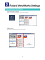
Roland VersaWorks Settings
Basics of Roland VersaWorks
1) Starting Roland VersaWorks
Click an icon to open Roland VersaWorks. The main screen is displayed.
2) Main screen
The main screen is divided into three windows as shown below.
①
③
Main Window
Layout Window
②
Preview Window
26
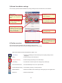
3) Roland VersaWorks settings
You can easily operate Roland VersaWorks by simply clicking the icons and files in the main windows.
Multiple Printer Display
A maximum of four printers
can be connected
Status Display
Indicates a normal connection
between the computer and
printer
Queue A(B) Properties
Configure default settings of
each queue folder
Printer Information
Check the printer information
such as the port number and
the remaining amount of ink
Preferences
Configure settings such as RIP
specification, window display
format, colorimeter, and internet
connection for updates
Job
Data loaded in RIP
Job toolbar
Perform operations such as
the printing and RIPing of
Job List items
4) Toolbar overview
You can perform basic operations using the following toolbar buttons.
The most commonly used buttons are [Job Settings] and [RIPing and Printing].
Note: Data loaded into Roland VersaWorks is called a “Job”
Job Settings
= Open the Job Settings window where layout and quality settings can be
configured
RIPing
= Perform RIPing for the selected job
RIPing and Printing
= Perform RIPing and printing for the selected job
Job Nesting
= Concatenate a number of jobs into a single job (a nested job)
Print Control/Save File
= Save the selected job as a rvw or prt format file
Cancel RIPing& Printing = Cancel RIPing, printing, or other processes
Metafile Deletion
= Delete the metafile for the selected job, restoring the job to its original state
Delete Job
= Delete the selected job
27
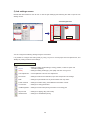
5) Job settings screen
Double-click data loaded into the Job List or click the [Job Settings] after selecting the data to open the Job
Settings screen.
Job Settings Screen
Settings area
Layout area
Job tool buttons
You can configure the following settings using the Job Toolbar.
It is possible to configure the setting easily by using 'Layout' for normal paper sizes and placements, and
'Quality' for printing mode and color settings.
Job Toolbar and Main Functions
Layout
= Settings including media settings, scaling, position, number of copies and
orientation (rotation)
Quality
= Settings including media type, print quality and color management
Color Adjustment = Level adjustment and tone curve adjustment
File Format
= Settings for files such as EPS files, spot color and special color settings
Mark
= Settings for print details such as job information and crop marks
Printer Controls
= Settings for media cutting, feed calibration and heater controls
Cut Controls
= Settings for cutting parameters
Job Management = Settings for action after printing and action for incoming jobs
Clip and Tile
= Settings for clipping, tiling and overlap
Variable Data
= Settings for variable data printing
28
Job Settings and Printing
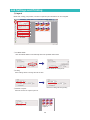
1) Layout
Media size, scaling, print position, number of copies and print orientation can be configured.
①
②
③
④
① Get Media Width
Click 'Get Media Width' to automatically detect the printable media width.
Media width set at the printer.
② Scaling
Enter scaling values to change the size of data.
Enter the scaling values in [Scale]
③ Number of Copies
Enter the number of copies to print out
Number of print
copies: 6
29
④ Print Orientation
Click the icons of orientation to rotate the data by 90 degrees.
2)Quality
Settings for media type, print quality and color management
①
②
③
④
① Media Type and Print Quality
An optimum media profile suited to the media is set by selecting the media types and print quality you need.
Select [Standard] in "Print Quality".
[Draft] is available for CMYK only.
The estimated time for printing is displayed
on each print quality.
30
② Mode
Select mode you like to use.
$'9,&(
There are 3 types of mode - [CMYKMt], [Mt -> CMYK],
[CMYK -> Mt] - on Metallic Silver.
* P7 アドバイス参照
Each print mode is different in the way of printing; therefore, the output result is different even
though you use the same metallic color.
◆ CMYKMt
Print both metallic silver and CMYK color at the same time.
◆ Mt->CMYK
Use the front part and the rear part of a head separetely for
metallic silver ink and CMYK ink
Print CMYK color after metallic silver.
◆ CMYK->Mt
Use the front part and the rear part of a head separetely for
metallic silver ink and CMYK ink
Print metallic silver after CMYK color.
* This mode is available only for SP-CLT
(PET Clear Film, Adhesive).
$'9,&(
When selecting one of 3 types mode (CMYKMt, Mt->CMYK, Metallicsilver), metallic color is
displayed on preview window as gray hatched line.
31
③ Print Direction
Accoring to print quality you select, print direction is automatically selected.
If you select [Standard] in "Print Quality", [Uni-Direction] is automatically selected, If you select [Dradt] in "Print
Quality", [Bi-Direction] is automatically selected.
Uni-Direction :
Print head perform printing during the outbound pass.
Bi-Direction :
The print head perform printing during both the outbound pass
④ Color Settings
and return pass. (Available for CMYK mode printing only)
Select well-suited "Color Settings" for your printing
You can configure the settings of input and output profiles and
matching methods to reproduce the colors of the original data
as precisely as possible in Rland VersaWorks.
Presets are previously optimum configuration of input profiles
and matching methods necessary for color management.
◆ Main Presets ◆
(1) Japan Color:
The standard setting for printed matter produced in most Japanese printing environments.
This preset is suited for color (well known as standard press proofs) in offset printing performed in Japan.
(2) MAX Impact:
This preset is designed for signs and allows for high-intensity output.
For output such as large banners and wall signs, it produces vivid, eye-catching colors and it is possible to
produce deep, well contrasted colors by using input profiles with the broadest color gamuts for both RGB data
and CMYK data.
(3) Sign & Display:
This preset is based on Japan Color and is designed for the signs.
It is able to produce deep colors when printing image data.
Pure colors of CMYK vectors and text are preserved, and it is able to produce primary colors without having the
secondary colors mixed.
(4) MAX Density Japan:
This preset prints image CMYK vectors and text without color conversion. Primary colors are preserved.
$'9,&(
What is Secondary Color?
Even though colors are defined as pure colors such as C100 or Y100 in drawing software like
Illustrator, other color inks are mixed with Cyan or Yellow ink due to matching method in the RIP.
This other colors are called secondary color.
Data = Y100
Output with Secondary Color
32
Preserve Primary Color
3) File Format
Congiure "Spot Color".
Confirm the spot colors you selected
in Metallic Color System Library here,
and then check the box of [Covert Spot
Color].
4) Print
Click [Print] to start printing.
33
Contour Cutting after Lamination
You can remove the printed media and then reload it and perform contour cutting on BN-20.
For instance, perform lamination or other processing after printing, then reload the media and perform contour
cutting.
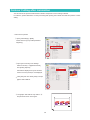
1. Print with crop marks.
① Open [Job Settings]→[Mark].
Check the box of [Crop marks(Print&Cut
Aligment)].
② Open [Cut Controls] in Job Settings.
Select "Print Only" of [Operation Mode]
from [Cutting Options].
Print data is displayed on layout windows.
Coutour cut line (red line) is not displayed.
③ Click [OK] and then select [Print] to output
graphic data to BN-20.
④ The graphic data with the crop makrs(●)
are printed as shown in the figure.
34
2.Remove the media from BN-20.
① Cut off the media from the BN-20.
65mm or more
65mm以上
Leave 65 mm and more of margin from the
edge of the crop marks at the rear side.
60mm or more
65mm以上
3.Reload the media again.
①
1.4mm or more
After lamination, reload the meida again
as follows
① Set the pinch rollers while keeping 1.4mm
and more from the outer line of the crop
marks.
② Set 2 front crop markson the blade
protector.
② Crop mark
③ The alignment of media is no more than 5
degree.
③ Set the media
within 5 degree.
35
Blade protector
4.Perform Contour Cutting.
① Open [Cut Controls] in Job Settings.
② Select "Cut Only" of [Operation Mode] from
[Cutting Options].
The only cut line (red line) is displayed on
layout windows.
③ Click [OK] and then select [Print] to output
cut line data to BN-20.
BN-20 starts contour cutting after detecting
all the crop marks.
$'9,&(
Be sure to perform "Test Cut" before starting contour cutting.
Since the thichness of the media is more thicker due to lamination, you may not be able to cut it
with an original setting of blade force and cut speed.
36
4
BN-20's Utility
How to Open the Utility Window
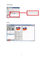
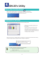
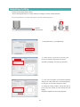
Utility is resident software of BN-20. Click the Utility icon
on the task tray.
You can use it to check "ink levels", "nozzle clogging" and to replace the cutter blades.
In addtion, use this software for any adjustments and maintenance.
Confirmation of Ink levels
Ink and waste fluid levels can be checked in the Ink tab of the Utility window.
A simple bar scale indicates the level of ink in
each cartridge.
* Displayed ink levels are estimates and are
slightly different from the actual ink levels.
* Percentage values also indicate the level of ink
remaining. When the cartridge is removed, [No
Cartridge] message is displayed.
When an ink level is low, a message appears on the Utility icon on the task tray. Check which ink is running
out with the Utility Software and prepare a relevant cartridge for replacement.
The ink in the cartridge is down to 5% full.
Prepare a replacement ink cartridge.
$'9,&(
*A variety of messages are displayed in the Utility window.
Ex. ** Shake the ink cartridge before installing.
Replace the wiper, etc.,
Take necessary action in accordance with the displayed message.
37
Checking Amount of Waste Fluid
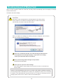
When the waste cartridge is filled with waste fluid, the Utility window automatically opens and displays a message.
Follow the instructions
and replace the waste cartridge.
CAUTION
Remove the waste cartridge after the message appears in the Utility window.
If this procedure is not followed, discharged fluid may overflow from the main
unit and stain your hands or drip and stain the floor.
When you replace the cartridge, the following message is displayed. Take necessary
action in accordancewith the message
Never use a used waste cartridge. The waste fluid may overflow because
the equipment cannot manage it properly. To purchase new cartridge,
contact your authorized dealer or Roland DG.
Never place discharged fluid cartridge near open flame.
These fluids are inflammable.
Never open the cap of the waste cartridge.
If the fluid is spilled or vapor escapes, this may cause a fire risk, or the fumes may
induce nausea.
Dispose of discharged fluid properly and in accordance with Health and Safety regulations.
The discharged fluid is inflammable and contains toxic ingredients. Never burn or incinerate,
or dispose of the discharged fluid with general waste. Do not empty the discharged fluid into a
sewage system, stream or river. There is a risk of environmental impact.
38
Checking Nozzle Condition / Cleaning Method
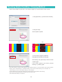
Check nozzle condition of print head. If the nozzle is clogged, you will not be able to print correctly.
① Click [Adjustment] -> [Check Nozzle Condition].
② Click [Test Print].
The test pattern is printed.
OK
NG
Nozzle clogging
Nozzle Deflection
③ If the nozzle is clogged or deflected,
select [Normal Cleaning] and click [Go].
After cleaning, click [Test Print] to check for nozzle
condition again.
If the nozzle condition is not fixed by "Nomal
Cleaning", try cleaning again.
If the nozzle condition is not fixed by "Nomal Cleaning", perform "Medium Cleaning". If the nozzle condition is still not fixed by "Medium
Cleaning", perform "Powerful Cleaning". But "Medium Cleaning" is much more than "Nomal Cleaning" on ink consumption, and
"Powful Cleaning" is much more than "Medium Cleaning" on ink consumption.
If nozzle condition does not improve after several times of Powerful Cleaning, perform [Manual Head Cleaning].
Perform this level of cleaning periodically in accordance with the frequency of use.
(refer to Manual Head Cleaning on the page 45).
39
Bidirectional Adjustment
When printing with four colors, Cyan (C), Magenta (M), Yellow (Y), and Black(K), this machine can perform
"Bidirectional Printing" which means that the head prints when moving in out and home directions. The
bidirectional pri nting is much faster, but subtle misalignment occurs during the outbound and return passes
which reduces image quality.If the bidirectional adjustment is inaccurate, the print quality appears grainy as
shown on the photograph below, results in blurred image. The operation to correct these misalignments is
called "Bidirectional Adjustment" As this misalignment differs depending on head height and media thickness, it
is necessary to perform adjustments for each kindof media.
Bidirectional Adjustment <NG>
Bidirectional Adjustment <OK>
① Click [Adjustment] -> [Bidirectional adjustment].
② Click [Test Print].
The test pattern is printed.
Read the on-screen instructions and then enter
a value in the [New Value] box. (▲mark is the
present value)
③ Read the on-screen instructions and then enter
a value in the [New Value] box and Click [Apply].
(The value in [Present Value] changes to the
entered value.)
40
Feed Calibration
Media feeding distance slightly changes depending on the media thickness. If this feeding distance changes
greatly, the bandings appear in the printing and in extreme cases result in white gaps.
Feed calibration is a function to correct errors in the media feeding amount caused by differences in media
thickness.
Media feeding correction can improve printing quality by correcting the dot landing location.
① Click [Adjustment] -> [Calibrate Sheet Feeding
Amount].
② Click [Test Print].
The test pattern is printed.
Read the on-screen instructions and then enter
a value in the [New Value] box. (▲mark is the
present value)
③ Read the on-screen instructions and then enter
a value in the [New Value] box and Click [Apply].
(The value in [Present Value] changes to the
entered value.)
41
Adjusting Cutting
Perform the test cutting before cutting.
Use the following dimension as a rough estimate for setting the amount of blade extension.
Amount of blade extension = Thickness of the material + Thickness of the backing paper / 2
0.1mm
Material
Backing paper
Min. 0 mm
Max. 2.5mm
① Click [Adjustment] -> [Cut Adjustment].
② Check values in [Current Cut Force], [Cut
Current Cut Speed], and [Current Cut Times].
After that Click [Apply]. Test cutting is performed
③ If the circle and square can be peeled separately
and there is a faint blade mark on the backing paper,
it is OK (you do not need to change the value).
To change the cutting condition, change the value in
[Cut Force], [Cut Speed], and [Cut Times] and click
[Apply].
Repeat the adjustment until correctly adjusted.
42
Adjusting Printing & Cutting
Depending on the media thickness, sometimes printing and cutting positions are very slightly
out of alignment. It is recommended to set correction values to suit the media.
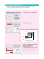
① Click [Adjustment] -> [Print_Cut Adjustment].
② Click [Print and Cut Pattern].
The test pattern is printed.
Feed
Print position
+
Cut position
0.2mm
-
Scan
0.3mm
+
-
③ Follow the on-screen instructions and enter the
values for [New Value for Scanning]
and [New Value for Feeding].
Ex. Enter the values for "New Value for Scanning :
- 0.3mm" "New Value for Feeding" : 0.2mm" here.
Click [Print_Cut Adjustment] again to confirm
aligment. Repeat it until correclty adjusted.
43
Crop Cut Adjustment
Depending on the material of the media, the positioning of printing and cutting may be misaligned even
when you're using crop marks. Make corrections for misaligned printing and cutting for the media you're using.
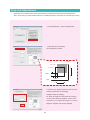
① Click [Adjustment] -> [CropCut Adjustment].
② Click [Print and Cut Pattern].
The test pattern is printed.
Feed
Print position
+
Cut position
0.2mm
-
Scan
0.3mm
+
-
③ Follow the on-screen instructions and enter the
values for [New Value for Scanning]
and [New Value for Feeding].
Ex. Enter the values for "New Value for Scanning :
- 0.3mm" "New Value for Feeding" : 0.2mm" here.
Click [Print_Cut Adjustment] again to confirm
aligment. Repeat it until correclty adjusted.
44
5
User Maintenance
Manual Cleaning
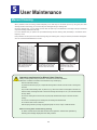
When problems such as missing nozzles frequently occur and they are not fixed up even by using the print head
cleaning function of the Utility, you can clean the print head again using a cleaning stick.
Using the cleaning stick, you can directly remove dust, dirt and lump of ink attached on the edge of the print head that
may cause missing nozzles and ink drop.
It is more effective that you perform the print-head cleaning with the cleaning stick periodically in accordance to the
frequency of use.
If the problems do not improve even after cleaning using the cleaning stick, it may be that the print head is damaged or
worn out. Contact Roland DG Service Center.
Nozzle clogging
Dust and dirt stick to the
print head and prevent
normal firing of ink.
Ink spots
Ink gathers around dirt and
grime near the print head
and ink drops are formed.
Dragged dirt
Dragging occurs when dirt
around the print head
comes into contact with
media.
Important requirements for Manual Head Cleaning
Always carefully follow the procedures in accordance with the instructions.
Otherwise a sudden movement of the machine may cause injury.
Remove media before cleaning.
To prevent the head from drying out, complete the cleaning within 30 minutes. After 30 minutes a warning alarm
will sound.
Only use the included cleaning sticks. Any other tool, e.g. cotton bud or similar is not designed for this task and
will become fluffy and damage the head. Please order cleaning sticks directly from us or your authorized Roland
DG Corp. dealer.
Do not use a cleaning stick more than once; the print quality will deteriorate. Dispose of the stick after each
cleaning.
Do not soak a used cleaning stick in cleaning fluid; the cleaning fluid will deteriorate.
Do not rub the nozzle surface of the head.
Clean the sponge section by stroking very lightly and gently. Do not rub, scrape, or flatten the section.
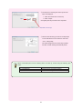
When a warning alarm sounds during cleaning
An alarm sounds 30 minutes after the start of the operation. Perform the operation by
following the message displayed in the Utility window.
45
① Click [Adjustment] ->[Manual Head Cleaning].
② Manual Cleaning procedures are displayed.
Wait for the head to stop moving, and then remove
the maintemance cover.
Click [Next].
③ Manual Head Cleaning procedures are displayed.
1.Move the carriage to the extreme left.
2.Soak the cleaning stick in cleaing liquid.
3.Clean the metal frame of the head side.
Click [Next] after all procedures are completed.
Metal frame of head
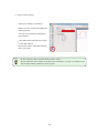
Cleaning stick
Cleaning liquid
Clean the heads using stick and liquid
46
④ Procedures for cleaning the head cups and the
wiper are displayed.
1. Clean the metal frame of head cap.
2. Clean a wiper.
Wiper
Click [Next] after all procedures are completed.
Metal frame of head cups
⑤ Manual Head Cleaning procedures are displayed.
Fix the maintenance cover and then close front
cover. Click [finish].
The head caridge returns to head cap's position
and then normal cleaning automatically starts.
$'9,&(
When consumable parts such as cleaning sticks are used up, reorder using the following item
codes.
Item Code
Name
KIT.CLEANING(SL)
Cleaning Kit (for UV/solvent printers)
SET.CLEANER STICK TX712A 10PCS Contains 10 cleaning sticks
47
6
Ink and Media
ECO-SOL MAX INK Usage Conditions
1) When using the printer
Do not place the printer in any place where it will be subjected to direct sunlight or high temperature. If the
printer is heated by direct sunlight, the nature of the ink can change, which may have adverse effects on the
head and other components.
If the printer is placed in a cold environment, low temperatures may cause the ink to freeze which may cause
damage to the head.
● Operation environment --> Temperature 20-32ºC, Humidity 35-80% (no condensation)I
● Ink usage environment --> Temperature 15-35ºC, Humidity 35-80% (no condensation)I
2) Ink storage
ECO-SOL MAX INK should be stored under the following storage conditions, and ink cartridges should be kept
out of direct sunlight. In addition, ink cartridges should be shaken before use.
● Ink storage conditions ⇒ Temperature 5-40ºC, Humidity 20-80% (no condensation)
Media
1) Roland DG Media
Roland DG brand media developed specially for use with ECO-SOL MAX INK, it can not only be used for ICCbased color profiles critical to color management, but also make high quality printing possible using waterbased ink by conducting various print controls including variable dot control matched to media characteristics
by the Roland DG RIP software VersaWorks.
It is recommended that customers who require accurate color reproduction and high-quality images use Roland
DG media.
2) Non-Roland DG Media
ECO-SOL MAX INK can print on so-called commercial non-coated media.]
Output quality varies depending on the media used.When using a non-Roland DG media for the first time, it is
recommended that you perform a print test and use the media once its compatibility with ECO-SOL MAX INK
has been confirmed.
48
ECO-SOL MAX INK and Media
ECO-SOL MAX INK is not an organic solvent and is environmentally friendly. However, as with other solvent inks,
it has the following characteristics, particularly with regard to vinyl media,
When using a non-Roland DG media for the first time, it is recommended that you perform a print test and use the
media once its compatibility with ECO-SOL MAX INK has been confirmed.
ECO-SOL MAX INK Characteristics (Vinyl Media)
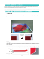
1) Shrinkage
The solvent component of ECO-SOL MAX INK and the printer heater cause shrinkage mainly at the printed
portions of vinyl media.
Contraction following cutting of the printed surface
48 hours later
0.5mm
Contraction
2) Warping
When cutting the sheet along the printed surface or performing standard cutting, the cross section may warp as
shown in the figure.
Contraction of the media can cause the glued surface to rise and dry, weakening bond strength. If printing is
carried out under these circumstances, the printed surface may not adhere with sufficient strength.
Backing
Glue
Release paper
49
Measures Against Warping and Shrinkage
Handling media as described below can reduce warping and contraction.
① Print with a margin (add a non-printed area).
② When it is absolutely necessary to cut the sheet along the printed surface, cut the sheet directly
before printing.
③ Areas without a margin warp upwards after printing.It is recommended that roll printing is performed where
possible.
Considerations when printing and cutting
It is advised that cutting is performed with a margin when printing and cutting.When the design necessitates
that cutting is performed along the printed surface, postponing the removal of waste until printing is finished can
reduce warping.
Margin present
No margin
Waste removed
Waste not removed
48 hours later
48 hours later
50
51
Copyright © 2011 Roland DG Corporation
● Unauthorized reproduction of this guidebook is prohibited without legal permission.
● Windows is a trademark or registered trademark of Microsoft Corporation in the United States and other countries.
● Macintosh and Mac OS are trademarks or registered trademarks of Apple Computer, Inc. in the United States and other countries.
● Adobe, Adobe Illustrator, Adobe Photoshop, PostScript, PostScript 3 and the PostScript logo are trademarks or registered
trademarks of Adobe Systems Incorporation in United States and other countries.
● All other company names and product names are trademarks or registered trademarks of their respective holder.
Published 2011/11/8
Ver.1.00