1
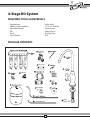
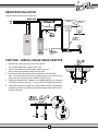
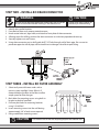
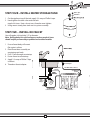
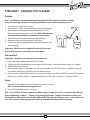
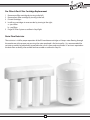
REVERSE OSMOSIS
WATER FILTRATION SYSTEM
MODEL EWR 4075
INSTRUCTION MANUAL
Excalibur Water Systems
142 Commerce Park Drive, Unit M & N
Barrie, Ontario L4N 8W8 CANADA
www.excaliburwater.com
2013.05.7446
4-Stage RO System
REQUIRED TOOLS & MATERIALS
•
•
•
•
•
•
Tape Measure
Phillips Head Screwdriver
Adjustable Wrench
File
Pencil
Pan or Bucket
•
•
•
•
•
•
Utility Knife
1/8” & 1/2” Drill Bits
Center Punch
Safety Glasses
Masking Tape
Drill
PACKAGE CONTENTS
Sediment
Cartridge
Carbon
Cartridge
Reverse Osmosis
Membrane
Carbon
Cartridge
Angle Valve
Adapter
S
C
RO
C
Teflon® Tape
Tank Valve
W Drain Fitting
U 6’ of 1/4” White Tube
1
V Faucet
Adapter
PLAN FOR INSTALLATION
Prior to installation, we recommend you read the entire manual. This will not only familiarize you with the
system, but it will help you determine the best location for installation whether under a sink or in a remote
location. Helpful diagrams follow.
PREPARE SITE FOR INSTALLATION
1 Prior to starting, close the cold water shut-off valve.
2 Temporarily place tank and filter assembly into cabinet to ensure adequate space and proper positioning.
3 Remove tank and filter from cabinet and set aside.
INSTALLATION OVERVIEW
There are eight easy steps to installing your RO unit. They are as follows:
Step 1 - Install Angle Valve Adapter
Step 2 - Install RO Drain Connector
Step 3 - Install RO Filter Assembly
Step 4 - Install Water Storage Tank
Step 5 - Install Tank Valve
Step 6 - Install RO Faucet
Step 7 - Connect Tubing
Step 8 - Install RO System and Drain in Remote Location
Step 9 - Sanitize, Pressure Test, Purge System
NOTE: You must check and comply with all local plumbing codes.
STANDARD INSTALLATION
1/4” White Tube
to Drain
1/4” White Tube
to Reverse Osmosis
Carbon
Cartridge
Reverse Osmosis
Membrane
Carbon
Cartridge
Angle
Valve
Adapter
Sediment
Cartridge
Tank Valve
S
C
RO
C
Restrictor
2
REMOTE INSTALLATION
(requires nearby water source and drain)
3/8” White Tube
to Faucet
3/8” White Tube
to Tank
1/4” White
Tube to
Drain Point
2”
Minimum
STEP ONE – INSTALL ANGLE VALVE ADAPTER
1 Identify the cold water line in the sink cabinet.
Turn off the cold water supply to the sink.
2 Turn on the kitchen faucet to release pressure and
allow water to completely drain from the line.
3 Disconnect the cold water line from the lower shut off valve.
Note: You may need to shorten the supply line pipe using a hacksaw or
pipe cutter to accommodate the Adapter if pipe is rigid.
4 Holding the Angle Valve Adapter in an upright position (see diagram
in Package Contents on page 1), screw onto the threaded shut off valve.
5 Screw the cold water supply line to the male threads of the Adapter
using the nut that was previously connecting the cold water line to
the shut off valve.
3
Angle
Valve
Adapter
STEP TWO – INSTALL RO DRAIN CONNECTOR
! WARNING
!
Be sure that all electrical appliances and outlets are turned off
at the circuit breaker before working in the cabinet area.
1
2
3
4
5
6
CAUTION
Please wear safety glasses to
protect eyes when drilling.
Identify drain outlet location.
From back of foam seal, remove protective cover.
Knock center hole out, align holes, and attach to front plate of drain connector.
Allowing room for drilling, position the drain connector on sink drain pipe above drain trap.
Securely tighten nuts and screws.
Using drain connector port as drill guide, drill 7/32” hole through wall of drain pipe. Be sure not to
penetrate opposite side of pipe, and be careful not to damage side of drain port fitting.
Angle
Valve
Adapter
STEP THREE – INSTALL RO FILTER ASSEMBLY
1 Select easily accessible area under sink to
mount system manifold. Note: Allow 4-6”
clearance below the filter to the floor to allow
ample space for filter changes.
2 Mark holes for mounting screws using built-in
bracket on back of manifold.
3 Drill two pilot holes for mounting brackets
using 1/8” drill bit.*
4 Insert mounting screws into the wall leaving
approximately 3/8” of each screw exposed.
5 Hang manifold on mounting screws.
*
!
CAUTION
Use caution not to drill into anything beyond the cabinet wall.
4
STEP FOUR – INSTALL WATER STORAGE TANK
H Teflon® Tape
Tank Valve
1 On the nipple on top of the tank, apply 2-3 wraps of Teflon® tape.
2 Hand-tighten the tank valve onto the tank
nipple 3-4 times. Note: do not cross thread or over-tighten.
3 Using mount stand, place tank next to system assembly.
STEP FIVE – INSTALL RO FAUCET
You will need a sink top hole 1/2” in diameter.
Note: Drilling holes into solid surfaces or surfaces made of stone
should only be performed by a qualified and certified installer.
1 Ensure faucet body will mount
flat against surface.
2 Place faucet base assembly on
countertop and mark.
3 Drill ½” hole through countertop.
4 Fasten faucet to countertop.
5 Apply 2-3 wraps of Teflon® Tape
to faucet.
6 Thread on faucet adaptor.
Faucet Adapter
3/8” White Tube to Faucet
1/4” White Tube
to Drain
1/4” White Tube
to Reverse Osmosis
5
Carbon
Cartridge
Reverse Osmosis
Membrane
Carbon
Cartridge
Angle
Valve
Adapter
Sediment
Cartridge
3/8” White Tube
to Tank
S
C
RO
C
Restrictor
STEP SIX – CONNECT TUBING
Install tubing for water supply line from
angle valve adapter to manifold inlet.
Note: Do not bend or crimp tubing during this step.
1 With utility knife, cut the 1/4" white tubing squarely
to desired length.
2 With water, wet one end of tubing and push into
the angle valve adapter approximately 5/8” until it stops.
3 Wet other end of tubing and push into the manifold
“INLET” approximately 5/8” until it stops.
Note: It is not necessary to remove tubing for routine maintenance and filter exchanges,
however, it may easily be disconnected if necessary. To disconnect, turn off water supply to
system and press in white collar around fitting while pulling tubing out with other hand.
Install tubing for water supply line from manifold outlet to faucet.
1 Identify length of 3/8”white tubing necessary to
connect to manifold outlet labeled “FAUCET” to
faucet adapter.
2 Cut tubing squarely with utility knife. Do not
discard remaining tubing.
3 With water, wet one end of tubing and push into
manifold outlet labeled “FAUCET” approximately
5/8” until it stops.
4 With water, wet other end of tubing, push into faucet adapter
approximately 5/8” until it stops.
Connect tubing from manifold to tank.
1 Use remaining white tubing set aside earlier and identify length
needed to connect tank outlet labeled “TANK” on manifold to tank.
2 Cut white tubing square with a utility knife.
3 Insert tubing into port of tank valve (previously connected to tank)
and tighten tank valve nut.
4 Insert other end of white tubing into outlet of manifold labeled
“TANK” approximately 5/8” until it stops.
Note: For servicing, tubing lengths should allow for
removal of assembly from mount screws.
6
STEP SIX – CONNECT TUBING (Continued)
Drain fitting to Restrictor.
1 Locate membrane drain port on lower membrane side.
2 By pushing down on the white collar while pulling
plug with other hand, remove black plug from
membrane filter drain port.
3 Identify length necessary to connect to drain port.
4 With utility knife, cut the 1/4" white tubing squarely to
desired length.
5 Insert restrictor into end of white tubing.
6 Insert white tubing into fitting on bottom of membrane filter approximately 5/8” until it stops.
7 Gently tug on white tubing to ensure it is firmly seated in fitting.
1/4” White Tube
to Drain
Carbon
Cartridge
Reverse Osmosis
Membrane
Carbon
Cartridge
Angle
Valve
Adapter
Sediment
Cartridge
Tank Valve
S
C
RO
C
1/4” White Tube
to Reverse Osmosis
Restrictor
Connect flow restrictor to drain adapter connection.
1 Attach 1/4" tubing to collet quick connect on flow restrictor.
2 Cut enough 1/4” white tubing to route in as straight as possible without any twists, kinks,
loops or valleys.
3 Cut end of 1/4” white tubing with utility knife to desired length.
4 Insert 1/4” white tubing to drain connection approximately 5/8" until it stops.
5 Gently tug on white tubing to ensure it is firmly seated in fitting.
7
NOTE: THIS STEP FOR REMOTE LOCATIONS ONLY
STEP SEVEN – INSTALL RO SYSTEM & DRAIN
1 Determine if tubing is long enough to reach drain. If yes, insert restrictor in end of tubing and insert this
end into drain port on membrane. If no, replace with tubing of adequate length and insert restrictor into
end of tubing. Insert this end of tubing into drain port on membrane.
2 Cut enough 1/4” white tubing to drain port.
3/8”
3/8”
Restrictor
1/4” White
Tube to
Drain Point
2”
Minimum
8
STEP EIGHT – SANITIZE, TEST & PURGE
Sanitize
Note: Sanitization is recommended immediately after RO Filter System installation and any
inner-part servicing. The person sanitizing should have clean hands during this process.
1 Shut off water supply to RO system.
2 Open faucet. If tank is not empty, allow to drain until empty.
3 With included eyedropper and household bleach (5.25%),
disconnect white tubing from tank valve. Note: Bleach needs
to be handled according to manufacturer’s instructions.
4 Add 3ml bleach into open end of tank white tubing.
5 Reconnect tank and white tubing to tank valve.
6 Sanitization will be completed during the following pressure
test and purge.
Important: Bleach must be completely removed from system
before drinking water. See Purge instructions below.
Pressure Test
Important: Complete sanitization prior to pressure test.
1
2
3
4
Open cold water supply valve to RO Filter System.
To purge air from the plumbing system, open kitchen faucet. Close faucet when water runs smooth.
Confirm RO faucet is closed.
Within approximately 2 hours, pressure will start to build in the RO Filter System. Carefully inspect all
connections and fittings while this pressure buildup occurs.
5 Check for leaks. If leaks are found, fix by ensuring all tubing is cut squarely and fully inserted. Also confirm
there are no scratches, dents or notches at tubing end. If there are, squarely cut 1” off and re-insert.
Purge
1 Open RO faucet and let water flow through system for 24 hours.
Note: Flow rate will be slow during this time.
2 Close RO faucet after purge is complete.
Note: Your RO Filter System is ready for use when purge is complete, however, you will not have filtered
water immediately. It takes 1 – 3 hours to completely fill the tank. The flow rate will be less than your
kitchen faucet. Water will run to the drain while the RO Filter System is filtering water – even when not in
use. This is normal. Water going to drain will stop automatically when tank is at capacity.
9
Filter Replacement
1 Close angle valve located on cold water supply hose to shut off water
supply to the RO Filter System.
2 Turn cartridge from right to left until unit releases. Gently pull down to
remove from head. Discard used cartridge.
Note: Place a bucket or pan under system to catch any water drips.
3 Hold new cartridge with label slightly facing left. The two nozzles on top
of cartridge should be toward the back of the Filter System, and the two
extended flanges should be out to each side.
Note: Part No. SMFPP2005TL should be in stage 1, Part No. SMF CBC2005TL
should be in stages 2 and 4, and Part No. ROTWRM75 should be in stage 3.
4 Lift cartridge straight up into the manifold until the two nozzles seat into
the manifold ports, and the two extended flanges are flush with the
manifold.
5 Turn cartridge from left to right until it stops.
6 Turn on cold water shut-off valve and RO faucet. Check for leaks.
7 Pressure test and Purge per Step Eight.
10
4-STAGE RO SYSTEM – MODEL EWR 4075
U.S.
Metric
Membrane Production1
75 ± 7 gpd
(283 ± 26 lpd)
Membrane TDS Reduction1
96.6% minimum
96.6% minimum
System Production2
45 gpd
170 lpd
TDS Reduction2
97.5%+ typical
97.5%+ typical
Maximum TDS
1000 ppm
1000 ppm
Maximum water hardness @ 6.9pH
10 gpg
2.64 gpL
Maximum Chlorine in water
3.0 ppm
3.0 ppm
Supply water pH limits
4-10
4-10
Drain (reject water) Flow
3-5 x product flow
3-5 x product flow
Empty Storage Tank Precharge
5-7 psi air
35-48 kPa air
Storage Tank Capacity2
4.0 gallons
15 liters
Supply water pressure limits
40-100 psi
280-689 kPa
Supply water temperature limit
40-100⁰ F
5-40⁰ C
Efficiency3
19%
19%
Recovery 4
30.6%
30.6%
Specifications – Qualified System Performance
Because the performance of a Reverse Osmosis Membrane is highly dependent upon pressure,
temperature and TDS, the following should be used for comparison purposes only.
1. Industry standards measure RO Membranes performance with no back pressure on the product water,
at 60 psig (414kPa) and 77°F (25°C). Further conditions on the above are 250 ppm TDS and a 30.6%
recovery rate. Production rate and TDS reduction figures are for a new Membrane that has been rinsed
for 24 hours. The production rate of a new Membrane can decrease by 10% per year or more,
depending upon the scaling and fouling tendencies of the Feed Water.
2. Measured at 50 psi, 77°±2°F, and 717 mg/l TDS per NSF/ANSI Standard 58.
3. Efficiency rating means the percentage of the influent water to the system that is available to the user
as reverse osmosis treated water. Under operating conditions that approximate typical daily usage.
4. Recovery rating means the percentage of the influent water to the membrane portion of the system
that is available to the user as reverse osmosis treated water when the system is operated without a
storage tank or when the storage tank is bypassed.
11
Non-potable Water Sources:
Do not attempt to use this product to make safe drinking water from non-potable water sources. Do not use
the system on microbiologically unsafe water, or water of unknown quality without adequate disinfection
before or after the system. This system is certified for cyst reduction and may be used on disinfected water
that may contain filterable cysts.
Arsenic Reduction:
This system shall only be used for arsenic reduction on chlorinated water supplies containing detectable
residual free chlorine at the system inlet. Water systems using an inline chlorinator should provide a one
minute chlorine contact time before the reverse osmosis system.
Installations in The Commonwealth of Massachusetts:
The Commonwealth of Massachusetts requires installation be performed by a licensed plumber and do not
permit the use of saddle valves. Plumbing code 248--CMR of the Commonwealth of Massachusetts must be
followed in these cases.
The product water shall be tested periodically to verify the system is performing satisfactorily.
Product Water Testing:
The Reverse Osmosis System contains a replaceable membrane cartridge critical for the effective reduction
of total dissolved solids (TDS).
Replacement of the reverse osmosis membrane cartridge:
The reverse osmosis system contains a replaceable membrane cartridge critical to the efficiency of the
system. This membrane should be replaced every 18 months, or more often based on your local water. Only
replace the reverse osmosis membrane with a part approved for use in your Reverse Osmosis system.
12
SYSTEM MAINTENANCE
Prefilter/Postfilter
The pre-filters (sediment- stage 1 and carbon - stage 2) and post-filter (carbon - stage 4) are replaceable
cartridges, and it is recommended replacing these every 6 months. You may need to replace more often
with high water usage or high sediment level. Replacing these cartridges timely will protect the RO
membrane from high levels of chlorine and/or sediment. As these filters build up with sediment, you may
notice slower water output.
RO Membrane Cartridge
The RO membrane is located in stage 3. This membrane is a tightly wound membrane which reduces the
dissolved solids and organic matter. Cartridge life depends on pH and supply water hardness. Higher pH
shortens membrane life by causing pin-hole leaks. When output water quality and production rate
decrease, it is time to replace the membrane cartridge, typically after 24 months.
Flow rate and output are determined by 3 factors:
1 Incoming water temperature
2 Total dissolved solids (TDS) present in supply water
3 Incoming water pressure
Lower temperatures are directly proportional to slower flow rate. All membranes are tested at 77°F.
Incoming water temperature should not exceed 100°F. The RO Filter System should also not be installed in a
location susceptible to freezing.
The more TDS in the supply water, greater filter time is required. Incoming TDS should not exceed 1000 ppm.
Higher water pressure enables a higher flow rate. Pressure must be above 40 psi for proper system
operation. You may consider installing a permeate pump or booster pump if your pressure is below 40 psi.
RO Cartridge Replacement
1
2
3
4
5
Remove the pre-filter cartridges first to relieve pressure on the RO filter.
Turn RO filter to left and remove.
Remove post-filter cartridge.
Discard cartridges.
Install new cartridges in reverse order turning to the right to secure:
a – Post-filter (stage 4)
b – RO membrane (stage 3)
c – Pre-filter (stage 2)
d – Pre-filter (stage 1)
6 Purge RO Filter System as outlined in Step Eight.
13
Pre-Filter & Post-Filter Cartridge Replacement
1
2
3
4
Remove pre-filter cartridge by turning to the left.
Remove post-filter cartridge by turning to the left.
Discard cartridges.
Install new cartridges in reverse order by turning to the right:
a – post-filter
b – pre-filters
5 Purge RO Filter System as outline in Step Eight.
Drain Flow Restrictor
The restrictor is vital for proper operation of the RO membrane cartridge as it keeps water flowing through
the membrane at the proper rate ensuring the water produced is the best quality. It is recommended the
restrictor assembly be periodically inspected to be sure it is clean and unrestricted. If service is required on
the drain flow assembly, disassemble and reassemble as outlined in Step Six.
14
Excalibur Water Systems
142 Commerce Park Drive, Unit M & N
Barrie, Ontario L4N 8W8 CANADA
www.excaliburwater.com