1
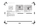
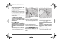
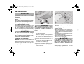
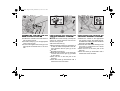
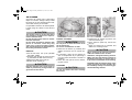
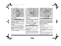
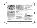
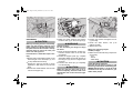
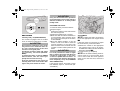
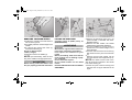
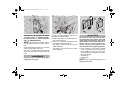
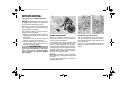
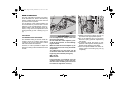
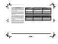
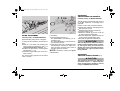
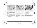
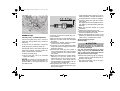
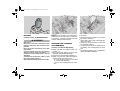
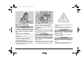
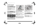
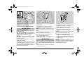
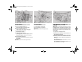
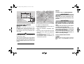
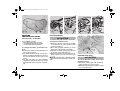
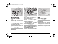
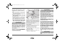
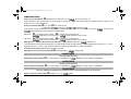
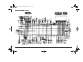
Ing-02.fm Page 52 Friday, December 17, 1999 11:16 AM
2%'5,!2 3%26)#% ).4%26!,3 #(!24
OPERATIONS TO BE CARRIED OUT BY THE APRILIA Official Dealer (WHICH CAN BE CARRIED OUT EVEN BY THE USER)
Component
After running-in
[1000 km (625 mi)]
Spark plugs
Air filter
Engine oil filter
S
Engine oil filter (on oil tank)
P
Every 7500 km
(4687 mi) or 8 months
Every 15000 km
(9375 mi) or 16 months
C (*)
S (*)
C
S
S (*)
P
Light operation/direction
C
Fork
C
Light system
C
C
Safety switches
C
C
Clutch fluid
C
Brake fluid
C
Coolant
C
Engine oil
S
Tyres
C
Tyre pressure
R
Engine idling rpm
R
S (*)
every 1000 km (625 mi): C
every month: R
R
Engine oil pressure warning light LED
at every start: C
Drive chain tension and lubrication
Brake pad wear
every 1000 km (625 mi): C
before every trip and every 7500 km (4687 mi): C
C = check and clean, adjust, lubricate or change, if necessary; P = clean; S = change; R = adjust.
Carry out the maintenance operations more frequently if you use the vehicle in rainy and dusty areas, on uneven ground or
on racetracks.
(*) = In case of use on racetracks, change every 3750 km (2343 mi).
52
use and maintenance SL mille
Ing-02.fm Page 53 Friday, December 17, 1999 11:16 AM
OPERATIONS TO BE CARRIED OUT BY THE APRILIA Official Dealer
Component
After running-in
[1000 km (625 mi)]
Every 7500 km
(4687 mi) or 8 months
Rear suspension linkage bearings
Steering bearings and steering
Every 15000 km
(9375 mi) or 16 months
C
C
Wheel bearings
C
C
Tappet clearance
R
Braking systems
C
Cooling system
R
C
C
Clutch fluid
every 2 years: S
Brake fluid
every 2 years: S
Coolant
every 2 years: S
Fork oil
After the frist 7500 km (4687 mi): S / every 22500 km (14000 mi): S
Brake pads
if worn: S
Nut, bolt, screw tightening
C
Suspensions and attitude
C
Fuel pipes
C
C
C
every 4 years: S
C = check and clean, adjust, lubricate or change, if necessary; P = clean; S = change; R = adjust.
Carry out the maintenance operations more frequently if you use the vehicle in rainy and dusty areas, on uneven ground or
on racetracks.
use and maintenance SL mille
53
Ing-02.fm Page 54 Friday, December 17, 1999 11:16 AM
)$%.4)&)#!4)/. $!4!
It is a good rule to write down the frame
and engine numbers in the space provided
in this manual.
The frame number can be used for the purchase of spare parts.
NOTE Do not alter the identification
numbers if you do not want to incur severe
penal and administrative sanctions. In particular, the alteration of the frame number
results in the immediate invalidity of the
guarantee.
54
use and maintenance SL mille
FRAME NUMBER
The frame number is stamped on the right
side of the steering column.
ENGINE NUMBER
The engine number is stamped on the rear
part of the engine, near the pinion.
Frame no.
Engine no.
Ing-02.fm Page 55 Friday, December 17, 1999 11:16 AM
#(%#+).' 4(% %.').% /), ,%6
%, !.$ 4/00).' 50
Carefully read p. 39 (ENGINE OIL) and
p. 51 (MAINTENANCE).
Periodically check the engine oil level,
change the oil after the first 1000 km (625
mi) and successively every 7500 km (4687
mi), see p. 56 (CHANGING THE ENGINE
OIL AND THE OIL FILTER).
In case of use on racetracks, change every
3750 km (2343 mi).
TO CARRY OUT THE CHECKING:
a CAUTION
The engine oil level must be checked
with warm engine.
If the check is carried out with cold engine, the oil level may temporarily lower
below the “MIN” mark.
This is not a problem, provided that the
engine oil pressure warning light LED
“j” does not come on, see p. 16 (INSTRUMENTS AND INDICATORS TABLE).
◆
◆
Start the engine, see p. 43 (STARTING).
Allow the engine to idle for about 15-20
minutes, or ride the vehicle on a country
road for approximately 15 km (9.5 mi).
◆
◆
Stop the engine.
Keep the vehicle in vertical position, with
the two wheels resting on the ground.
◆ Check the oil level in the transparent
pipe (1) through the appropriate slot provided on the left fairing.
MAX = maximum level
MIN = minimum level.
The difference between “MAX” and “MIN”
amounts to approximately 460 cm#.
◆ The level is correct when the oil almost
reaches the “MAX” mark.
a CAUTION
Never exceed the “MAX” mark, nor
leave the oil below the “MIN” mark, in
order to avoid serious damage to the
engine.
If necessary, top up the engine oil by proceeding as follows:
◆ Position the vehicle on the side stand on
firm and level ground.
◆ Unscrew and remove the filling cap (2).
a CAUTION
Do not put additives or other substances into the oil.
If you use a funnel or other similar
items, make sure that they are perfectly
clean.
NOTE Use high-quality 15W-50 oil, see
p. 90 (LUBRICANT CHART).
◆
Top up the tank and restore the correct
level, see p. 90 (LUBRICANT CHART).
use and maintenance SL mille
55
Ing-02.fm Page 56 Friday, December 17, 1999 11:16 AM
#(!.').' 4(% %.').% /),
!.$ 4(% /), &),4%2
a CAUTION
The engine oil and the oil filter change
operations may be difficult for unskilled
operators.
If necessary, contact an APRILIA Official
Dealer.
If you want to carry them out personally, follow the instructions given below.
Carefully read p. 39 (ENGINE OIL) and
p. 51 (MAINTENANCE) carefully.
Periodically check the engine oil level, see
p. 55 (CHECKING THE ENGINE OIL LEVEL AND TOPPING UP) change the oil after
the first 1000 km (625 mi) and successively
every 7500 km (4687 mi).
a CAUTION
In case of use on racetracks, change
every 3750 km (2343 mi).
a CAUTION
When warmed up, the engine contains
hot oil; therefore, while carrying out the
operations described here below be
particularly careful, in order to avoid
burns.
◆
◆
If the vehicle is used in dusty areas,
change the oil more frequently.
CHANGING THE ENGINE OIL:
NOTE The oil flows out completely and
without problems when it is warm and
therefore more fluid: to achieve this condition, the engine should run for approximately twenty minutes.
56
use and maintenance SL mille
◆
◆
◆
◆
Position the vehicle on the side stand on
firm and level ground.
Position a container (1) with more than
4000 cm# capacity in correspondence
with the drain plug (2) positioned on the
tank.
Unscrew and remove the drain plug (2)
positioned on the tank.
Unscrew and remove the filling cap (3).
Drain the oil and let it drop for a few minutes inside the container (1).
Check and if necessary replace the sealing washer of the drain plug (2) positioned on the tank.
◆
Screw and tighten the drain plug (2) on
the tank.
Drain plug (2) driving torque:
15 Nm (1.5 kgm).
◆ Move the container (1) and position it under the engine base, in correspondence
with the drain plug positioned on the engine (4).
◆ Unscrew and remove the drain plug positioned on the engine (4).
◆ Drain the oil and let it drip inside the container (1) for a few minutes.
a CAUTION
Do not dispose of the oil in the environment. Put it in a sealed container and
take it to the filling station where you
usually buy it or to an oil salvage center.
◆
Remove the metal residues from the
drain plug (4) magnet.
Ing-02.fm Page 57 Friday, December 17, 1999 11:16 AM
◆
Screw and tighten the drain plug (4).
Driving torque of the drain plug (4) positioned on the engine: 12 Nm (1,2 kgm).
CHANGING THE ENGINE OIL FILTER
Change the engine oil filter after the
first 1000 km (625 mi) and successively
every 7500 km (4687 mi) (or every time
you change the oil).
◆
◆
Unscrew the two screws (5) and remove
the cover (6).
Remove the engine oil filter (7).
a CAUTION
Do not use filters that have already
been used.
◆
◆
Spread an oil film on the sealing ring (8)
of the new engine oil filter.
Fit the new engine oil filter.
◆
Put back the cover (6), screw and tighten
the two screws (5).
CLEANING THE ENGINE OIL FILTER
ON THE TANK
◆
Connect the pipe (12) and tighten the
new clamp (10).
a CAUTION
Clean the engine oil filter (9) on the tank
after the first 1000 km (625 mi) and successively every 15000 km (9375 mi) (or
every two engine oil changes).
Do not put additives or other substances into the oil.
If you use a funnel or other similar
items, make sure that they are perfectly
clean.
NOTE Prepare a pipe clamp (10) to re-
NOTE Use high-quality 15W-50 oil, see
place the original one (special type).
◆
Loosen the clamp (11) and disconnect
the pipe (12).
◆ Unscrew and remove the engine oil filter
(9) positioned on the tank and clean it
with a jet of compressed air.
◆ Check the seal of the engine oil filter (9)
positioned on the tank; screw and tighten
it.
Engine oil filter (9) driving torque:
30 Nm (3.0 kgm).
p. 90 (LUBRICANT CHART).
◆
◆
◆
◆
Pour about 3500 cm# of engine oil
through the filling opening (13), see p. 90
(LUBRICANT CHART).
Tighten the filling cap (3).
Start the engine, see p. 43 (STARTING)
and let it idle for about one minute, in order to ensure the filling up of the engine
oil circuit.
Check the oil level and top up if necessary, see p. 55 (CHECKING THE ENGINE OIL LEVEL AND TOPPING UP).
use and maintenance SL mille
57
Ing-02.fm Page 58 Friday, December 17, 1999 11:16 AM
!33%-",).' 4(% 0).3 &/2 4(%
2%!2 3500/24 34!.$ &
0/3)4)/.).' 4(% 6%()#,% /.
4(% 2%!2 3500/24 34!.$ &
0/3)4)/.).' 4(% 6%()#,% /.
4(% &2/.4 3500/24 34!.$ &
◆
NOTE Have someone help you keep the
◆
◆
◆
Position the vehicle on the side stand on
firm and level ground.
★ Position the pin (1) on the appropriate
seat on the rear fork.
★ Screw and tighten the screw (2) in the
appropriate threaded hole in the rear
fork.
vehicle in vertical position with the two
wheels on the ground.
◆
◆
◆
◆
◆
◆
58
use and maintenance SL mille
★Loosen the knob (3).
★Move the fork support (4), positioning it
so that the width corresponds to the distance between the two pins (1) on the
rear fork.
★Tighten the knob (3).
Make the two housings on the stand (4)
coincide with the two pins (1) provided
on the vehicle.
Rest one foot on the rear part of the
stand (5).
Push the stand (5) downwards until it
reaches the end of its stroke.
◆
◆
◆
Position the vehicle on the appropriate
rear support stand, see beside (POSITIONING THE VEHICLE ON THE REAR
SUPPORT STAND &).
Insert the two ends of the stand (6) in the
two holes (7) positioned on the lower
ends of the front fork.
Rest one foot on the front part of the
stand (6).
Push the stand (6) downwards until it
reaches the end of its stroke.
Ing-02.fm Page 59 Friday, December 17, 1999 11:16 AM
!)2 #,%!.%2
Check the air cleaner every 7500 (4687
mi)km or 8 months, change it every 15000
km (9375 mi) or more frequently if the vehicle is used on dusty or wet roads.
It is possible to clean the air cleaner partially after using the vehicle on this kind of
roads.
a CAUTION
The partial cleaning of the filter does
not exclude or postpone the replacement of the filter itself.
Do not start the engine if the air cleaner
has been removed.
Do not clean the filtering element with
petrol or solvents, since they may
cause a fire in the fuel supply system,
with serious danger for the persons in
the vicinity and for the vehicle.
REMOVAL
◆ Lift the fuel tank, see p. 66 (LIFTING
THE FUEL TANK).
◆ Unscrew and remove the seven screws
(1) that fasten the filter case cover (2).
◆ Remove the filter case cover (2).
◆ Extract the air cleaner (3).
a CAUTION
Plug the opening with a clean cloth, in
order to prevent any foreign matter to
get ito the suction ducts.
PARTIAL CLEANING
a CAUTION
Do not press or strike the metal net of
the air cleaner (3).
Do not use screwdrivers or alike.
◆
◆
◆
Seize the air cleaner (3) vertically and
strike it more than once on a clean surface.
If necessary, clean the air cleaner (3)
with a compressed air jet (directing it
from the inside towards the outside of
the filter).
Clean the outer part of the air cleaner,
(3) with a cloth.
CHANGING
a CAUTION
◆
◆
◆
Replace the air cleaner (3) with a new
one of the same type.
Every 7500 km (4687 mi), remove the
plug (4).
Empty its content into a container and
deliver it to a salvage centre.
a CAUTION
When cleaning the filtering element,
make sure that there are no tears.
Otherwise, change the filtering element.
Make sure that the filtering element is
positioned correctly, in such a way as
to prevent non-filtered air from entering.
Remember that the untimely wear of the
piston segments and the cylinder may
be caused by a faulty or uncorrectly positioned filtering element.
Do not use filters that have already
been used.
use and maintenance SL mille
59
Ing-02.fm Page 60 Friday, December 17, 1999 11:16 AM
&2/.4 7(%%,
a CAUTION
The disassembly and reassembly of the
front wheel may be difficult for unskilled
operators. If necessary, contact an
APRILIA Official Dealer.
If you want to perform these operations
personally, keep to the following instructions.
Carefully read p. 51 (MAINTENANCE).
While disassembling and reassembling
the wheel, be careful not to damage the
brake pipes, the discs and the pads.
NOTE
To remove the front wheel it is
necessary to use the appropriate front and
rear support stands &.
60
use and maintenance SL mille
DISASSEMBLY
◆ Position the vehicle on the appropriate
rear support stand, see p. 58 (POSITIONING THE VEHICLE ON THE REAR
SUPPORT STAND &).
◆ Position the vehicle on the appropriate
front support stand, see p. 58 (POSIT I O N I N G T H E V EH I C L E O N T H E
FRONT SUPPORT STAND &).
a CAUTION
Make sure that the vehicle is stable.
◆
Have someone keep the handlebar
steady in running position, so that the
steering is locked.
Brake caliper screw (1) driving torque:
50 Nm (5 kgm).
◆ ★ Unscrew and remove the two screws
(1) that fasten the front brake caliper (2).
◆ ★ Withdraw the brake caliper (2) from
the disc, leaving it attached to the pipe
(3).
a CAUTION
Never pull the front brake lever after removing the calipers, otherwise the pistons may go out of their seats, thus
causing the outflow of the brake fluid. In
this case consult your APRILIA Official
Dealer, who will carry out the proper
maintenance operation.
Wheel nut (4) driving torque:
80 Nm (8 kgm).
◆
Loosen and remove the nut (4), taking
the washer.
◆ ★ Partially unscrew the two screws (5)
from the wheel pin clamp.
◆ Put a support (6) under the tyre, in such
a way as to keep the wheel in its position
after loosening it.
◆ Withdraw the wheel pin (7) from the left
side.
◆ Remove the wheel withdrawing it from
the front and take the left spacer ring (8)
if it has come out of its seat.
Ing-02.fm Page 61 Friday, December 17, 1999 11:16 AM
aWARNING
Upon reassembly of the brake caliper,
replace the caliper fastening screws (1)
with two new screws of the same type.
◆
REASSEMBLY
Carefully read p. 51 (MAINTENANCE).
a CAUTION
While reassembling the wheel, be careful not to damage the brake pipes, discs
and pads.
The arrow on the wheel side indicates
the rotation direction. Upon reassembly, make sure that the wheel is positioned correctly: the arrow must be visible on the left side of the vehicle.
◆
◆
◆
Spread a film of lubricating grease on the
whole length of the wheel pin (7), see
p. 90 (LUBRICANT CHART).
If the left spacer ring (8) has come out of
its seat on the wheel during disassembly,
correctly position it there.
Position the wheel between the fork rods
on the support (6).
aWARNING
Danger of injury.
Do not introduce your fingers to align
the holes.
◆
◆
◆
◆
◆
Move the wheel until its central hole and
the holes on the fork are aligned.
Introduce the wheel pin (7) completely.
Position the washer and tighten the nut
(4) manually.
Lock the rotation of the wheel pin (7).
Tighten the nut (4) completely.
Wheel nut (4) driving torque:
80 Nm (8 kgm).
a CAUTION
Proceed with care, in order not to damage the brake pads.
◆
★ Insert the brake caliper (2) on the disc
and position it so that its fastening holes
and the holes on the support are aligned.
★ Screw and tighten the two screws (1)
that fasten the brake caliper.
Brake caliper screw (1) driving torque:
50 Nm (5 kgm).
◆ With pulled front brake lever, press the
handlebar repeatedly, thrusting the fork
downwards. In this way the fork rods will
settle properly.
◆ ★ Tighten the two screws (5) of the
wheel pin clamp.
Wheel pin clamp screw (5) driving
torque: 22 Nm (2,2 kgm).
◆
Make sure that the following components
are not dirty:
– tyre;
– wheel;
– brake discs.
aWARNING
After reassembly, pull the front brake lever repeatedly and check the correct
functioning of the braking system.
Check the wheel centering.
Have the driving torques, centering and
balancing of the wheel checked by your
APRILIA Official Dealer, in order to avoid
accidents that may be harmful for you
and/or other people.
use and maintenance SL mille
61
Ing-02.fm Page 62 Friday, December 17, 1999 11:16 AM
2%!2 7(%%,
a CAUTION
The disassembly and reassembly of the
rear wheel may be difficult for unskilled
operators. If necessary, contact an
APRILIA Official Dealer.
If you want to perform these operations
personally, keep to the following instructions.
Carefully read p. 51 (MAINTENANCE).
Before carrying out the following operations, let the engine and the silencer
cool down until they reach room temperature, in order to avoid burns.
While disassembling and reassembling
the wheel, be careful not to damage the
brake pipe, the disc and the pads.
62
use and maintenance SL mille
NOTE
To remove the rear wheel it is
necessary to use the appropriate rear support stand &.
DISASSEMBLY
◆ Position the vehicle on the appropriate
rear support stand, see p. 58 (POSITIONING THE VEHICLE ON THE REAR
SUPPORT STAND &).
Wheel nut (1) driving torque:
120 Nm (12 kgm).
◆ Loosen and remove the nut (1), taking
the washer.
◆ Put a support (2) under the tyre, in such
a way as to keep the wheel in its position
after loosening it.
◆ Withdraw the wheel pin (3) from the left
side.
◆
Make the wheel advance and release the
drive chain (4) from the crown gear (5).
a CAUTION
Check the position of the chain tighteners (6-7), in order to be able to reassemble them correctly.
◆
◆
Remove the right (6) and left (7) chain
tighteners.
Remove the entire wheel withdrawing it
from behind.
a CAUTION
Do not operate the rear brake lever after
removing the wheel, since the pins may
go out of their seats and cause brake
fluid leakages.
In this case consult your APRILIA Official
Dealer, who will carry out the proper
maintenance operation.
Ing-02.fm Page 63 Friday, December 17, 1999 11:16 AM
REASSEMBLY
◆
a CAUTION
Before proceeding with the reassembly,
make sure that support plate (8) of the
brake caliper (9) is positioned correctly;
the plate slot must be inserted in the appropriate stop pin (10) in the inner part
of the rear fork right rod.
Insert the disc in the brake caliper carefully.
◆
◆
◆
Spread a film of lubricating grease on the
whole length of the wheel pin (3), see
p. 90 (LUBRICANT CHART).
Position the right (6) and left (7) chain
tighteners in their seats on the rear fork
arms.
Position the wheel between the rear fork
rods on the support (2).
Make the wheel advance and position
the drive chain (4) on the crown gear (5).
◆
aWARNING
◆
Danger of injury.
Do not introduce your fingers to align
the holes.
◆
◆
◆
◆
Move the wheel backwards, until its central hole and the holes on the rear fork
are aligned.
Rotate the support plate (8), complete
with brake caliper (9) and with fulcrum on
the stop pin (10), until it is aligned with
the holes.
Introduce the wheel pin (3) completely
from the left side.
a CAUTION
Make sure that the wheel pin (3) is inserted completely, with the head in the
appropriate seat on the left chain tightener (7).
Position the washer and tighten the nut
(1) manually.
Check the chain tension, see p. 64
(DRIVE CHAIN).
Tighten the nut (1).
Wheel nut (1) driving torque:
120 Nm (12 kgm).
◆
Make sure that the following components
are not dirty:
– tyre;
– wheel;
– brake discs.
a CAUTION
Check the wheel centering.
Have the driving torques, centering and
balancing of the wheel checked by your
APRILIA Official Dealer, in order to avoid
accidents that may be harmful for you
and/or other people.
use and maintenance SL mille
63
Ing-02.fm Page 64 Friday, December 17, 1999 11:16 AM
a CAUTION
Carry out the maintenance operations
more frequently if you use the vehicle in
difficult conditions or on dusty and/or
muddy roads.
$2)6% #(!).
Carefully read p. 51 (MAINTENANCE).
The vehicle is equipped with an endless
chain, in which a ring link joint is not used.
a CAUTION
An excessive slackening of the chain
may cause noise or make the chain rattle, with consequent wear of the shoe
and of the chain guide plate.
Periodically check the slack and adjust
it if necessary, see beside (ADJUSTMENT).
To change the chain, contact an APRILIA
Official Dealer, who will ensure you
prompt and accurate servicing.
Incorrect maintenance may cause the
untimely wear of the chain and/or damages to the pinion and/or the crown.
64
use and maintenance SL mille
CHECKING THE SLACK
To check the slack, proceed as follows:
◆ Stop the engine.
◆ Position the vehicle on the side stand on
firm and level ground.
◆ Position the shifting lever in neutral.
◆ Make sure that the vertical oscillation, in
an intermediate point between pinion
and crown in the lower part of the chain,
is about 25 mm.
◆ Move the vehicle forwards, or turn the
wheel, in order to be able to check the
vertical oscillation of the chain even
when the wheel turns; the slack must be
constant in all the rotation phases of the
wheel.
a CAUTION
If in some positions the slack is higher
than in others, this means that there are
crushed or seized links; in this case,
contact an APRILIA Official Dealer. To
prevent the risk of seizures, lubricate the
chain frequently, see p. 65 (CLEANING
AND LUBRICATION).
If the slack is uniform, but higher or lower
than 25 mm, adjust it, see beside (ADJUSTMENT).
ADJUSTMENT
NOTE To adjust the chain it is necessary
to use the appropriate rear support stand
&.
If after the check it is necessary to adjust
the chain tension, proceed as follows:
◆ Position the vehicle on the appropriate
rear support stand, see p. 58 (POSITIONING THE VEHICLE ON THE REAR
SUPPORT STAND &).
◆ Loosen the nut (1) completely.
NOTE For the wheel centering fixed reference marks (2-3) are provided, which
can be seen inside the chain tightener
seats on the rear fork arms, before the
wheel pin.
Ing-02.fm Page 65 Friday, December 17, 1999 11:16 AM
CHECKING THE WEAR OF CHAIN,
PINION AND CROWN
Further, check the chain and sprockets
and make sure that they do not present:
– damaged rollers;
– loose pins;
– dry, rusty, crushed or seized links;
– excessive wear;
– lacking O rings;
– sprocket or teeth excessively worn or
damaged.
a CAUTION
◆
◆
Loosen the two lock nuts (4).
Act on the adjusters (5) and adjust the
chain slack, making sure that the reference marks (2-3) are correctly positioned
on both sides of the vehicle.
◆ Tighten the two lock nuts (4).
◆ Tighten the nut (1).
Wheel nut driving torque (1):
120 Nm (12 kgm).
◆
Check the chain slack, see p. 64
(CHECKING THE SLACK).
If the chain rollers are damaged, the
pins are loose and/or the O rings are
damaged or lacking, it is necessary to
change the whole chain unit (both
sprockets and chain).
Lubricate the chain frequently, especially if there are dry or rusty parts.
The crushed or seized links must be lubricated and made work again.
If this is not possible, contact an APRILIA
Official Dealer, who will provide for
changing the chain.
◆
Finally, check the wear of the rear fork
protection shoe.
CLEANING AND LUBRICATION
a CAUTION
The drive chain is provided with O rings
among the links, in order to keep the
grease inside them.
Carry out the adjustment, lubrication,
cleaning and change of the chain with
great care.
Never wash the chain with water jets,
steam jets, high-pressure water jets and
highly inflammable solvents.
◆ Wash the chain with naphtha or kerosene. If it tends to rust quickly, intensify
the maintenance intervals.
Lubricate the chain every 1000 km (625
mi) or whenever necessary.
◆ After washing the chain and letting it dry,
lubricate it with spray grease for chains
provided with sealing rings, see p. 90
(LUBRICANT CHART).
a CAUTION
The lubricants for chains available on
the market can contain substances that
are dangerous for the rubber sealing
rings of the chain.
NOTE Do not use the vehicle soon after
lubricating the chain, since due to the centrifugal force the lubricant would be
sprayed outwards and dirty the surrounding areas.
use and maintenance SL mille
65
Ing-02.fm Page 66 Friday, December 17, 1999 11:16 AM
2%-/6).' 4(% 2)$%2 3!$$,%
,)&4).' 4(% &5%, 4!.+
◆
Carefully read p. 30 (FUEL) and p. 51
(MAINTENANCE).
Position the vehicle on the side stand on
firm and level ground.
◆ ★ Partially raise the rear side edge of the
saddle.
◆ ★ Unscrew and remove the screw (1)
and take the bushing (2).
Screw (1) driving torque:
12 Nm (1.2 kgm).
◆ Raise and remove the saddle (3).
NOTE Upon reassembly, insert the front
tang of the saddle in the appropriate seat.
a CAUTION
Before leaving, make sure that the saddle (3) is properly positioned and locked.
66
use and maintenance SL mille
a WARNING
Risk of fire.
Wait until the engine and the exhaust silencer have completely cooled down.
Fuel vapours are noxious for your
health.
Before proceeding, make sure that the
room in which you are working is properly ventilated.
Do not inhale fuel vapours.
Do not smoke and do not use naked
flames.
DO NOT DISPOSE OF FUEL IN THE ENVIRONMENT.
◆
◆
◆
◆
◆
Remove the passenger seat, see p. 27
(UNLOCKING / LOCKING THE PASSENGER SEAT).
Remove the rider saddle, see beside
(REMOVING THE RIDER SADDLE).
Turn the handlebar in such a way as to
position the front wheel straight, in the
travel direction.
Unscrew and remove the two screws (4)
that fasten the front part of the fuel tank
(5).
Remove the fuel tank support rod (8)
from the relevant anchorage seats (6-7).
NOTE The rubber-covered end of the
stick (8) must be introduced in the central
hole of the steering pin.
◆
Lift the front part of the fuel tank (5) and
introduce the rod (8) as indicated in the
figure.
Ing-02.fm Page 67 Friday, December 17, 1999 11:16 AM
#(%#+).' 4(% "2!+% 0!$ 7%!2
Carefully read p. 31 (BRAKE FLUID recommendations), (DISC BRAKES)
and p. 51 (MAINTENANCE).
NOTE The following information refer to
a single braking system, but are valid for
both.
Check the brake pad wear every 7500 km
(4687 mi) and before every trip.
The wear of the disc brake pads depends
on the use, on the kind of drive and on the
road.
a WARNING
Check the wear of the brake pads, especially before every trip.
.
To carry out a rapid checking of the wear of
the pads, proceed as follows:
◆ Position the vehicle on the side stand on
firm and level ground.
◆ Carry out a visual check between the
disc and the pads, proceeding:
– from below, on the front part, for the front
brake calipers (1);
– from below, on the rear part, for the rear
brake caliper (2).
a CAUTION
The excessive wear of the friction material would cause the contact of the pad
metal support with the disc, with consequent metallic noise and production of
sparks from the caliper; braking efficiency, safety and soundness of the
disc would thus be negatively affected.
◆
If the thickness of the friction material
(even of one pad only) has reduced to
about 1 mm (or if even only one of the
wear indicators is not visible any longer),
change both pads.
– Front pad (3).
– Rear pad (4).
NOTE Have the pads changed by your
aprilia Official Dealer.
use and maintenance SL mille
67
Ing-02.fm Page 68 Friday, December 17, 1999 11:16 AM
).30%#4).' 4(% &2/.4
!.$ 2%!2 3530%.3)/.3
Carefully read p. 51 (MAINTENANCE).
NOTE Have the front fork oil changed by
an aprilia Official Dealer, who will ensure
you prompt and accurate servicing.
Have the front fork oil changed after the
first 7500 km (4687 mi) and successively
every 22500 km (14000 mi).
Every 7500 km (4687 mi), carry out the following checking operations:
◆ With pulled front brake lever, press the
handlebar repeatedly, thrusting the fork
downwards.
The stroke must be gentle and there
must be no trace of oil on the rods.
◆ Check the fastening of all the components and the functionality of the front
and rear suspension joints.
a CAUTION
If you notice irregularities in the operation or if the help of a qualified technician is necessary, contact your APRILIA
Official Dealer.
&2/.4 3530%.3)/.
The front suspension consists of an hydraulic fork connected to the steering column by means of two plates.
For the setting of the vehicle attitude, each
rod of the fork is provided with an upper
screw (1) for the adjustment of the hydraulic braking with extended shock absorber,
a lower screw (2) for the adjustment of the
hydraulic braking with compressed shock
absorber and an upper nut (3) for the adjustment of the spring preload.
NOTE It is possible to adjust the attitude
of the vehicle, by changing the height of its
front part.
For this type of adjustment, contact an
aprilia Official Dealer.
68
use and maintenance SL mille
ADJUSTING THE FRONT FORK
The standard setting of the front fork is
such as to satisfy most driving conditions
at low and high speed, either with reduced
load and full load.
However, it is also possible to adjust the
setting according to the intended use of the
vehicle.
Ing-02.fm Page 69 Friday, December 17, 1999 11:16 AM
a CAUTION
For the adjustment, always start from
the most rigid setting (adjuster completely rotated clockwise).
Do not force the rotation of the adjusters (1-2) beyond the end of stroke in
both directions, in order to avoid any
damage.
Use the notches (1-2) provided on the
adjusters as reference marks for the adjustment of the hydraulic braking with
compressed and extended shock absorber.
Give the adjusters (1-2) 1/8 turn at a time
and turn the adjusting nut (3) one notch
at a time. Test the vehicle repeatedly on
the road, until obtaining the optimal adjustment.
Set the same spring preload and hydraulic braking for both rods: a different setting of the rods decreases the stability of
the vehicle while riding.
When the spring preload is increased, it
is necessary to increase also the hydraulic braking, in order to avoid sudden
jerks while riding.
Upper screw adjusters
(1) (2.25 turns in total)
Function
Recommended kind
of road
Notes
Standard adjustment
By rotating them
clockwise (H)
Increase of the hydraulic
braking with extended shock
absorber
Smooth or normal roads
By rotating them
anticlockwise (S)
Decrease of the hydraulic
braking with extended shock
absorber
Roads with uneven surface
Rider and passenger
Solo rider
From end of stroke (completely closed), give 1.5
anticlockwise turns (opening).
Lower screw adjusters By rotating them clockwise By rotating them
(2) (2 turns in total)
(H)
anticlockwise (S)
Function
Increase of the hydraulic
Decrease of the hydraulic
braking with compressed
braking with compressed
shock absorber
shock absorber
Recommended kind
Smooth or normal roads
Roads with uneven surface
of road
Notes
Rider and passenger
Solo rider
Standard adjustment
From end of stroke (completely closed), give 1.5
anticlockwise turns (opening).
Upper adjusting
nuts (3)
(8 notches in total)
Function
Attitude
Recommended kind
of road
Notes
Standard adjustment
By rotating them clockwise
(screwing)
Spring preload increase
The vehicle is more rigid
Smooth or normal roads
By rotating them
anticlockwise
(unscrewing)
Spring preload decrease
The vehicle is less rigid
Roads with uneven surface
Rider and passenger
Solo rider
From end of stroke (completely closed), turn the adjusting
nut 5 notches anticlockwise (opening).
use and maintenance SL mille
69
Ing-02.fm Page 70 Friday, December 17, 1999 11:16 AM
2%!2 3530%.3)/.
The rear suspension consists of a springshock absorber unit, fixed to the frame by
means of silent-blocks and to the rear fork
by means of lever systems.
For the setting of the vehicle attitude, the
shock absorber is provided with a screw
adjuster (1) for the adjustment of the hydraulic braking with extended shock absorber, a ring nut for the adjustment of the
spring preload (2) and a locking ring nut
(3).
ADJUSTING
THE REAR SHOCK ABSORBER
The standard setting of the rear shock absorber is such as to satisfy most driving
conditions at low and high speed, either
with reduced load and full load.
However, it is also possible to adjust the
setting according to the intended use of the
vehicle.
a CAUTION
For the adjustment, always start from
the most rigid setting.
Do not rotate the screw adjuster (1) beyond its limit position, to avoid damaging the thread.
Make sure that the screw adjuster (1) always snaps and is not in any intermediate position.
The adjusting ring nut must not be
screwed for more than 44 mm from the
beginning of the thread (see figure).
MIN = 38 mm
MAX = 44 mm
If this measure is exceeded, even the
slightest unevenness on the road surface will cause sudden jerks and it will
be useless to adjust the screw (1).
70
use and maintenance SL mille
◆
◆
◆
◆
Slightly unscrew the locking ring nut (3)
by means of the appropriate spanner.
Act on the adjusting ring nut (2) (shock
absorber spring preload adjustment)
(see figure).
If necessary, adjust the screw (1) (adjustment of the hydraulic braking with extended shock absorber) (see table).
Once the optimal attitude has been obtained, tighten the locking ring nut (3)
completely.
Ing-02.fm Page 71 Friday, December 17, 1999 11:16 AM
a CAUTION
Adjust the spring preload and the hydraulic braking with extended shock absorber according to the conditions of
use of the vehicle.
When the spring preload is increased, it
is necessary to increase also the hydraulic braking with extended shock absorber, in order to avoid sudden jerks
while riding.
If the vehicle attitude is set for full-load
riding, it is advisable not to rotate the
screw (1) leftwards (anticlockwise), in
order to avoid sudden jerks while riding. If necessary, contact an APRILIA Official Dealer.
Gradually turn the screw (1) adjuster
giving 2-3 clicks per time, and the adjusting ring (2) giving one turn per time.
Screw adjuster (1)
(27 clicks)
Function
Recommended kind
of road
Notes
Standard adjustment
Adjusting ring nut (2)
Function
Attitude
Recommended kind of
road
Notes
By rotating it clockwise (H) By rotating it
anticlockwise (S)
Increase of the hydraulic
Decrease of the hydraulic
braking with extended shock braking with extended shock
absorber
absorber
Smooth or normal roads
Roads with uneven surface
Rider and passenger
Solo rider
From end of stroke (completely closed), turn the screw
adjuster 15 clicks anticlockwise (opening).
By screwing it
Spring preload increase
The vehicle is more rigid
Smooth or normal roads
By unscrewing it
Spring preload decrease
The vehicle is less rigid
Roads with uneven surface
Rider and passenger
Solo rider
Test the vehicle repeatedly on the road,
until obtaining the optimal adjustment.
use and maintenance SL mille
71
Ing-02.fm Page 72 Friday, December 17, 1999 11:16 AM
!$*534).'
4(% !##%,%2!4/2 #/.42/,
Carefully read p. 51 (MAINTENANCE).
)$,).' !$*534-%.4
Carefully read p. 51 (MAINTENANCE).
Adjust the idling every time it is irregular.
To carry out this operation, proceed as follows:
◆ Ride for a few miles until reaching the
normal running temperature, see p. 17
(Coolant temperature indicator “h”).
◆ Position the gear lever in neutral (green
warning light “ q ” on).
◆ Check the engine idling rpm on the revolution counter.
The engine idling speed must be about
1250 ± 100 rpm.
If necessary:
Turn the adjusting knob (1).
BY SCREWING IT (clockwise), you increase the rpm.
BY UNSCREWING IT (anticlockwise),
you decrease the rpm.
◆ Twist the throttle grip, accelerating and
decelerating a few times to make sure
that it functions correctly and to check if
the idling speed is constant.
◆
NOTE If necessary, contact your aprilia
Official Dealer.
The idle stroke of the throttle grip must be
2 – 3 mm, measured on the edge of the
grip itself.
If this is not the case, proceed as follows:
◆ Position the vehicle on the side stand on
firm and level ground.
◆ Withdraw the protection element (2).
◆ Loosen the lock nut (3).
◆ Rotate the adjuster (4) in such a way as
to restore the prescribed value.
◆ After the adjustment, tighten the lock nut
(3) and check the idle stroke again.
◆ Put back the protection element (2).
a CAUTION
After the adjustment, make sure that the
rotation of the handlebar does not modify the engine idling rpm and that the
throttle grip returns smoothly and automatically to its original position after
being released.
!$*534).'
4(% #/,$ 34!24 #/.42/, e
a CAUTION
The operations necessary to adjust the
cold start control “e” require specific
skills and therefore should be carried
out by an APRILIA Official Dealer.
72
use and maintenance SL mille
Ing-02.fm Page 73 Friday, December 17, 1999 11:16 AM
#(%#+).' 4(% 3)$% 34!.$
!.$ 4(% 3!&%49 37)4#(
Carefully read p. 51 (MAINTENANCE)
and p. 78 (CHECKING THE SWITCHES).
The side stand (1) must rotate without hindrances.
Carry out the following checks:
◆ The springs (2) must not be damaged,
worn, rusty or weakened.
◆ The side stand must rotate freely, if necessary grease the joint, see p. 90 (LUBRICANT CHART).
The side stand (1) is provided with a safety
switch (3) that has the function to prevent
or interrupt the operation of the engine with
the gears on and the side stand (1) down.
To check the proper functioning of the
safety switch (3), proceed as follows:
◆ Seat on the vehicle in driving position.
◆ Fold the side stand (1).
◆ Start the engine, see p. 43 (STARTING).
◆ With released throttle grip (4) (Pos. A)
and engine idling, pull the clutch lever (5)
completely.
◆
◆
Engage the first gear, pushing the shifting lever (6) downwards.
Lower the side stand (1), thus operating
the safety switch (3).
At this point:
– the engine must stop;
– the “side stand down” warning light “\”
must come on.
a CAUTION
If the engine does not stop, contact an
APRILIA Official Dealer.
use and maintenance SL mille
73
Ing-02.fm Page 74 Friday, December 17, 1999 11:16 AM
30!2+ 0,5'3
Carefully read p. 51 (MAINTENANCE).
Check the spark plugs every 7500 km
(4687 mi), change them every 15000 km
(9375 mi).
In case of use on racetracks, change the
spark plugs every 3750 km (2343 mi).
Periodically remove the spark plugs and
clean them carefully, removing carbon deposits; change them if necessary.
To reach the spark plugs:
◆ Lift the fuel tank, see p. 66 (LIFTING
THE FUEL TANK).
NOTE The vehicle is equipped with two
spark plugs per cylinder. The following operations refer to one spark plug only, but
are valid for both.
74
use and maintenance SL mille
To remove and clean the spark plug, proceed as follows:
◆ Remove the cap (1) of the spark plug (2).
◆ Remove any trace of dirt from the spark
plug base.
◆ Introduce the special spanner provided
in the tool kit on the spark plug.
◆ Insert the 13 mm fork spanner provided
in the tool kit in the hexagonal seat of the
spark plug spanner.
◆ Unscrew the spark plug and extract it
from its seat, taking care to prevent dust
or other substances from getting inside
the cylinder.
◆ Make sure that there are neither carbon
deposits, nor corrosion marks on the
electrode and on the central porcelain
part; if necessary, clean them with the
special cleaners for spark plugs, with an
iron wire and/or a metal brush.
◆ Energetically blow some air, in order to
prevent the removed residues from getting into the engine.
If the spark plug has crackings on the insulating material, corroded electrodes or
excessive deposits, it must be changed.
◆ Check the spark plug gap with a thickness gauge.
The gap must be 0.6 – 0.7 mm; if necessary adjust it, carefully bending the earth
electrode.
◆ Make sure that the washer is in good
conditions.
◆ Position the spark plug in its seat.
◆ Screw the spark plug manually, using the
spanner provided in the tool kit.
◆ Tighten the spark plug by means of the
spanner you will find in the tool kit, giving
it half a turn to compress the washer.
Spark plug driving torque:
20 Nm (2 kgm).
a CAUTION
The spark plug must be well tightened,
otherwise the engine may overheat and
be seriously damaged.
Use the recommended type of spark
plugs only, see p. 87 (TECHNICAL DATA), in order not to compromise the life
and performance of the engine.
◆
◆
Position the spark plug cap (1) properly,
so that it does not come off due to the vibrations of the engine.
Put back the fuel tank, see p. 66 (LIFTING THE FUEL TANK).
Ing-02.fm Page 75 Friday, December 17, 1999 11:16 AM
NOTE
"!44%29
Carefully read p. 51 (MAINTENANCE).
a WARNING
Risk of fire.
Keep fuel and other flammable substances away from the electrical components.
Never invert the connection of the battery cables.
Connect and disconnect the battery
with the ignition switch in position “m”,
otherwise some components may be
damaged.
Connect first the positive cable (+) and
then the negative cable (–).
Disconnect following the reverse order.
This vehicle is provided with a
maintenance-free battery and no operation
is necessary, excepting occasional checks
and the recharge when required.
#(%#+).' !.$ #,%!.).'
4(% 4%2-).!,3
Carefully read beside (BATTERY).
◆
◆
◆
◆
Make sure that the ignition switch is in
position “m”.
Remove the rider saddle, see p. 66 (REMOVING THE RIDER SADDLE).
Remove the red protection element (1).
Make sure that the cable terminals (2)
and the battery terminals (3) are:
– in good conditions (and not corroded
or covered with deposits);
– covered with neutral grease or Vaseline.
If necessary:
◆ Disconnect first the negative (–) and then
the positive cable (+).
◆ Brush with a wire brush to eliminate any
sign of corrosion.
◆ Reconnect first the positive (+) and then
the negative cable (–).
◆ Cover the terminals of the cables and of
the battery with neutral grease or Vaseline.
◆ Put back the saddle, see p. 66 (REMOVING THE RIDER SADDLE).
use and maintenance SL mille
75
Ing-02.fm Page 76 Friday, December 17, 1999 11:16 AM
2%-/6).' 4(% "!44%29
a CAUTION
To remove the battery it is necessary to
set to zero the digital clock and the red
line setting. To reset these functions,
see p. 18 (MULTIFUNCTION COMPUTER).
◆
◆
◆
◆
◆
◆
◆
◆
Make sure that the ignition switch is in
position “m”.
Remove the rider saddle, see p. 66 (REMOVING THE RIDER SADDLE).
Unscrew and remove the screw (1) on
the negative terminal (–).
Move the negative cable (2) sidewards.
Remove the red protection element (3).
Unscrew and remove the screw (4) on
the positive terminal (+).
76
use and maintenance SL mille
◆
◆
NOTE To remove the battery cover (8) it
is not necessary to remove the fuses (9)
and the fall sensor (10) or to disconnect the
relevant electric connectors.
Carefully read p. 75 (BATTERY).
◆
Move the positive cable (5) sidewards.
Unscrew and remove the screw (6).
Rotate the bracket (7) that locks the battery upwards.
a CAUTION
Upon removal of the battery cover (8),
proceed with care without forcing the
electric cables; the fuses (9) and the fall
sensor (10) remain connected to the
electric cables.
◆
Move the battery cover (8), complete
with bracket (7), fuses (9) and fall sensor
(10), forward and withdraw it from above.
Fold the battery cover (8) and position it
laterally.
Seize the battery (11) firmly and remove
it from its compartment by lifting it.
a WARNING
Once it has been removed, the battery
must be stored in a safe place and kept
away from children.
◆
Position the battery on a flat surface, in a
cool and dry place.
a WARNING
Upon reassembly, connect first the positive cable (+) and then the negative cable (–).
◆
Put back the rider saddle, see p. 66 (REMOVING THE RIDER SADDLE).
Ing-02.fm Page 77 Friday, December 17, 1999 11:16 AM
2%#(!2').' 4(% "!44%29
Carefully read p. 75 (BATTERY).
a CAUTION
Do not remove the battery plugs: without plugs the battery may be damaged.
◆
◆
◆
◆
Remove the battery, see p. 76 (REMOVING THE BATTERY).
Prepare an appropriate battery charger.
Set the charger for the desired type of recharge (see table)
Connect the battery with a battery charger.
a WARNING
During the recharging or the use, make
sure that the room is properly ventilated
and avoid inhaling the gases released
during the recharging.
◆
Switch on the battery charger.
Recharge
Normal
Quick
Voltage
(amp)
1.2
12
Time
(hours)
8 – 10
0.5
a WARNING
Reassemble the battery only 5/10 minutes after disconnecting the recharge
apparatus, since the battery continues
to produce gas for a short lapse of time.
).34!,,).' 4(% "!44%29
Carefully read p. 75 (BATTERY).
◆
◆
Make sure that the ignition switch is in
position “m”.
Remove the rider saddle, see p. 66 (REMOVING THE RIDER SADDLE).
NOTE The battery (1) must be positioned in its compartment with the terminals facing upwards.
◆
Put the battery (1) in its compartment.
NOTE
Upon reassembly of the battery
cover (2), correctly insert the two lower
tangs in the appropriate seats; connectors
and electric cables must be positioned in
such a way as to avoid any crushing.
◆
◆
◆
Put back the battery cover.
Put back the bracket (3) that locks the battery.
Screw and tighten the screw (4).
a WARNING
Upon reassembly, connect first the positive cable (+) and then the negative cable (–).
◆
◆
◆
Connect the positive terminal (+) by
means of the screw (5).
Connect the negative terminal (–) by
means of the screw (6).
Put back the red protection element (7).
use and maintenance SL mille
77
Ing-02.fm Page 78 Friday, December 17, 1999 11:16 AM
,/.' ).!#4)6)49
/& 4(% "!44%29
a CAUTION
If the vehicle remains unused for more
than twenty days, disconnect the 30A
fuses, in order to avoid the deterioration
of the battery caused by the current
consumption due to the multifunction
computer.
NOTE The removal of the 30A fuses requires the setting to zero of the following
functions: digital clock and red line setting.
To reset these functions, see p. 18 (MULTIFUNCTION COMPUTER).
If the vehicle remains unused for more
than fifteen days, it is necessary to recharge the battery, in order to prevent its
sulphation, see p. 77 (RECHARGING THE
BATTERY).
◆ Remove the battery, see p. 76 (REMOVING THE BATTERY) and put it in a cool
and dry place.
It is important to check the charge periodically (about once a month), during the winter or when the vehicle remains unused, in
order to prevent the deterioration of the
battery.
◆ Recharge it completely with a normal
charge, see p. 77 (RECHARGING THE
BATTERY).
If the battery remains on the vehicle, disconnect the cables from the terminals.
78
use and maintenance SL mille
#(%#+).' 4(% 37)4#(%3
◆
Carefully read p. 51 (MAINTENANCE).
The vehicle is provided with four switches:
1) Stoplight switch on the rear brake control lever;
2) Stoplight switch on the front brake control lever;
3) Safety switch on the side stand;
4) Switch on the clutch control lever.
◆
Make sure that there are no dirt or mud
deposits on the switch; the pin must be
able to move without interferences, returning automatically to its initial position.
Make sure that the cables are connected
correctly.
Ing-02.fm Page 79 Friday, December 17, 1999 11:16 AM
#(!.').' 4(% &53%3
Carefully read p. 51 (MAINTENANCE).
a CAUTION
Do not repair faulty fuses.
Never use fuses different from the recommended ones.
The use of unsuitable fuses may cause
damages to the electric system or, in
case of short circuit, even a fire.
NOTE If a fuse blows frequently, there
probably is a short circuit or an overload in
the electric system.
In this case it is advisable to consult an
aprilia Official Dealer.
If an electric component does not work or
works irregularly, or if the vehicle fails to
start, it is necessary to check the fuses.
Check first the 15A secondary fuses and
then the 30A primary fuses.
For the check:
Turn the ignition switch to position “m”,
to avoid any accidental short circuit.
◆
NOTE The screws (1) fasten the wiring
◆
guard (2) and also the secondary fuse casing (3).
Upon reassembly, make sure that the components are positioned correctly.
NOTE If you use one of the spare fuses,
◆
◆
◆
◆
Unscrew and remove the screws (1).
Remove the wiring guard (2).
Keep the secondary fuse casing (3) in
the correct position.
a CAUTION
Upon reassembly, correctly position the
electric cables inside the wiring guard
(2), in such a way as to avoid any crushing.
◆
◆
Extract the fuses one by one and check if
the filament is broken, (see figure).
Before replacing a fuse, try to find out the
cause of the trouble, if possible.
Replace the damaged fuse with a new
one having the same amperage.
put a new fuse in the proper seat.
◆
◆
Remove the rider saddle, see p. 66 (REMOVING THE RIDER SADDLE).
Carry out the operations previously described for the secondary fuses also for
the main fuses.
NOTE By removing the 30A fuse, you set
the digital clock and the red line to zero. To
reset these functions, see p. 18 (MULTIFUNCTION COMPUTER).
Open the cover of the box (3) containing
the secondary fuses.
use and maintenance SL mille
79
Ing-02.fm Page 80 Friday, December 17, 1999 11:16 AM
ARRANGEMENT
OF THE 15A SECONDARY FUSES
A) From voltage regulator to:
high beam relay, low beam relay.
B) From voltage regulator to:
coils, engine stop relay, fuel pump.
C) From ignition switch to:
electric fans, clock.
D) From ignition switch to:
parking lights, rear stoplights, horn,
dashboard lights, direction indicators.
E) From ignition switch to:
electronic unit, fuel pump relay, engine
stop relay.
NOTE Three fuses are spare fuses.
80
use and maintenance SL mille
ARRANGEMENT
OF THE 30A MAIN FUSES
F) From battery to: ignition.
G) From battery to: ignition.
NOTE One fuse is a spare fuse.
(/2):/.4!, !$*534-%.4 /&
4(% (%!$,)'(4 "%!-
NOTE
To check the direction of the
headlight beam, specific procedures must
be adopted, in accordance with the regulations in force in the country where the vehicle is used.
To adjust the headlight beam:
Position the vehicle on the side stand on
firm and level ground.
◆ Turn the handlebar completely leftwards.
◆ Working on the rear left side of the front
part of the fairing, adjust the appropriate
knob (4).
BY TURNING IT CLOCKWISE, you turn
the beam to the left.
BY TURNING IT ANTICLOCKWISE, you
turn the beam to the right.
◆
Ing-02.fm Page 81 Friday, December 17, 1999 11:16 AM
"5,"3
Carefully read p. 51 (MAINTENANCE).
aWARNING
Risk of fire.
Keep fuel and other flammable substances away from the electrical components.
a CAUTION
!$*534).' 4(% 6%24)#!,
(%!$,)'(4 "%!-
NOTE To check the direction of the
headlight beam, specific procedures must
be adopted, in accordance with the regulations in force in the country where the vehicle is used.
I
To rapidly check the correct direction of the
beam, place the vehicle on flat ground, 10
m away from a wall.
Turn on the low beam, sit on the vehicle
and make sure that the beam projected on
the wall is slightly under the horizontal line
of the headlight (about 9/10th of the total
height).
To adjust the headlight beam:
◆ Position the vehicle on the side stand on
firm and level ground.
◆ Turn the handlebar completely rightwards.
◆ Working on the rear right side of the front
part of the fairing, adjust the appropriate
knob (1).
BY TURNING IT CLOCKWISE, you set
the beam downwards.
BY TURNING IT ANTICLOCKWISE, you
set the beam upwards.
Before changing a bulb, move the ignition switch to position “m” and wait a
few minutes, so that the bulb cools
down.
Change the bulb wearing clean gloves
or using a clean and dry cloth.
Do not leave fingerprints on the bulb,
since these may cause its overheating
and consequent breakage.
If you touch the bulb with bare hands,
remove any fingerprint with alcohol, in
order to avoid any damage.
DO NOT FORCE THE ELECTRIC
CABLES.
NOTE Before changing a bulb, check the
fuses, see p. 79 (CHANGING THE FUSES).
use and maintenance SL mille
81
Ing-02.fm Page 82 Friday, December 17, 1999 11:16 AM
#(!.').'
4(% (%!$,)'(4 "5,"3
Carefully read p. 81 (BULBS).
The headlight contains:
– two high beam bulbs (1) (side).
– one parking light bulb (2) (lower).
– one low beam bulb (3) (lower).
To change the bulbs, proceed as follows:
◆ Position the vehicle on the side stand, on
firm and level ground.
◆ For the left and lower bulbs, turn the handlebar completely leftwards and work on
the rear left side of the front part of the
fairing.
◆ For the right bulb, turn the handlebar
completely rightwards and work on the
rear right side of the front part of the fairing.
82
use and maintenance SL mille
HIGH BEAM BULBS
a CAUTION
To extract the bulb electric connector,
do not pull its electric wires.
◆
◆
◆
◆
Grasp the electric connector of the bulb
to be replaced (4), pull it and disconnect
it from the bulb (1).
Move the protection element (5) of the
bulb to be changed with your hands.
Release the check spring (6) positioned
at the rear of the bulb socket (7).
Extract the bulb (1) from its seat and replace it with a new one of the same type.
NOTE Insert the bulb in the bulb socket,
making the relevant positioning seats coincide.
PARKING LIGHT BULB
a CAUTION
To extract the bulb socket, do not pull
the electric wires.
◆ Grasp the parking light bulb socket (8),
pull it and remove it from its seat.
◆ Withdraw the bulb (9) and replace it with
one of the same type.
Ing-02.fm Page 83 Friday, December 17, 1999 11:16 AM
LOW BEAM BULB
a CAUTION
To extract the bulb electric connector,
do not pull its electric wires.
◆
◆
◆
◆
Grasp the bulb electric connector (10),
pull it and disconnect it from the bulb (3).
Move the protection element (11) with
your hands.
Release the check spring (12) positioned
at the rear of the bulb socket (13).
Extract the bulb (3) from its seat and replace it with a new one of the same type.
NOTE Insert the bulb in the bulb socket,
making the relevant positioning seats coincide.
#(!.').' 4(% &2/.4 !.$ 2%!2
$)2%#4)/. ).$)#!4/2 "5,"3
Carefully read p. 81 (BULBS).
◆
◆
Position the vehicle on the side stand on
firm and level ground.
Unscrew and remove the screw (14).
NOTE While removing the protection
screen, proceed carefully in order not to
break the cog.
◆
Remove the protection screen (15).
aWARNING
Upon reassembly, correctly position the
protection screen in its seat.
Tighten the screw (14) moderately and
carefully, to avoid damaging the protection screen.
◆
◆
Press the bulb (16) slightly and rotate it
anticlockwise.
Extract the bulb (16) from its seat.
a CAUTION
Insert the bulb in the bulb socket, making the two bulb pins coincide with the
relevant guides on the socket.
◆
Correctly install a new bulb of the same
type.
a CAUTION
If the bulb socket (17) goes out of its
seat, insert it correctly, making the bulb
socket opening coincide with the screw
seat.
use and maintenance SL mille
83
Ing-02.fm Page 84 Friday, December 17, 1999 11:16 AM
#(!.').'
4(% 2%!2 ,)'(4 "5,"
Carefully read p. 81 (BULBS).
NOTE The rear light houses two parking
light/stoplight bulbs. The following operations refer to a single bulb, but are valid for
both.
Before changing a bulb, check the efficiency of the stoplight switches, see p. 78
(CHECKING THE SWITCHES).
◆ Remove the passenger seat, see p. 27
(UNLOCKING / LOCKING THE PASSENGER SEAT).
a CAUTION
To extract the bulb socket, do not pull
the electric wires.
84
use and maintenance SL mille
NOTE The bulb socket (1) is provided
with an appropriate wing to facilitate the rotation of the bulb socket itself.
◆
◆
◆
◆
Working in the glove/tool kit compartment, grasp the bulb socket in question
(1) and rotate it anticlockwise.
Withdraw the bulb socket (1).
Press the bulb (2) slightly and rotate it
anticlockwise.
Extract the bulb (2) from its seat.
a CAUTION
Insert the bulb in the bulb socket, making the two bulb pins coincide with the
relevant guides on the socket.
◆
Correctly install a new bulb of the same
type.
#(!.').' 4(% .5-"%2 0,!4%
"5,"
Carefully read p. 81 (BULBS).
a CAUTION
To extract the bulb socket, do not pull
the electric wires.
◆ Working on the inner lower side of the
number plate holder, grasp the bulb
socket (3), pull it and extract it from its
seat.
◆ Withdraw the bulb (4) and replace it with
a new one of the same type.
Ing-02.fm Page 85 Friday, December 17, 1999 11:16 AM
#,%!.).'
Clean the vehicle frequently if it used in
particular areas or conditions, such as:
◆ Polluted areas (cities and industrial areas).
◆ Areas characterized by an high percentage of salinity and humidity (sea areas,
hot and humid climates).
◆ Particular conditions (use of salt and
anti-ice chemical products on the roads
during the winter).
◆ Avoid leaving deposits of industrial and
polluting powders, tar spots, dead insects, bird droppings, etc. on the body.
◆ Avoid parking the vehicle under trees,
since in some seasons residues, resins,
fruits or leaves fall down, which contain
substances that may damage the paint.
aWARNING
After the vehicle has been washed, its
braking functions could be temporarily
impaired because of the presence of
water on the grip surfaces. Calculate
long braking distances to avoid accidents. Brake repeatedly to restore normal conditions.
Carry out the preliminary checking operations, see p. 42 (PRELIMINARY
CHECKING OPERATIONS).
a CAUTION
To clean the lights, use a sponge soaked
with water and a neutral detergent, rubbing the surfaces delicately and rinsing
frequently with plenty of water.
Polish with silicone wax only after having carefully washed the vehicle.
Do not wash the vehicle under the sun,
especially during the summer, when the
body is still warm, since if the shampoo
dries before being rinsed away, it can
damage the paint.
To remove dirt and mud from the painted
surfaces use a low- pressure water jet,
carefully wet the dirty parts, remove mud
and filth with a soft car sponge impregnated with a lot of water and shampoo (2 – 4%
parts of shampoo in water).
Then rinse with plenty of water and dry with
chamois leather.
To clean the outer parts of the engine use
a degreaser, brushes and wipers.
After washing the vehicle, always:
◆ Lift the fuel tank, see p. 66 (LIFTING
THE FUEL TANK)
◆ Remove the cap (1).
◆ Empty its content into a container and
deliver it to a salvage centre.
Do not use liquids at a temperature exceeding 40°C to clean the plastic components of the vehicle.
Do not direct high-pressure water or air
jets or steam jets on to the following
components: wheel hubs, controls on
the right and left side of the handlebar,
bearings, brake pumps, instruments
and indicators, exhaust pipes, glove/tool
kit compartment, ignition switch/steering lock, radiator wings, fuel cap, lights
and electric connections.
Do not use alcohol or solvents to clean
the rubber and plastic parts, the saddle
and the headlight: use water and mild
soap.
aWARNING
Do not apply protection waxes onto the
saddle, in order not to make it too slippery.
use and maintenance SL mille
85
Ing-02.fm Page 86 Friday, December 17, 1999 11:16 AM
,/.' 0%2)/$3 /& ).!#4)6)49
a CAUTION
◆
Place the vehicle in an unheated, not-humid room, away from sunlight, with minimum temperature variations.
Position and tie a plastic bag on the final
pipe of the exhaust silencer, in order to
prevent moisture from getting into it.
Cover the vehicle avoiding the use of
plastic or waterproof materials.
If the vehicle remains unused for more
than twenty days, disconnect the 30A
fuses, in order to avoid the deterioration
of the battery caused by the current
consumption due to the multifunction
computer.
◆
NOTE The removal of the 30A fuses requires the setting to zero of the following
functions: digital clock and red line setting.
To reset these functions, see p. 18 (MULTIFUNCTION COMPUTER).
AFTER A PERIOD OF INACTIVITY
◆ Uncover and clean the vehicle, see p. 85
(CLEANING).
◆ Check the charge of the battery, see
p. 77 (RECHARGING THE BATTERY)
and install it, and p. 77 (INSTALLING
THE BATTERY).
◆ Refill the fuel tank, see p. 30 (FUEL).
◆ Carry out the preliminary checking operations, see p. 42 (PRELIMINARY
CHECKING OPERATIONS).
After a long period of inactivity of the vehicle some precautions are necessary to
avoid any problem.
Further, it is important to carry out the necessary repairs and a general check up before the period of inactivity, since you could
forget to carry them out later.
Proceed as follows:
◆ Remove the battery, see p. 76 (REMOVING THE BATTERY) and p. 78 (LONG
INACTIVITY OF THE BATTERY).
◆ Wash and dry the vehicle, see p. 85
(CLEANING).
◆ Polish the painted surfaces with wax.
◆ Inflate the tyres, see p. 38 (TYRES).
◆ By means of a suitable support, position
the vehicle so that both tyres are raised
from the ground.
86
use and maintenance SL mille
◆
aWARNING
Have a test ride at moderate speed in a
low-traffic area.
42!.30/24
NOTE During transport, the vehicle must
be kept in vertical position, it must be firmly
anchored and the 1st gear must be engaged, in order to avoid any leak of fuel,
oil, coolant.
a CAUTION
In case of failure, do not tow the vehicle,
but ask for assistance.
Ing-02.fm Page 87 Friday, December 17, 1999 11:16 AM
4%#(.)#!, $!4!
DIMENSIONS
Max. length ............................................................
Max. length (rear mudguard extension included) ......
Max. width..............................................................
Max. height (front part of the fairing included)
Seat height.............................................................
Distance between centres......................................
Min. ground clearance ...........................................
Weight ready for starting ........................................
2065 mm
2170 mm
750 mm
1180 mm
820 mm
1425 mm
140 mm
222 kg
ENGINE
Model .....................................................................
Type .......................................................................
Number of cylinders ...............................................
Total displacement .................................................
Bore / stroke...........................................................
Compression ratio..................................................
Starting...................................................................
Engine idling rpm ...................................................
Clutch.....................................................................
TRANSMISSION
Type ....................................................................... mechanical, 6 gears with foot control on the left side of the engine
CAPACITY
Fuel (reserve included) ..........................................
Fuel reserve ...........................................................
Engine oil ...............................................................
Fork oil (per rod) ....................................................
Coolant...................................................................
Seats......................................................................
Vehicle max. load
(driver + passenger + luggage)..............................
V990
60° longitudinal V-type, two-cylinder, 4-stroke, with 4 valves per cylinder, DOHC.
2
997.6 cm#
97 mm / 67.5 mm
11.4 ± 0.5 : 1
electric
1250 ± 100 rpm
multidisc in oil bath, with hydraulic control on the left side of the handlebar
and PPC device.
Lubrication system ................................................. dry pan with separate oil tank and cooling radiator
Air cleaner.............................................................. with dry filter cartridge.
Cooling................................................................... liquid-cooled
19 L
4.5 ± 1 L
oil change 3700 cm# - oil and oil filter change 3900 cm#
520 ± 2.5 cm#
2.5 L (50% water + 50% antifreeze with ethylene glycol)
2
182 kg
use and maintenance SL mille
87
Ing-02.fm Page 88 Friday, December 17, 1999 11:16 AM
GEAR RATIOS
Ratio
1st
2nd
3rd
4th
5th
6th
DRIVE CHAIN
Type ....................................................................... endless (with no connection link) with sealed links
Model ..................................................................... 525
FUEL SUPPLY
SYSTEM
Type ....................................................................... electronic injection (Multipoint)
Choke..................................................................... Ø 51 mm
FUEL SUPPLY
Fuel ........................................................................ premium grade unleaded petrol, min. O.N. 95 (N.O.R.M.) and 85 (N.O.M.M.).
FRAME
Type ....................................................................... double two-beam frame with light alloy cast elements and extruded elements
Steering inclination angle....................................... 25°
Fore stroke............................................................. 97 mm
SUSPENSIONS
Front....................................................................... upside-down telescopic adjustable fork with hydraulic operation, rod Ø 43 mm
Stroke..................................................................... 127 mm
Rear ....................................................................... light-alloy, oscillating rear fork with extruded arms and hydropneumatic adjustable mono-shock absorber
Wheel stroke .......................................................... 135 mm
BRAKES
Front....................................................................... with double floating disc - Ø 320 mm, calipers with four pins with differentiated diameter
Rear ....................................................................... disc brake - Ø 220 mm, caliper with double pin
WHEEL RIMS
Type ....................................................................... in light alloy with withdrawable pin
Front....................................................................... 3.50 x 17”
Rear ....................................................................... 6.00 x 17”
FRONT TYRE
Type ....................................................................... 120 / 70 ZR - 17”
Model ..................................................................... PIRELLI MTR 21 - DRAGON EVO E3 75 R 0053584
Alternative .............................................................. BRIDGESTONE BT56F - BATTLAX E4 75 R 0000680
METZELER STEEL MEZ3 E3 75 R 0053906
MICHELIN PILOT SPORT E2 75 R 006549
Inflation pressure solo rider.................................... 240 kPa (2.4 bar)
Inflation pressure rider with passenger .................. 250 ± 10 kPa (2.5 ± 0.1 bar)
88
use and maintenance SL mille
Primary
31/60 = 1 : 1.935
Secondary
14/35 = 1 : 2.500
16/28 = 1 : 1.750
19/26 = 1 : 1.368
22/24 = 1 : 1.090
23/22 = 1 : 0.956
27/23 = 1 : 0.851
Final ratio
16 / 41 = 1 : 2.563
Total ratio
12.399
8.679
6.787
5.411
4.744
4.225
Ing-02.fm Page 89 Friday, December 17, 1999 11:16 AM
REAR TYRE
Type ....................................................................... 180 / 55 ZR - 17”
Model ..................................................................... PIRELLI MTR 22 - DRAGON EVO E3 75 R 0053585
Alternative .............................................................. BRIDGESTONE PT56R - BATTLAX E4 75 R 0000664
METZELER STEEL MEZ3 E3 75 R 0053918
MICHELIN PILOT SPORT E2 75 R 006566
Inflation pressure solo rider.................................... 250 kPa (2.5 bar)
Inflation pressure rider with passenger .................. 280 ± 10 kPa (2.8 ± 0.1 bar)
SPARK PLUGS
Standard ................................................................
Alternative ..............................................................
Spark plug gap.......................................................
Resistance .............................................................
NGK R DCPR9E
NGK R DCPR8E
0.6 – 0.7 mm
5 kΩ
ELECTRIC
SYSTEM
Battery....................................................................
Main fuses..............................................................
Secondary fuses ...................................................
Generator (with permanent magnet) .....................
12 V - 12 Ah
30 A
15 A
12 V - 400 W
BULBS
Low beam (halogen) ..............................................
High beam (halogen) .............................................
Front parking light ..................................................
Direction indicators ................................................
Rear parking light/stoplight ....................................
Number plate light .................................................
Revolution counter .................................................
Left multifunction display........................................
Right multifunction display .....................................
12 V - 55 W
12 V - 60 W
12 V - 5 W
12 V - 10 W
12 V - 5 / 21 W
12 V - 3 W
12 V - 2 W
12 V - 2 W
12 V - 2 W
WARNING LIGHTS
Neutral ...................................................................
Direction indicators ................................................
Fuel reserve ...........................................................
High beam..............................................................
Stand down ............................................................
Engine oil pressure ...............................................
Red line .................................................................
12 V - 3 W
12 V - 3 W
12 V - 3 W
12 V - 3 W
12 V - 3 W
LED
LED
use and maintenance SL mille
89
Ing-02.fm Page 90 Friday, December 17, 1999 11:16 AM
,5"2)#!.4 #(!24
0
Engine oil (recommended):
EXTRA RAID 4, SAE 15W - 50 or
TEC 4T SAE 15W - 50.
As an alternative to the recommended oil, it is possible to use high-quality oils with characteristics in compliance with or superior to the
CCMC G-4, A.P.I. SG specifications.
Fork oil (recommended):
0
0
F.A. 5W or
F.A. 20 W fork oil;
an alternative
FORK 5W or
FORK 20W fork oil.
If you need an oil with intermediate characteristics in comparison with the
F.A. 5W and
FORK 20W, these can be mixed as indicated below:
0
SAE 10W =
SAE 15W =
0 F.A. 20 W or
FORK 5W and
0 F.A. 5W 67% of the volume, + 0 F.A. 20W 33% of the volume or
FORK 5W 67% of the volume +
FORK 20W 33% of the volume.
FORK 5W 33% of the volume +
FORK 20W 67% of the volume.
0 F.A. 5W 33% of the volume, + 0 F.A. 20W 67% of the volume or
0
Bearings and other lubrication points (recommended):
AUTOGREASE MP or
GREASE 30.
As an alternative to the recommended product, use high-quality grease for rolling bearings, working temperature range -30 °C…+140 °C,
dripping point 150 °C…230 °C, high protection against corrosion, good resistance to water and oxidation.
Protection of the battery poles: neutral grease or vaseline.
Spray grease for chains (recommended):
0 CHAIN SPRAY or
CHAIN LUBE.
aWARNING
Brake fluid (recommended):
0
Use new brake fluid only.
F.F., DOT 5 (DOT 4 compatible) or
BRAKE 5.1, DOT 5 (DOT 4 compatible).
aWARNING
Clutch fluid (recommended):
0
Use new clutch fluid only.
F.F., DOT 5 (DOT 4 compatible) or
BRAKE 5.1, DOT 5 (DOT 4 compatible).
aWARNING
Use only antifreeze and anticorrosive without nitrite, ensuring protection at -35 °C at least.
Engine coolant (recommended):
90
use and maintenance SL mille
0 ECOBLU -40 °C or
COOL.
Ing-02.fm Page 91 Friday, December 17, 1999 11:16 AM
./4%
!3+ &/2 '%.5).% 30!2% 0!243 /.,9
use and maintenance SL mille
91
Ing-02.fm Page 92 Friday, December 17, 1999 11:16 AM
)MPORTERS
92
use and maintenance SL mille
Ing-02.fm Page 93 Friday, December 17, 1999 11:16 AM
)MPORTERS
use and maintenance SL mille
93
Ing-02.fm Page 94 Friday, December 17, 1999 11:16 AM
7)2).' $)!'2!- 3, MILLE
94
use and maintenance SL mille
Ing-02.fm Page 95 Friday, December 17, 1999 11:16 AM
7)2).' $)!'2!- +%9 3, MILLE
1)
2)
3)
4)
5)
6)
7)
8)
9)
10)
11)
Electronic unit
Cam position sensor
Throttle valve position sensor
Suction pressure sensor
Coolant thermistor
Air thermistor
Fall sensor
Diode module
Clutch control lever switch
Neutral switch
Arrangement for the installation
of the anti-theft device
12) Right dimmer switch
13) Left dimmer switch
14) Engine stop relay
15) Fuel pump relay
16) Start relay
17) Starter
18) Battery
19) Main fuses (30A) (ignition)
20) Generator
21) Pick up
22) Voltage regulator
23) Rear cylinder coil
24) Rear cylinder coil
25) Front cylinder coil
26) Front cylinder coil
27) Spark plugs
28) 29) Secondary fuses (15A)
A - High beam, low beam
B - ISC, coils, fuel pump.
C - Electric fans, clock.
D - Parking lights, stoplights, horn,
dashboard lights, direction indicators.
E - Electronic unit, fuel pump relay, engine stop relay.
30) Ignition switch
31) Low beam relay
32) High beam relay
33) Cooling fan relay
34) Front parking light bulb
35) High beam bulbs
36) Low beam bulb
37) Front right direction indicator
38) Front left direction indicator
39) Thermal switch
40) Cooling fans
41) Rear light
42) Dashboard
43) Rear left direction indicator
44) Front cylinder injector
45) Rear cylinder injector
46) Front stoplight switch
47) Rear stoplight switch
48) Rear right direction indicator
49) Horn
50) Multiple connectors
51) Blinking
52) Fuel pump
53) Low fuel sensor
54) Engine oil pressure switch
55) Coolant temperature thermistor
56) Speed sensor
57) Low fuel warning light
58) Side stand down warning light
59) Neutral warning light
60) Direction indicator warning light
61) Engine oil pressure warning light LED
62)
63)
64)
65)
66)
67)
68)
69)
70)
71)
72)
73)
High beam warning light
Dashboard bulbs
Revolution counter
Multifunction display (right side)
Multifunction display (left side)
Light diode / LAP
TEST connectors
Headlight
Side stand switch
Red line warning light LED
Rear parking light/stoplight bulbs
Number plate
X) Dashboard connector (20-way)
Y) Electronic unit connector (26-way)
Z) Electronic unit connector (16-way)
#!",% #/,/523
Ar Orange
Az Light blue
B Blue
Bi White
G Yellow
Gr Grey
M Brown
N Black
R Red
V Green
Vi Violet
Ro Pink
use and maintenance SL mille
95
Ing-02.fm Page 96 Friday, December 17, 1999 11:16 AM
aprilia s.p.a. wishes to thank its customers for the purchase of this vehicle.
– Do not dispose of oil, fuel, polluting substances and components in the environment.
– Do not keep the engine running if it isn’t necessary.
– Avoid disturbing noises.
– Respect nature.
96
use and maintenance SL mille