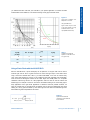
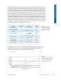
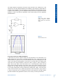
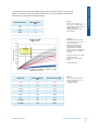
1
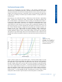
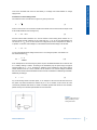
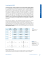
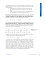
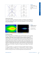
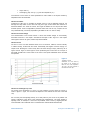
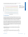
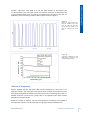
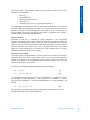
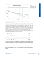
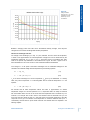
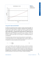
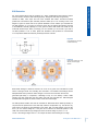
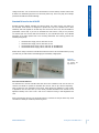
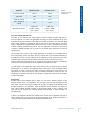
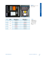
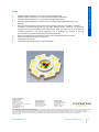
Driving the ACULED® VHL™ Introduction ® TM Excelitas’ new ACULED VHL , with its superior four-chip design and smallest footprint, gives customers the most flexible multi-chip LED on the market. The product family contains various products from UV via VIS to IR with a variety of chip configurations, including sensors and thermistors. Excelitas’ ACULED® DYOTM even enables customers to put together their own configuration. Please refer to the Custom Design Guide “ACULED DYO Design-Your-Own” for more details on this product. This application note describes the basics of electrical design for the ACULED and how to drive or adjust the colors of the different configurations of the ACULED VHL and ACULED DYO that can also be equipped with photodiodes and NTCs. www.excelitas.com Features and Benefits of the ACULED® VHL and DYO High power light, UV and IR source Ultra compact footprint Excellent color mixing due to high packaging density Separate anode and cathode for each color and pad Various standard configurations available Combination of LED with sensors Design-Your-Own (DYO) Author • Jörg Hannig Excelitas Technologies Luitpoldstrasse 6 85276 Pfaffenhofen Germany Phone: +49 8441 8917 0 Fax: +49 8441 71910 Email: [email protected] Technical Support • For additional technical support, please contact us at: [email protected] Applications General illumination Entertainment and shop design Furniture lighting Architectural and landscape lighting Mood lighting Vision systems Backlighting Medical lighting Display and signs Customized chip configuration Table of Contents General Remarks and Construction of the ACULED VHL 3 The Electrical Principle of LEDs 4 Connecting the ACULED 6 Influence of Current 9 Pulse Width Modulation 11 Influence of Temperature 12 Using an NTC with the ACULED DYO 16 Using a Photo Diode with the ACULED DYO 17 ESD Protection 21 Standard Drivers for the ACULED 22 Symbols and Units 25 Abbreviations 27 Notes 29 www.excelitas.com Driving the ACULED® VHL™ 2 General Remarks and Construction of the ACULED VHL The ACULED VHL board is based on an insulated metal core substrate (IMS) made from copper and a highly sophisticated isolation material with a low thermal resistance between the copper and chip pads. This package provides excellent heat dissipation and thermal management from the chip to the substrate’s backside. The thermal resistance Rth JB of the entire package is quite low, depending on the chip configuration. To dissipate the heat, adequate cooling must be considered. To avoid damaging the LED chips by overheating when equipped with at least one high-power LED chip, the ACULED must not run without appropriate cooling - even at lower currents. Figure 1 shows the typical layout of the ACULED VHL. The chips are placed in the middle of the board, protected by a PPA-based ring and silicone resin encapsulation. The latter is transparent and suitable for a wide range of radiation from ultraviolet (UV) to infrared (IR). It is also more resistant to heat than epoxy resin, and its heat expansion characteristics are closer to those of chips. With the ACULED’s high-power LEDs, silicone achieves superior resistance to light radiation, mitigating degradation, and maintaining LED color purity over the LED’s lifetime. The mechanical stress applied to the chips is lowest with silicone, as compared to standard encapsulation materials. Due to its softness, pressure to the silicone area within the ring must be avoided. Please refer to the application note “Handling of LED and Sensor Products Encapsulated by Silicone Resin” to learn more about handling silicone-based products such as the ACULED. The clockwise numbered pads C1 - C4 inside the encapsulation ring show the pads where the LED chips are placed. The distance between the chips is typically 0.2 mm with a pitch of 1.2 mm. Therefore, the lighting area is approximately 2.2 x 2.2 mm², depending on the particular chip configuration for the specific ACULED VHL or ACULED DYO product. The numbers of the soldering pads run counter-clockwise from pin 1 to pin 8. The pad numbers 4 and 5 are printed on the board. Pin 1 is easily located by the small gold dot, which can be used as a reference for mounting. Whether ESD protection diodes should be used depends on the ESD sensitivity of the LED chips and is referenced in the specific datasheets of the products. The tracks on the ACULED are made from copper with a thin gold layer to achieve better bonding results. Figure 1 Layout and Dimensions of the ACULED VHL. www.excelitas.com Driving the ACULED® VHL™ 3 The Electrical Principle of LEDs LED dies are semiconductors and hence different in their electrical characteristics from conductors such as incandescent light bulbs. In the latter the electrical resistance R will increase with rising temperature and thus with increasing electrical current, which gives a kind of limitation of the electrical current flow. The direction of the current usually does not matter. With a light bulb, by the heating of its filament, light is emitted as radiation in a large spectrum from mostly IR to blue. Semiconductors such as LED dies behave in a different way. As the name LED - Light Emitting Diode - indicates, light is emitted from a diode, a semiconductor chip doped with impurities. Like with a normal diode, the current direction and thus the polarity of its so-called forward voltage VF is given by the anode (positive doped side, p) and the cathode (negative doped side, n). The corresponding forward current IF flows from p to n, leading to a recombination of the charge carriers electrons (n) and holes (p) in the pn junction layer by emitting light. Depending on the band gap energy of the pn junction materials used, the spectrum of this light is UV, VIS or IR with a narrow bandwidth. Applying a voltage with wrong polarity does not light the LED but can damage the chip if the voltage exceeds the reverse breakdown voltage. Therefore this maximum reverse voltage VR that the chip can handle without damage is given in the specific ACULED datasheets. Placing a diode in inverse polarity parallel to the LED can also protect the LED against too high reverse voltage. With some of the ACULED VHLs and on demand with the ACULED DYO, bipolar ESD protection diodes are used that protect the device according to this principle. Figure 2 Typical current vs. voltage characteristic of an LED shown at the example of the ACULED VHL RGYB at 25°C board temperature. The color of the curves responds to the emitted color of the chips. Figure 2 shows the typical curve of the forward current IF versus the forward voltage VF at high power LED chips used with the ACULED VHL RGYB. We can see that even small changes of the voltage result in huge changes of the according forward current, at least in the region where the LED is typically driven (100 to 700 mA). Since most of the properties of interest like intensity and color of an LED depend on the current IF, it should be kept stable and controlled. We will learn in later chapters about the influence of IF on the LED parameters as well as methods to keep these parameters constant. When using a power source without constant current like a battery for example, we have to make sure that the current IF cannot exceed the maximum forward current IF max to avoid damaging the LED. The easiest way to do this is using a current limiting series resistor as shown in figure 3. Without a current limiting device, an LED product www.excelitas.com Driving the ACULED® VHL™ 4 such as the ACULED must never be used directly to a voltage source like batteries or voltage supply source. Calculation of current limiting resistor The resistance R of a circuit as shown in figure 3 is given by Ohm’s law R = V I (1) where I is the current in the circuit that is equal to the forward current IF that we want to adjust, and R is the overall resistance of the circuit given by R = RRL + RLED (2) with the internal LED’s resistance RLED and the wanted current limiting series resistor RRL. In practice usually the LED resistance is very small with RLED << RRL so as good approximation we can assume R ≈ RRL. Since in serial circuits the voltage drops at each component are added, V in equation 1 is the sum of the voltage VRL at the resistor and the forward voltage VF at the LED: V = VRL + VF (3) V in this case represents the voltage of the source VS. According to equation 1 this leads us to the wanted resistance RRL: RRL = V −V I (1a) F As an example let us assume driving the yellow chip from the RGYB ACULED VHL at 350 mA with a 9 V battery utilizing a resistor. According to the datasheet (only the yellow chip!) the typical forward voltage is VF = 2.2 V. According to equation 1a the resistance of the current limiting resistor needs to be 20 Ω or more. However, due to variations in the forward voltages of different dies, the same resistor will lead to different forward currents and therefore to different light intensities. Additionally, according to P = IV (4) any current limiting resistor consumes power, in our example 2.4 W which is three times more than the yellow chip itself! Therefore the easiest way is to use a constant current source like most commercially available LED drivers are made of. Excelitas provides LED drivers for the ACULED; please contact your local sales representative for more information. Figure 3 Battery Principle of LED-circuit using a battery and utilizing a current limiting series resistor. LED www.excelitas.com Resistor Driving the ACULED® VHL™ 5 Connecting the ACULED The electrical circuit of a specific ACULED VHL can be found in the specific datasheet. Figure 1 shows the layout with the chip pads called Cn and the eight electrical connections labelled Pin n. The assignment from the chip pads to the pins can be found in the ACULED datasheet for the ACULED VHL and in table 1 for the ACULED DYO. Figure 4 is showing an example that represents most of the visible ACULED VHLs. Please note that your specific ACULED VHL or DYO product can be different from this example, please refer to the datasheet. It is a big benefit of the ACULED VHL design that each LED chip can be driven individually, even if a chip type is used twice or more. This gives you the opportunity to drive the ACULED according to your needs, for example with one of the different four channel drivers provided by Excelitas. Please refer to the chapter later in this application note and to the driver datasheets for more information. If you want to connect the four chips serially, for example with a monochromatic ACULED VHL, you only have to connect neighboured pins as shown in figure 5. To learn more about mounting and soldering of the ACULED please refer to the application note “Mounting of the ACULED”. Please note that the ACULED is a highly sophisticated semiconductor product which is sensitive to electro-static discharge (ESD) and other current and stress peaks, though most of the ACULED VHLs have ESD protection diodes. Therefore when connecting the ACULED to a driver and PSU make sure to use a suitable device that does not show any start-up peaks which can damage the LED dies. Though a chip may not be damaged directly, even a very short current peak exceeding the maximum surge current IFM per chip can pre-damage the LED in a way that will dramatically decrease its lifetime. Pin 1 2 Chip position C4 3 4 5 6 C3 C2 7 8 C1 Polarity non IR chips Polarity Polarity IR chips PD chips anode (+) anode (+) cathode (-) anode (+) cathode (-) cathode (-) anode (+) anode (+) anode (+) cathode (-) cathode (-) anode (+) cathode (-) anode (+) anode (+) cathode (-) cathode (-) cathode (-) anode (+) anode (+) anode (+) cathode (-) cathode (-) cathode (-) Table 1 Typical assignment of chip positions to pins for the ACULED. Figure 4 Electrical circuit of the ACULED VHL and DYO. It shows the standard assignment of the pins to the chip pads Cn for most of the VHL products like the RGYB. Serial vs. parallel connection In figure 6, left side we can see the circuit of a parallel connection of the ACULED which is highly discouraged. LED chips should always be connected serially. The reason is the different www.excelitas.com Driving the ACULED® VHL™ 6 forward voltages VF of the chips on the one hand and the dependency of the temperature and other parameters of the dies from the current IF on the other hand. Please note the basic rules for parallel and serial connections: • • In parallel circuits, the voltage is the same in each track, whereas the current flow is divided according to the power consumption of the components in the tracks. In serial circuits, the current is the same in the line, whereas the voltage drop at each component depends on the power consumption of the component. Remember that LED chips are driven and thus controlled by the current flow. Driving chips serially as shown in figure 5 leads to the same current IF in each chip and therefore to a homogeneity in brightness and color. Small differences between the chips are represented in the different forward voltages of the chips. The overall voltage needed to drive a number of chips serially at a given current IF can easily be calculated by the following equation: n VF sum = VF1 + VF2 + VF3 + VFn = ∑ VFi (5) i =1 Please note that the forward voltage changes with the current and the temperature of the chip. When designing or looking for a power supply unit (PSU) to drive serially connected chips, be sure the voltage of the PSU is high enough, i.e. VF sum or higher, otherwise some LED dies may not emit light. Especially when connecting only small chains of LEDs serially, as for example the four chips of a monochromatic ACULED VHL, it is safer to calculate rather with the maximum as with the typical VF. Both values can be found in the ACULED datasheets. Figure 5 Circuit of serial connection of the ACULED VHL chips. In a parallel connection as shown in figure 6, the current will not be the same through all chips, but will depend on the forward voltage of each LED die in the specific track: n IF sum = IF1 + IF2 + IF3 + IFn = ∑I Fi (6) i =1 As we can see in figure 2, even small variations in the forward voltage, which is quite regular with LED chips even on one wafer, result in large changes in the forward current. Therefore, in a parallel circuit the currents IFi flowing in track i can be quite different, leading to inhomogeneous intensity and color and even damaging a chip once the forward current exceeds the maximum allowable value. But even if no damage occurs, the unwanted effects will increase over time: The chips with the higher current will get hotter than the others, resulting in lower forward voltages due to the negative temperature coefficient TCVF. This will again increase the current and therefore the temperature, etc. Even if not damaged, the LEDs will at least drift away in brightness and wavelength. Figure 7 shows this effect at a line of LED chips driven in parallel for a longer time. The higher the variation in the forward voltage, the faster the effects occur. www.excelitas.com Driving the ACULED® VHL™ 7 Figure 6 Left: Circuit of parallel connection of the ACULED VHL chips, which is highly discouraged. Right: Circuit with common anode. Common anode / cathode If the number of connections is limited and the ACULED is not cascaded with other ACULEDs (see next section), a common anode or cathode can be used. Figure 6, right side shows the diagram of such a circuit. Though each channel can still be driven individually, only five instead of eight connections have to be used. Figure 7 Temperature profiles taken by an IR camera for a line of parallelly driven LED chips. Left: After half a minute. Right: After a few minutes. Cascading the ACULED When connecting more than one ACULED of a kind, usually chips with the same color should be driven simultaneously. With the rules learned above, we now know that connecting the corresponding chips serially as shown in figure 8 is the best solution for constant and homogeneous color of each channel. According to equation 5, the forward voltages of the chips have to be added, so you have to take care that the PSU can provide the voltage needed. When cascading a larger number of ACULEDs or chips to be precise, the summary voltage VF sum can easily achieve high values. Therefore it can be helpful to make a cross connection after a couple of serially connected chips as shown in figure 9. This also adds some redundancy into the driving circuit, helping to leave some LEDs of a channel illuminated if a single chip fails during operation. It is recommended to have at least a minimum of four to five chips serially connected before adding a cross section to average over the different forward voltages of the individual LED chips. The power consumption PCn of a single chip can easily be calculated according to equation 4. To calculate the power consumption Ptot of a single ACULED or a bunch of connected ACULEDs, the individually PCn can be added up. This gives a hint of the minimum total power that a PSU must supply. The minimum current and voltage that has to be provided by the PSU www.excelitas.com Driving the ACULED® VHL™ 8 depends on the particular circuit. Remember that voltages have to be added in serial circuits and remain the same in parallel connection, whereas currents have to be calculated vice versa. Figure 8 Circuit diagram of cascaded ACULEDs. The corresponding chips of each color are connected serially. ACULED 1 ACULED 2 ACULED 3 ACULED 4 ACULED 5 ACULED 6 ACULED 7 ACULED 8 Figure 9 Mixture of parallel and serial connection of one ACULED channel to decrease ACULED 9 ACULED 10 ACULED 11 ACULED 12 ACULED 13 ACULED 14 ACULED 15 ACULED 16 VF sum and increase redundancy. Testing in laboratory There is a significant danger of destroying LED chips when testing them, for example in a laboratory environment. Beside the above mentioned issues of ESD and current overshoot of faulty drivers and PSUs, bad connections, for example with improperly soldered cables, can damage a chip due to the peak caused by a sudden circuitry interrupt. Make sure you have switched off the PSU any time you connect or disconnect the ACULED to it. When testing an LED with a constant current source, use a voltage limit to avoid voltage overshoot. In doubt you can start with a small voltage and increase it carefully to the value of the maximum forward voltage that is shown in the ACULED datasheet. Influence of Current As described in the previous chapter, LEDs are usually driven by current. Hence a constant LED light output requires a constant current source. Beside the necessity to avoid the chip from being damaged by overdriving, the current has an impact on several parameters which are particularly • • lifetime [tLife] forward voltage [VF] www.excelitas.com Driving the ACULED® VHL™ 9 • • flux [Φ e and Φ V] wavelength [λ] resp. color [x2° / y2°] and color temperature (TCT). The influence of the current on these parameters is often similar to the impact caused by temperature which we will see later. Influence on lifetime Overdriving an LED chip, i.e. exceeding its forward current IF over the allowable maximum, will damage the chips within a short time. But long term high current effects also influence a decreased lifetime: The lower the current, the longer the lifetime for the chip and the whole ACULED product. Since the degradation processes behind this truth are very complex and not fully understood today, it is virtually impossible to get reliable curves of tLife versus IF today. Influence on forward voltage The characteristics of the forward current IF versus the forward voltage VF were already discussed and shown in the chapter “The Electrical Principle of LED”. Figure 2 in this chapter shows typical curves for red, green, and blue chips of the ACULED. Influence on flux The flux Φ e and Φ V and their deducted values, such as luminance, radiance, luminous intensity or radiant intensity, increase with the current. Unfortunately this happens not linear. Saying it in simple words: Doubling the current usually does not double the light output, particularly not at higher currents. Figure 10 shows typical curves representing the luminous flux for the chips of the RGYB ACULED VHL. These charts can be found in the specific datasheets of the ACULED VHL products. Figure 10 Typical flux vs. current characteristic of an LED shown by the example of the ACULED VHL RGYB at 25°C board temperature. The color of the curves responds to the emitted color of the chips. Influence on wavelength resp. color The change of the wavelength (λpeak resp. λdom) and, therefore, the color versus the current, is shown in figure 11. Again, it is not linear and depends on the material and the color of the LED chip. We can easily see that adjusting intensity of an LED product by the current is very difficult and needs a calibration of the driver to the individual chip characteristics. The same applies to adjusting colors, for example in a multi color chip ACULED, which is done by weighting the ratio of the intensities of each individual color to a wanted mixture. All these effects described here www.excelitas.com Driving the ACULED® VHL™ 10 show that driving the ACULED by changing the current is not a suitable solution. A much better way is to use pulse width modulation which will be explained in the next chapter. Figure 11 Typical wavelength vs. current characteristic of an LED shown by the example of the ACULED VHL RGYB at 25°C board temperature. The color of the curves responds to the emitted color of the chips. Pulse Width Modulation We have learned from the previous chapters that a stable LED in terms of life time, color or intensity needs a stable forward current as provided by constant current sources. But how can the intensity being dimmed without changing the current? The most common way is to use pulse width modulation (PWM). With PWM the LEDs are not driven in continuous but pulsed mode at a high repetition rate / frequency fPWM . Since this is in the region of some kilohertz and thus much above the flicker fusion threshold of the human eye, it will be seen as a continuous light. The trick is that PWM pulses switch from off (0 mA) to on (e.g. 350 mA) only and the duty cycle, i.e. the ratio of the on-time tP (pulse width) to the full time of a pulse period, gives the intensity of the LED. No currents in between these extreme values are used and therefore all current dependencies are almost obsolete. Figure 12 shows the principle of PWM. The “area” of a pulse given by its width tP at a fixed height corresponds to the intensity of the driven LED. By changing the width of the pulses (modulation) the LED brightness can be changed easily without the impacts of a changing current. The basic relation between the flux Φ, duty cycle dPWM and pulse width is proportional in first approximation: Φ ~ dPWM ~ tP (7) Nevertheless temperature effects also occur with PWM since the heating of an LED chip is caused by the power it consumes. This is given by equation 4 which must be modified when using PWM in the following way: Ptot = dPWM IF PWM VF (4a) IF PWM represents the forward current given by the PWM source which must not exceed the maximum forward current IF max of the LED, whereas dPWM represents the duty cycle given by dPWM = tP fPWM www.excelitas.com (8) Driving the ACULED® VHL™ 11 Excelitas ’ LED drivers utilize PWM for a safe and stable operation of the ACULED VHL and DYO products. In the next chapter we will learn about the influence of the temperature. Due to the temperature effects on the one hand and non-perfect slope of the pulses on the other, the dependency of the flux according to relation 7 differs in practice as shown in figure 13. Figure 12 current Principle of PWM: Square wave pulses are modulated in their duty cycle. The “wider” the pulses and thus the longer the on-time tP, the higher the intensity of the driven LED. time low intensity mid intensity Max. junction temp: 125°C typical green LED (520nm) Duty cycle D=tP/T: 240 Radiant flux Φ e [mW] high intensity 220 200 Figure 13 Dependency of radiant flux Φe from pulse width tP at a given duty cycle with the ACULED green chip. 0,5 0,25 0,1 0,05 180 160 140 120 100 80 60 40 20 1 2 3 4 5 6 7 8 9 10 Pulse width tp [ms] Influence of Temperature With the ACULED and other high power LEDs, thermal management is a main issue in any application since 60 - 90% of the power consumed will still be converted into heat rather than light. When driving the ACULED, this heating must be taken into account to avoid damage to the LED. For detailed information concerning this, please refer to the application note called “Thermal Management of the ACULED VHL”. Beside the necessity to avoid the chip from being damaged by overheating, the knowledge of the temperature impacts on the LED chips helps us to get a grip on these parameters when www.excelitas.com Driving the ACULED® VHL™ 12 driving the ACULED. The parameters influenced by temperature are quite similar to those impacted by current, particularly • • • • • lifetime [tLife] forward voltage [VF] maximum forward current [IF max] flux [Φ e and Φ V] wavelength [λ] resp. color [x2°/ y2°] and color temperature (TCT). A big advantage of the ACULED VHL and DYO versus other similar products on the market is minimized thermal crosstalk between the pads. For more information please refer to the application note called “Thermal Management of the ACULED VHL”. As a result of this low thermal crosstalk, the warming of one LED has minimal affect on neighboring chips, resulting in excellent constancy in the parameters described above. Influence on lifetime Overheating an LED chip, i.e. exceeding its junction temperature TJ over the allowable maximum, will damage the chips within a short time. But long-term temperature effects also influence a decreased lifetime. During operation, the lower the temperature, the longer the lifetime for the chip and the whole ACULED product. Some degeneration processes require a minimum temperature to get started. Thus, a low TJ will dramatically increase the product’s lifetime. Since these processes are very complex and not fully understood today, it is virtually impossible to get reliable curves of tLife versus TJ today. Influence on forward voltage The forward voltage VF usually decreases in the range of several mV per Kelvin with increases in temperature. Since this change in approximation is linear over the typical small temperature changes, it is provided in the temperature coefficient of forward voltage TCVF found in the ACULED VHL datasheet or the chip datasheets of the ACULED DYO chips. Figure 14 shows typical curves for red, green, and blue chips. The change ∆VF of the forward voltage is calculated by the following equation: ∆VF = TCVF ∆TJ VF1 = TCVF (TJ1 - TJ0) + VF0 (9) (9a) VF1 is the forward voltage that we want to calculate at a temperature TJ1, whereas VF0 is a known forward voltage at a known temperature TJ0, e.g. values given by the datasheets. In a steady state, the junction temperature TJ and the substrate temperature TB are interchangeable in the equation: VF1 = TCVF (TB1 - TB0) + VF0 (9b) With a decrease of the forward voltage, power consumption drops as well at a given current. But due to the small change, it is of no practical significance. www.excelitas.com Driving the ACULED® VHL™ 13 Figure 14 Relative Forward Voltage Relative forward voltage VF versus ACULED VHL board temperature TB for red, green and blue chips. 1,06 1,04 VVV F / VF (25°C) 1,02 1 0,98 0,96 0,94 0,92 10 20 30 40 50 60 70 80 T B [°C] Influence on flux and intensity The flux, Φe and ΦV , and their deducted values, such as luminance, radiance, luminous intensity or radiant intensity, decreases with increasing temperature. Generally speaking, the intensity drop of blue and green chips is usually small, whereas the drop with yellow, amber and red chips is larger. Figure 15 shows typical curves representing the relative luminous drift for the chips of the RGYB ACULED VHL. These charts can be found in the specific datasheets of the ACULED VHL products. For the ACULED DYO, an approximation is given by the luminous or radiant flux temperature coefficient (TCΦV resp. TCΦe) in the specific datasheets of the chips. The change ∆Φ of the luminous or radiant flux can be calculated analogous to the calculation of the forward voltage drift over temperature by the following equation: ∆Φ = TCΦ ∆TJ Φ1 = TCΦ (TJ1 - TJ0) + Φ0 (10) (10a) Φ 0 is the known flux at a known temperature TJ0 given by the datasheets. In a steady state, the junction temperature TJ can be interchanged with the substrate temperature TB in the equation: Φ1 = TCΦ (TB1 - TB0) + Φ0 (10b) If a certain flux is necessary in your application, it is important to level out the intensity drop. A good thermal management will also help you keep the drift as low as possible. The balancing of the drift over temperature is important, particularly when having chips of different colors on your ACULED like RGGB or RGYB, to keep the same intensity ratio and, therefore, the same color appearance. With the RGYB for example, the color mix drifts to a blue-greenish light with increasing temperature, since yellow and red fade out much more than blue and green, as shown in figure 15. Due to the excellent suppression of any thermal crosstalk, each chip can be levelled out individually without regard for how its temperature and heating change influence its neighbors. www.excelitas.com Driving the ACULED® VHL™ 14 Figure 15 Relative Luminous Flux = f(T B) Change of relative luminous flux ΦV vs. board temperature TB for the RGYB chips of the ACULED VHL. 140,00 130,00 120,00 in % 90,00 / 100,00 25°C 110,00 80,00 70,00 60,00 50,00 40,00 10 15 20 25 30 35 40 45 50 55 60 65 70 75 80 T B [°C] Besides a changing mixed color ratio due to the different intensity changes, each chip also changes color as a result of wavelength drift caused by temperature. Influence on wavelength and color The change of the wavelength (λpeak resp. λdom) and, therefore, the color versus the temperature, is linear in first approximation at small temperature changes and can be determined by the temperature coefficients TCλ peak and / or TCλ dom. These are found in the ACULED VHL datasheet or the specific chip datasheets of the ACULED DYO. Figure 16 shows a typical curve of the IR ACULED VHL. This curve is shown in each individual ACULED VHL datasheet. The change ∆λ of the peak or dominant wavelength can be calculated analogous to the calculation of the forward voltage drift over temperature by the following equation: ∆λ = TCλ ∆TJ λ1 = TCλ (TJ1 - TJ0) + λ0 (11) (11a) λ0 is the known wavelength at a known temperature TJ0 given by the datasheets. In a steady state, the junction temperature TJ is interchangeable with the substrate temperature TB in the equation: λ1 = TCλ (TB1 - TB0) + λ0 (11b) We learned that all these temperature effects are linear in approximation for smaller temperature changes. So with the equations 9 to 11, temperature drifts can easily be balanced with the ACULED driver. But how do we know about the temperature drift? A sufficient way is to measure it, for example with an NTC close to the ACULED. With the ACULED DYO you can even have the NTC inside the ring on a chip pad which is the closest placement to the LED chips that one can get. The influence of the temperature on the NTC resistance itself (R vs. T characteristic) and the effect on photo diodes used with the ACULED DYO are explained in the following chapters. www.excelitas.com Driving the ACULED® VHL™ 15 Figure 16 Peak wavelength λ peak = f(T B) Change of peak wavelength λpeak vs. substrate temperature TB for the IR ACULED VHL. 875,0 870,0 peak [nm] 865,0 860,0 855,0 850,0 845,0 10 15 20 25 30 35 40 45 50 55 60 65 70 75 80 T B [°C] Using an NTC with the ACULED DYO The safest way of controlling the heat is to measure it. As shown in the previous chapter, we can do this by controlling TB since we can calculate the corresponding junction temperature TJ of the used chips. The board temperature is measured by thermistors, as negative temperature coefficient resistors (NTCs), close to the ACULED’s board. The ACULED DYO allows you to even put an NTC chip on one pad of the ACULED to easily control the temperature close to the chips. The temperature TNTC inside the NTC is nearly the same as TB. Please refer to the application note “Thermal Management of the ACULED VHL” to see how to calculate the temperatures with NTCs. The height of the NTC-Chip used with the ACULED is very low and thus does not shadow the LED chips in any way, resulting in an undisturbed light emission of your ACULED DYO. The principle of an NTC is the change of its internal ohmic resistance RNTC with the temperature T. As the name indicates, RNTC(T) is a typically negative function, as shown in Figure 17. Its nominal resistance is 10 kΩ at 25 °C with 5% tolerance. By measuring the ohmic resistance we can now easily find the according board temperature by the following equation: TB R NTC = - cT ln c R (12) CT and CR are coefficients, whose values depend on the current IF used with the ACULED as shown in figure 17. The reason for the change of these coefficients with the current and thus with the temperature of the chips is the temperature drift from the chip pads where the NTC is placed to the ACULED back side. Please refer to the application note “Thermal Management of the ACULED VHL” for more information. In table 2 you can find typical values of the coefficient for different currents. If you want to be on the safe side, you should use the coefficients given for three chips at the maximum current you want to use. However, it is highly recommended that www.excelitas.com Driving the ACULED® VHL™ 16 you calibrate the NTC used with your ACULED in your specific application. To achieve accurate measurements of the resistance, a four-terminal sensing circuitry (4T) is the best choice. 20 Figure 17 18 Typical curve of resistance R vs. temperature T of an NTC: 16 Left: typical SMD NTCs. 14 Right: ACULED chip level NTC in the typical ACULED TB range for different currents IF of the chips (RGBN-ACULED DYO). RNTC [kΩΩ] 12 10 8 0 mA 6 4 700 mA 2 0 10 20 30 40 50 60 70 80 T B [°C] IF [mA] per Chip No. of Chips cT [°C] cR [kΩ] 0 0 26.3 25.6 700 1 21.8 26.4 700 3 22.3 26.3 Table 2 Coefficients to be used with equation 12 to calculate TB from RNTC (given in kΩ). Using a Photo Diode with the ACULED DYO With the ACULED DYO, a photo diode (PD) can be placed on a chip pad. PDs can be used to measure light and are hence a good instrument to control the light output of the LEDs. When using a multi-color ACULED with a PD, e.g. an ACL01-OD-RGBP, it can even be used for easy color control and adjusting by turning on and measuring each LED separately and sequentially. This can be done during the off-time of the other chips at a PWM pulse or in a specific calibration mode during off-hours of a lamp application. PDs can also be used to measure the ambient light, for example to switch on and off the ACULED according to the surrounding light in lamp applications. Also, light barrier applications in reflection mode are possible. However, we need to consider that no optical barrier is between the PD and the neighbored LED chips leading to a strong optical crosstalk by both direct light from the LEDs and reflected light from the ACULED ring and encapsulation-to-air surface. Figure 18 Symbol and reverse biased connection of a photo diode with the ACULED VHL. VR = -5 V Pin 1, 3, 5 or 7 www.excelitas.com Pin 2, 4, 6 or 8 Driving the ACULED® VHL™ 17 Figure 18 shows the principle of how to drive the PD with the ACULED. The standard PD that is used with the ACULED DYO is a silicon-based PIN-type photo diode and thus should be driven at a reverse bias voltage of VR = -5 V. This voltage has nearly no influence on the photo current but on the bandwidth in fast transient applications. Please note that the cathode of the PD is on the even numbered pads whereas with most of the LED chips the cathode is on the ACULED’s odd pads. Depending on the light captured by the PD, a photo current IPh flows, caused by the photons absorbed in the pn-junction. Even without any light, a small current called dark current ID can be measured. Among others it is caused by background radiation and has to be considered for calibration. Table 3 shows the typical characteristics of the PD used with the ACULED. The height of the PD-Chip is similar to the height of the LED chips and thus does not shadow the LED chips much, resulting in an almost undisturbed light emission of your ACULED DYO. Figure 19 shows the typical photo current IPh of the ACULED PD as a function of the luminous flux Φ V emitted from a chip placed on the ACULED. Parameter Symbol Condition Value Table 3 Electro-optical characteristics of Reverse dark current ID VR = - 5 V; Ee = 0 W/m² < 10 nA Reverse breakdown voltage VBR IR = 100 µA; Ee = 0 W/m² 170 V Open circuit voltage VOC TCT = 3000 K Ee = 50 W/m² 440 mV Photo current IPh VR = - 5 V; TCT = 3000 K Ee = 50 W/m² 7 µA Total capacitance CPD VR = - 5 V; Ee = 0 W/m² Series resistance RPD Turn-on/off time ton / toff the ACULED photo diode at TB = 25 °C. The currents are shown in absolute (positive) values. 10 pF 150 Ω =-5V VR = - 5 V; = 100 VR Ω RL 10 / 10 ns Due to the small photo current in the order of magnitude of some µA usually an amplifier is used with PDs. Figure 20 shows a typical circuit using operational amplifiers to convert the photo current IPh to an output voltage VOut according to the following equation: = RN IPh VOut (13) Figure 19 4000 Dependency of the photo current IPh from the luminous flux ΦV at a specific color at board temperature TB of 25°C on the ACULED DYO. Photocurrent IPh [µA] 3500 3000 2500 2000 IPh is pictured positive; VR = - 5 V. 1500 1000 500 0 0 5 10 15 20 25 30 35 40 45 50 luminous flux Φ V [lm] www.excelitas.com Driving the ACULED® VHL™ 18 The output voltage is proportional to the photo current and thus to the irradiance Ee or the illuminance EV at a given spectral distribution of the radiation or light reaching the photo diode; an example is given in table 4. Since the sensitivity of a PD depends on the wavelength as shown in figure 21, the resistance RN has to be adjusted according to the amount of light and its spectral distribution. To learn more about the amplification circuitry of PDs, please refer to the appropriate published literature. Figure 20 RN Typical circuitry utilizing operational amplifiers (op-amps) as current-tovoltage converter with reverse biased voltage VR. IPh + VOut VR + Figure 21 Spectral sensitivity of the PD. Using a photo diode with an RGBP ACULED DYO In this section we will see a specific example how the photodiode can be used based on an RGBP ACULED DYO, which means an ACULED equipped with a red, a green and a blue LED chip and the PD. In figure 22 we can see how the photo current of the PD depends on the current of the LEDs and the temperature of the board. The red LED leads to the highest photo current due to the spectral sensitivity of the PD as shown in figure 21 with its maximum at approx. 850 nm (IR). Table 5 shows the numbers at 25 °C board temperature. Please note that these numbers and figures depend on the intensity ranks of the specific ACULED and are for example only. The results were taken without any environmental light, so an important question is how these measurements would be influenced by ambient light. Table 4 shows the photo current of the PD induced only by ambient light typically for office illumination to get a picture of it. Since the values are very low compared to the photo current induced by the LEDs, ambient light does not matter in many applications. However, if it is an issue, you should synchronize the www.excelitas.com Driving the ACULED® VHL™ 19 PD measurement to the LED drive (PWM) signal to know the amount of light coming from the ambient and ambient plus LED. By signal processing you can easily subtract the environmental influence from your PD signal to get the pure LED light. Illuminance EV [lx] Table 4 Photo Current IPh [µA] 500 -4 1000 -8 2000 - 16 Photo current of PD @ VR = - 5 V induced only by ambient light of a certain illuminance at the ACULED. A CAL-2000 Mercury Argon calibration light source was used for the illumination. Figure 22 ACULED DYO RGBP PD @ V R = -5V Dependency of the photo current IPh from the color, the LED chips’ current IF and the board temperature TB on the ACULED DYO. Though the PD is nearly independent fromTB, temperature effects occur due to its influence on the intensities and wavelengths of the LEDs. 8000 7000 increasing temperature TB = 10 - 80 °C Photo Current IPh [µA] 6000 5000 Red, green and blue curves: single chips (red, green, blue). Black curves: all chips (RGB) together. 4000 3000 2000 IPh is pictured positive. 1000 0 0 200 400 600 800 1000 LED Forward Current I F [mA] LED [color] Current IF [mA] per LED Photo Current IPh [µA] Red 350 - 1740 Red 700 - 3320 Green 350 - 430 Green 700 - 680 Blue 350 - 580 Blue 700 - 970 All (RGB) 350 - 2900 All (RGB) 700 - 5100 www.excelitas.com Table 5 Photo current of a PD placed in an RGBP ACULED DYO at TB of 25 °C. These numbers correspond to figure 22. Driving the ACULED® VHL™ 20 ESD Protection We have learned before that the ACULED is a highly sophisticated semiconductor product which is sensitive to electro-static discharge (ESD). Though all LED chips are generally sensitive to ESD, some chips are even more sensitive than others. Therefore Excelitas protects the most sensitive chips with ESD protection diodes up to 2 kV according to the circuit diagram in figure 23. Please refer to the specific datasheet to check whether your ACULED VHL has ESD protection or not. Figure 24 shows the layout with and without these diodes according to the datasheet. Generally speaking UV, blue, green and white LEDs made from InGaN are the most ESD sensitive chips. When you design your own ACULED you can choose if you want to use ESD protection or not. In doubt, please ask Excelitas if ESD protection is recommended or not. If protection diodes are used, they are always at all four channels. Figure 23 LED - + Circuit diagram of the ACULED Z-diode and LED chip. Z-Diode Figure 24 Layout of the ACULED VHL / DYO with (left) and without (right) Z-diodes. Electrostatic damage to electronic devices can occur at any point from manufacture to field service. Damage results from handling the ACULED in uncontrolled surroundings without adequate ESD control practices. Static charges of 2 kV are not uncommon and can be generated quite easily. In comparison, a discharge of only 10 V can destroy a Class 1 ESD sensitive chip like InGaN dies that are widely used with the ACULED VHL. ESD damaged ACULED LEDs can appear dim, dead, shorted, or with low forward voltage. The ESD protection diodes used with the ACULED are bidirectional Zener diodes (Z-diodes) on chip level that are placed close to the LED chips inside the encapsulation ring. The dies are very small and do not disturb the light distribution of the LEDs. With a reverse leakage current of less than 1 µA at a reverse voltage of 5 V they also do not influence the electrical operation of the LEDs. The reverse break through voltage (also known as Zener voltage VZ) is 8 V ± 1 V at 10 mA. If the voltage is higher than VZ - for example at electro-static discharge or too high www.excelitas.com Driving the ACULED® VHL™ 21 voltage of the PSU - the current flows over the Z-diode but not the LED chip. Please note that the Z diodes can withstand high power for a short time period only. This is why they do not always prevent the ACULED from electrical damage. Standard Drivers for the ACULED Excelitas provides different standard four-channel drivers and power supply units (PSU) for the ACULED. These drivers are designed to operate each chip of an ACULED VHL or DYO individually and work together for all LED chips from UV via VIS to IR. They are not suitable for photodiodes or NTC chips. If you have an ACULED DYO with an NTC or PD you can just leave one channel open and use the other three channels for your ACULED LED chips. For a detailed description of the PSUs please refer to the according datasheets. The following products are available (see figure 25): • • • • ACULED Power Supply; 350 mA; PSU-ACL-01-350 ACULED Power Supply; 700 mA; PSU-ACL-01-700 ACULED DMX Power Supply; 350 mA; PSU-ACL-01-350 DMX 220V ACULED DMX Power Supply; 700 mA; PSU-ACL-01-700 DMX 220V Please note to always connect the ACULED to the PSU first and turn off all switches before you plug your PSU into your wall socket to avoid damaging the ACULED by voltage peaks. Figure 25 ACULED drivers: Left: Standard PSU. Right: DMX PSU. Four-Channel PSU LED driver The standard four channel ACULED PSU LED drivers are available as 350 mA and 700 mA versions and suitable to operate the ACULED with 350 mA 700 mA per channel respectively . Table 6 shows the main parameters of the PSUs. These drivers are suitable for a large variety of applications and can even drive up to five serially cascaded ACULEDs. Each channel can be adjusted manually from 0 mA to 350 / 700 mA for continuous tuning of LED brightness and color. When connecting the driver to your wall socket use the L connection for line (US: black wire), the N connection for neutral (US: white wire) and PE for ground. www.excelitas.com Driving the ACULED® VHL™ 22 Parameter PSU-ACL-01-350 PSU-ACL-01-700 Current per channel 350 mA 700 mA Total power 16 W 38 W Power per channel 4W 9.5 W 11.4 V 13.5 V 5 (Red - IR) 4 (Yellow - Amber) 3 (UV - Green) 5 (Red - IR) 4 (Yellow - Amber) 3 (UV - Green) Max. voltage per channel Max. LED per channel Table 6 Overview over ACULED standard PSUs. Four-Channel DMX PSU LED driver According to the DMX-512 light communication protocol Excelitas provides DMX PSU to drive the ACULED. The serial and digital DMX technology has been established as the most important transmission standard in the stage and theater environment. The ACULED DMX Power Supply product line is available as 350 mA and 700 mA four-channel drivers. The power supply is equipped with integrated DMX interface and hence is used in professional light control of LEDs, especially ACULED family products. The main application of the device is color mixing of RGYB- or RBGW-ACULEDs, but any other kind of ACULED DYO combination can also be operated easily. The automatic color change in color mixing applications is controlled via an integrated device with corresponding options. The device has four channels that can be activated separately by the DMX-512 protocol. The start address can be adjusted by coding switches that are easily accessible. With a maximum total output power of 30 W per channel for the 700 mA version or 15 W per channel for the 350 mA version, a constant current of 350 mA or 700 mA is available per channel. Thus up to twelve ACULEDs can be operated with four different channels. If a DMX signal is not available, the control of the LEDs can also be carried out by four external potentiometers or by means of the integrated device. Several color cycles with different speed are feasible. A master / slave function allows synchronous operation of several devices. The LED outputs are short-circuit-proof. By means of additional temperature measuring input, the temperature of the PCB of the LED can be controlled. The DMX PSU LED drivers are available for 220 V input voltage. Designer Kits Excelitas offers various Designer Kits to easily run and test the different products of the ACULED product family in your application. They are easy to use and ready-to-operate in a few quick steps. Test and see how the Designer Kit can help you assess the functionality of the ACULED products in your application. There are different versions available, but all have at least a PSU, different ACULEDs mounted on through-looking PCBs for easy connection, heat sinks and tools for assembly and mounting. Please contact Excelitas for more information on the Designer Kits. In table 7 the assignment between the ACULED PSU channels and the ACULED chip pads is shown. Please refer to the manuals of the specific designer kit for detailed information on connection and driving the ACULED with the equipment provided by the kit. www.excelitas.com Driving the ACULED® VHL™ 23 Figure 26 ACULED Designer Kit for easy testing of ACULEDs. Pin 1 2 3 4 Chip position C4 C3 5 6 7 8 C2 C1 www.excelitas.com PSU channel VIS ACULED VHL Channel 3 - PSU channel IR ACULED VHL Channel 4 + Channel 3 + Channel 4 - Channel 2 - Channel 1 + Channel 2 + Channel 1 - Channel 1 - Channel 2 + Channel 1 + Channel 4 - Channel 2 Channel 3 + Channel 4 + Channel 3 - Table 7 Assignment of chip positions to the channels of the PSU as used with the ACULED Designer Kits. The red wire indicates Channel 1 +. Driving the ACULED® VHL™ 24 Symbols and Units The following terms and their typical units are used in the application notes and datasheets of the ACULED. Please note that not all of these are used in this particular note. A [m²] area, surface Arad [mm²] radiating surface Cn [-] chip pad number n in the ACULED CPD [pF] capacitance of PD cR [kΩ] coefficient used for NTC calculation cT [°C] coefficient used for NTC calculation dPWM [%] duty cycle PWM Ee [W/m²] irradiance EV [lx] illuminance [lux] fPWM [Hz] frequency of PWM pulses Φe [mW] radiant flux ΦV [lm] luminous flux [lumen] ID [nA] dark current of PD Ie [W/sr] radiant intensity IF [mA] forward current IF PWM [mA] forward current used with PWM IF sum [mA] summary forward current of parallel connected LED chips IFM [mA] surge current IPh [µA] photo current of PD IR [µA] reverse current IV [cd] luminous intensity [candela] Le [W/(m²sr)] radiance LV [cd/m²] luminance ∆λ [nm] spectral half bandwidth (usually FWHM) λdom [nm] dominant wavelength λpeak [nm] peak wavelength η [%] efficiency ηopt [lm/W] optical (luminous) efficacy PCn [W] power consumption of chip placed on pad n of the ACULED Popt [mW] output power (optical) Ptot [W] power consumption (electrical) [Watt] R [Ω] (electric) resistance www.excelitas.com Driving the ACULED® VHL™ 25 Ra [-] CRI (average value of testing colors R1 to R8) RLED [Ω] (internal) LED resistance RNTC [Ω] NTC resistance (function of T) RPD [Ω] series resistance of PD RRL [Ω] current limiting resistance Rth [K/W] thermal resistance (general) [Kelvin per Watt] Rth BA [K/W] thermal resistance from base (B) backside to ambient surrounding (A) Rth JA [K/W] thermal resistance from junction (J) to ambient air or surrounding (A) Rth JB [K/W] thermal resistance from junction (J) to base (B) backside RH [%] relative humidity T [°C] or [K] temperature (general) t [s] time TA [°C] ambient temperature TB [°C] base temperature on back side of package (substrate) TCT [K] (correlated) color temperature TJ [°C] junction temperature tLife [h] life time of LED chip or module TNTC [°C] temperature inside NTC chip Top [°C] operating temperature tP [s] on-time at PWM pulse representing the pulse width Tsold [°C] soldering temperature (at backside of the ACULED VHL) Tst [°C] storage temperature ∆TBA [K] difference between base and ambient temperature ∆TJB [K] difference between junction and base temperature [Kelvin] ∆TJA [K] difference between junction and ambient temperature TCΦe [mW/K] temperature coefficient of radiant flux TCΦV [mlm/K] temperature coefficient of luminous flux TCλ dom [nm/K] temperature coefficient of dominant wavelength TCλ peak [nm/K] temperature coefficient of peak wavelength TCVF [mV/K] temperature coefficient of forward voltage VBR [V] breakdown voltage VF [V] forward voltage VF sum [V] summary forward voltage of serially connected LED chips VOC [mV] open circuit voltage of PD VOut [V] output voltage www.excelitas.com Driving the ACULED® VHL™ 26 VR [V] reverse voltage VRL [V] voltage at current limiting resistor VS [V] voltage of (constant voltage) source or battery VZ [V] Zener or break through voltage of Z-diode xn° [-] x coordinate in CIE color space for n-degree observer (usually n = 2 is used with light sources like LEDs: x2°) yn° [-] y coordinate in CIE color space for n-degree observer (usually n = 2 is used with light sources like LEDs: y2°) 2ψ [°] viewing angle (usually at half of maximum intensity) Abbreviations The following abbreviations are used in the application notes. Please note that not all of these abbreviations are used in this particular note. ACULED® The trademarked name for Excelitas’ range of All Color Ultrabright LEDs. BOM Bill of Material ccw counter clockwise CCT Correlated Color Temperature CIE Commission Internationale de l'Eclairage = International Commission on Illumination COB Chip-on-Board CRI Color Rendering Index, value to measure the quality of light used for illumination purposes. DMX Digital Multiplex, serial light communication protocol (DMX-512) DYOTM Design-Your-Own, indicates an ACULED with customized chip configuration DUT Device Under Test ESD Electro Static Discharge, Electro Static Damage, Electro Static Sensitive Device FR4 Flame resistant 4, low cost PCB material made from epoxy resin and fiberglass mat FWHM Full Width at Half Maximum IMS Insulated Metal Substrate, PCB substrate made from aluminum or copper to provide excellent heat management IR Infra Red, radiation above 700 nm within the scope of this application note LED Light Emitting Diode NTC Negative Temperature Coefficient, used as acronym for an NTC resistant. Thermistor to control (LED-) temperature PCB Printed Circuit Board PD Photo Diode www.excelitas.com Driving the ACULED® VHL™ 27 PIN diode Positive Intrinsic Negative diode; diode with undoped intrinsic semiconductor between positive (p) and negative (n) regions PMMA Polymethyl methacrylate, transparent thermoplastic; in optical grade used for lenses pn junction Layer in the LED chip, where positive (p) and negative (n) charged carriers recombine to light respectively radiation. PPA Polyphtalamide (plastic) PSU Power Supply Unit PT100 Thermistor made from platin with 100 Ω at 0 °C. Has a Positive Temperature Coefficient (PTC). PWM Pulse Width Modulation SMD Surface Mount Device TIM Thermal interface material UV Ultra Violet, with LEDs radiation below 405 nm within the scope of this application note VHLTM Very High Lumen. This is the name for the newest generation of standard monochromatic and multi-colored 4-chip ACULEDs. VIS Visible light, radiation between 405 and 700 nm within the scope of this application note Zener Diode, usually used as ESD protection Z-diode www.excelitas.com Driving the ACULED® VHL™ 28 Notes 1. 2. 3. 4. 5. 6. 7. 8. 9. Excelitas maintains a tolerance of ± 5% on flux and power measurements. Excelitas maintains a tolerance of ± 2 nm for dominant wavelength measurements. Excelitas maintains a tolerance of ± 1 nm for peak wavelength measurements. Excelitas maintains a tolerance of ± 2 K/W for thermal resistance measurements depending on chip properties. Due to the special conditions of the manufacturing processes of LEDs, the typical data or calculated correlations of technical parameters can only reflect statistical figures. These do not necessarily correspond to the actual parameters of each single product, which could differ from the typical data and calculated correlations or the typical characteristic line. If requested, e.g. because of technical improvements, these typ. data will be changed without any further notice. Proper current derating must be observed to maintain junction temperature below the maximum. LEDs are not designed to be driven in reverse bias. All drawings are not to scale. All dimensions are specified in [mm] if not otherwise noticed. North American Sales Office Excelitas Technologies 35 Congress Street Salem, MA 01970, USA Telephone: +1 978-745-3200 Toll free: (North America) +1 800-950-3441 Fax: +1 978-745-0894 [email protected] www.excelitas.com European Headquarters Excelitas Technologies Wenzel-Jaksch-Str. 31 65199 Wiesbaden, Germany Telephone: (+49) 611-492-269 Fax: (+49) 611-492-170 Asia Headquarters Excelitas Technologies 47 Ayer Rajah Crescent #06-12 Singapore 139947 Telephone: (+65) 6775-2022 Fax: (+65) 6775-1008 For a complete listing of our global offices, visit www.excelitas.com ©2011 Excelitas Technologies Corp. All rights reserved. The Excelitas logo and design are registered trademarks of Excelitas Technologies Corp. ACULED®, VHL™, DYO™, and the LED Solutions logo are trademarks of Excelitas Technologies Corp. or its subsidiaries, in the United States and other countries. All other trademarks not owned by Excelitas Technologies Corp. or its subsidiaries that are depicted herein are the property of their respective owners. Excelitas reserves the right to change this document at any time without notice and disclaims liability for editorial, pictorial or typographical errors. 600250_01 APP0308 www.excelitas.com Driving the ACULED® VHL™ 29
![[Competition Commission Undertaking No [ ] of 2004]](http://vs1.manualzilla.com/store/data/006010311_1-21996dba8872f587e5a78ef073ded048-150x150.png)