1
The Hot-One System
Standard Hot-One system
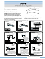
Gate Mate 4TM nozzles
Types - GMB
SCH TCG GMB
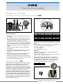
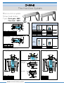
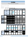
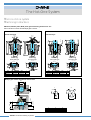
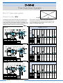
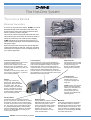
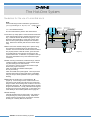
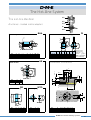
The Gate Mate 4TM nozzle is used under a hot manifold and is ideal for fast-cycling multi-cavity molds and
thin walled parts. Its compact design permits
centerline-to-centerline distances for use in smaller
molds, or increased cavitation in larger molds.
Thermocouple placement provides better heater
control and the overall nozzle design gives improved
thermal insulation.
GMB
GMT SCH
GMB
TCG
EHR
EHR
Heater, thermocouple and tip are both replaceable.
The Gate Mate 4TM is available in a wide variety of
lengths and can be fitted with five different tip styles,
allowing a great flexibility in applications, with most
types of plastic materials and a broad range in molding weight.
SUB-ASSEMBLY consisting of :
Gate Mate 4TM
25,4
A/A1
Seal ring
Square
coil heater
TC type 'J'
SCH 0060
SCH 0061
SCH 0062
SCH 0063
SCH 0064
SCH 0065
SCH 0066
TCG 0060
TCG 0061
TCG 0062
TCG 0063
TCG 0064
TCG 0065
TCG 0066
Ø 38
Ø 19
Ø 17,5
Body
REF.
Sub-Assembly
L
L1
Note: Dim A1 refers to the Thru hole tip.
Tip to be ordered separately. (*dim. at room temperature)
REF.
GMB 0150 EX
GMB 0151 EX
GMB 0152 EX
GMB 0153 EX
GMB 0154 EX
GMB 0155 EX
GMB 0156 EX
A*
50,8
63,5
76,2
88,9
101,6
127,0
152,4
A1*
49,8
62,5
75,2
87,9
100,6
126,0
151,4
L
25,0
37,5
50,0
63,0
75,5
101,0
136,5
L1
36,5
49,0
62,0
74,5
87,5
113,0
138,0
GMB 0150 EX
GMB 0151 EX
GMB 0152 EX
GMB 0153 EX
GMB 0154 EX
GMB 0155 EX
GMB 0156 EX
◆
◆
◆
◆
◆
◆
◆
EHR 0155
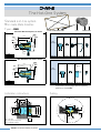
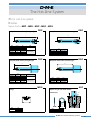
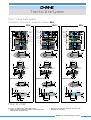
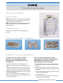
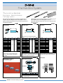
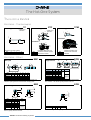
Tips for Gate Mate 4TM nozzles - GMT
Hard wear
H
H
3x
3x
4x
Ø
Ø
Ø
REF.
H
Ø
REF.
H
Ø
REF.
H
Ø
GMT 2
44
0,61
GMT 0300
44
0,61
GMT 0301
44
0,25
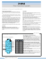
Used with general purpose materials.
Standard tip is made of copper alloy.
Used with abrasive materials.
Hard wear tip is made of carbide.
Used with small gates.
Super sharp tip is made of copper alloy.
No hole
How to order
H
H
Thru hole
Ø
Ø
Ø 1,27
REF.
H
Ø
REF.
H
Ø
GMT 0302
43
2,29
GMT 0303
44
0,61
Used to eliminate potential flow lines.
Thru hole tip is made of copper alloy.
Used to align the flow lines.
No hole tip is made of copper alloy.
D-M-E Runnerless Molding Systems
36
Super sharp
H
Standard
To order a complete Gate Mate 4TM
GMB nozzle:
1. Select one of the available SubAssembly reference numbers.
2. Select the reference number of
the corresponding tip.
3. Both reference numbers as
listed under 1. and 2. are
required to get the right delivery.
The Hot-One System
Standard Hot-One system
Ø 40
Manifold line
Min 6
Ø 38
H6
Max 20
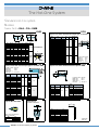
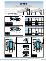
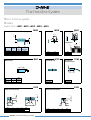
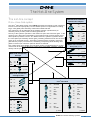
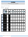
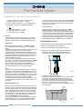
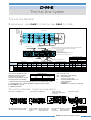
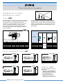
Installation Instructions - Gate Mate 4TM nozzle - GMB
Gating
90°
R3
80°
20
Z
R5 spherical radius
Max 4.5
Min 1
16
To suit
Wiring channel
Fitting instructions
1. Machine the nozzle's seat directly into the mold for
best results.
2. For best gate appearance (lowest gate vestige),
design tip to be ,0 to 0,13 mm back from the cavity
at room temperature. Maintain a minimum
clearance of 0,25 mm around the tip through the
gate in the "hot" position. To achieve best material
flow, position tip up to 0,5 mm maximum back from
cavity. This position will result in a higher gate
vestige.
3. Provide maximum water cooling in cavity insert
around gate.
4. Machine seat area following dimensions carefully.
Hold the 19H6 diameter, as this is a seal-off
dimension.
5. Ensure minimal thermal contact between nozzle
and mold, especially under nozzle shoulder.
6. Route wires through wire channel in retainer plate.
7. Provide a gate dimple on core/cavity opposite gate,
this will allow for best material flow.
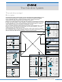
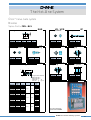
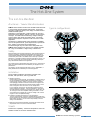
Gate shell insulator - GSI
It fills the space near the gate in Gate Mate 4TM type
applications. This avoids stagnation of the injected
plastic material near the gate, and makes color
changes easier. The material used is virgin Polyimide,
selected for its unique mechanical, thermal and chemical
resistance. Its stability in long periods of time and its
low thermal conductivity make it an ideal choice.
Moreover, the slightly elastic behaviour of virgin Polyimide ensures a perfect sealing of the gate shell space.
The Gate shell insulator is particularly suitable when
injecting plastic materials that degrade easily, either
short or long term. In many cases, the frozen layer of
the processed resin will be eliminated completely so
that no stagnation will occur.
0.8
30°
R9,5
0.15
R3
land (max)
F* = A +
A
H6
F* in operating temperature
Ø 19
25.4
3.5
Ø 32
Z
REF.
GMB 0150 EX
GMB 0151 EX
GMB 0152 EX
GMB 0153 EX
GMB 0154 EX
GMB 0155 EX
GMB 0156 EX
A
50,8
63,5
76,2
88,9
101,6
127,0
152,4
A1
49,8
62,5
75,2
87,9
100,6
126,0
151,4
Dim. A1 refers to the thru hole tip.
IMPORTANT: Use also "A" value for the installation of thru hole tips.
Note:
The expansion factor must be taken into consideration
prior to machining for, and installing nozzle.
∆A = A x αc x 10-6 x ∆T
αc = 16,8 - 0,026 x A
∆T = nozzle set point - 20°C
Example:
Given a 127 mm A dimension, with a nozzle setpoint
temperature of 260 °C.
∆ A = 127 x (16,8 - 0,026 x 127) x 10-6 x (260 - 20 °C) = 0,41 mm
~ 127,41 mm
Thus F* = 127 + 0,41 =
Please note that the above information is given as an
example and not valid for GMT 0300. Use half the value
for carbide tips. Variations may occur based on mold
configurations and cooling factor. In some instances, it
may be necessary to obtain an empirical factor.
REF.
GSI 0001
Installation
Ø 19
D-M-E Runnerless Molding Systems
37
The Hot-One System
Standard Hot-One system
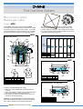
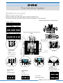
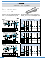
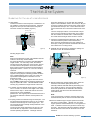
Mini Gate Mate Nozzles
Types - GMB
Mini Gate Mate with Square coil heater
SCH TCG GMB EHR
50.8
GMB EHR
ASSEMBLY consisting of :
GMB
SCH
CIH
Body
EHR
Seal ring Square coil TC type 'J'
heater
Tip
34.9(A)
GMT
Ø 38,1
Ø 15,87
REF.
Assembly
TCG
REF.
GMB 0108
GMB 0108
◆
EHR 0155
SCH 0004
TCG 0100
GMT 0100
Mini Gate Mate with Cast-in heater
ASSEMBLY consisting of :
GMB
50.8
CIH
Body
Seal ring
Cast-in heater
with
TC type 'J'
Tip
◆
EHR 0155
CIH 0100
GMT 0100
EHR
34.9(A)
REF.
Assembly
Ø 38,1
Ø 15,87
GMT
REF.
GMB 0100
GMB 0100
Remark: Tip is not recommended for abrasive materials.
For applications involving highly abrasive engineering
grade resins, contact D-M-E.
Installation Instructions
Gating
(*) F
10.2
1
30°
H6
R3
.2
30°
(*)F = A + ∆A
∆A = A x (11,4 x 10⁻⁶) x ∆T
∆T = T max °C - 20 °C
14
D-M-E Runnerless Molding Systems
38
0,1 max cyl.
2
30°
Ø 0,8 min
90°
10.2
H7
±0,2
Ø 40
Ø 35
Ø 38,1
±0,2
Ø 15,87
Ø 28,5
±0,2
H6
Ø 15,87
The Hot-One System
Standard Hot-One system
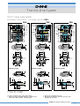
Nozzles
Spare Parts - EHA - CIA - GMB
To be ordered separately
Spare parts for nozzles
Quick
Selection
Chart
Seal
ring
Square
coil
heater
+ TC
type 'J'
Cast-in
Square Thermoheater +
coil
couple
TC type 'J' heater
without
TC
Tip
Sprue gate Extended
EHT
sprue gate
EHT
Standard
GMT
Ring gate
EHT
Point gate
EHT
Hard wear Super sharp Thru hole
GMT
GMT
GMT
No hole
GMT
Hot-One
Nozzles
Conventional
nozzles
Series 250
Conventional
nozzles
Series 375
Conventional
nozzles
Series 625
REF.
REF.
REF.
EHA
EHR
SCH
EHA 0001 EX EHR 0154 SCH 0081
EHA 0002 EX
SCH 0082
EHA 0003 EX
SCH 0083
EHA 0004 EX
SCH 0084
EHA 0005 EX
SCH 0085
EHA 0006 EX
SCH 0086
EHA 0007 EX
SCH 0087
EHA 0008 EX EHR 0155 SCH 0088
EHA 0009 EX
SCH 0089
EHA 0010 EX
SCH 0090
EHA 0011 EX
SCH 0091
EHA 0012 EX
SCH 0092
EHA 0013 EX
SCH 0093
EHA 0014 EX
SCH 0094
EHA 0015 EX
SCH 0095
EHA 0016 EX EHR 0156 SCH 0096
EHA 0017 EX
SCH 0097
EHA 0018 EX
SCH 0098
EHA 0019 EX
SCH 0099
EHA 0020 EX
SCH 0100
EHA 0021 EX
SCH 0101
EHA 0022 EX
SCH 0102
CIA
High
performance
nozzles
Series 250
High
performance
nozzles
Series 375
EHR
SCH
CIA 0001 EX EHR 0154
CIA 0002 EX
CIA 0003 EX
CIA 0004 EX
CIA 0005 EX
CIA 0006 EX
CIA 0007 EX
CIA 0008 EX EHR 0155
CIA 0009 EX
CIA 0010 EX
CIA 0011 EX
CIA 0012 EX
CIA 0013 EX
CIA 0014 EX
CIA 0015 EX
GMB
EHR
GMB 0150 EX EHR 0155
GMB 0151 EX
GMB 0152 EX
Gate Mate 4TM GMB 0153 EX
GMB 0154 EX
GMB 0155 EX
GMB 0156 EX
GMB
EHR
GMB 0108 EHR 0155
Mini Gate Mate
GMB 0100
REF.
CIH
REF.
SCH
REF.
TCG
REF.
GMT
SCH
REF.
EHT
EHT 0005 EX
EHT 0041 EX
EHT 0016 EX EHT 0019 EX EHT 1006 EX
EHT 0017 EX EHT 0020 EX EHT 1007 EX
EHT 0018 EX EHT 0021 EX EHT 1008 EX
EHT 1009 EX
EHT 1037 EX
EHT 1038 EX
EHT 0039 EX
EHT 0042 EX
REF.
GMT
EHT 0022 EX EHT 0023 EX EHT 1040 EX
CIH
SCH
TCG
GMT
CIH 0081 EX
CIH 0082 EX
CIH 0083 EX
CIH 0084 EX
CIH 0085 EX
CIH 0086 EX
CIH 0087 EX
CIH 0088 EX
CIH 0089 EX
CIH 0090 EX
CIH 0091 EX
CIH 0092 EX
CIH 0093 EX
CIH 0094 EX
CIH 0095 EX
SCH
REF.
REF.
REF.
EHT
EHT
EHT
EHT 0010 EX EHT 0013 EX EHT 1001 EX
EHT 0011 EX EHT 0014 EX EHT 1002 EX
EHT 0012 EX EHT 0015 EX EHT 1003 EX
EHT 1004 EX
CIH
CIH
SCH
SCH 0060
SCH 0061
SCH 0062
SCH 0063
SCH 0064
SCH 0065
SCH 0066
SCH
SCH 0004
TCG
GMT
TCG 0060
TCG 0061
TCG 0062
TCG 0063
TCG 0064
TCG 0065
TCG 0066
TCG
GMT
TCG 0100 GMT 0100
Sprue gate
EHT
EHT 0010 EX
EHT 0011 EX
EHT 0012 EX
Ext. sprue gate Ring gate
EHT
EHT
EHT 0013 EX EHT 1001 EX
EHT 0014 EX EHT 1002 EX
EHT 0015 EX EHT 1003 EX
EHT 1004 EX
Point gate
EHT
EHT 0005 EX
EHT 0041 EX
EHT 0016 EX EHT 0019 EX EHT 1006 EX
EHT 0017 EX EHT 0020 EX EHT 1007 EX
EHT 0018 EX EHT 0021 EX EHT 1008 EX
EHT 1009 EX
EHT 1037 EX
EHT 1038 EX
EHT 0039 EX
EHT 0042 EX
Standard
GMT
GMT 2
Hard wear
GMT
GMT 0300
Super sharp
GMT
GMT 0301
Thru hole
GMT
GMT 0302
No hole
GMT
GMT 0303
CIH 0100
D-M-E Runnerless Molding Systems
39
The Hot-One System
Standard Hot-One system
Nozzles
ID
11,10
14,27
23,80
17,45
19,05
6,70
9,56
11,10
14,27
23,80
17,45
19,05
21,00
26,97
Do
14,25
17,42
26,97
20,62
22,22
9,50
12,70
14,25
17,42
26,97
20,62
22,22
24,14
30,18
D
DL max.
Mat.
14,35 11,10
17,55 12,70
27,08 23,80 Aluminium
20,80 16,00
22,37 17,50
9,55
5,20
12,75
8,00
14,35
9,50
17,55 12,70
27,08 23,80 Stainless
20,80 16,00
Steel
22,37 17,50
24,20 18,00
30,25 25,40
Installation
ØD
Ø DL
45° à 60°
Dc < DL
REF.
For
SCH 0081
SCH 0082
SCH 0083
SCH 0084
SCH 0085
SCH 0086
SCH 0087
SCH 0088
SCH 0089
SCH 0090
SCH 0091
SCH 0092
SCH 0093
SCH 0094
SCH 0095
SCH 0096
SCH 0097
SCH 0098
SCH 0099
SCH 0100
SCH 0101
SCH 0102
EHA 0001 EX
EHA 0002 EX
EHA 0003 EX
EHA 0004 EX
EHA 0005 EX
EHA 0006 EX
EHA 0007 EX
EHA 0008 EX
EHA 0009 EX
EHA 0010 EX
EHA 0011 EX
EHA 0012 EX
EHA 0013 EX
EHA 0014 EX
EHA 0015 EX
EHA 0016 EX
EHA 0017 EX
EHA 0018 EX
EHA 0019 EX
EHA 0020 EX
EHA 0021 EX
EHA 0022 EX
Watt Series
L
ID
D
230V
51,00
275
63,50
320
76,00
370
89,00 15,37 21,00 390 250
101,50
460
127,00
460
152,50
500
54,00
370
66,50
415
79,50
500
92,00
640
21,72 27,00
375
105,00
735
130,00
825
156,50
920
181,00
1000
101,50
920
127,00
950
152,50
1000
178,00 37,47 43,00 1000 625
203,00
1100
228,50
1100
254,00
1100
L
D
Aluminium
Stainless Steel
REF. Dc nom.
EHR 0154 6,30
EHR 0155 9,50
EHR 0156 22,20
EHR 0160 12,70
EHR 0162 16,00
EHR 1145 4,00
EHR 1150 5,25
EHR 1154 8,00
EHR 1155 9,50
EHR 1156 18,00
EHR 1160 12,70
EHR 1162 16,00
EHR 1165 17,50
EHR 1168 22,20
SCH
Square coil heater with thermocouple type 'J' for EHA
T
Ø ID
EHR
I.D.
Ø Do
T
Ø ID
1.57
Ø Do
1,3
Seal ring
1.57
Spare Parts - EHA - CIA - GMB
Length of wires: 850 mm
Black wire
230 V
Black wire
230 V
White wire + TC
type 'J'
Red wire -
}
SCH
CIH
Cast-in heater with thermocouple type 'J' for CIA & GMB
L
CIH 0081
CIH 0082
CIH 0083
CIH 0084
CIH 0085
CIH 0086
CIH 0087
CIH 0088
CIH 0089
CIH 0090
CIH 0091
CIH 0092
CIH 0093
CIH 0094
CIH 0095
CIH 0100
CIA 0001 EX
CIA 0002 EX
CIA 0003 EX
CIA 0004 EX
CIA 0005 EX
CIA 0006 EX
CIA 0007 EX
CIA 0008 EX
CIA 0009 EX
CIA 0010 EX
CIA 0011 EX
CIA 0012 EX
CIA 0013 EX
CIA 0014 EX
CIA 0015 EX
GMB 0100
52,37
65,07
77,77
90,47
103,17
128,57
153,97
55,42
68,12
80,82
93,52
106,20
131,62
157,02
182,42
30,00
ID
D
15,85 26,97
22,20 33,32
19,05 27,00
Watt
Series
230V
275
320
370
390
250
460
460
500
370
415
500
640
375
735
825
920
1000
230 Mini Gate Mate
REF.
CIH 9000
D-M-E Runnerless Molding Systems
40
}
Removal tool
for Cast-in heaters
Tip is not recommended for
abrasive materials
For
GMB 0108
GMB 0100
Length of wires
Black wire
Black wire
White wire +
Red wire REF.
L
SCH 0060
SCH 0061
SCH 0062
SCH 0063
SCH 0064
SCH 0065
SCH 0066
SCH 0004
36,50
49,00
62,00
74,50
87,50
113,00
138,00
30,00
D
ID
25,90
19,05
24,00
18,54
Watt
230V
230
275
320
370
390
460
460
230
CIH
GMT
Tip for Mini Gate Mate
I.D.
For
REF.
ØD
Ø ID
TC type 'J'
REF.
GMT 0100
L
D
}
Square coil heater without thermocouple for GMB
L
850 mm
230 V
230 V
47.5
Length of wires
Black wire
Black wire
White wire +
Red wire -
850 mm
230 V
230 V
TC type 'J'
For
GMB 0150 EX
GMB 0151 EX
GMB 0152 EX
GMB 0153 EX
GMB 0154 EX
GMB 0155 EX
GMB 0156 EX
Mini Gate Mate
TCG
Thermocouple
L
REF.
TCG 0060
TCG 0061
TCG 0062
TCG 0063
TCG 0064
TCG 0065
TCG 0066
TCG 0100
L
25,00
37,50
50,00
63,00
75,50
101,00
136,50
25,20
For
GMB 0150 EX
GMB 0151 EX
GMB 0152 EX
GMB 0153 EX
GMB 0154 EX
GMB 0155 EX
GMB 0156 EX
GMB 0108
White wire +
Red wire -
The Hot-One System
The Hot-One concept
Micro system
Manifold Ancillaries
Heated nozzle adapters
➛
EHN
➛
EHL
➛
➛
The benefit of the Micro Hot-One system can be subscribed to the implementation of a new
and revolutionary generation of heating elements, developed and patented by D-M-E.
These insulated and cast-in heating elements feature a special multi-layer
construction and reduce heat loss to the mold by up to 60 %.
Because of the flat temperature profile and fast reaction to temperature fluctuations,
the Micro Hot-One system is most suitable for materials that are difficult to process.
A nozzle diameter of 17 mm and minimal heat loss to the mold allow for center-tocenter distances below 20 mm without accumulation of heat.
The air insulation between heating element and mold can be limited to 0.3 - 0.5 mm.
Because of the small dimension and geometry of the orifice diameter, color and
material change are realized very quickly.
Shot weights between 0.5 g and 12.0 g in single or multi-cavity molds are possible.
The consequent usage of special titanium alloys for all system components in contact
with the mold helps with the heat regulation of this Hot-One system.
p. 66
HR
DR
➛
➛
➛
Manifold Ancillaries
p. 67
End caps
Manifold Ancillaries
EHM ➛
Riser pads
➛
p. 72
p. 71
Spacer rings (no view)
EHM ➛
➛
p. 71
Support blocks (no view)
TCM
EHR
ECB
WTO
MGS
BHF
➛
MEP
➛
CHR ➛
ECB
p. 72
➛
Cartridge heaters
➛
➛
➛
➛
Manifold Ancillaries
MEO
Nozzles & Accessories
➛
MHD ➛
Tubular➛
p. 68/70
Thermocouples (no view)
ETC ➛
MDS ➛
p. 42
MSO
MEO
DEO ➛
ETC ➛
MHD
MDS
p. 43
➛
➛
DEP
MSR
DSP
➛
ECH ➛
EHP ➛
MSP
➛
MEP
➛
➛
CHS ➛
MGS
MSR
DSO
MHD ➛
p.71/72
p. 42
MHD
➛
MDS ➛
➛
ETC ➛
TCM ➛
ESR
p. 72
➛
EEP ➛
ERP
➛
GZ ➛
EEP ➛
EDR
➛
DI
WTO
BHA
MDS
p. 43
p. 44/45
D-M-E Runnerless Molding Systems
41
The Hot-One System
Micro Hot-One system
Screw head nozzles
Types - Point gate - MEP
- Thru hole - MEO
MDS
MHD
DEP MDS
MEP
L
M
6
Body
Flange
Cast-in
heater + TC
type 'J'
REF.
Assembly
Ø 16
Ø 17
DEO
ASSEMBLY consisting of :
M 12 x 1
Point gate type
MHD
Mat.
7
REF.
MEP 0060
MEP 0070
MEP 0080
REF.
MEP 1060
MEP 1070
MEP 1080
L+0,02
66
76
86
MHD
M
59
69
79
Thru hole type
MEP 0060
MEP 0070
MEP 0080
MEP 1060
MEP 1070
MEP 1080
DEP
MEO
L1
M1
MDS 0001
Ø 17
MDS
Standard
Wear
resistant
ASSEMBLY consisting of :
Body
Flange
DEO 0060
DEO 0070
DEO 0080
MDS 0001
Cast-in
heater + TC
type 'J'
Mat.
REF.
Assembly
7
L1+0,02
65
75
85
MHD 0044
MHD 0054
MHD 0064
MHD 0044
MHD 0054
MHD 0064
MDS 0001
Ø 16
6
REF.
MEO 0060
MEO 0070
MEO 0080
DEP 0060
DEP 0070
DEP 0080
DEP 1060
DEP 1070
DEP 1080
M 12 x 1
MDS
MHD
M1
58
68
78
DEO
MEO 0060
MEO 0070
MEO 0080
MHD 0044
MHD 0054
MHD 0064
Standard
Installation Instructions
Point gate type
Screw head details
Thru hole type
M 12 x 1
M 12 x 1
Ø 3,5
Ø 3,5
0,15
L-6
L
34°
L
L-6
H7
45°
Ø 17,25
14 min
Ø 17
8min
Point gate
6 ± 0,05
Ø 17,25
+0.05
Gating
10
14 min
8min
1
6
6
M 12 x 1
Ø 17,25
Ø 0,6 min
L
66
76
86
D-M-E Runnerless Molding Systems
42
Ø 17
H7
34°
Ø 17 H7
0,15
REF.
MEP 1060
MEP 1070
MEP 1080
Thru hole
45°
30°
REF.
MEP 0060
MEP 0070
MEP 0080
H7
6 ± 0,05
Ø 17
10 +0.05
Ø 17,25
Ø 0,8 min
Ø 3,4
Ø 2,0 max
REF.
MEO 0060
MEO 0070
MEO 0080
L
66
76
86
The Hot-One System
Micro Hot-One system
Flat head nozzles
Types - Point gate - MSP
- Thru hole - MSO MDS
MHD
DSP
MSR MDS
MSP
Point gate type
A
Seal ring
Mat.
MSP 0060
MSP 0070
MSP 0080
MSP 1060
MSP 1070
MSP 1080
MSR
DSP 0060
DSP 0070
DSP 0080
DSP 1060
DSP 1070
DSP 1080
MDS 0001
MDS 0001
MHD 0044
MHD 0054
MHD 0064
MHD 0044
MHD 0054
MHD 0064
MSR 6408 Standard
MSR 6408
Wear
resistant
Seal ring
Mat.
ASSEMBLY consisting of :
Flange
Cast-in
heater + TC
type 'J'
DSO 0060
DSO 0070
DSO 0080
MDS 0001
REF.
Assembly
MHD
DSO
A1+0,03
-0,01
46,5
56,5
66,5
Body
Ø 22
Ø 21
22
Ø 16
Ø 17
Cast-in
heater + TC
type 'J'
REF.
Assembly
MSO
A1
MDS
REF.
MSO 0060
MSO 0070
MSO 0080
Ø 21
DSP
Thru hole type
Flange
MHD
A+0,03
-0,01
47,5
57,5
67,5
REF.
MSP 1060
MSP 1070
MSP 1080
Ø 22
Ø 16
Ø 17
REF.
MSP 0060
MSP 0070
MSP 0080
DSO MSR
ASSEMBLY consisting of :
22
Body
MDS
MHD
MSR
MSO 0060
MSO 0070
MSO 0080
MHD 0044
MHD 0054
MHD 0064
MSR 6408 Standard
Installation Instructions
Thru hole type
Flat head details
Gating
3.5 min
Ø 17,25
H7
Ø 17,25
0,15
45°
34°
A
Ø 17
6 ± 0,05
10
+0.05
Point gate
A
Ø 17,25
Ø 22 H7
2
22
H7
3.5 max
3.5 min
Ø 22
2
22
Point gate type
Ø 0,6 min
A
47,5
57,5
67,5
Ø 17
34°
6 ± 0,05
H7
Ø 17
0,15
REF.
MSP 1060
MSP 1070
MSP 1080
Thru hole
H7
45°
30°
REF.
MSP 0060
MSP 0070
MSP 0080
H7
10 +0.05
Ø 17,25
Ø 17
Ø 0,8 min
Ø 3,4
Ø 2,0 max
REF.
MSO 0060
MSO 0070
MSO 0080
A
47,5
57,5
67,5
D-M-E Runnerless Molding Systems
43
The Hot-One System
Micro Hot-One system
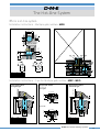
Multiple gate nozzles
Types - MGS
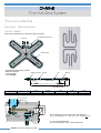
The Multiple gate nozzle developed by D-M-E
increases the potential number of cavities for a mold
by allowing up to six cavities per nozzle. It provides
precise temperature control resulting in an excellent
temperature balance between the individual gates.
MGS
Multiple gate nozzles
D/3
WTO
Seal
ring
Band TC
heater Type 'J'
10
Ø 36
Ø 25
6
Body Support Support Insulablocks blocks ting
ring
TCM
REF.
SubAssembly
45
BHF
MGS 3802
MGS 3804
MGS 6003
MGS 6006
6
ECB
L1
L
10 *
C
MEO
◆
◆
◆
◆
ECB 0501
BHF 3870
ECB 0500 WTO 3000 EHR 1150
ECB 0502
TCM 0003
BHF 3890
Tips for Multiple gate nozzles
MEP
MEP
Screw head nozzle - point gate type
B
L
A
M
4 tips
6
6 tips
M 12 x 1
51
SUB-ASSEMBLY consisting of :
EHR
Ø 16
ECB
The Multiple gate nozzle fits into a small mold base,
cutting equipment cost and reducing the size of the
injection machine required. The nozzle tips are made
of a wear resistant material that provides high thermal
conductivity and long service life.
Ø 16
Ø 17
60
°
90
°
60°
7
MDS
A
70
70
90
90
B
38
38
60
60
REF. Assembly
MEP 0060 MEP 1060
MEP 0070 MEP 1070
MEP 0080 MEP 1080
Ø 60
C
20
20
40
40
D
54/3
54/3
72/3
72/3
* min. 6 mm
How to order
L+0,02
66
76
86
M
59
69
79
DEP
MEO
Screw head nozzle - thru hole type
L1
M1
Remarks: For single application, use the insulating ring
WTO 3000. Radius to be made by customer. For applications under a manifold, use the seal ring EHR 1150.
D-M-E Runnerless Molding Systems
44
Ø 17
Ø 16
6
To order a complete Multiple gate nozzle:
1. Select one of the available Sub-Assembly reference
numbers.
2. Select the reference number of the corresponding Point
gate or Thru hole tip of the Screw head type.
3. Both reference numbers as listed under 1. and 2. are
required to get the right delivery.
7
MDS
REF. Assembly
MEO 0060
MEO 0070
MEO 0080
L1+0,02
65
75
85
M1
58
68
78
MHD
DEO
M 12 x 1
Ø 38
REF.
MGS 3802
MGS 3804
MGS 6003
MGS 6006
MHD
The Hot-One System
Micro Hot-One system
Installation Instructions - Multiple gate nozzles - MGS
ØC
20 min
50
ØP
L+45
51
L -16 min
30 min
8,5
L-6
DR
HR
DI
WTO BHA
60°
ERP
EEP
90°
60°
Ø 38
Ø 60
MGS
P
70
90
C
105
125
H
L + 45
L + 45
ECB
ESR
ECB
Installation Instructions - Tips for Multiple gate nozzles - MEP - MEO
Screw head nozzles
Point gate type
Screw head nozzles
Screw head nozzles
Thru hole type
Gating
10 nom. (6 min.)
10 nom. (6 min.)
Point gate
34°
14 min
0,15
14 min
10
Ø 17 H7
45°
6 ± 0,05
+0.05
Ø 17,25 Min.
L-6
Ø 17,25
L-6
L
L
Ø 0,6 min
Thru hole
Ø 17,25
REF.
MEP 0060
MEP 0070
MEP 0080
REF.
MEP 1060
MEP 1070
MEP 1080
L
66
76
86
34°
6 ± 0,05
H7
0,15
Ø 17
Ø 17 H7
45°
30°
10 +0.05
Ø 17,25 Min.
Ø 0,8 min
Ø 3,4
Ø 2,0 max
Ø 17 H7
REF.
MEO 0060
MEO 0070
MEO 0080
L
66
76
86
D-M-E Runnerless Molding Systems
45
The Hot-One System
Micro Hot-One system
Nozzles
Spare Parts - MEP - MEO - MSP - MSO - MGS
To be ordered
separately
Spare parts for nozzles
Body
DEP
DEO
Cast-in heater
TC type 'J'
Flange
Seal ring
Material
Spacer ring
REF.
MHD
MHD 0044
MHD 0054
MHD 0064
MHD 0044
MHD 0054
MHD 0064
MHD
MHD 0044
MHD 0054
MHD 0064
MHD
MHD 0044
MHD 0054
MHD 0064
MHD 0044
MHD 0054
MHD 0064
MHD
MHD 0044
MHD 0054
MHD 0064
REF.
MDS
REF.
MSR
REF.
Mat.
REF.
ASF
Quick
Selection
Chart
DSP
DSO
Micro
Hot-One
Nozzles
REF.
Screw head
nozzles
Point gate type
Screw head
nozzles
Thru hole type
Flat head
nozzles
Point gate type
Flat head
nozzles
Thru hole type
REF.
MEP
MEP 0060
MEP 0070
MEP 0080
MEP 1060
MEP 1070
MEP 1080
MEO
MEO 0060
MEO 0070
MEO 0080
MSP
MSP 0060
MSP 0070
MSP 0080
MSP 1060
MSP 1070
MSP 1080
MSO
MSO 0060
MSO 0070
MSO 0080
REF.
DEP
DEP 0060
DEP 0070
DEP 0080
DEP 1060
DEP 1070
DEP 1080
DEO
DEO 0060
DEO 0070
DEO 0080
DSP
DSP 0060
DSP 0070
DSP 0080
DSP 1060
DSP 1070
DSP 1080
DSO
DSO 0060
DSO 0070
DSO 0080
MDS 0001
Standard
MDS 0001
Wear
resistant
MDS
MSR
MDS 0001
Mat.
Standard
MDS
MSR
Mat.
ASF
MDS 0001
MSR 6408
Standard
ASF 0218
MDS 0001
MSR 6408
Wear
resistant
ASF 0218
MDS
MSR
Mat.
ASF
MDS 0001
MSR 6408
Standard
ASF 0218
To be ordered
separately
Spare parts for nozzles
Body
Insulating
ring
ASF
Support
Support
Band heater
block (lower) block (upper)
Thermocouple
Type 'J'
Seal ring
Nozzle
Assembly
MEP
Multiple
gate nozzles
REF.
MGS
MGS 3802
MGS 3804
MGS 6003
MGS 6006
REF.
◆
◆
◆
◆
REF.
WTO
WTO 3000
D-M-E Runnerless Molding Systems
46
REF.
ECB
ECB 0501
ECB 0501
ECB 0502
ECB 0502
REF.
ECB
ECB 0500
REF.
BHF
BHF 3870
BHF 3870
BHF 3890
BHF 3890
REF.
TCM
REF.
EHR
TCM 0003
EHR 1150
MEO
REF.
MEP
MEP 0060
MEP 0070
MEP 0080
MEP 1060
MEP 1070
MEP 1080
MEO
MEO 0060
MEO 0070
MEO 0080
The Hot-One System
Micro Hot-One system
Nozzles
Spare Parts - MEP - MEO - MSP - MSO - MGS
Body-Screw head nozzle, point gate type
DEP
Body-Screw head nozzle, thru hole type
L
REF.
DEP 0060
DEP 0070
DEP 0080
DEP 1060
DEP 1070
DEP 1080
L+0,02
66
76
86
66
76
86
For
MEP 0060
MEP 0070
MEP 0080
MEP 1060
MEP 1070
MEP 1080
L1
Mat.
Standard
REF.
DEO 0060
DEO 0070
DEO 0080
Wear resistant
Body-Flat head nozzle, point gate type
DSP
L1+0,02
65
75
85
For
MEO 0060
MEO 0070
MEO 0080
Body-Flat head nozzle, thru hole type
A
REF.
DSP 0060
DSP 0070
DSP 0080
DSP 1060
DSP 1070
DSP 1080
A+0,03
-0,01
47,5
57,5
67,5
47,5
57,5
67,5
For
MSP 0060
MSP 0070
MSP 0080
MSP 1060
MSP 1070
MSP 1080
DEO
DSO
A1
Mat.
Standard
REF.
DSO 0060
DSO 0070
DSO 0080
Wear resistant
MDS
Flange
A1+0,03
-0,01
46,5
56,5
66,5
For
MSO 0060
MSO 0070
MSO 0080
Spacer ring for Flat head nozzles
3 min.
Installation
ASF
ASF
Ø 17
2
Ø 17.25
Ø 21.8
REF.
MDS 0001
For
MSP - MSO
MEP - MEO
REF.
ASF 0218
For
MSP - MSO
D-M-E Runnerless Molding Systems
47
The Hot-One System
Micro Hot-One system
Nozzles
Spare Parts - MEP - MEO - MSP - MSO - MGS
Cast-in heater with thermocouple type 'J'
MHD
MSR
Seal ring
EHR
Seal ring
Ø 12,7
Ø 9,56
Ø 16
Ø 6,4
Ø 4,8
Ø 12,7
1,3
Ø8
Installation
REF.
Watt
230 V
MHD 0044
MHD 0054
MHD 0064
175
190
200
For
MSP
MEP
1060
1070
1080
Ø8
For
MSP - MSO
MEP - MEO
0060
0070
0080
REF.
MSR 6408
BHF
REF.
EHR 1150
WTO
TCM
Insulating ring
Cylindrical
Thermocouple
3
Band heater
For
MSP - MSO
A
10
REF.
ØA
BHF 3870
BHF 3890
70
90
Watt
230 V
780
1100
REF.
WTO 3000
ECB
ECB
Support block (upper)
X
X
X
Support block (lower)
REF.
TCM 0003
Ø d1
Ød
REF.
ECB 0501
ECB 0502
Ød
Ød
X
10
10
d
20
40
d1
5,2
8,2
Mat.
Titanium
D-M-E Runnerless Molding Systems
48
Ø d1
Ø d1
REF.
ECB 0500
X
6
d
16
d1
4,2
Mat.
Titanium
The Hot-One System
Standard Hot-One system
Machining Instructions
Manifold, Nozzle plate, Mold plate gate machining dimensions for:
Conventional and High performance Hot-One nozzles, Gate Mate 4TM, Mini Gate Mate.
Machining dimensions for heated adapter
Locating rings EHL
Heated adapters
L ±1
EHL
ØN
30
41
54
32
28,5
Ø7
1
F
G
45°
H
J
Riser pad height
min 6.0
16 min
Cooling lines
Height = riser pads
spacer ring and manifold
6
Ø 19
M8
Extended sprue gate
∆A = A x (11,4 x 10⁻⁶) x ∆T
(∆T = T max . °C - 20 °C)
A
Recommended
3,0
3,0 min
36
16
30°
R9,5
20
6,35 min
N
A+ ˘A
Conventional and
High performance
nozzle
R3
F* = A +
25,4
M
Height of spacer ring
and center support block
min 6,0
in
4m
Manifold height
K
Gate Mate 4TM
Cooling lines
90°
Ø 15,87
R 3.2
A
30°
30°
Sprue and Ring gate
∆A = A x (11,4 x 10⁻⁶) x ∆T
(∆T = T max . °C - 20 °C)
REF.
250
375
625
N
30
40
54
L
2
2
4
T
12,5
19
25
2
Ø 0,8 min
10.2
0,15
~0.5
Conventional and
High performance
nozzle
T H6
2.5
d
R
T
4.5
30°
H6
80°
30°
0,1 max cyl.
A+
L
A+
A
N
H6
90°
Min 1
Max 4.5
Gate Mate 4TM
∆A = A x αc x 10-6 x ∆T
(αc = 16,8 - 0,026 x A)
(∆T = nozzle set point - 20°C)
(not valid for GMT 0300)
Conventional and
High performance
nozzle
Point gate
∆A = A x (11,4 x 10⁻⁶) x ∆T
(∆T = T max . °C - 20 °C)
REF.
Ød
ØT
R
250 1,5-3,0 9,5 3,2
375 2,0-4,0 12,5 4,7
R5
0.8
ØM
38
50
76
38
38,1
8,5 (2 pieces)
K
40
52
78
40
40
M
A
Machining dimensions for locating ring
Nozzles
REF.
250
375
625
Gate Mate 4TM
Mini Gate Mate
B
M8 x 4
+0,5
A±0,02
ØB±0,2
ØC±0,5
L±1min
BHA-M24
24 x 1,5
18
27
60
80
H7
2,5 -0
BHA-M20
20 x 1,5
14,8
24
50
75
M
Ø 90
C
25
ØJ
64
95
10
ØH
75
100
32
ØG
84,1
118
0.15
ØF
101,5
139,7
Min 5 +0,1
REF.
EHL 0252 EX
EHL 0253 EX
Mini Gate Mate
∆A = A x (11,4 x 10⁻⁶) x ∆t
(∆T = T max °C - 20°C)
REF.
GMB 0150 EX
GMB 0151 EX
GMB 0152 EX
GMB 0153 EX
GMB 0154 EX
GMB 0155 EX
GMB 0156 EX
A
50,8
63,5
76,2
88,9
101,6
127,0
152,4
D-M-E Runnerless Molding Systems
49
The Hot-One System
Micro Hot-One system
Machining Instructions
Manifold, Nozzle plate, Mold plate gate machining dimensions for:
Micro Hot-One nozzles and Multiple gate nozzles.
Micro Hot-One nozzles
Micro Hot-One nozzles
14 min
14 min
{3.5 min}
2
22
Ø 22
H7
Ø 17,25
Ø 17,25
Ø 17,25
A
Ø 17,25
A
L -6
L -6
L
L
H7
Ø 22
2
Ø 3,5
6min
Ø 3,5
6min
M 12 x 1
{3.5 min}
Flat head style
M 12 x 1
22
Screw head style
Ø 17
H7
Ø 17
Gating
Gating
Gating
Thru hole type
Point gate type
Thru hole type
Ø 17,25
REF.
MEP 1060
MEP 1070
MEP 1080
REF.
MEO 0060
MEO 0070
MEO 0080
L
66
76
86
+0.05
34°
6
± 0,05
Ø 17
10
34°
+0.05
± 0,05
10
H7
REF.
MSP 0060
MSP 0070
MSP 0080
Ø 0,6 min
REF.
MSP 1060
MSP 1070
MSP 1080
REF.
MSO 0060
MSO 0070
MSO 0080
Ø 0,8 min
Ø 3,4
Ø 2,0 max
A
47,5
57,5
67,5
Multiple gate nozzles with Screw head nozzles
ØC
ØP
50
60°
20 min
90°
60°
8,5
Ø 38
Ø 60
L -16 min
30 min
51
L-6
L+45
D-M-E Runnerless Molding Systems
P
70
90
C
105
125
H
L + 45
L + 45
H7
0,15
Ø 2,0 max
0,15
0,15
Ø 0,8 min
Ø 3,4
Ø 17
6
34°
6
± 0,05
+0.05
10
0,15
Ø 0,6 min
Ø 17,25
Ø 17,25
H7
45°
34°
Ø 17
45°
6
H7
45°
30°
± 0,05
Ø 17
REF.
MEP 0060
MEP 0070
MEP 0080
50
H7
Gating
45°
30°
+0.05
Ø 17
H7
Ø 17
Point gate type
Ø 17,25
10
H7
The Hot-One System
The Hot-One concept
Manifold Ancillaries
Heated nozzle adapters
EHN
➛
EHL
➛
➛
p. 66
HR
DR
➛
➛
➛
DI
WTO
BHA
p. 67
Manifold Ancillaries
Riser pads (no view)
➛
The Osco® Valve Gate system from D-M-E represents the ultimate in part cosmetics,
knit line control and part quality over the widest spectrum of applications including
large, multi-gated parts and family molds with unbalanced flow.
This superiority can be attributed to the floating hydraulic cylinder/valve pin
assembly which provides positive indivual gate shut-off
The key to the system's operation is the method to open and close each gate. In the
opening cycle, delay timers activated by the machine's high-pressure clamp circuit
allow injection pressure to build. At a determined time, hydraulic cylinders retract
the valve piston/pin assembly at each gate, permitting material to flow into the mold
cavity at an increased velocity. Secondary individual timers positively close each
gate after the proper pre-set fill time, eliminating overpacking while allowing other
gates to remain open until their optimum fill time is reached.
Two nozzle styles are available: the Full-Body nozzle is suggested when a circular
nozzle mark is allowed, the Bodyless nozzle offers impeccable cosmetics, feeding
directly into the part.
➛
Osco Valve Gate system
®
ERP
p. 72
Manifold Ancillaries
Spacer rings
End caps
➛
EHM ➛
ESR
p. 72
Support blocks
➛
GZ ➛
EEP ➛
EDR
➛
p. 73
ECB
p. 72
EHM ➛
EEP ➛
p. 73
Manifold Ancillaries
Cartridge heaters
Nozzles & Accessories
CHR ➛
Osco® Valve Gate
CHS ➛
FBV
➛
VG-HCA
VG-HCA
➛
➛
➛
➛
VG
PBR
PB
EHR
➛
➛
➛
➛
VP
PBR
PB
EHR
➛
FBV
➛
BLV
➛
SCH
➛
SCH
➛
➛
PG
VG-FBT
➛
➛
Thermocouples (no view)
VG-VPR
➛
p. 68/70
➛
Tubular➛
➛
ECH ➛
EHP ➛
BLV
VG-VPR
PG
VG-BLT
ETC ➛
ETC ➛
ETC ➛
TCM ➛
p.71/72
p. 52/53
p. 54/55
D-M-E Runnerless Molding Systems
51
The Hot-One System
OSCO® Valve Gate system
Full-Body nozzles - FBV
VG-FBT
FBV
FBV
L
O
3,17
4,95
9,11
min. 2,03
max.3,81
FBV
16.5
A
Ø7.9
Ø76.2
30°
Hydraulic cylinder
Manifold pin bushing
Full-Body tip
Hydraulic cylinder
38.1
REF.
A
REF.
A
FBV 2040
FBV 2050
FBV 2060
FBV 2070
101,60
127,00
152,40
177,80
FBV 2080
FBV 2090
FBV 2100
203,20
228,60
254,00
T
L
O
12,70
19,05
25,40
3,17
4,75
9,11
min. 3,81
max. 6,35
D-M-E Runnerless Molding Systems
52
Body
Assembly
Square coil heater
Ø45
VG-VPR
REF.
Ø15.9
T
O
VG-FBT PG VP SCH FBV EHR PB PBR VG-HCA
ASSEMBLY consisting of :
Seal ring
Series 200
Hydraulic cylinder
T
12,70
19,05
25,40
Manifold pin bushing
A
101,60
127,00
152,40
177,8
Full-Body tip
REF.
FBV 1040
FBV 1050
FBV 1060
FBV 1070
SCH 0088
SCH 0089
SCH 0090
SCH 0091
EHR 0155
PG 100 VP 100x14 VG 100-VPR VG 100-FBT PBR 100 PB 100 VG 100-HCA
SCH 0092
SCH 0093
SCH 0094
SCH 0095
Valve pin retainer
A
50,80
63,50
76,20
88,90
◆
◆
◆
◆
◆
◆
◆
◆
Valve pin
REF.
FBV 1020
FBV 1025
FBV 1030
FBV 1035
FBV 1020
FBV 1025
FBV 1030
FBV 1035
FBV 1040
FBV 1050
FBV 1060
FBV 1070
Pin guide
28.58
with TC type 'J'
14.5
A
L
Valve pin retainer
Ø4.75
30°
Ø50.8
Ø11
Assembly
Manifold pin bushing
REF.
Square coil heater
Body
VG-VPR
Ø38
T
O
PG SCH VP FBV EHR PB PBR VG-HCA
ASSEMBLY consisting of :
Seal ring
Series 100
Pin bushing retainer
O
min. 1,27
max. 2,03
Pin bushing retainer
L
2,29
3,17
4,95
Full-Body tip
T
9,52
12,70
19,05
Valve pin retainer
A
101,60
127,00
152,40
SCH 0081
SCH 0082
SCH 0083
EHR 0154 SCH 0084 PG 50 VP 50x14 VG 50-VPR VG 50-FBT PBR 50 PB 50 VG 50-HCA
SCH 0085
SCH 0086
SCH 0087
Valve pin
REF.
FBV 540
FBV 550
FBV 560
◆
◆
◆
◆
◆
◆
◆
Pin guide
A
50,80
63,50
76,20
88,90
FBV 520
FBV 525
FBV 530
FBV 535
FBV 540
FBV 550
FBV 560
with TC type 'J'
REF.
L
Valve pin
25.4
FBV 520
FBV 525
FBV 530
FBV 535
VG-FBT
Pin bushing retainer
Ø3.2
Ø38.1
11.0
A
Assembly
Square coil heater
VG-VPR
Seal ring
Ø24.5
VG-HCA
REF.
Ø8
30°
L
PB PBR
Body
T
O
PG SCH VP FBV EHR
Pin guide
ASSEMBLY consisting of :
Series 50
VG-FBT
VP
The unique removable tip construction provides maximum
flexibility. There is no need to replace the whole unit, yet
it has longer life than conventional floating pin units,
which causes misaligned pin/orifice engagement.
with TC type 'J'
The Full-Body Valve Gate nozzle is designed to feed
the part or runner and is ideal for use where the
nozzle circular mark is allowed. It is supplied with a
thermocouple controlled spiral heater that distributes
heat throughout the nozzle uniformly.
FBV
FBV 2040
FBV 2050
FBV 2060
FBV 2070
FBV 2080
FBV 2090
FBV 2100
◆
◆
◆
◆
◆
◆
◆
SCH 0096
SCH 0097
SCH 0098
EHR 0156 SCH 0099 PG 200 VP 200x14 VG 200-VPR VG 200-FBT PBR 200 PB 200 VG 200-HCA
SCH 0100
SCH 0101
SCH 0102
The Hot-One System
Osco® Valve Gate system
Installation Instructions - Full-Body nozzles - FBV
56 nom.
51 min.
66 nom.
57.5 min.
46 min.
56 min.
6 min.
A + 146.6 nom.
28.6
Ø38.1
(A + 141.6 min.)
25.4
+0.04
+0.02
A + 176.1 nom.
6 min.
66min.
(A + 125.4 min.)
A + 133.4 nom.
48 min.
6 min.
FBV
Series 200
38.1
(A + 167.6 min.)
56 nom.
FBV
Series 100
6 min.
FBV
Series 50
+0.05
A
A
A
100
Ø40
16
16
80
16
70
Ø54
+0.04
Ø38.1+0.02
0.5 x 45°
0.5 x 45°
0.5 x 45°
2.0
Ø50
2.0
2.0
Ø42
Hydraulic cylinder
T
T
Hydraulic cylinder
Hydraulic cylinder
125
+0
9.7 -0.05
22.1
+0.02
-0
57.5 min.
30
+0.02
-0.02
12.85
+0.02
-0
51 min.
25.25
0.5x45°max
0.5x45°max
32
+0.02
-0.02
6.5
0.5x45°max
30
125
25
105
+0
-0.02
30°
30°
30°
T
34.8
+0.05
+0.02
3.0
Ø76.2
3.0
3.0
Ø78
+0.05
+0.02
Ø50.8
Ø28.5
48 min.
Ø76.2 +0.02
6 min.
6 min.
+0.05
Ø50.8 +0.02
0.8x45°
Ø46
+0.03
-0.07
+0.05
-0.05
+0.03
Ø92.1 -0.07
Ø98.4
+0.08
-0.02
0.8x45°
Ø104.8
Ø114.3
+0.03
-0.07
25
Ø39.7
25
0.8x45°
+0.05
-0.05
How to order
To order a complete Osco® Valve Gate nozzle:
1. Select one of the available reference numbers of the
Osco® Valve Gate nozzles - Full-Body type.
2. Specify the T-diameter of the tip.
3. Specify the O-diameter, which can be of any size
between min. and max.
D-M-E Runnerless Molding Systems
53
The Hot-One System
OSCO® Valve Gate system
Bodyless nozzles - BLV
VG-BLT
BLV
11.0
BLV
BLV
16.5
A
REF.
BLV 2040
BLV 2050
BLV 2060
BLV 2070
A
101,60
127,00
152,40
177,80
Ø7.9
Ø76.2
Ø15.9
O
38.1
REF.
BLV 2080
BLV 2090
BLV 2100
A
203,20
228,60
254,00
O
min. 3,81
max. 6,35
D-M-E Runnerless Molding Systems
54
BLV 2040
BLV 2050
BLV 2060
BLV 2070
BLV 2080
BLV 2090
BLV 2100
◆
◆
◆
◆
◆
◆
◆
Hydraulic cylinder
Manifold pin bushing
Pin bushing retainer
Bodyless tip
Valve pin retainer
Manifold pin bushing
Pin bushing retainer
Bodyless tip
Valve pin retainer
Hydraulic cylinder
Hydraulic cylinder
Assembly
Square coil heater
REF.
Seal ring
VG-VPR
Ø45
Ø22.2
VG-BLT PG VP SCH BLV EHR PB PBR VG-HCA
ASSEMBLY consisting of :
Body
Series 200
Manifold pin bushing
O
min. 2,03
max.3,81
Pin bushing retainer
A
101,60
127,00
152,40
177,80
SCH 0088
SCH 0089
SCH 0090
SCH 0091
EHR 0155
PG 100 VP 100x14 VG 100-VPR VG 100-BLT PBR 100 PB 100 VG 100-HCA
SCH 0092
SCH 0093
SCH 0094
SCH 0095
Bodyless tip
REF.
BLV 1040
BLV 1050
BLV 1060
BLV 1070
◆
◆
◆
◆
◆
◆
◆
◆
Valve pin retainer
A
50,80
63,50
76,20
88,90
BLV 1020
BLV 1025
BLV 1030
BLV 1035
BLV 1040
BLV 1050
BLV 1060
BLV 1070
28,58
Valve pin
A
REF.
BLV 1020
BLV 1025
BLV 1030
BLV 1035
Ø4.75
14.5
Ø50.8
Ø11
O
Assembly
Square coil heater
REF.
Seal ring
VG-VPR
Ø38
Ø15.9
VG-BLT PG SCH VP BLV EHR PB PBR VG-HCA
ASSEMBLY consisting of :
Body
Series 100
Valve pin
O
min. 1,27
max. 2,03
SCH 0081
SCH 0082
SCH 0083
EHR 0154 SCH 0084 PG 50 VP 50x14 VG 50-VPR VG 50-BLT PBR 50 PB 50 VG 50-HCA
SCH 0085
SCH 0086
SCH 0087
Pin guide
A
101,60
127,00
152,40
◆
◆
◆
◆
◆
◆
◆
Pin guide
REF.
BLV 540
BLV 550
BLV 560
BLV 520
BLV 525
BLV 530
BLV 535
BLV 540
BLV 550
BLV 560
with TC type'J'
A
50,80
63,50
76,20
88,90
25.4
with TC type'J'
A
REF.
BLV 520
BLV 525
BLV 530
BLV 535
Ø3.2
Ø38.1
Ø8
Ø 12.7
O
Assembly
Valve pin
REF.
Square coil heater
VG-VPR
Seal ring
VG-HCA
Body
PB PBR
Ø24.5
PG SCH VP BLV EHR
Pin guide
ASSEMBLY consisting of :
Series 50
VG-BLT
VP
The nozzle is equipped with a pin guide to assure
concentricity within the valve pin and the tapered opening, eliminating the typical wear at the opening. No
need for hardened cavity steel.
with TC type'J'
The Bodyless type nozzle is designed to feed directly into the molded part and to be used where the typical circular mark of the conventional nozzle is not allowed. It is
supplied with a thermocouple controlled spiral heater that
distributes heat throughout the nozzle uniformly.
BLV
SCH 0096
SCH 0097
SCH 0098
EHR 0156 SCH 0099 PG 200 VP 200x14 VG 200-VPR VG 200-BLT PBR 200 PB 200 VG 200-HCA
SCH 0100
SCH 0101
SCH 0102
The Hot-One System
Osco® Valve Gate system
Installation Instructions - Bodyless nozzles - BLV
56 nom.
51 min.
66 nom.
57.5 min.
48 min.
28.6
+0.04
+0.02
Ø38.1
100
3.0
Ø 78
Ø 76,2 +0.05
+0.02
3.0
3.0
Ø 54
Ø 50,8 +0.05
+0.02
0.5 x 45°
0.5 x 45°
Ø 42
+0.015
Ø 22,23 +0.015
+0
30°
30°
2.5
2.5
6,35
+0
30°
0.5 x 45°
Ø 50
Ø 15,88 +0.015
Ø12.7 +0
7,9
Ø28.5
16
16
Ø40
Ø38.1 +0.04
+0.02
2.5
A
80
16
70
4.75
+0.05
Ø76.2 +0.02
6 min.
+0.05
+0.02
38.1
A
A
Ø50.8
(A + 141.6 min.)
( A + 146,6 nom )
(A + 125.4 min.)
25,4
56 min.
(A + 167.6 min.)
6 min.
6 min.
66min.
46 min.
6 min.
{A + 133.4 nom.}
6 min.
BLV
Series 200
( A + 176,1 nom. )
56 nom.
BLV
Series 100
6 min.
BLV
Series 50
30°
30°
30°
90°
Ø8.0
O
90°
Hydraulic cylinder
Hydraulic cylinder
Hydraulic cylinder
125
+0
9.7 -0.05
57.5 min.
30
+0.02
+0.02
12.85 -0.02
0.5x45°max
0.5x45°max
32
25.25 -0
51 min.
+0.02
6.5 -0.02
+0
34.8 -0.02
0.5x45°max
30
125
25
105
48 min.
Ø 15,87
O
Ø 11,1
O
22.1 +0.02
-0
90°
0.8x45°
+0.05
Ø46 -0.05
+0.03
Ø92.1 -0.07
+0.08
Ø98.4 -0.02
0.8x45°
+0.03
Ø104.8 -0.07
25
+0.03
Ø39.7 -0.07
25
0.8x45°
+0.05
Ø114.3 -0.05
How to order
To order a complete Osco® Valve Gate nozzle:
1. Select one of the reference numbers of the Osco® Valve
Gate nozzles - Bodyless type.
2. Specify the O-diameter, which can be of any size
between min. and max.
D-M-E Runnerless Molding Systems
55
The Hot-One System
Osco® Valve Gate system
Nozzles
Spare Parts - FBV - BLV
Body
Seal ring Square coil Pin guide
heater + TC
type 'J'
Valve pin
Valve pin
retainer
Full-Body
tip
REF.
VP
REF.
VG-VPR
REF.
VG-FBT
Bodyless Pin bushing Manifold
Hydraulic
tip
retainer
pin bushing cylinder
Quick
Selection
Chart
Series 50
Series 100
Series 200
Series 50
Series 100
Series 200
Full-Body
FBV 520
FBV 525
FBV 530
FBV 535
FBV 540
FBV 550
FBV 560
FBV 1020
FBV 1025
FBV 1030
FBV 1035
FBV 1040
FBV 1050
FBV 1060
FBV 1070
FBV 2040
FBV 2050
FBV 2060
FBV 2070
FBV 2080
FBV 2090
FBV 2100
Bodyless
BLV 520
BLV 525
BLV 530
BLV 535
BLV 540
BLV 550
BLV 560
BLV 1020
BLV 1025
BLV 1030
BLV 1035
BLV 1040
BLV 1050
BLV 1060
BLV 1070
BLV 2040
BLV 2050
BLV 2060
BLV 2070
BLV 2080
BLV 2090
BLV 2100
REF.
FBV
◆
◆
◆
◆
◆
◆
◆
◆
◆
◆
◆
◆
◆
◆
◆
◆
◆
◆
◆
◆
◆
◆
BLV
◆
◆
◆
◆
◆
◆
◆
◆
◆
◆
◆
◆
◆
◆
◆
◆
◆
◆
◆
◆
◆
◆
REF.
EHR
EHR 0154
EHR 0155
EHR 0156
EHR
EHR 0154
EHR 0155
EHR 0156
REF.
SCH
SCH 0081
SCH 0082
SCH 0083
SCH 0084
SCH 0085
SCH 0086
SCH 0087
SCH 0088
SCH 0089
SCH 0090
SCH 0091
SCH 0092
SCH 0093
SCH 0094
SCH 0095
SCH 0096
SCH 0097
SCH 0098
SCH 0099
SCH 0100
SCH 0101
SCH 0102
SCH
SCH 0081
SCH 0082
SCH 0083
SCH 0084
SCH 0085
SCH 0086
SCH 0087
SCH 0088
SCH 0089
SCH 0090
SCH 0091
SCH 0092
SCH 0093
SCH 0094
SCH 0095
SCH 0096
SCH 0097
SCH 0098
SCH 0099
SCH 0100
SCH 0101
SCH 0102
D-M-E Runnerless Molding Systems
56
REF.
PG
REF.
VG-BLT
REF.
PBR
REF.
PB
REF.
VG-HCA
PG 50
VP 50X14 VG 50-VPR VG 50-FBT
PBR 50
PB 50
VG 50-HCA
PG 100
VP 100X14 VP 100-VPR VG 100-FBT
PBR 100
PB 100
VG 100-HCA
PG 200
VP 200X14 VG 200-VPR VG 200-FBT
PBR 200
PB 200
VG 200-HCA
VG-BLT
PBR
PB
VG-HCA
PG
VP
VP-VPR
PG 50
VP 50X14 VP 50-VPR
VG 50-BLT
PBR 50
PB 50
VG 50-HCA
PG 100
VP 100X14 VP 100-VPR
VG 100-BLT PBR 100
PB 100
VG 100-HCA
PG 200
VP 200X14 VP 200-VPR
VG 200-BLT PBR 200
PB 200
VG 200-HCA
The Hot-One System
Osco® Valve Gate system
Nozzles
Spare Parts - FBV - BLV
EHR
Seal ring
VP
Valve pin
T
Ø ID
VG - VPR
Valve pin retainer
ØD
REF.
EHR 0154
EHR 0155
EHR 0156
D
14,25
17,42
26,97
ID
11,10
14,72
23,80
T
1,57
1,57
1,57
PBR
REF
VG 50-VPR
VG 100-VPR
VG 200-VPR
PB
Pin bushing retainer
REF
PBR 50
PBR 100
PBR 200
Series
50
100
200
Manifold pin bushing
Series
50
100
200
REF
PB 50
PB 100
PB 200
Series
50
100
200
D
I.D.
}
REF.
SCH 0081
SCH 0082
SCH 0083
SCH 0084
SCH 0085
SCH 0086
SCH 0087
SCH 0088
SCH 0089
SCH 0090
SCH 0091
SCH 0092
SCH 0093
SCH 0094
SCH 0095
SCH 0096
SCH 0097
SCH 0098
SCH 0099
SCH 0100
SCH 0101
SCH 0102
L
50,80
63,50
76,20
88,90
101,60
127,00
152,40
53,97
66,68
79,38
92,07
104,77
130,17
156,58
180,99
101,60
127,00
152,40
177,80
203,20
228,60
254,00
Series
50
100
200
VG-BLT
Series
50
100
200
VG - FBT
Full-Body tip
REF
VG 50-FBT
VG 100-FBT
VG 200-FBT
Series
50
100
200
VG - HCA
Bodyless tip
Hydraulic cylinder
REF
VG 50-BLT
VG 100-BLT
VG 200-BLT
REF
VG 50-HCA
VG 100-HCA
VG 200-HCA
L
Length of wires: 850 mm
Black wire 230 V
Black wire 230 V
White wire +
TC
Red wire type "J"
For
FBV/BLV
520
525
530
535
540
550
560
1020
1025
1030
1035
1040
1050
1060
1070
2040
2050
2060
2070
2080
2090
2100
REF
VP 50x14
VP 100x14
VP 200x14
PG
Pin guide
REF
PG 50
PG 100
PG 200
SCH
Square coil heater + TC type 'J'
Series
50
100
200
ID
D
15,37
20,70
21,72
27,05
37,47
42,80
Watt
230V
275
320
370
390
460
460
500
370
415
500
640
735
825
920
1000
920
950
1000
1000
1100
1100
1100
Series
50
100
200
Hydraulic control unit
Series
50
100
200
HCU
For more information,
please contact D-M-E
D-M-E Runnerless Molding Systems
57
The Hot-One System
The Hot-One Manifold
Balanced flow pattern
To ensure an equal fill of all cavities, D-M-E's hot-runner
specialists design most manifolds so that each melt
channel has the same flow length and pressure drop
from the machine nozzle to the gate.
This ensures natural rheologically balanced flow channels producing the lowest shear stress which results in
maximum productivity and molded product integrity.
D-M-E manifolds are compact and can make use of
tubular heaters featuring a uniform temperature profile
along their length.
Each manifold is finished to specific internal diameter
requirements based on shot size, resin type, and pitch.
This allows the manifold to more accurately perform to
your specific application.
Terminal mounting boxes:
provide the easiest and most economical
method of mounting power and
thermocouple connectors on the mold.
Each box is pre-cut and drilled for quick
mounting of the connector to the box, and
box to the mold.
Available in 15 and 30 Amp. version for 5,
8 and 12 zone main frames. Connectors
to be ordered separately.
Thermocouples:
thermocouples are of the J-type and designed to
respond fast to the slightest temperature fluctuation.
They are also strategically located to achieve the
best temperature control. The number of thermocouples and thus of control zones will depend on the
shape and on the total installed power, keeping in
mind the maximum current allowed per zone (15 A or
30 A depending on the control modules) and an even
distribution of the load per phase.
Insulating plate:
for reduced heat losses.
Asbestos-free, high hot
compressive strength and
longer life.
Nozzles:
a large array of sizes and
designs, with many different
gating types, different materials
and heater styles. With the
modular concept “sub-assembly
plus tip”, hundreds of combinations are possible, and all kinds
of thermoplastic materials have
been successfully injected.
Tubular heaters:
pressed into place in a precisely machined
groove on both faces of the manifold, for uniform
temperature, fast warm-up with moderate specific power for improved economy and long heater
life. The heater groove is kept shallow to allow
an excellent heat distribution combined with a
reduced manifold height. Moreover, the tubular
heater is accurately shaped according to the
contour of the manifold.
D-M-E Runnerless Molding Systems
58
Support blocks:
support blocks and riser pads
are supplied at choice in steel
for easy machining or in
titanium for better insulation
and temperature uniformity.
D-M-E provides upon request
the fully machined manifold
plate(s), top clamp plate and
risers with the required
pockets, water lines, wire
channels, and asbestos-free
insulating board.
Reflector plates:
reflector plates are used on manifolds
fitted with tubular heaters to reduce
heat losses and provide a more
uniform temperature whilst avoiding
the costly operation of casting the
heaters in the grooves. Also,
replacement is easier in the rare
event of heater failure.
Manifolds:
quality tool steel adapted to the application, with balanced flows as required.
Streamlined melt channels with carefully
machined bends in the end plugs. Two
types of heaters are available; cartridge
or tubular, for increased design flexibility,
and optimal performance.
The Hot-One System
The Hot-One Manifold
Package systems
D-M-E supplies complete or package manifold systems
including all manifold components as well as fully machined top clamp and manifold plates.
D-M-E's package systems are fully assembled and have
been electrically and mechanically tested to ensure
perfect operation.
Standard manifolds
A wide range of standard manifold configurations is
available.
Manifold recommendations and guidelines
Guidelines for the use of a manifold block
To ensure success of each runnerless
application, it is important that mold
designers take the following factors into
consideration:
Prior to system assembly, we strongly
suggest you complete the following checks
and establish the procedures that will
facilitate proper system assembly :
1. Selection of proper steel for the nozzle gate area.
1. Check the parts list to ensure that all components are of
the proper part numbers, and that correct quantities are
supplied.
2. Proper machining of gate detail to supplied print. (p. 49/
50)
3. Proper cooling of the gate area to ensure proper gate
vestige and to minimize drool or stringing of the material.
4. Adequate cooling in the nozzle plate, manifold retainer
plate and/or support blocks (used to enclose the system),
and the top clamp plate.
5. Use of the proper number and size assembly screws.
6. Allowance for adequate system cold clearance to permit
later thermal expansion.
2. Check all supplied heaters for proper resistance in ohms
(Ω) and for good resistance to ground conditions by doing
the following:
a. Refer to table supplied in the design package for each
heater used in your system.
b. Note the resistance.
c. Measure each corresponding heater’s resistance and
determine if they are equivalent.
D-M-E Runnerless Molding Systems
59
The Hot-One System
Guidelines for the use of a manifold block
(Insufficient resistance to ground is defined as a
reading to ground of 200.000 Ω or less.)
d. Heater resistance should be ± 10 % of listed rating.
e. The electrical resistance is calculated as follows:
2
R=U
P
R = electrical resistance in Ω (ohm)
U = electrical tension in V (Volt)
P = electrical power in W (Watt)
3. Manifold:
Confirm that the nozzle locations are correct. Use the
supplied manifold drawing to establish the shape of the
clearance pocket needed in the manifold retainer plate.
The manifold retainer plate should be specified in D-M-E
steel 3 or equivalent. Finally, if necessary, provide proper
clearance for nozzle heater leads in the underside of the
manifold retainer plate.
Top Clamp Plate
Identify locations of upper support pads on the D-M-E
supplied print and transfer this information to your top
clamp plate design. These support pads will be mounted
to the underside of the top clamp plate. Provide adequate number and size water lines over the manifold shape.
Transfer the matching machining dimension for the locating ring pocket from the supplied prints. The top clamp
plate should be specified D-M-E steel 1 or equivalent.
Nozzle Measurements
Nozzle Plate
Note:
To prevent rotation during installation, key the nozzles before starting. This procedure will facilitate tip removal for
replacement or clearing of foreign material from the nozzle tips once the system is assembled. If the cavity contour
is machined onto an extended length sprue gate-style tip,
the nozzles have to be keyed to prevent rotation.
We also recommend that all systems incorporate the use
of wire channels to properly route, as well as protect, system wiring.
Manifold Retainer Plate
The manifold retainer plate should encompass the entire
manifold. Provide adequate number and size water lines
around manifold pocket. The supplied drawing should be
used to establish proper clearance around the manifold.
Again, proper clearance is critical. Location of the terminal mounting box must be determined. Attach the terminal mounting box to the mold following the directions given in the D-M-E 2000 catalog, page 8d-17.
A slot (vent) should be cut from the clearance pocket located toward the bottom side of the manifold retainer plate.
(Recommended size: 1.5 mm deep and 25 mm wide.)
Follow the steps and procedure outlined on the following
pages to ensure proper system assembly.
1. Check the head height of all nozzles being used.
Head height
2. Check the “A” dimension of the nozzle assemblies to
ensure this dimension is within specification and to
establish a base for all other dimensions. (Figure 1)
Nozzle "A"
Note the dowel pin locations on your D-M-E supplied
print and transfer this information to your nozzle plate
design.
Provide the adequate number and size water lines around
nozzle locations and under the manifold shape.
Confirm the nozzle plate thickness is as specified on the
supplied drawings. This dimension is important because
a change in plate thickness will affect the total stack up of
the system and alter the machining dimensions of the
nozzle counterbore (C-Bore).
Note the nozzle C-Bore depth and transfer this value to
your design. The nozzle plate should be specified in D-M-E
steel 3 or an equivalent. Provide a wire channel to protect and properly route wiring to the terminal box.
Do not run wire channels under the manifold, because
manifold temperatures may cause wire damage.
(Figure 1)
3. Counterbore Depth Measurement :
Inspect the nozzle plate that will house the nozzle bodies
for flatness. Ensure the wire channels are free of any
burrs and that all directional changes incorporate generous radii. All nozzle head counterbore depths (Figure 2)
are to be +0.025 to 0.000 mm from the design
dimension. Measure the counterbore in three locations to
ensure flatness.
C-Bore
depth "B"
(Figure 2)
Nozzle plate
D-M-E Runnerless Molding Systems
60
The Hot-One System
Guidelines for the use of a manifold block
4. Head Height :
Install the nozzles into their respective counterbores. Do
not install the nozzle seal rings at this time. Check the
height from the top of the nozzle head to the plate in
which the nozzles are installed. (Figure 3)
Seal ring pocket
Head height "C"
dowel pins should be 1.5 mm less than the combined
depths of their installation holes in the nozzle (or “A”) plate and the manifold, plus the height of the center support
pad determined in Step 6. The 1.5 mm dimension ensures that the dowels do not hold the manifold off the nozzles.
The use and proper location of these dowels is important to ensure nozzle drop locations line up accurately
with the nozzle flow channel holes. Install dowel pins
and check that their height meets the above criteria.
7. Check the manifold thickness (dimension “H”). Do not
include the reflector plates in this measurement.)
Next, test-fit the manifold block over the nozzles and
dowel pins, making sure that the manifold lies flat across
the nozzles with no rocking motion.
Nozzle plate
(Figure 3)
8. Establish the “D” dimension by adding the average “C”
dimension to the “H” manifold thickness.
Manifold retainer plate
Grinding Support Pads :
5. If needed, size the manifold center support to a dimension of +0.000 to -0.025 mm to the height of the nozzle
heads found in Step 4. Grind both sides of the center
support pad to ensure parallelism.
(Please note: The support pads are manufactured from a
non-magnetic material. Fabricate a fixture plate to the
grinder.)
6. Properly position the manifold using two dowel pins. The
first dowel will be located at the center of the manifold.
Install this dowel through the center support pad. The
second dowel location normally will be positioned at one
of the manifold ends.
The end location will be machined in the form of a slot,
which will allow for expansion of the manifold when it
reaches operating temperature. The length of these
Riser pad
"E"
"H"
1,5
1,5
"D"
Note:
Mark the nozzle bodies on their outer diameter with the
location in which they will be installed.
Pay particular attention to systems that utilize different
length nozzles. On multi-cavity molds, the marked
number will normally reflect the cavity number, which in
turn will match the temperature control zone number.
Each nozzle counterbore should be numbered with its
appropriate location. Use the “U” corner as a location
reference.
With each manifold and component system, D-M-E
supplies a wiring diagram indicating probable locations.
If the supplied diagram does not suit your needs, it is
important that the diagram be remarked or a new
diagram be made.
A copy of the revised wiring diagram should be forwarded to D-M-E ’s Applications Engineering Department to
keep the system file current. This will facilitate troubleshooting any problems that might arise at a later time.
Nozzle seat
Dowel pin
Dowel pin
Nozzle plate
(Figure 4)
9. Before installing the manifold retainer plate, check the
thickness of the retainer plate (dimension “E”).
Carefully install the manifold retainer plate taking care
not to pinch any wiring. Check for proper clearance
around the perimeter of the manifold to the manifold
retainer plate, and also around the manifold heater
termination areas.
Note:
It may be necessary to machine clearance slots in the
manifold retainer plate to clear the nozzle heater leads.
10. Size and install the upper support pads into the underside of the top clamp plate. (Please note: The upper
support pads are manufactured from a non-magnetic material. Fabricate a fixture to the grinder to hold the support pad.) This dimension will be the difference between
the “E” dimension minus the “D” dimension minus cold
clearance.
D-M-E Runnerless Molding Systems
61
The Hot-One System
Guidelines for the use of a manifold block
Note:
Use the following formula to determine cold clearance:
[" H" x (T° processing in °C - 20) x 11,5 x 10-6 - 0,076] x 46 mm
"H"
Locating ring
Upper support pad
"G"
"SP"
Drool ring
13.Clean seal ring counterbores, install seal rings, and then
carefully install the manifold into position without displacing the seal rings from their locations.
It is now time to wire-up the power and thermocouple
leads to the proper connectors.
Clean and install the manifold retainer plate.
Do not pinch wiring.
Clean and install the top clamp plate. Then torque down
the bolts that tie the top clamp plate to the nozzle plate
using the torque values specified on the system design
drawing.
14.Determine the locating ring cut-off dimension “G”
(Figure 5). If a drool ring is used, measure down from
the surface of the locating ring flange to the nozzle seat
flange on which the drool ring rests. Subtract 0.25 mm to
determine dimension “G”. Machine the locating ring skirt
length to this dimension. Finally, install the drool ring and
locating ring onto the top clamp plate. If the locating ring
rests directly on the manifold, please refer to page 66.
15.Final assembly:
Carefully assemble the top clamp plate. Use caution to
avoid pinching any of the system wiring. Install all assembly screws and torque down as required. Recheck
all wiring for continuity. Bench test the unit.
D-M-E Runnerless Molding Systems
62
"Nozzle X"
12.Next remove the manifold, taking care to protect wiring,
and prepare to install seal rings into the head of the
nozzles. Check to see that all nozzles and their locations
are properly marked. Mark all nozzles, power and thermocouple leads to ensure proper connection into the
system terminal box. At this time, it is possible to wire-up
the nozzle assemblies to the power and thermocouple
connectors.
Cold clearance
for thermal expansion
11. Test-fit the top clamp plate to check interference between
upper support pads and any manifold components or wiring. Check the Nozzle “X” dimension (Figure 5). This
dimension should fall within ± 0.025 mm of each other.
Remove the top clamp plate and inspect the manifold
area. Remove the retainer plate and set it aside temporarily.
"TCP"
Top clamp plate (TCP)
“H” = the manifold thickness.
Do not include reflector plates in this measurement.
(Figure 5)
The Hot-One System
Guidelines for the use of a manifold block
Wiring Guidelines
1. Ground connection :
A ground connection must exist between the runnerless
molding system (mold base) and the temperature control
system. This is accomplished via the mold power cable,
which contains a ground wire (green or green/yellow)
provided on the connector.
To prevent electrical shock and ensure personal safety,
the grounding wire should be connected to the mold
base or the terminal box itself.
2. Power and thermocouple connector placement :
Do not place the mold’s power or thermocouple plugs in
any area where they will be exposed to extreme temperature or humidity.
3. Confirm zone numbering with respect to cavity numbers.
4. Wire channels :
Use wire channels to ensure that wiring for nozzle and
manifold (including thermocouples) is routed away from
the manifold. Use retainer clips to hold the wiring in the
channels to prevent wires from being cut or pinched during final assembly.
5. Recheck resistances of heaters and T/Cs. Compare to
previous results. If values are different, trouble-shoot the
system. Compare these values to those provided on
your design.
6. Adding additional wire to nozzle heater lead:
If additional lead length is required, use the same type of
wire and use crimp contacts.
7. Adding additional wire to thermocouple leads:
If additional lead length is required, use only type “J”
thermocouple wire (positive (+) white, negative (-) red).
Note:
In the event that multiple zones are ganged together to
minimize the required number of control zones, it will be
necessary to use one pair of thermocouple wires per
ganged set of nozzles. Run other thermocouple leads
into the therminal box, insulating and identifying each for
use as spares if required at a later date.
3. Bench test the unit with the temperature controller set at
150 °C. Ensure all heaters come up to the desired set
point. If desired set point is not reached, trouble shoot
the system.
4. When the mold is installed in the press and all water
connections are made, plug the power and thermocouple
cables into the mold terminal box.
Note:
Confirm the mainframe is off before making connections
to the mold.
5. Set the temperature controller to the correct processing
temperature for the material being molded.
Note:
Allow all heaters to go through a moisture dryout
process.
6. Bring the system up to the correct processing temperature. Turn on mold water (cooling) and close the mold.
Extremely cold water is not necessary. Water temperature of 40 °C should keep the “A” side of the mold from expanding at a different rate than the “B” side of the mold.
7. When the runnerless molding system has reached set
point and is normalized, the temperature controllers will
show a green light in the center of the deviation light
display.
8. Make sure that the machine nozzle orifice is as large as,
but not larger than, the nozzle seat orifice on the manifold.
This will allow maximum throughput to the runnerless
molding system and the mold cavities.
9. Be certain that the nozzle radius on the machine barrel
matches the nozzle seat radius on the manifold to
prevent drooling. This should ensure a leak-proof seal.
10. Purge the barrel to ensure stable material enters the manifold.
11. Move the machine nozzle into position against the manifold nozzle seat.
Manifold Filling Procedures :
1. Ensure that the machine’s nozzle tip is properly seated
on the manifold nozzle seat.
2. Set machine back pressure to 20 to 35 bars.
Perform the following checks before installing the runnerless molding system into the
press :
1. With the system properly grounded, execute an electrical
check of each control zone for both power and thermocouple connections. Check the heater leads for continuity. The resistance checked to ground of all heater leads
must be greater than 200.000 Ω (200 K Ω).
2. Check each thermocouple circuit for continuity. It is also
important to check for continuity between thermocouples
and heater elements. There should be no circuit between the heater element and the thermocouple.
3. Run the extruder until material flows through all nozzle
orifices (gates). Run for an additional 5-15 sec. Then
clear gates and all mold surfaces of material. If the
machine nozzle will not stay against tool, see Notes
following these instructions.
4. Move the sled back and decrease back pressure to
normal setting.
5. Set decompression/suck back at a minimum of 12 mm to
control drool.
6. Set molding parameters.
7. Move sled forward.
8. Start the molding process.
9. Check the system for leaks.
D-M-E Runnerless Molding Systems
63
The Hot-One System
Guidelines for the use of a manifold block
Notes & General Comments :
- If the system will not start up, throttle down or shut off water to the “A” plate. Water to the nozzle plate should remain
on.
CAUTIONS !
- If the machine will not extrude with the tool open, close the
tool, jog the screw forward, open the tool, close the tool, and
jog the screw forward again.
Never use a torch to open frozen-off gates. This may damage tips, gate detail, or the mold itself.
- If the machine nozzle will not stay against nozzle, proceed
with caution. Set injection forward pressure to 10 bars. Set
injection speed to slow, making sure the system is up to
temperature. Move the sled into the tool and cautiously jog
injection forward until material flows through gates. If necessary, raise the injection pressure in steps up to, but not
exceeding 35 bars. Clear gates and all mold surfaces of
material. Finally, start the molding process.
- Never inject plastic through the hot runner system with the
mold open.
Make sure you wear proper safety equipment such as gloves and face shield at all times.
If you insert anything into the gate or tip to clear it, you must
first back the machine nozzle away from the tool.
Check for drool out the back of the manifold before you
start. Drool here will indicate little or no pressure in the manifold.
Never inject any runnerless molding system with high injection pressure when the mold is open.
During the first 15 min. of operation, check system for leaks.
Loss of shot size could be an indication of leakage.
Check to see that all cooling fans are operating in temperature control main frames.
Input voltage to the main frame system must not be less
than 208 vac.
Voltages less than 240 VAC will require an extended time to
bring the system up to its proper operating temperature.
Lower voltages decrease effective wattage. For example:
at 208 VAC, the effective wattage is 25 % less than that at
240 VAC.
Important:
Please treat these suggestions as guidelines only.
Always follow standard moldmaking industry practices to
ensure the proper function of the mold and runnerless
system.
PIC-24 G
Mold power input connector
New mold power connector PIC-24 G
Connection diagram
ZONE 12
5
ZONE 7
3
5
5
ZONE 5
ZONE 2
5
C ZONE 6
1
2
3
4
A
D ZONE 8
2
4
ZONE 4
B ZONE 3
1
2
3
ZONE 9
1
3
5
B
1
3
4
C
E ZONE 11
2
4
D
ZONE 10
2
4
E
A ZONE 1
1
ZONE
CONTACT
ZONE 1
A1-A2
ZONE 2
A3-A4
ZONE 3
B1-B2
ZONE 4
B3-B4
ZONE 5
A5-B5
ZONE 6
C1-C2
ZONE 7
C3-C4
ZONE 8
D1-D2
ZONE 9
D3-D4
ZONE 10
C5-D5
ZONE 11
E1-E2
ZONE 12
E3-E4
D-M-E Runnerless Molding Systems
64
All new D-M-E Hotrunner systems will be fitted with the
new PIC-24 G connector.
The PIC-24 G replaces the PIC-25 G connector and provides for the higher continuous power requirements of
hotrunner systems and is conform with the new CE regulations. This modular connector, like its predecessor,
connects 12 heating zones to the temperature controller
unit.
The contacts are rated 20 Amps at 400 Volts and the
connector's footprint is only slightly larger than before.
The main frames, MFPX-5, 8 or -12 G, are equipped with
the new power cable MPC-24 G that fits the new PIC-24 G
mold power connector.
However, to overcome the transition problems from old to
new style, D-M-E offers the possibility to use adapter
cables (length 0.5m).
MPC-2524 : connects molds with the old PIC-25 G to the
new MPC-24 G power cable.
MPC-2425 : connects molds with the new PIC-24 G to
the old MPC-25 G power cable.
Furthermore, the D-M-E terminal mounting boxes PTCX
and PICX are provided with an extra plate so that both
styles power connectors can be fitted.
The Hot-One System
The Hot-One Manifold
Bayonet adapter
for thermocouple
1/8-27 NPT
3/8-24 NF
Manifold layout - steel D-M-E 3 (1.2312) or steel D-M-E 5 (1.2344)
+0,015
Ø 12,5
H7
14,27
G min
8
Central
14,27
+0
In line pattern
A min
Din 74 Km 12
B min
C min
M5 for riser pads
( 2 per drop )
**
Thermocouple location to be on top of manifold when clearance between manifold
and nozzle plate is 6,35 mm ( distance of 6,35 mm to be avoided. )
M6 x 8
12 min
GZx16 or dowel pin
ØL
Dowel pin hole for
centre support pad
Ø8
Ø L min.
2 end plug set screws required per end plug.
See chart for required torque
H7
ØL
Set screw torque chart
Thread
Nm
M 22 x 1,5
80
M 32 x 1,5
210
Micro Nozzles Multiple Gate nozzles
MSP MEP Series 38 Series 60
MSO MEO
MGS
MGS
22
20
100
120
23
18
85
105
30
30
36
36
46
46
70
88
3,5
3,5
8
8
M6 x 8
for flat washer type thermocouple.
Ref. point
REF
Dimensions
*A min
*B min
C min
(*) G min
(**) ØL
Series
250
35
39
36
46
6,3
EHA nozzles
Series
Series
375
625
41
64
51
77
52
66
56
66
9,5
16
CIA nozzles
Series
Series
250
375
35
41
39
51
36
52
56
56
6,5
9,5
* For a correct regulation of the
distributor channels, install the
thermocouple as close as
possible to the distributor channel
and symmetrical to the heaters.
Gate Mate 4TM Mini Gate Mate
GMB
GMB
35
39
52
46
9,5
35
39
52
46
9,5
Osco®Valve Gate nozzles
Series
Series
Series
50
100
200
39
65
84
47
100
116
36
52
66
56
56
66
6,3
9,5
16
∆ LD = α x LD1 x ∆T
∆ LD = Expanded nozzle distance
LD1 = Nozzle distance
(from ref. point) in mm
∆T = Processing temperature in °C mold temperature
α = For instance
D-M-E steel n° 3 (1.2312) = 0.0000138
Manifold Watt density
Melt temperature
Optimal power
T (°C)
density (W/Cm3)
T≤250
2,0
T≥250
2,5
** Torque socket head cap screws M12 DIN 912 in 12.9 steadily with 25 NM.
(*) Indicative value only – varies with plastic material and shot weights
(Consult D-M-E if in doubt)
(**) With tubular heater
The Hot-One Manifold - Height recommendations
Series 250, 375, GMB, Micro
Series 250, 375, GMB, Micro
Series 375, 625
When more 'Watt density'
is required
With tubular heaters
38
min 5
B
19
Min 66
33
Min 46
23
Min 46
23
8
M
ØA
Manifold with heater retainer plates
and single level rectangular heater
Simple manifold
with single level
heater
Manifold with heater
retainer plates and
single level heater
Solid Manifold Manifold with heater
with dual
retainer plates and
level heaters
dual level heaters
A
6,3
9,5
16
BHA M 20 BHA M 24
B
B
36
40
46
50
46
50
D-M-E Runnerless Molding Systems
65
The Hot-One System
The Hot-One Manifold
Ancillaries Hot-One Manifold
End caps
EHM
GZ
EEP
EDR
p. 73
Heated Nozzle adapters
HR
DR/EHL
DI
WTO
BHA/EHN
p. 66/67
Manifold heaters
CHR
CHS
ECH
EHP
Tubular heater
p. 68-70
Thermocouples (no view)
TC
ETC
BA
TCM
p. 71/72
Spacer rings
ESR
p. 72
Support blocks
ECB
p. 72
Riser pads
ERP
p. 72
Ancillaries - Nozzle adapters
EHL
ØD
Locating ring
EHN
Nozzle seat
ØD
T
MB
SW
H
M8
H1
Ød
R
L1
ØY
L2
L
ØX
ØA
ØB
3°
E
G
Installation
REF.
EHL 0252EX
EHL 0253EX
H
73
73
H
C
G
Installation
H1
34,9
34,9
T
A
5,53 84,1
5,53 117,5
B
100
140
D
75
100
X
Y
50,8 63,5
82,6 95,2
E
65
98
G
10
10
C
3,2
3,2
REF.
EHN 0001EX
EHN 0002EX
EHN 0003EX
EHN 0004EX
D
38,10
38,10
47,60
47,60
SW
32,00
32,00
38,00
38,00
G
M20x1,5
M20x1,5
M24x1,5
M24x1,5
L
28,60
28,60
44,50
44,50
L1
15,80
15,80
19,00
19,00
L2
22,10
22,10
34,80
34,80
d
R
H
7,90 15,5 15,00
7,90
0 15,00
9,50 15,5 18,50
9,50
0 18,50
Provides a replaceable and interchangeable interface between
manifold and machine nozzle.
D-M-E Runnerless Molding Systems
66
The Hot-One System
HR
The Hot-One Manifold
DR
WTO
Ancillaries - Heated nozzle adapters
DI
BHA
BHA
Heated adapter
DI
Band heater with thermocouple type 'J'
SW
Ø9
3
E
D
22
12
ØB
ØB
ØC
ØA
ØF
ØG
F
Ø10
22
D
+0,5
5 -0
E
C
REF.
BHA M20
BHA M24
A
B
Ø 8 Ø18
Ø12 Ø22
C
M20 x 1,5
M24 x 1,5
D
15,8
19,0
E
60
68
F
30
40
SW
16
24
Gf7
20
30
HR
Nozzle locator
ØA
REF.
A
B
C
D
E
F
DI 30 x 30
DI 40 x 30
DI 40 x 40
30
40
40
45
55
55
30
30
40
35
40
40
50
55
55
70
75
75
Watt
230 V
330
380
490
Black wire 230 V
Black wire 230 V
White wire + TC
type "J"
Red wire -
}
Note: to be heated
before assembly
Installation Instructions
15
Ø 13,5
5
H7
Ø 90
C
B
M8 x 4
M
8.5
B
20
30
10
A
2,5
A
30
40
+0,5
-0
REF.
HR 30
HR 40
Ø 8,5
25
Min 5 +0,1
Ø 90
ØA
5
Ø 83
2
ØB
Ø 71 (4)
45°
DR
WTO
Distance bushing
L ±1
Insulating ring
Ø7
5
32
45°
16 min
ØB
ØA
Ø D2
Ø D1
ØD
1
8
A
REF.
DR 40
DR 90
A
30
60
D
90
90
D1
81
81
D2
83
83
REF.
WTO 30
WTO 40
A
30
40
B
20
30
REF.
BHA M20
BHA M24
M
M20 x 1,5
M24 x 1,5
A+0,02
14,8
18
øB+0,2
24
27
øC+0,2
ø50
ø60
L+1min.
75
80
D-M-E Runnerless Molding Systems
67
The Hot-One System
The Hot-One Manifold
Ancillaries - Manifold heaters
Cartridge heaters
Watt density for all cartridge heaters is 14 Watts per cm2
and 6 Watts per cm2 for rectangular heaters.
(240 VAC, 900 mm leads with 150 mm of stainless steel
lead protection)
Although these heaters do not employ integral thermocouples, they are designed and constructed to run at
higher molding temperatures and provide longer life than
conventional heaters.
CHR
Rectangular
L
L
ECH
Standard
L1
L
d
d
W
T
CHS
Shoulder type
Heater puller to be ordered separately.
REF.
L
CHR 0135
CHR 0136
CHR 0137
CHR 0138
CHR 0139
CHR 0140
CHR 0141
CHR 0142
CHR 0143
CHR 0144
CHR 0145
CHR 0146
CHR 0147
CHR 0148
51,0
76,0
101,5
127,0
152,5
178,0
203,0
228,5
254,0
279,5
305,0
406,5
457,0
610,0
W
25,4
T
6,35
Watt
230 V
185
275
370
460
550
640
735
825
920
1000
1100
1470
1650
2200
REF.
L
CHS 1119
CHS 1120
CHS 1121
CHS 1122
CHS 1123
CHS 1124
CHS 1125
CHS 1126
CHS 1127
CHS 1128
CHS 1129
CHS 1130
CHS 1131
CHS 1132
CHS 1133
CHS 1134
85
100
115
125
135
150
165
175
190
200
215
235
265
285
365
445
L1
d
15
12,5
Watt
230 V
460
530
600
665
735
800
870
940
1000
1080
1100
1240
1380
1500
1880
2300
Heater shape provides added surface
contact. Retainer plate is required for
installation.
These heaters are used in conjunction with
heater pullers. They ensure easy removal
of blind or through hole installation.
Rectangular, standard
and shoulder type
Heater puller for CHS
EHP
REF.
L
d
ECH 1103
ECH 1104
ECH 1105
ECH 1106
ECH 1107
ECH 1108
ECH 1109
ECH 1110
ECH 1111
ECH 1112
ECH 1113
ECH 1114
ECH 1115
ECH 1116
ECH 1117
ECH 1118
100
115
130
140
150
165
180
190
205
215
230
250
280
300
380
460
12,5
Watt
230 V
460
530
600
665
735
800
870
940
1000
1080
1100
1240
1380
1500
1880
2300
Can be installed in through hole or
installed using retainer plate construction.
Installation
20
G
L
M20 x 1,5
Installation
10,5
a
L1
20
23
REF.
EHP 0167 X
G
M20 x 1,5
M6
a
12,5
L
41,3
L1
20,7
Provides trouble free removal of shoulder
type cartridge heaters.
D-M-E Runnerless Molding Systems
68
10
The Hot-One System
The Hot-One Manifold
Ancillaries - Tubular Manifold heaters
Typical configurations
ETC 0168 X
D-M-E
D-M-E's tubular heaters are the most versatile heater elements
to economically provide efficient heat transfer. Their implementation contributes greatly to the design of a balanced and
reliable manifold system.
Depending on the application, tubular heaters can be manufactured into many shapes: straight, U-shape, circular, hairpin,
W-shape. This feature allows the design of higher wattage
systems where watt density is a limiting factor. A thorough
heat transfer analysis is required to make a success of each
application.
The design of a tubular heater system is based on variables
such as: temperature limits, power requirements, space limitations, medium to be heated, and heated length.
The heated length may not extend into a sharp bend area.
D-M-E's tubular heaters have proven to be durable and reliable. They are available in a large variety of dimensions.
Safety
Electrical heaters are inherently dangerous! Care should be taken to
read and completely understand the installation and maintenance
manual before installing and wiring the heater. Any installation and
maintenance performed on the heater shall be done by a qualified
electrician, in accordance with the electrical codes as they apply. It is
the user’s responsibility to ensure that the heater being used is properly selected and installed in the application.
The Caution Symbol (exclamation point) alerts you to a “CAUTION”, a
safety or functional hazard which could affect your equipment or its
performance.
D-M
ET -E
C 01
68
The Warning Symbol (lightning bolt) alerts you to a “WARNING”, a
safety hazard which could affect you and the equipment.
X
Installation
Proper heater installation will result in efficient heat
transfer, safe operation, and long heater life.
1. Megohm precheck :
During shipping and/or storage, the possibility of moisture absorption by the insulation material within the element is possible. To
ensure proper megohm values a minimum 500 VDC megohm
meter (Megger) should be used to ensure that the megohm reading between the heater terminal and the heater sheath is more
than 10 megohms when the unit is at room temperature.
ETC 0168 X
D-M-E
2. Protection of heater elements from over temperature :
The use of temperature controls to regulate heating process and
prevent heater over temperature is highly recommended to ensure
safer heater operation. It is the user’s responsibility to ensure
safety of the installation.
ETC 0168 X
D-M-E
If a low megohm value exists, two alternative methods can be
used to remedy the situation. The best method is to remove all
terminal hardware and bake out the heater at no higher than 120
°C overnight or until an acceptable reading is reached. The second method is to energize the unit at low voltage in air until the
megohm is at an acceptable reading.
3. Make sure that the electrical leads connecting the heaters to the
temperature control unit, have a sufficient caliber.
Sheath
Performance capability: maximum temperature of 872 °C.
Sheath is made of corrosion resistant steel.
D-M-E Runnerless Molding Systems
69
The Hot-One System
The Hot-One Manifold
Ancillaries - Manifold heaters
Tubular heaters
Never allow heated section to extend past edge of manifold
min distance before end
C
M *
cold end
reflector plate
- All shapes and dimensions possible
- Balanced manifolds
ceramic insulator
- Long life heaters
- Consult D-M-E
sheath
cold end
coil
heated length
C
cold pin
cold end
C
L
25
refer to chart below
Lmm
< 500
C
25
< 1000
> 500
32
< 2000
> 1000
38
< 2800
> 2000
42
< 3600
> 2800
44
< 4300
> 3600
51
*M = C + 13 + 0,005 x L
Manifold retainer plate
Riser pad
Use the following formula to determine cold clearance:
["H" x (T° processing in °C - 20) x 11,5 x 10-6 - 0,076] X 46 mm
"H"
Dowel pin
Dowel pin
Nozzle plate
D-M-E Runnerless Molding Systems
70
"E"
"H"
1,5
1,5
"D"
Nozzle seat
"H" = the manifold thickness.
Do not include heater covers in this measurement.
The Hot-One System
The Hot-One Manifold
Ancillaries - Thermocouples
D-M-E Bayonet thermocouples are made of 0,5 mm
stranded glass-insulated wires. The grounded hot
junction is in the end of a 4,78 mm OD stainless steel
protecting tube for fast response and long life. The tube
features a round tip and is fitted with a stainless steel
spring loaded bayonet fitting. Lead wires are protected
by rugged 4,78 mm flexible armor (lead wire calibration
is ANSI Type 'J' Iron/Constantan).
TC
45° Angle type
L
44.45
Installation
* White wire +
Red wire -
1219
Ø 7,1
* White wire +
Red wire -
14
Ø 4,8
TC
Straight type
Armor cable is 1 m long, spade lugs are attached at the
end of the lead wires for easy connection to terminal
strip or plug.
Adjustable bayonet type thermocouples fit hole depths
up to 266 mm and will conform to any angle.
1219
12.7
FeKo
L
102
*
45°
45
.
44
102
*
A
L
A
22,2*
34,9*
63,5
25,4-34,9
12,7-22,2
88,9
50,9-60,3
38,1-47,6
152,4
114,3-123,8 101,6-111,1
266,7 max 12,7-266,7 12,7-266,7 *= Adapter length
L
L
63,5
88,9
152,4
REF.
TC 2545
TC 3545
TC 6045
TC
90° Angle type
12.7
11
* White wire +
Red wire G
L
44.45
L
ETC
Threaded type
1219
90°
*
REF.
TC 2590
TC 3590
TC 6090
BA
Bayonet adapter
* White wire +
Red wire 12.7
L
63,5
88,9
152,4
G
REF.
TC 2500
TC 3500
TC 6000
102
REF.
BA 1007
BA 1013
BA 4007
BA 4013
L
63,5
88,9
152,4
TC
Spade type
The stainless steel
bayonet adapter accomodates the spring
loaded bayonet fitting on
the thermocouple to
L
G
bottom the hot junction
22,2
1/8-27 NPT where temperature
34,9
sensing is desired. The
22,2
3/8-24 UNF adaptor requires a tapped
34,9
hole for fitting
TC
Adjustable type
* White wire +
Red wire -
11mm
*
1
3
12.7
35.6
REF.
G
ETC 051
1/4-28 UNF
ETC 0251 M
M6
812
50
Installed in manifold
between the heat source
and the flow channel to
maintain precise
temperature control.
TC
Flat washer type
* White wire +
Red wire -
* White wire +
Red wire -
T = 0.65mm
Ø7
*
From 12.7mm
30
1200
REF.
TC 9000
1000
*
to 266.7mm
25
Spade type thermocouples are used
between band heaters and machine
nozzles in applications where space will
not permit bayonet type thermocouples.
The stainless steel spade is only .0,65
mm thick and can be easily contoured
to fit various diameters.
L
*
REF.
TC 8000
By turning the Adjustable bayonet fitting
along the spring, the Adjustable thermocouple can be set for the desired
immersion length, from 12,5 mm to
266 mm. Spring will conform to any
angle. Hot junction of ANSI type 'J' I/C
calibrated leads is inside round tip.
Flexible metal braid is 1 m long with 63
mm of lead wires at the end and spade
lugs for ease of connection.
15.7 25.4
REF.
ETC 0168
812
50
Installed in manifold to maintain
precise temperature control.
Utilized in limited space
applications.
D-M-E Runnerless Molding Systems
71
The Hot-One System
The Hot-One Manifold
Ancillaries - Thermocouples
ETC
90° Screw-in type
* White wire +
Red wire -
* White wire +
Red wire -
10
6
12
Ø4
TCM
Cylindrical type
Ø3
TC
Nozzle type
Ød
20
8
Installation
*
L
9
Installation
I
6,8
Ø4
Ø 3,1
±0.1
11,5
L
70
I
1000
d
1,6
REF.
ETC 0170
Ancillaries - Others
Installed in Micro Hot-One
manifold to maintain precise
temperature control.
ERP
Riser pad
REF.
TCM 0003
Installed in Multiple gate
nozzles when used with
manifold.
ECB
Support block
A
B
C
X
REF.
TC 19
X
Installed in Hot-One nozzles
X
8
M3
E
X -0.0
+0.3
Ød
Ø d1
Ø d1
Ø d1
Ød
Ød
T
Ød
ECB-0501
S
Ø d1
REF.
ECB 0161
ECB 0166
ECB 0167
ECB 0466
ECB 0467
ECB 0501
ECB 0502
L
REF.
ERP 0161
ERP 0162
ERP 0163
ERP 0164
L
X
T
d
50,0 10,0 15,0 10,0
50,0 20,0 15,0 10,0
101,6 9,5 25,4 10,0
101,6 19,00 25,4 10,0
d1
5,7
5,7
5,7
5,7
S
4,5
4,5
4,0
4,0
E
28,6
28,6
28,6
28,6
Supports manifold opposite nozzles. Reduces heat loss and
maintains spacing between manifold and clamping plate.
ESR
d1
6,35
8,00
8,00
8,20
8,20
5,20
8,20
X
6,35
20,00
10,00
20,00
10,00
10,00
10,00
ECB-0502
Type
Mat.
ECB-0466/0467
ECB-0161/0166/0167
Steel
C
A
B
Titanium
Support manifold center spacing, while minimizing heat transfer
from manifold. The titanium greatly reduces heat loss.
ECB
Support block
X
X
X
Spacer ring
d
63,50
30,00
40,00
30,00
30,00
20,00
40,00
Ø d1
Ø d1
Ød
Ød
Ø d1
Titanium
REF.
ESR 0157
ESR 0163
ESR 0164
ESR 0166
ESR 0463
ESR 0464
ESR 0466
d1
10,3
10,3
10,3
13,5
10,3
10,3
13,5
d
22
22
22
22
22
22
22
X
6,35
10
20
20
10
20
20
steel
Steel
Titanium
Maintains spacing between manifold and support plate, and
titanium greatly reduces heat loss.
D-M-E Runnerless Molding Systems
72
Ød
Mat.
REF.
ECB 0500
d
d1
X
16,00 4,20 6,00
Mat.
Titanium
The titanium support block greatly reduces heat loss.
The Hot-One System
The Hot-One Manifold
Ancillaries - End plugs
EHM
EEP
Cylindrical end plug
EDR
EEP EDR
EHM
EEP
EEP
M6
EHM
L
G
+0.2
SW
12°30'
L2
M
Ø D -0.0
Ød
M
-0,2
Ø D -0,3
+0.01
-0.00
3
16
h5
Ød
ØA
Ø d1
L2
+0.15
L1 -0.00
L1 +0,3
+0,1
L ±0,3
SW
ØF
C
REF.
EEP 2440
EEP 1630
EEP 1018
EEP 0815
EEP 0612
A
30
20
14
12
10
C
2,0
1,5
1,0
1,0
1,0
d1
24
16
10
8
6
L
60
45
28
25
19,5
EEP
Conical end plug
EHM
GZ
EEP
GZ
L1
40
30
18
15
12
D
30
20
14
12
10
d
24
16
10
8
6
M
L2
32 x 1,5 15
22 x 1,5 12,5
16 x 2,0
9
14 x 2,0 16
12 x 1,75 16
SW
17
10
8
6
6
C min.
Installation
REF.
EEP 2001
EEP 2002
EEP 2003
d
6
9
12
D
9,0
13,5
16,0
L1
6
8
10
L
15
20
22
F
6
10
14
G
6
9
12
M
M12x1,75
M16x2
M20x2,5
L2
16
20
20
SW
6
8
10
Installation
R
M
ØP
ØQ
to be welded
against rotation
Rv
S
L max.
OL min
REF.
Ø PH7
Ø Q (+0,2
)
+0,1
R
S
C min.
M
L max.
Rv min.
EEP 2440
24
30
38
12
L + 30
32 x 1,5
60
14
EEP 1630
16
20
28,5
10
L + 25
22 x 1,5
45
10
EEP 1018
10
14
17
6
L + 18
16 x 2,0
28
7
EEP 0815
8
12
14
6
L + 16
14 x 2,0
25
6
EEP 0612
6
10
11
6
L + 16
12 x 1,75
19,5
5
Spare Parts
OL min.
31
40
42
Spare Parts
EHM
Cylindrical
threaded plug
REF.
EEP 2001
EEP 2002
EEP 2003
EDR
GZ
Seal ring
Set screw
allan head
SW
EHM
Set screw
16
L2
REF.
M
EHM 3215 32x1,5
EHM 2215 22x1,5
EHM 1620 16x2,0
EHM 1420 14x2,0
EHM 1217 12x1,75
L2 SW
15 17
12,5 10
9
8
16
6
16
6
L2
3
ØA
M
Ø d1
M
M6
C
REF.
EDR 2420
EDR 1615
EDR 1010
EDR 0810
EDR 0610
A
30
20
14
12
10
d1
24
16
10
8
6
C
2,0
1,5
1,0
1,0
1,0
REF.
GZ 6 x 16
REF.
EHM 1217
EHM 1621
EHM 2025
M
M12 x 1,75
M16 x 2
M20 x 2,5
L2
16
20
20
SW
SW
For
6 EEP 2001
8 EEP 2002
10 EEP 2003
D-M-E Runnerless Molding Systems
73
Applications Engineering
■ Quotation nr ......................
Runnerless Molding Worksheet
Request for quotation
System specifications
Part details
Part name:..............................................................
New mold ■
Part supplied:
Mold base to be quoted:
YES / NO
Material:...................................................................
■ NO
Filler:
■ GLASS
■ OTHER
Retrofit ■
YES / NO
Protrusion of probe:.................................................
Max. dimension of hot-runner plate:.........................
%.............................................................................
Color change:
Flame retardant:
Frequency:..............................................................
YES / NO
YES / NO
Part weight:.............................................................
Which colors:..........................................................
Number of parts:.....................................................
D-M-E temperature controllers required: YES / NO
Total shot weight:...................................................
D-M-E assistance required for:
Number of injection points / part:...........................
Part gate location:..................................................
- hot-runner assembly:
- wiring:
- start-up:
YES / NO
YES / NO
YES / NO
Preferred molding system:......................................
Comments:
........................................................................................................................................................................................
.........................................................................................................................................................................................
Company:
Telephone:
Name:.
Telefax:
Position:
Address:
D-M-E Runnerless Molding Systems
68
The Hot-One System
IMPORTANT
"This Runnerless Molding System was designed in all fairness by D-M-E Applications
Engineering according to the state-of-the-art, and is the result of a long experience
combined with up-to-date computer-assisted methods. Also the design was made
according to the then available information.
For Runnerless Molding Systems supplied complete by D-M-E, manifold and
components, a guarantee is implied that the molten plastic material will be delivered
at the cavity gate in good conditions of discharge flow, pressure and integrity,
provided that the material is genuine and does not present an abnormal behavior.
Because other important process and product design parameters are not under the
control of the Runnerless Molding System designer, D-M-E will not be responsible for
any problem that will affect the molded part. However, D-M-E will offer its best
support to solve those problems.
The liability of D-M-E, if any, is limited to the value of the delivered manifold and
Runnerless Molding components."
* This booklet cancels and replaces all preceding ones. All rights reserved for technical modifications.
D-M-E Runnerless Molding Systems
69
We Build Productivity
Runnerless Molding Systems
Hot Sprue Bushings
• Separate leaflet
Runnerless Molding Systems
• The Cool-One system
• The Hot-One system
• Standard system
• Micro system
• Osco® Valve Gate system
Temperature Controllers
• Separate leaflet
Hot Sprue
Bushings
Runnerless
Molding
Systems
Temperature
Controllers
ST
M O L D IN G S Y
EM
S
D-M-E Belgium N.V. • Industriepark Noord I • B-2800 Mechelen (Belgium) • Tel. +int. 32.15 / 21 50 11 • Fax +int. 32.15 / 21 82 35
8 / 8024038 / 1296 - E
Printed in Belgium - MD61468