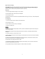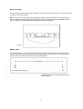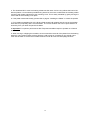
1
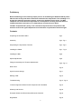
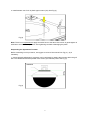
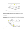
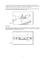
INSTRUCTION MANUAL
Amadeus MK II
Rev. August 2013
1
Preliminary
Before embarking on the relatively simple process of assembling the Amadeus MK II, please
take the time to fully read these instructions and follow the steps within. The old adage of "if
all else fails read the instruction manual" needs to be applied from the onset. The Well
Tempered Lab cannot be held responsible for consequences resulting from the failure to
comprehend these instructions. If in doubt always consult with your dealer.
The Well Tempered Lab’s policy is the continuous improvements of its products. We
therefore reserve the right of departure from illustration or specification that this might
Contents
Unpacking the Amadeus MK II
Pg 3
Assembly
Pg 3 - Pg 4
Suspending the Symmetrex Tonearm
Pg 4 - Pg 6
Installing the Platter
Pg 7 - Pg 8
Installing the Belt
Pg 8
Speed adjustments
Pg 8
Fitting the Cartridge and Tonearm adjustments
Pg 9 - Pg 10
Rear Panel
Pg 10
Stylus Pressure Gauge
Pg 11
Making a Belt
Pg 12
Troubleshooting
Pg 13 - Pg 14
Tonearm Alignment Guide for Well Tempered Lab Turntables
Pg 15
Warranty and Service
Pg 18
European Waste and Electrical and Electronic Directive
Pg 18
Registration
Pg 18
2
Unpacking the Amadeus MK II
We recommend the use of the white gloves provided when handling the plinth and platter
assemblies.
Take care that none of the fluids contaminate the finished surfaces of your Amadeus MK II.
The Amadeus MK II packaging has been designed to protect it from the hazards of shipping. It is
advisable to save it for further use.
Important: Never place a Well Tempered Lab turntable in direct sunlight. Not only will it have
detrimental effects on your valuable recordings, it will impair the mechanical integrity and
performance of your turntable.
Assembly
For ease of assembly we recommend a flat work surface, such as a table or bench. All necessary
tools have been provided.
1. Install bearing cup in plinth adjust to approx 40mm (1.6in) above plinth and tighten set screw. See
Fig (1).
Fig (1)
2. Install tonearm suspension pillar to approx 95mm (3.8in) above plinth and tighten set screw.
Complete with tonearm suspension rod. See Fig (2).
Fig (2)
3
3. Install tonearm rest / lock in plinth approx 50mm (2in). See Fig (3)
Fig (3)
Note: There is no requirement to apply excessive force to the above set screws. A gentle tighten is
sufficient to secure the components. Over tightening can lead to damaging the plinth.
Suspending the Symmetrex Tonearm
Before embarking on this procedure, we suggest a review of the manual from Fig (4) - (9) is
mandatory.
1. Coarse azimuth adjustment if necessary can be achieved by rotating the tonearm within the golf
ball. The Headshell should be parallel to the small nylon filament points. See Fig (4).
Headshell
Parallel
Fig (4)
*Front-on view of Symmetrex tonearm
4
2. With a small amount of care take tonearm and apply one and a half turns of the nylon suspension
from the golf ball around the azimuth adjustment collar. See Fig (5).
Fig (5)
3. Correct bridle length when tonearm is suspended is approximately 25mm from top of tonearm to
bottom of suspension rod. See Fig (6). Apply a clockwise half twist to the azimuth adjustment collar
and install on the suspension rod. The half twist on the nylon suspension effectively applies the
correct “anti-skate”. See Fig (6) - (8). Correct azimuth adjustment is achieved by rotating the azimuth
collar in the directions of the arrows.
Fig (6)
Fig (7)
5
Fig (8)
5. Adjust pillar, rod and azimuth collar to allow golf ball to float central of bearing cup.
Note: All the above adjustments can be fine tuned when cartridge is installed.
Fig (7)
6. Fit tonearm connector to socket making sure that the connector "locks" in place, failure to ensure
this connector is firmly locked may result in a loss of signal on either channel. See Fig (9)
Fig (9)
6
Installing the Platter
Please ensure that the point of the triangle hold in the upper teflon bearing is correctly orientated to
the motor pulley. See Fig (10). If necessary consult your dealer.
Fill the bearing with synthetic oil supplied to a level of approx 5mm (1/4”) above the bottom Teflon
bearing, this is not critical. Do not overfill. Over-filling the bearing will cause the oil to overflow the
bearing housing when the platter spindle is lowered into the bearing housing. Gently lower platter into
bearing. See Fig (11) - (12). It is most important that spindle is located correctly in the centre of the
lower thrust bearing. Failure to locate the pivot point of the spindle correctly will cause the platter to
rotate abnormally. The spindle has been designed to protrude through the platter to provide a central
lifting point that enables the user to easily achieve this.
Important: The unique design of the zero clearance Well Tempered Lab top bearing allows the
spindle to be virtually “free standing”. It is perfectly normal for the platter to tilt away from the motor
when the belt has not been installed.
Should there be any necessity to replace the bearing oil, any synthetic motor oil of any brand within a
viscosity range of 5W-50 is acceptable.
Note: The zero clearance Well Tempered bearing can rotate for hours without oil. If you wish, you
can complete other adjustments before applying the bearing oil. See Fig (10).
Fig (10)
Fig (11)
7
Fig (12)
Speed Control
Speed change is effected by manual movement of the belt on the pulley. 33.5 RPM on the small
diameter step on the pulley, 45 RPM on the larger diameter step on the pulley.
Installing the Belt
Start with the belt around the motor pulley, take care the other end clears the centre spindle and
rotate the platter, the belt will track around the platter. See Fig (13). Well Tempered Lab belts if
dropped are easily misplaced, we give you two but suggest you place the belt on something dark to
make it easily seen.
Fig (13)
Speed Adjustment
This is factory set, but if required, this can be achieved by carefully adjusting the small screw
adjacent to the DC socket.
8
Fitting the Cartridge and Symmetrex Tonearm adjustments
1. We recommend fitting the cartridge with the tone arm in position. However it is possible to fit the
cartridge before suspending the tone arm (see Fig 14). Great care needs to be taken when installing
the cartridge as the Well Tempered Lab bears no responsibility for cartridge damage.
Fig (14)
2. Install the cartridge to the manufacturer’s specifications. The Amadeus MK II features a head shell
that requires no tracking alignment adjustment. We strongly recommend it remains firmly fixed in the
correct position as supplied.
3. The Amadeus MK II Symmetrex tonearm has an effective length of 10.5” (267 mm). The headshell
is fixed ex-factory in the optimum position. There is no provision for over-hang adjustment. Some
alignment protractors may well disagree. However, The Well Tempered Lab stands by their
convictions.
Important: There is absolutely no reason to torque headshell/cartridge mounting hardware to
excess. Cartridge mounting hardware only requires firm but gentle tightening. Heavy handed
torquing of mounting hardware can result in movement of the Amadeus headshell (refer to
www.welltemperedlab.net on tracking geometry).
4. There is an optional finger lift provided which can be attached to the cartridge fixing screw,
adjacent to the right hand side of the plinth.
5. Apply enough damping fluid so as that no more than one third of the golf ball is submerged in fluid.
See Fig (15).
Note: Damping can be altered by simply raising or lowering the damping cup, it is not critical and
maybe adjusted to suit the listener’s own preference.
6. Set tracking force with stylus gauge, supplied to cartridge manufacturer’s specification.
7. To set tracking force, two counterweights are supplied to enable correct tracking force to be
applied to cartridges of various weights. We recommend choice of counterweight (s) that allow
correct tracking force to be obtained with weight (s) as close to the tonearm lead out cable as
practicable. This is not critical but care needs to be taken as to not damage tone-arm lead out cable
when attaching counterweights to tone-arm.
8. Adjust tonearm for correct VTA by set screw on suspension pillar.
9
9. Correct Azimuth can be obtained by gently rotating the azimuth adjustment collar to allow the
cartridge to track parallel to the record surface. This can be achieved whilst the record is rotating and
requires only minor correction in both directions to achieve the correct result.
10. Due to the viscosity of the damping fluid adjustments in both tracking force and azimuth require
the tonearm to momentarily “settle” to effect the correct results.
Fig (15)
Rear Panel
Earth screw and phono sockets colour coded and clearly marked are on the rear panel. See Fig (16).
Speed adjustment is also available on this panel. Connection for the AC adaptor is on this panel and
clearly marked. Plug it in, you are ready to go. Enjoy!
Fig (16)
10
Stylus Pressure Gauge
Fitting Batteries: When fitting the batteries in the Stylus Pressure Gauge, the positive symbol on
both batteries should face upwards when viewed from underside of the Stylus Pressure Gauge i.e.
positive symbol on battery faces upwards and under the opening.
Operation:
1. Place the Stylus Pressure Gauge on a firm surface.
2. Press ON/OFF switch, wait until (0.0) is displayed.
3. Place Stylus on scale.
4. Press the "M" button to shift the unit properties between Gram (g), Ounce (oz), Pennyweight (dwt)
and Carat (ct).
Tare Weighing:
1. Turn on the Stylus Pressure Gauge as described above.
2. Place Stylus on scale.
3. Press "TARE" and wait until (0.0) is displayed.
4. Add the net weight item.
Caution
1. If the Stylus Pressure Gauge displays "OUTZ", please re-calibrate the Stylus Pressure Gauge as
outlined in the manual.
2. Never load the Stylus Pressure Gauge past maximum capacity, overloading will permanently
damage it.
3. Avoid any exposure to extreme heat or cold.
4. When switching the Stylus Pressure Gauge on, please allow 30 seconds for the meter to stabilize
before calibration.
5. Please keep the Stylus Pressure Gauge in a clean environment, avoid dirt and moisture as this
may cause an adverse effect on reliability and accuracy.
6. Handle with care, gently place items on scale .
7. Avoid shaking, dropping or shocking the Stylus Pressure Gauge. This is a precision instrument
and must be operated with extreme care.
8. Only operate the Stylus Pressure Gauge on a stable, vibration free surface.
11
DC Power Supply
We recommend a power supply with a maximum output of 12V and not less than 7V, with a minimum
of 100mA, centre pin positive.
Note: Some switch mode type power supplies can cause grounding problems. A small accessory
lead is supplied to enable the ground connection from the 12V input socket to be established. See
Fig (17). This is not necessarily a Well Tempered Lab recommendation.
Fig (17)
Making a Belt
Loop a long length of 0.004” polyester monofilament around the thumbtack. Tie a simple double
overhand knot around the pin. Remove the pin and tighten the knot. Hold knot with thumbnail and
pull on excess. Cut off excess leaving 10mm (minimum) tails.
21 3/8” (539mm)
Thumbtack (Drawing Pin)
Pin
Cardboard, black for white polyester, white for
black polyester
12
Troubleshooting
1. In the unlikely event that you wish to remove the Symmetrex tonearm, the golf ball can be lifted
clear of the fluid, and left to drain. Surplus fluids may then be wiped from the golf ball with a paper
towel.
2. Rubbing alcohol of 70% or above proof will remove all traces of fluid. All paper towels must be
immediately discarded in a suitable receptacle. We also have it on good authority that Vodka of the
highest proof can be pressed into service if rubbing alcohol is unavailable. Our chief designer also
uses “Ronsonol” brand cigarette lighter fluid with excellent results. This is also known in some
countries as white spirits or white gas. We suggest you first try cleaning fluid with caution and or the
underside of the plinth. The Well Tempered Lab can bear no responsibility for damage caused by
cleaning fluid.
3. Well Tempered Lab belts are easily lost. We recommend placing or hanging on a dark
background, when not on the turntable.
4. For cartridges without threaded fixing holes we find it most convenient to attach the cartridge to the
head shell in the slot closest to the platter. The other screw with the optional finger lift attached can
then be passed through the head shell and remaining cartridge hole. A small "popsicle" stick or
similar with a piece of double backed sticky tape on the end is invaluable. Just place the remaining
cartridge nut on the tape at the end of the stick under the protruding screw and tighten.
Note: Some cartridges may necessitate the shortening of the Nylon bridle that suspends the Golf
Ball. This can easily be achieved by the removal of one of the small plastic tubes that the Nylon
passes through. Removal of this tube will allow excess nylon to be pulled through the tube when the
correct height is obtained the tube can be re-inserted and the excess Nylon removed with a sharp
Trim excess
Golf Ball
Tube
Fig (18)
13
Nylon
5. The Amadeus MK II motor has bearing tolerances that cause it to be noisy without the load of the
belt and platter. It is sometimes possible during transit for the motor to shift within the isolating rubber
mounting and vibrate against the motor mounting cover. This is easily remedied by gently moving the
motor clear of the mounting cover plate.
6. If the platter rotates abnormally, please refer to page 8 “Installing the Platter” to centre the spindle.
7. For Amadeus turntables prior to the factory fitted squash ball isolation feet the use of the isolation
base with four proprietary feet is recommended . The current isolation feet can be purchased as an
accessory from your Well Tempered Lab dealer.
8. Important: For optimum performance Well Tempered turntables require to operate on a flat and
level surface.
9. When moving or shipping the turntable, we recommend the removal of the platter from the bearing
assembly. Care must be taken as there will be a small amount of oil residue on the spindle. Care
must also be taken to ensure the turntable remains level at all times to avoid spillage of fluids.
14
150mm
1. Light Cardboard
2. Center Line of Tone Arm Tube
3. 19˚ Head Shell Angle
19˚
3
Headshell Alignment Guide For Well Tempered Turntables
1
2
20mm
Note: The Headshell is factory fixed in position. Well Tempered Lab
unoquivocally reiterate that it should not be moved.
Heavy handed mounting of the cartridge may result in moving the head shell. In which case place the
above guide with center line parallel to tone arm tube and align head shell to 19˚ angle.
It will be necessary to gently but firmly retighten the small screw fixing the headshell to the
tonearm. Do not overtighten this screw.
15
WARRANTY & SERVICE
Valid on completion of warranty card and confirmed date or purchase. Details can be registered at
www.welltemperedlab.net
This Well Tempered Lab product is warranted against defects in material and workmanship for one
year from date of purchase.
This warranty does not cover normal wear and tear and is void if the Well Tempered product has
been subject to mis-use, accident or negligence or if it has been tampered with or modified in anyway. Spillage of any fluids supplied by the Well Tempered Lab is not covered within the scope of this
warranty.
Warranty is restricted to the territory in which the product was purchased. Our distributors and dealers are under contractual obligation to service under warranty products only sold through them.
They are entitled to make a non refundable charge for service to products purchased outside the territory if required.
Claims Under This Warranty
The product should be returned to the dealer or nearest Well Tempered distributor, complete with
warranty card and confirmed date of purchase. Note special care is required with the fluids and
the Well Tempered Lab and its agents can bear no responsibility for spillage or damage
caused by incorrect handling and packaging of the fluids.
The European Waste Electrical and Electronic Directive
This product can be recycled. Products bearing this symbol must NOT be thrown
away with normal household waste. At the end of the product's life, take it to a collection point designated for recycling of electrical and electronic devices. Find out
more about return and collection points through your local authority.
The European Waste Electrical and Electronic (WEEE) Directive was implemented
to dramatically reduce the amount of waste going to landfills, there by reducing the
environmental impact on the planet and on human health. Please act responsibly
by recycling used products. If this product is still useable, consider giving it away or
selling it.
REGISTRATION CARD
Name
Address
City
State
Telephone
Email
Model
Serial Number
Dealer
____________________________________________________
____________________________________________________
____________________________________________________
____________________________________________________
___________________________ Post Code (Zip)___________
____________________________________________________
____________________________________________________
____________________________________________________
___________________________ Date of Purchase __________
____________________________________________________
16