1
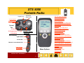
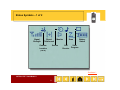
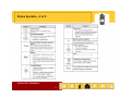
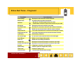
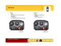
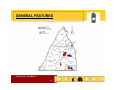
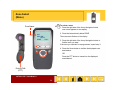
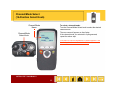
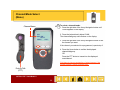
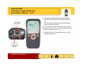
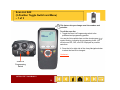
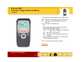
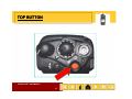
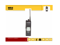
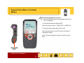
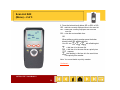
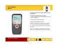
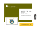
FRANKLIN COUNTY PA CENTER FOR
EMERGENCY SERVICES DIGITAL
RADIO SYSTEM
ASTRO® XTS™ 5000 Model II
1
Cover
®
ASTRO XTS 5000
Model II
TM
Digital Portable Radio
Interactive End-User Training
Franklin County Police User’s
ASTRO® XTS™ 5000 Model II
2
Copyrights/Disclaimer
Computer Software Copyrights
Documentation Copyrights
The Motorola products described in this manual may
No duplication or distribution of this document or any portion thereof
include copyrighted Motorola computer programs stored in
shall take place without the express written permission of Motorola
Motorola.
semiconductor memories or other media. Laws in the
No part of this manual may be reproduced, distributed, or
United States and other countries preserve for Motorola
transmitted in any form or by any means, electronic or mechanical,
certain exclusive rights for copyrighted computer
for any purpose without the express written permission of Motorola.
programs, including, but not limited to, the exclusive right
to copy or reproduce in any form the copyrighted computer
Disclaimer
program. Accordingly, any copyrighted Motorola computer
The information in this document is carefully examined, and is
programs contained in the Motorola products described in
believed to be entirely reliable. However no responsibility is
this manual may not be copied, reproduced, modified,
assumed for inaccuracies. Furthermore, Motorola reserves the right
g
reverse-engineered, or distributed in any manner without
to make changes to any products herein to improve readability,
the express written permission of Motorola. Furthermore,
function, or design. Motorola does not assume any liability arising
the purchase of Motorola products shall not be deemed to
out of the applications or use of any product or circuit described
grant either directly or by implication, estoppel, or
herein; nor does it cover any license under its patent rights nor the
otherwise,
h
i
any lilicense under
d the
h copyrights,
i h patents or
rights of others.
patent applications of Motorola, except for the normal nonexclusive license to use that arises by operation of law in
the sale of a product.
MOTOROLA, the Stylized M Logo, ASTRO, SmartZone, and Spectra are registered in
the US Patent & Trademark Office. Call Alert, intelligence everywhere, Private Call,
Private Conversation, TalkAround, and XTS are trademarks of Motorola, Inc. All other
product or service names are the property of their respective owners.
© Motorola, Inc. 2002.
ASTRO® XTS™ 5000 Model II
3
Welcome
This tutorial has been prepared exclusively for you,
keeping in mind your system configuration and radio
layout. The explanation for each function is a step-by-step
guiding process, specifically designed for easy
comprehension and implementation. However, for indepth system or radio information, you should consult
your system administrator. Keep in mind that each radio
and each system is customer configurable.
ASTRO® XTS™ 5000 Model II
4
XTS 5000 Model II
Getting Started
Z1
Your Radio
Z2
C1
C2
Fleet Map
Installation and
Removal
Status Alert
Tones
Analog and Digital
Audio Quality
ASTRO® XTS™ 5000 Model II
5
Status Symbols
Important Safety
Information
XTS 5000
Portable Radio
Keypad Lock
16-Position
Select Knob
Power On/Off
Volume Control
10 : 46AM
POL
DISP NW
MUTE
ZONE
CALL
Control
Top
A- No Scan
B- Program Scan
Emergency Button
(1 sec delay)
C-Scan Mode
Side Buttons
Light Control
Volume Set
Monitor in conventional Only
Push-To-Talk
(PTT) Button
Menu Options
ASTRO® XTS™ 5000 Model II
6
Call Alert Page (Respond)
Call Alert Page (Send)
Channel/ Mode Select
Clock (Time and Date)
Direct/TalkAround
ID Number (View Your) Using CALL
ID Number (View Your) Using PAGE
Keypad Tones
List View
Nuisance Delete (DEL Menu)
Nuisance Delete (NUIS Menu)
Outdoor Location (GPS)
Phone Call (Place)
Phone Call (Respond)
Power Select
Private Conversation Call (Place)
Private Conversation
C
C
Call ((Respond))
Reprogram Request
Scan On/Off
Scan List Edit (Menu)
Scan List Edit (Menu + Top Button)
Scan List Edit (Menu + Top Side Button)
S
Scan
List
Li Edi
Edit (M
(Menu + Sid
Side Button
B
1)
Scan List Edit (Menu + Side Button 2)
Site Lock
Site View/Search
Smart Battery
Status/Message Calls
T lk
Talkgroup
C
Calls
ll
Zone Select
Status Symbols – 1 of 2
Signal
Strength
Direct/
TalkAround
Outdoor
Location
(GPS)
Monitor
Secure
Scan
Call
Receive
Battery
Status
View
Program
Continued....
ASTRO® XTS™ 5000 Model II
8
Status Symbols – 2 of 2
ASTRO® XTS™ 5000 Model II
9
Status Alert Tones
Tone Name
Tone Information
Acknowledge
Receipt of a call sent to the central controller
Button Press
A valid key was pressed on the keypad
Call Alert
- Receipt of a Call Alert page sent to your radio
- Confirmation receipt of a page received sent from your radio
Emergency
Emergency alarm was sent from your radio
Failsoft
Radio has lost communication with the central controller
Low Battery
Weak battery indication
No Acknowledge
A call to the central controller was not acknowledged
Out of Range
Radio is out of range of the system
Power-up
Radio has successfully powered on
Private Call I
Receipt of a Private Conversation call sent to your radio
Private Call Enhanced
Receipt of a Private Conversation call sent to your radio
Prohibit
Talkgroup or channel is not accessible
System Busy
Channel, system or target radio is busy
Talk Permit
Channel is ready to use
Time-out Timer
Time-out timer limit has been reached
ASTRO® XTS™ 5000 Model II
10
Status Alert Tones – Fireground
Tone Name
Tone Information
Acknowledge
Receipt of a call sent to the central controller
Button Press
A valid key was pressed on the keypad
Call Alert
- Receipt of a Call Alert page sent to your radio
- Confirmation receipt of a page received sent from your radio
Emergency
Emergency alarm was sent from your radio
Evacuation Alert
Receipt of an evacuation alert from the Incident Commander
Failsoft
Radio has lost communication with the central controller
Fireground Fail
Your radio information was not sent to the Command Terminal
Fireground Success
Your radio information was sent to the Command Terminal
Low Battery
Weak battery indication
N A
No
Acknowledge
k
l d
A call
ll to
t the
th central
t l controller
t ll was nott acknowledged
k
l d d
Out of Range
Radio is out of range of the system
Power-up
Radio has successfully powered on
Private Call I
Receipt of a Private Conversation call sent to your radio
P i t Call
Private
C ll Enhanced
E h
d
R
Receipt
i t off a P
Private
i t Conversation
C
ti call
ll sentt to
t your radio
di
Prohibit
Talkgroup or channel is not accessible
System Busy
Channel, system or target radio is busy
Talk Permit
Channel is ready to use
Time out Timer
Time-out
Time out timer limit has been reached
Time-out
ASTRO® XTS™ 5000 Model II
11
LED Status
RED
GREEN
• Solid
- PTT is pressed; radio is transmitting
• Flashing
- Channel Busy
- Low Battery (lights while transmitting)
• Solid
- Self-test being performed
• Flashing
- Incoming Private Call
RED LED
GREEN LED
ASTRO® XTS™ 5000 Model II
12
Installation and
Removal Procedures
Belt Clip
Battery
Antenna
Universal Connector
RF Adapter
p
Public Safety
Speaker
p
Microphone
p
ASTRO® XTS™ 5000 Model II
13
Antenna
To install the antenna:
1. Turn the radio off.
2. Screw the antenna (clockwise) into the antenna
receptacle on top of the radio.
3. Tighten the antenna firmly with your fingers.
To remove the antenna:
1. Turn the radio off.
2. Unscrew the antenna (counter-clockwise) and remove
it from the antenna receptacle on top of the radio.
ASTRO® XTS™ 5000 Model II
14
Charging the Battery
The battery must be charged before use. Memory
effect is a phenomenon that causes a loss in battery
capacity or voltage due to repetitive shallow
discharging or long-term overcharging. This memory
effect has been greatly reduced in your batteries
through the use of new cell technology. It is still
recommended, however, that you discharge your
battery as much as possible before recharging it.
Recharging after each shift is good standard practice.
When charging a battery that is attached to your radio,
turn the radio off to ensure a full charge.
Battery procedures continued on next panel.
ASTRO® XTS™ 5000 Model II
15
Battery
To install the battery:
1. Turn the radio off
2. Hold the radio with the back facing upward.
3. Align the three slots at the top of the battery with the
three tabs on the back of the radio.
4. Push the battery down toward the radio until the battery
clicks into place.
To remove the battery:
1. Turn the radio off.
2. Hold the radio with the back of the radio facing upward.
3. Push the battery release button on the bottom of the
radio.
4. Lift the battery away from the radio and remove.
ASTRO® XTS™ 5000 Model II
16
Universal Connector Cover
The universal connector cover protects the side
connector near the antenna.
To remove the cover:
1. Turn the radio off.
2. Carefully insert a flat-bladed screwdriver between the
bottom of the cover and the connector.
3. Holding the top of the cover with your thumb, push the
screwdriver gently downward and lever the cover away
from the radio.
To install the cover:
1. Turn the radio off.
2. Insert the hooked end of the cover into the slot above
the connector.
3. Rub the ball of your thumb from the top to the bottom
of the cover, applying pressure towards the radio. This
will flex the cover and snap it into place.
ASTRO® XTS™ 5000 Model II
17
Belt Clip
To install the belt clip:
1. Remove the battery before installing or removing the
belt clip.
2. Hold the battery with the back of the battery facing
you.
p with the top
p facing
g upward,
p
and align
g
3. Hold the belt clip
the clip with the slots on the battery back.
4. Slide the belt clip downward into the slots until it clicks
into place.
1
To remove the belt clip:
1. Pull away the metal tab at the top of the battery clip
from the battery.
2
2. Slide the clip upward until it comes away from the
radio.
ASTRO® XTS™ 5000 Model II
18
Public Safety
Speaker/Microphone
(PSSM) – 1 of 3
To install the PSSM:
1. Turn the radio off.
2. Follow the instructions for removing the universal
connector cover.
3. Attach the accessory connector to the radio’s universal
connector as follows:
a. Make sure the RF adapter has been installed in
your radio before continuing with installation.
b. Looking at the antenna side of the radio, insert the
bottom hooked end of the accessory connector into
the slot below the universal connector
connector.
c. While holding the accessory connector seated in
the bottom slot, pivot the top of the accessory
connector toward the radio until its RF interface
connector aligns with the circular contact target on
the RF adapter
adapter, then engage the accessory
connector’s spring-loaded latch in the radio’s top
slot.
Continued....
ASTRO® XTS™ 5000 Model II
19
Public Safety
Speaker/Microphone
(PSSM) – 2 of 3
4. Attach the correct (frequency-sensitive) antenna to the
PSSM by screwing the antenna’s threaded end into the
threaded antenna jack on top of the PSSM’s housing.
5. Rotate the antenna clockwise into the jack until it seats
firmly.
The public safety speaker/microphone performs best
when it is operated with the antenna above the user’s
shoulder.
To transmit using the public safety speaker/microphone,
press the PSSM’s PTT and speak into the microphone’s
grille area. The red light-emitting diode (LED) on top of the
radio will light, indicating that the radio is in the transmit
mode.
If a more permanent attachment is desired after the
accessory connector is latched to the radio, secure the
latch to the connector housing using the screw supplied.
Continued....
ASTRO® XTS™ 5000 Model II
20
Public Safety
Speaker/Microphone
(PSSM) – 3 of 3
To remove the PSSM:
1. Turn the radio off.
2. Rotate the antenna counter-clockwise to unscrew it from
the jack.
3. Remove the accessory connector by pivoting the top of
y connector awayy from the radio until it
the accessory
disengages from the RF adapter.
4. Follow the instructions for attaching the universal
connector cover.
ASTRO® XTS™ 5000 Model II
21
GENERAL FEATURES
ASTRO® XTS™ 5000 Model II
22
Radio On/Off/Volume
To turn the radio on:
Turn the On/Off/Volume Control knob clockwise.
On/Off/Volume
Knob
SELF TEST
If the power-up test is successful, you briefly see SELF
TEST, then the home display. If enabled, a power-up
tone is also heard.
If the power-up test is unsuccessful, you see ERROR
XX/YY (XX/YY is an alphanumeric code.)
XX/YY.
code )
Click here to view further explanation of specific codes.
To turn the radio off:
Turn the On/Off/Volume Control knob counter-clockwise
until
til it clicks.
li k
ASTRO® XTS™ 5000 Model II
23
Zone Select
(Menu)
To select a zone:
Zone Name
1. Press the right side of the 4-way Navigation button
until ZONE appears on the display.
2. Press the button directly below ZONE.
POL
DISP NW
MUTE
ZONE
CALL
The zone name flashes on the display.
3 Press the right side of the 4-way
3.
4 way Navigation button to
find the zone you want.
If the zone you selected is unprogrammed, repeat step 3.
4. Press the Home button to confirm the displayed zone
and channel
channel.
OR
Press the PTT button to transmit on the displayed
zone/channel.
Push-to-Talk
(PTT)
ASTRO® XTS™ 5000 Model II
24
Channel/Mode Select
(16-Position Select Knob)
Channel/Mode
Name
Channel/Mode
Select Knob
To select a channel/mode:
Turn the Channel/Mode Select knob to select the desired
channel/mode.
The new name will appear on the display.
POL
DISP NW
MUTE
PAGE
CALL
ASTRO® XTS™ 5000 Model II
25
If the channel/mode you selected is unprogrammed,
repeat the above step.
Click here to view an explanation of what happens if the
trunked system’s central controller fails.
Channel/Mode Select
(Menu)
To select a channel/mode:
Channel Name
1. Press the right side of the 4-way Navigation button until
CHAN appears on the display.
2. Press the button directly below CHAN.
The channel/talkgroup name flashes on the display.
POL
DISP NW
MUTE
CHAN
CALL
3 Press the right side of the 4-way Navigation button to find
3.
the channel you want.
If the channel you selected is unprogrammed, repeat step 3.
4. Press the Home button to confirm the displayed
channel/talkgroup.
channel/talkgroup
OR
Press the PTT button to transmit on the displayed
zone/channel.
Click here to view an explanation of what happens if the
trunked system’s central controller fails.
Push-to-Talk
(PTT)
ASTRO® XTS™ 5000 Model II
26
Time-out Timer
The time-out timer turns off your radio’s transmitter.
The timer is set for 60 seconds at the factory, but it
can be programmed from 0 to 7.75 minutes (465
seconds) by a qualified radio technician.
1. Hold down the PTT button longer than the
programmed time.
p
warning
g tone, the
You will hear a low-pitched
transmission will cut off, and the LED will go out until you
release the PTT.
2. Release the PTT button.
g and the timer will reset.
The LED will re-light
LED
3. Press the PTT button to re-transmit. The time-out timer
restarts.
The timer will restart and the LED lights red.
Push-to-Talk
(PTT)
ASTRO® XTS™ 5000 Model II
27
Transmit and Receive
To transmit:
1. Select the desired zone/channel.
2. Listen for ongoing conversations; if the channel
becomes clear, proceed with your call.
3. Press and hold the PTT button to transmit and wait for
g red. When
the “Talk Permit” tone. The LED will light
speaking, keep the microphone 1-2" from your mouth.
Note: If you do not hear a Talk Permit tone, your system
administrator has preprogrammed the tone to be off.
(
)
4. Release the PTT button to receive (listen).
LED
Click here for information on Smart PTT which prevents
you from talking over someone else’s conversation.
Click here for information on what happens if you go out
of range of the system.
Push-to-Talk
(PTT)
ASTRO® XTS™ 5000 Model II
28
3-POSITION TOGGLE SWITCH
ASTRO® XTS™ 5000 Model II
29
Scan On or Off
(3-Position Toggle Switch)
POL
DISP NW
MUTE
PAGE
CALL
The scan feature allows you to monitor traffic on
different channels by scanning a preprogrammed list
of channels. Your radio can have several different
scan lists. These lists must be enabled by a
qualified radio technician.
To turn scan on:
Toggle the Scan switch to the predetermined position to
enable scan.
The scan symbol (
active.
) will be displayed, indicating scan is
To turn scan off:
Toggle the Scan switch to the predetermined position to
disable scan.
The scan symbol (
) will no longer be displayed,
indicating scan has been deactivated.
Scan
Switch
ASTRO® XTS™ 5000 Model II
30
Scan List Edit
(3-Position Toggle Switch and
Top Button/Select) – 1 of 3
This feature lets you change scan list members and
priorities.
To edit the scan list:
1. Toggle the Scan List Programming switch to the
predetermined programming position.
POL
DISP NW
You see the first available item and the view/program (
symbol flashing
flashing, indicating the programming mode
mode.
)
2. Press the left or right side of the 4-way Navigation button
to select the item to be changed.
Continued....
Scan List
Programming
Switch
ASTRO® XTS™ 5000 Model II
31
Scan List Edit
(3-Position Toggle Switch and
Top Button/Select) – 3 of 3
4. Press the left or right side of the 4-way Navigation
button to select more items to be added or deleted.
16-Position
Select Knob
OR
Use the 16-Position Select knob to select additional
items to be added or deleted.
POL
DISP NW
Note: The maximum number of members for a trunking
priority monitor scan list is 15; for a conventional scan list,
15 and
15;
d ffor a talkgroup
t lk
scan list,
li t 10.
10
5. Toggle the Scan List Programming switch out of the
programming position.
Scan List
Programming
Switch
ASTRO® XTS™ 5000 Model II
32
Scan List Edit
(3-Position Toggle Switch and
Top Side Button/Select) – 1 of 3
This feature lets you change scan list members and
priorities.
To edit the scan list:
1. Toggle the Scan List Programming switch to the
predetermined programming position.
POL
DISP NW
You see the first available item and the view/program (
symbol flashing
flashing, indicating the programming mode
mode.
)
2. Press the left or right side of the 4-way Navigation button
to select the item to be changed.
Continued....
Scan List
Programming
Switch
ASTRO® XTS™ 5000 Model II
33
Scan List Edit
(3-Position Toggle Switch and
Top Side Button/Select) – 3 of 3
4. Press the left or right side of the 4-way Navigation
button to select more items to be added or deleted.
16-Position
Select Knob
OR
Use the 16-Position Select knob to select additional
items to be added or deleted.
POL
DISP NW
Note: The maximum number of members for a trunking
priority monitor scan list is 15; for a conventional scan list,
15 and
15;
d ffor a talkgroup
t lk
scan list,
li t 10.
10
5. Toggle the Scan List Programming switch out of the
programming position.
Scan List
Programming
Switch
ASTRO® XTS™ 5000 Model II
34
Scan List Edit
(3-Position Toggle Switch and
Side Button 1/Select) – 1 of 3
This feature lets you change scan list members and
priorities.
To edit the scan list:
1. Toggle the Scan List Programming switch to the
predetermined programming position.
POL
DISP NW
You see the first available item and the view/program (
symbol flashing
flashing, indicating the programming mode
mode.
)
2. Press the left or right side of the 4-way Navigation button
to select the item to be changed.
Continued....
Scan List
Programming
Switch
ASTRO® XTS™ 5000 Model II
35
Scan List Edit
(3-Position Toggle Switch and
Side Button 1/Select) – 3 of 3
4. Press the left or right side of the 4-way Navigation
button to select more items to be added or deleted.
16-Position
Select Knob
OR
Use the 16-Position Select knob to select additional
items to be added or deleted.
POL
DISP NW
Note: The maximum number of members for a trunking
priority monitor scan list is 15; for a conventional scan list,
15 and
15;
d ffor a talkgroup
t lk
scan list,
li t 10.
10
5. Toggle the Scan List Programming switch out of the
programming position.
Scan List
Programming
Switch
ASTRO® XTS™ 5000 Model II
36
Scan List Edit
(3-Position Toggle Switch and
Side Button 2/Select) – 1 of 3
This feature lets you change scan list members and
priorities.
To edit the scan list:
1. Toggle the Scan List Programming switch to the
predetermined programming position.
POL
DISP NW
You see the first available item and the view/program (
symbol flashing
flashing, indicating the programming mode
mode.
)
2. Press the left or right side of the 4-way Navigation button
to select the item to be changed.
Continued....
Scan List
Programming
Switch
ASTRO® XTS™ 5000 Model II
37
Scan List Edit
(3-Position Toggle Switch and
Side Button 2/Select) – 3 of 3
4. Press the left or right side of the 4-way Navigation
button to select more items to be added or deleted.
16-Position
Select Knob
OR
Use the 16-Position Select knob to select additional
items to be added or deleted.
POL
DISP NW
Note: The maximum number of members for a trunking
priority monitor scan list is 15; for a conventional scan list,
15 and
15;
d ffor a talkgroup
t lk
scan list,
li t 10.
10
5. Toggle the Scan List Programming switch out of the
programming position.
Scan List
Programming
Switch
ASTRO® XTS™ 5000 Model II
38
Scan List Edit
(3-Position Toggle Switch and Menu)
– 1 of 3
This feature lets you change scan list members and
priorities.
To edit the scan list:
1. Toggle the Scan List Programming switch to the
predetermined programming position.
POL
DISP NW
You see the first available item and the view/program (
symbol flashing
flashing, indicating the programming mode
mode. You
will also see SEL, DEL, and RCL displayed as possible
selections.
)
2. Press the left or right side of the 4-way Navigation button
g
to select the item to be changed.
Continued....
Scan List
Programming
Switch
ASTRO® XTS™ 5000 Model II
39
Scan List Edit
(3-Position Toggle Switch and Menu)
– 2 of 3
3. Press the button directly below SEL or DEL or RCL.
SEL = add the currently displayed item to the scan list.
DEL = delete the currently displayed item from the
scan list.
RCL = view the next available item.
POL
DISP NW
DEL
SEL
RCL
OR
When adding a priority member press the button
di tl b
directly
below
l
SEL additional
dditi
l titimes.
You will see
or
or
with a flashing dot.
= this item is in the scan list.
= this item is in the scan list as a priority-two
member.
b
(dot flashing) = this item is in the scan list as
the priority-one member.
Note: You cannot delete a priority member.
Continued....
ASTRO® XTS™ 5000 Model II
40
Scan List Edit
(3-Position Toggle Switch and Menu)
– 3 of 3
4. Press the left or right side of the 4-way Navigation
button to select more items to be added or deleted.
OR
16-Position
Select Knob
Use the 16-Position Select knob to select additional
items to be added or deleted.
POL
DISP NW
Note: The maximum number of members for a trunking
priority monitor scan list is 15; for a conventional scan list,
15 and
15;
d ffor a talkgroup
t lk
scan list,
li t 10.
10
5. Toggle the Scan List Programming switch out of the
programming position.
Scan List
Programming
Switch
ASTRO® XTS™ 5000 Model II
41
2-POSITION CONCENTRIC SWITCH
ASTRO® XTS™ 5000 Model II
42
TOP BUTTON
ASTRO® XTS™ 5000 Model II
43
Emergency – Send
(Top Button) – 1 of 5
There are three ways to send an emergency signal
from your radio.
EMERGENCY
MUTE
PAGE
CALL
Send an
emergency alarm.
Send
S
d a silent
il t
emergency alarm.
Emergency
Button
(1 Second Delay)
Send
S
d an
emergency call.
Click here for additional information about the Emergency
feature.
ASTRO® XTS™ 5000 Model II
44
Emergency – Send
Emergency Alarm
(Top Button) – 2 of 5
To send an emergency alarm:
1. With the radio turned on, press the Emergency button.
EMERGENCY
MUTE
PAGE
CALL
The current zone/channel is displayed alternately with
EMERGENCY, the LED lights red, and you hear a group
of short, medium-pitched tones.
If the selected channel does not support emergency, the
display shows NO EMERGENCY. Select a channel that
does sho
show EMERGENCY
EMERGENCY.
Note: To exit emergency at any time, press and hold
the Emergency button for about a second.
2 When you receive the dispatcher
2.
dispatcher’s
s acknowledgment,
acknowledgment
you see ACK RECEIVED, four tones sound, the alarm
ends, and the radio exits the emergency mode.
If no acknowledgment is received, you see NO
ACKNOWLDG, the alarm ends, and the radio exits the
emergency mode
mode.
LED
Emergency
Button
ASTRO® XTS™ 5000 Model II
45
SIDE BUTTON 1
ASTRO® XTS™ 5000 Model II
46
Display Light
(Side Button 1)
If poor light conditions make the display or
channel numbers (around the 16-Position Select
knob) difficult to read:
Light
Li
ht
Button
Turn on the radio’s backlights by pressing the Light
button.
These lights will remain on for a preprogrammed time
y turn off automatically.
y
before they
OR
You can turn them off immediately by pressing the Light
button again.
ASTRO® XTS™ 5000 Model II
47
SIDE BUTTON 2
ASTRO® XTS™ 5000 Model II
48
Volume Set Tone
(Side Button 2)
To adjust the volume:
Volume Set
Button
1. Select the desired zone and channel.
2. Press and hold the Volume Set button to hear the
volume set tone.
On/Off/Volume
Knob
3. Adjust the Volume Control knob if necessary.
4. Release the Volume Set button.
ASTRO® XTS™ 5000 Model II
49
Monitor (Conventional)
(Side Button 3)
Your radio may be programmed to receive Private
Line (PL) calls.
Monitor
Button
To enable the monitor feature:
1. Select a conventional channel from the fleet map list
provided by your system administrator.
CONVENTIONAL
y press
p
the Monitor button to listen for activity.
y
2. Momentarily
The monitor/carrier squelch indicator (
) is displayed.
3. Press and hold the Monitor button (for a preset amount
of time) to set continuous monitor operation.
Note: The duration of the button press has been
preprogrammed. Please see your System Administrator.
4. Press the Monitor button again, or the PTT button, to
return to the original squelch setting.
Note: If you try to transmit on a receive-only
receive only channel
channel, you
will hear an invalid tone until you release the PTT button.
Push-to-Talk
(PTT)
ASTRO® XTS™ 5000 Model II
50
MENU
ASTRO® XTS™ 5000 Model II
51
Clock (Time and Date)
(Menu) – 1 of 2
Using this special feature, you can program the time
and date as you might with other electronic devices.
The clock display is enabled by a qualified radio
technician.
10 : 46AM
POL
DISP NW
MUTE
CLCK
CALL
To edit the time and date:
1. Press the right side of the 4-way Navigation button until
CLCK iis di
displayed.
l
d
2. Press the button directly below CLCK.
The current setting is displayed.
3. Press the button directly below EDIT.
The first item flashes.
Continued....
ASTRO® XTS™ 5000 Model II
52
Clock (Time and Date)
(Menu) – 2 of 2
4. Press the up or down arrow of the 4-way Navigation
button to change the selected item.
Note: Press the Home button at any time to return to the
home display without saving your changes.
OR
12HR 03:54AM
MDY 10/31/01
Press the right side of the 4-way Navigation button to
move to an item you wish to change.
SAVE
5. Press the up or down arrow of the 4-way Navigation
button to change the selected item.
6. Press the right side of the 4-way Navigation button one
or more times to move to an item in the date field.
field
7. Press the up or down arrow of the 4-way Navigation
button to change the selected item.
8. When you have made all of your changes, press the
button directly below SAVE to save your changes and
return to the home display.
Note: If a call arrives while the radio is in the clock-setting
menu, the radio exits clock setting, your changes are lost,
and the call information is displayed.
ASTRO® XTS™ 5000 Model II
53
Keypad Tones (Mute or Unmute)
(Menu)
To turn the keypad tones on or off:
1. Press the right side of the 4-way Navigation button until
MUTE is displayed.
displayed
2. Press the button directly below MUTE.
POL
DISP NW
PSWD
MUTE
PHON
The current state is shown – TONES OFF or TONES ON.
3 Press the button directly below OFF or ON
3.
ON.
Note: Press the Home or the PTT button to exit without
changing the setting.
g off keypad
yp tones does not affect any
y other
Note: Turning
tones.
Push-to-Talk
(PTT)
ASTRO® XTS™ 5000 Model II
54
List View
(Menu)
You can use lists to store frequently used numbers
and associate them with names. There are four list
types: call, page, phone, and scan.
To view a list:
POL
DISP NW
PROG
DEL
VIEW
1. Press the right side of the 4-way Navigation button until
VIEW is displayed.
2. Press the button directly below VIEW.
3. Press the left or right side of the 4-way Navigation
button to view the names of available lists.
4 Press the button directly below the name of the list you
4.
wish to view.
You see the first list member and the view/program (
symbol.
5. Press the left or right side of the 4-way
4 way Navigation
button to view other list members.
6. Press the Home button to exit.
Note: If you wish to view a scan list and the list has no
entries,
ti
you see EMPTY LIST.
LIST
ASTRO® XTS™ 5000 Model II
55
)
Nuisance Delete
(DEL Menu)
When the radio scans to a channel that you do not
wish to hear (nuisance channel), you can temporarily
delete the channel from the scan list.
To delete a nuisance channel:
POL
DISP NW
CALL
PHON
DEL
1. Press the right side of the 4-way Navigation button until
DEL is displayed.
2. Press the button directly below DEL to temporarily
delete the displayed channel from the scan list.
3. If desired, re-enable the channel by exiting and reentering scan.
Note: Nuisance delete cannot remove a priority channel
(
) or the last channel in the list.
ASTRO® XTS™ 5000 Model II
56
Nuisance Delete
(NUIS Menu)
When the radio scans to a channel that you do not
wish to hear (nuisance channel), you can temporarily
delete the channel from the scan list.
To delete a nuisance channel:
POL
DISP NW
CALL
PHON
NUIS
1. Press the right side of the 4-way Navigation button until
NUIS is displayed.
2. Press the button directly below NUIS to temporarily
delete the displayed channel from the scan list.
3. If desired, re-enable the channel by exiting and reentering scan.
Note: Nuisance delete cannot remove a priority channel
(
) or the last channel in the list.
ASTRO® XTS™ 5000 Model II
57
Scan List Edit
(Menu) – 2 of 3
6. Press the button directly below SEL or DEL or RCL.
SEL = add the currently displayed item to the scan list.
DEL = delete the currently displayed item from the
scan list.
RCL = view the next available item.
POL
DISP NW
DEL
SEL
RCL
OR
When adding a priority member press the button
directl belo
directly
below SEL additional times
times.
You will see
or
or
with a flashing dot.
= this item is in the scan list.
= this item is in the scan list as a priority-two
member.
b
(dot flashing) = this item is in the scan list as
the priority-one member.
Note: You cannot delete a priority member.
Continued....
ASTRO® XTS™ 5000 Model II
58
Scan List Edit
(Menu and Side Button 1/Select) –
1 of 3
This feature lets you change scan list members and
priorities.
To edit the scan list:
1. Press the right side of the 4-way Navigation button until
PROG is displayed.
POL
DISP NW
CALL
PROG
PHON
y below PROG
2. Press the button directly
You see the lists that can be changed.
3. Press the right side of the 4-way Navigation button until
SCAN is displayed.
4. Press the button directly below SCAN.
You see the first available item and the view/program (
symbol flashing, indicating the programming mode.
)
5. Press the left or right side of the 4-way
4 way Navigation button
to select the item to be changed.
Continued....
ASTRO® XTS™ 5000 Model II
59
Smart Battery
(Menu)
This feature allows you to view the condition of your
Smart Battery.
To access information about your battery:
1. Press the right side of the 4-way Navigation button until
BATT is displayed.
POL
DISP NW
DEL
BATT
RCL
y below BATT.
2. Press the button directly
3. Battery data is displayed as follows:
CAPACITY indicates the current charge on the battery.
INIT indicates the date of the initial use of the battery.
EST CHGS indicates
i di t the
th estimated
ti t d number
b off charges
h
on
the battery.
Note: If a Smart Battery is not powering your radio, the
display will read SMART BATT DATA NOT AVAILABLE.
ASTRO® XTS™ 5000 Model II
60
Talkgroup Calls (Conventional)
(Menu) – 1 of 2
Talkgroup call lets you define a group of conventional
system users so that they can share the use of a
conventional channel.
To select a talkgroup:
POLICE 1
1. Press the right or left side of the 4-way Navigation
button until TGRP is displayed.
MUTE
TGRP
VIEW
2. Press the button directly below TGRP.
You see the last talkgroup that was selected and stored,
and SEL and PSET.
g or left side of the 4-way
y Navigation
g
3. Press the right
button to find the talkgroup you want.
Continued....
ASTRO® XTS™ 5000 Model II
61
Talkgroup Calls (Conventional)
(Menu) – 2 of 2
4. Press the button directly below SEL or PSET.
SEL (SELECT) — Saves the currently displayed talkgroup
p y
and returns to the home display.
PSET (PRESET) — Selects the preset preprogrammed
talkgroup.
POLICE 1
SEL
If the encryption key slaved to the new talkgroup is erased,
you see KEY FAIL displayed and hear a momentary key
fail tone.
PSET
If the encryption key slaved to the new talkgroup is not
allowed, you see ILLEGAL KEY and hear a momentary key
fail tone.
5. Press the Home or PTT button to exit.
Push-to-Talk
(PTT)
ASTRO® XTS™ 5000 Model II
62
Thank You
ASTRO® XTS™ 5000 Model II
63