1
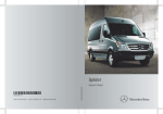
Sprinter
Operator's Manual
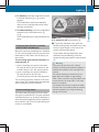
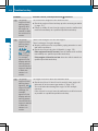
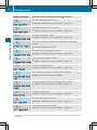
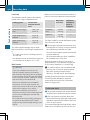
Symbols
$
%
!
+
X
YY
(Y page)
Display
Warning
Environmental note
Possible vehicle damage
Helpful hints or further information
Instructions
Continuation symbol
page reference
Messages in the display
Trademarks®
ESP® is a registered trademark of Daimler.
Vehicle Distributor
Daimler Vans USA LLC
One Mercedes Drive
Montvale, NJ 07645-0350
www.freightlinersprinterusa.com
Customer Assistance Center:
1-877-762-8267
Daimler Vans USA LLC is a Daimler company.
Thank you for choosing the new Sprinter.
Before your first journey, please familiarize
yourself with your vehicle and how it
operates, as well as its driving, control and
convenience functions.
Before you drive off, read this Operator’s
Manual. This will help you to obtain the
maximum pleasure from your vehicle and to
avoid endangering yourself and others.
The equipment or product name for your
vehicle may vary, depending on:
Rmodel
Rorder
Rcountry
specification
Ravailability
Your vehicle's equipment may differ from
some descriptions and illustrations. Items of
optional equipment are also described in this
manual, should you require a description of
the way they work.
The manufacturer continuously updates its
vehicles and equipment. We therefore
reserve the right to make changes with regard
to:
Rdesign
Requipment
Rtechnical
features
Your nearest authorized Sprinter Dealer will
be happy to assist you further if you have any
other questions.
The Operator’s Manual, Brief Instructions,
Service and Warranty Information Booklet,
Maintenance Booklet and equipment-related
supplementary operator’s manuals are
integral parts of the vehicle.
Always keep these manuals in the vehicle.
Pass them on to the new owner if you sell the
vehicle.
We extend our best wishes for many miles of
safe, pleasurable driving.
9065844971 É9065844971@ËÍ
Contents
Index ....................................................... 4
At a glance ........................................... 21
Introduction ......................................... 16
Safety ................................................... 31
Controls ............................................... 51
Operation ........................................... 137
Practical advice ................................ 181
Wheels and tires ............................... 251
Technical data ................................... 275
3
4
Index
1, 2, 3 ...
12 V socket ........................................ 133
A
ABS (Anti-lock Brake System)
Display message ............................ 201
ABS (Anti-lock Braking System)
Function/notes ................................ 47
Accessories and conversions
see Add-on equipment
Active Service System (ASSYST) ..... 167
Add-on equipment ............................. 276
ADR
Working speed governor (ADR) ...... 117
Air bags
Front air bag (driver, front
passenger) ....................................... 39
Important safety notes .................... 38
Safety guidelines ............................. 37
Side impact air bag .......................... 40
Window curtain air bag .................... 41
Air conditioning in the rear
compartment
see Climate control .......................... 97
Air-conditioning system
Air vents in the roof duct ............... 102
Refrigerant ..................................... 161
see Climate control .......................... 97
Air distribution
Setting ........................................... 102
Air filter
Indicator lamp ................................ 195
Airflow
Setting ........................................... 102
Air pressure
see Tire pressure
Air-recirculation mode ...................... 104
Air vents
Setting ........................................... 101
Alarm system
see ATA
Antifreeze additives
see Coolant ................................... 160
Anti-lock Braking System
see ABS
Anti-Theft Alarm system
see ATA
Anti-theft system
ATA (Anti-Theft Alarm system) ......... 61
Armrests .............................................. 68
Ashtray ............................................... 128
ASR (Acceleration Skid Control) ........ 48
Activating/deactivating ................... 49
ASSYST
see Active Service System
(ASSYST) ........................................ 167
ATA (Anti-Theft Alarm)
ATA troubleshooting ...................... 212
ATA (Anti-Theft Alarm system)
Activating/deactivating ................... 62
Function ........................................... 61
Switching off the alarm .................... 62
Audible warning signal ..................... 212
Automatic car wash .......................... 164
Automatic headlamp mode ................ 90
Automatic locking ............................... 55
Automatic transmission ................... 113
Driving tips .................................... 115
Malfunction .................................... 214
Releasing the parking lock
manually ........................................ 246
Shift ranges ................................... 114
Touchshift ...................................... 114
Transmission oil change ................ 158
Auxiliary heater
see Auxiliary heating ...................... 104
Auxiliary heating ............................... 104
Heater booster function ................. 107
malfunction .................................... 216
Switch ............................................ 105
Switch-on time ............................... 106
B
Backup lamp
Changing bulbs ...................... 236, 237
BAS (Brake Assist System) ................. 48
Battery ............................................... 175
Charge indicator lamp ................... 191
Charging ........................................ 178
Disconnecting ................................ 176
Display message ............................ 205
Isolating switch ................................ 87
Index
Notes on care ................................ 179
Reconnecting ................................. 178
Removing/installing ...................... 177
Belt
see Seat belts
Bio-diesel ........................................... 153
Bi-Xenon headlamps
Driving abroad ............................... 138
Brake fluid .......................................... 159
Display message ............................ 205
Fluid change .................................. 159
Fluid level ...................................... 170
Warning lamp ................................. 188
Brake lamp
Changing bulbs ...................... 236, 237
Brake lining
Indicator lamp ................................ 191
Brake linings
Display message ............................ 205
Brakes
ABS .................................................. 47
BAS .................................................. 48
Brake system
Fluid level ...................................... 170
Malfunction .................................... 205
Warning lamp ........................ 187, 188
Breakdown
see Flat tire
Breaking-in ......................................... 138
Bulb failure indicator .......................... 89
C
Camera
see Rear view camera .................... 122
Capacities .......................................... 287
Care of the vehicle ............................ 162
Cargo tie-down ring
Permissible tensile load ................. 283
Cargo tie-down rings ......................... 146
Installing ........................................ 148
CD player/CD changer ........................ 78
Center console ..................................... 26
Central locking .................................... 54
Automatic locking ............................ 55
Malfunction .................................... 217
Central locking system
see Key ............................................ 52
Troubleshooting ............................. 217
Changing bulbs .................................. 233
Display message ............................ 209
Doorway lamp ................................ 238
Exterior lighting ............................. 234
Headlamps ..................................... 234
Indicator and warning lamps .......... 197
Interior light ........................... 238, 239
Perimeter lamp .............................. 238
Tail lamp ................................ 236, 237
Chassis number
see Vehicle identification number .. 277
Child-proof locks
Rear doors ....................................... 45
Children
In the vehicle ................................... 41
Restraint systems ............................ 42
Child seat
LATCH-type (ISOFIX ) child seat
anchors ............................................ 43
Special seat belt retractor ............... 43
Top Tether ....................................... 44
Chock ................................................. 183
Cigarette lighter ................................ 129
Cleaning
After driving off-road or on
construction sites .......................... 165
Alloy wheels ................................... 165
Automatic car wash ....................... 164
Cleaning the engine ....................... 165
High-pressure cleaning .................. 164
Vehicle exterior .............................. 162
Vehicle interior .............................. 162
Cleaning and care .............................. 162
Climate control .................................... 97
Adjusting the air vents ................... 101
Air conditioning in the rear
compartment ................................. 100
Air-conditioning system ................... 99
Air-recirculation mode ................... 104
Control panels ................................. 97
Cooling with air dehumidification . . 100
Defrosting the windows ................. 103
Fogged up windows ....................... 103
General notes .................................. 98
Heating ............................................ 98
5
6
Index
Heating in the rear compartment ..... 99
Rear-compartment air
conditioning ................................... 100
Rear-compartment heating .............. 99
Reheat function (air
dehumidification) ........................... 103
Setting the air distribution ............. 102
Setting the airflow ......................... 102
Setting the temperature ................ 100
Switching air-recirculation mode
in the rear compartment on/off .... 104
Switching on/off ........................... 100
Cockpit ................................................. 22
Combination switch ............................ 90
Consumption statistics (vehicles
with steering wheel buttons) ............. 85
Control panel
Above the windshield ....................... 27
Conversions and accessories
see Add-on equipment
Coolant ............................................... 160
Changing ....................................... 160
Display message ............................ 206
Expansion tank .............................. 169
Level .............................................. 169
Temperature gauge (vehicles with
steering wheel buttons) ................... 77
Topping up ..................................... 169
Warning lamp ................................. 193
Cornering lamps .................................. 91
Changing bulbs .............................. 235
Cruise control .................................... 118
Display message ............................ 203
Malfunction .................................... 216
Cup holder ......................................... 132
D
Daytime running lamp
see Daytime running lamp mode
Daytime running lamp mode .............. 89
Setting (vehicles without steeringwheel buttons) ................................. 74
Setting (vehicles with steering
wheel buttons) ................................. 82
DEF
See Diesel Exhaust Fluid (DEF) ...... 155
Delayed switch-off .............................. 83
Diesel
Consumption ................................. 140
Fuels .............................................. 153
Low outside temperatures ............. 154
Reserve fuel warning lamp ....... 72, 193
Tank capacity ................................. 287
Diesel engine
Preglow indicator lamp .................. 194
Winter driving ................................ 154
Diesel Exhaust Fluid (DEF) ............... 155
Capacities ...................................... 287
Consumption ................................. 140
Display message ........... 199, 202, 204
Exhaust gas aftertreatment ........... 116
Indicator lamp ................................ 190
Level indicator ............................... 116
Ranges ........................................... 116
Refilling .......................................... 143
Storage .......................................... 156
Tool for the tank filler cap .............. 182
Digital speedometer
Setting the unit (vehicles with
steering wheel buttons) ................... 80
Display
Display messages .......................... 197
Outside temperature (vehicles
with steering wheel buttons) ............ 77
Outside temperature display
(vehicles without steering wheel
buttons) ........................................... 73
see Indicator and warning
lamps ....................................... 24, 187
Standard display (vehicles
without steering wheel buttons) ...... 73
Standard display (vehicles with
steering wheel buttons) ................... 77
Distance recorder ................................ 73
see Odometer .................................. 73
Door
Control panel ................................... 28
Door lock
see Central locking .......................... 54
Doors
Display message ............................ 208
Indicator lamp ................................ 197
Opening (from the inside) ................ 56
see Central locking .......................... 54
Unlocking/locking with key ............. 52
Index
Doorway lamp
Changing bulbs .............................. 238
Driver's door and co-driver's door ..... 56
Driving abroad ................................... 138
Driving off-road ................................. 138
Driving on rough terrain
see Driving off-road ....................... 138
Driving safety system
ASR (Acceleration Skid Control) ...... 48
EBD (Electronic Brake force
Distribution) ..................................... 48
ESP® (Electronic Stability
Program) .......................................... 50
Important safety information ........... 47
Driving safety systems
ABS (Anti-lock Braking System) ....... 47
BAS (Brake Assist System) .............. 48
Overview .......................................... 47
Driving system .................................. 117
Malfunctions .................................. 215
Rear view camera .......................... 122
Driving systems
Cruise control ................................ 118
PARKTRONIC ................................. 119
Driving tips ........................................ 138
Driving abroad ............................... 138
Pulling away ................................... 110
Stopping the vehicle and
switching off the engine ................. 111
Towing a trailer .............................. 150
E
EBD (Electronic Brake force
Distribution)
Function/notes ................................ 48
Indicator lamps .............................. 187
Electrical/electronic devices
Communications equipment .......... 133
Electrical/electronic equipment
Retrofitting .................................... 277
Electrical closing assist ...................... 57
Electrical heater booster system ....... 98
Electrical system ................................. 88
Electronic Brake force
see EBD
Electronic Stability Program
see ESP®
e mark ................................................ 277
Emergency equipment ...................... 182
Emergency exit window ..................... 45
Emergency tensioning device
Function ........................................... 35
Safety guidelines ............................. 37
Engine
Check engine indicator lamp ......... 194
Electronics ..................................... 276
Maximum speeds ........................... 280
Wash .............................................. 165
Engine oil ........................................... 156
Adding ........................................... 173
Checking the oil level (on-board
computer) ...................................... 171
Checking the oil level using the
dipstick .......................................... 172
Consumption ................................. 141
Display message ............................ 207
Mixing ............................................ 157
Oil change ...................................... 156
SAE classification .......................... 157
Warning lamp ................................. 192
Engine oil filler neck ......................... 169
Error memory
see Message memory (vehicles
with steering wheel buttons) ............ 78
ESP® (Electronic Stability
Program) .............................................. 50
Exhaust gas aftertreatment ............. 116
DEF capacities ............................... 287
DEF level indicator ......................... 116
DEF reducing agent ............... 116, 155
Diesel Exhaust Fluid (DEF) ............. 155
Display message ........... 199, 202, 204
Indicator lamp ................................ 190
Malfunction ........... 195, 199, 202, 204
Refilling DEF .................................. 143
Exterior lighting
Bulb failure indicator ........................ 89
Changing bulbs .............................. 233
Daytime running lamp mode
(vehicles without steering wheel
buttons) ........................................... 74
Daytime running lamp mode
(vehicles with steering wheel
buttons) ........................................... 82
7
8
Index
Delayed switch-off (vehicles with
steering wheel buttons) ................... 83
Light switch ..................................... 89
Locator lighting (vehicles with
steering wheel buttons) ................... 83
Surround lighting (vehicles with
steering wheel buttons) ................... 83
Exterior mirrors ................................... 70
Eyeglasses compartment ................. 131
F
Fatty acid methyl ester FAME .......... 153
Fire extinguisher ............................... 184
First-aid kit ......................................... 183
flat tire
Notes ............................................. 222
Wheel change ................................ 229
Folding seat ......................................... 67
Folding table ...................................... 132
Front fog lamps ................................... 90
Changing bulbs .............................. 235
Front windshield
see Windshield ............................... 163
Fuel ..................................................... 153
Additives ........................................ 154
Consumption ................................. 140
Display message ............................ 208
Fuel filter with water separator ....... 221
Indicator lamp ................................ 196
Fuel gauge ............................................ 72
Fuel tank content
Reserve, display message .............. 208
Fuses .................................................. 239
Driver's seat fuse box .................... 243
Fuse allocation ...................... 241, 244
Main fuse box ................................ 240
G
General driving tips ........................... 110
Genuine parts .................................... 276
Glove box ........................................... 131
H
Handbrake
see Parking brake .......................... 112
Hazard warning lamps ........................ 91
Headlamp
Cleaning system ...................... 95, 171
Headlamps
Changing bulbs .............................. 234
Cleaning ......................................... 164
Fogged up ...................................... 219
Headlamps, automatic ........................ 90
Head restraints .................................... 67
Heater booster function ................... 107
Heating
see Climate control .......................... 97
High beam flasher ............................... 90
High-beam headlamps ........................ 90
Changing bulbs .............................. 235
High-pressure cleaning ..................... 164
Hood
Opening/closing ............................ 168
I
Ignition lock ......................................... 56
Immobilizer .......................................... 61
Indicator and warning lamps ........... 187
ABS ................................................ 189
Air filter .......................................... 195
ASR ....................................... 187, 189
BAS ....................................... 187, 189
Battery charge ............................... 191
Brakes ........................................... 188
Brake wear .................................... 191
Bulbs .............................................. 197
Check engine ................................. 194
Coolant .......................................... 193
Doors ............................................. 197
Engine oil level ............................... 192
ESP® ...................................... 187, 190
Poly-V-belt ..................................... 191
Preglow .......................................... 194
Reserve fuel ................................... 193
SRS ................................................ 191
Tire pressure monitor .................... 195
Water separator ............................. 196
Windshield washer fluid ................. 196
Indicator lamps
see Warning and indicator
lamps ....................................... 24, 187
Instrument cluster .............................. 70
Lighting ............................................ 72
Index
Speedometer ................................... 71
Tachometer ...................................... 71
Instrument cluster illumination
see Instrument lighting .................... 72
Instrument lighting ............................. 72
Interior light
Changing bulbs ...................... 238, 239
Interior lighting
Changing bulbs .............................. 233
Front ................................................ 92
Rear ................................................. 92
Interior motion sensor ........................ 62
ISOFIX (LATCH-type child seat
securing system) ................................. 43
J
Jack .....................................................
Jacking points ................................
Preparation ....................................
Jump-starting .....................................
Jump-starting connection point in
the engine compartment ..................
182
230
230
247
247
K
Key
Checking the batteries ..................... 53
Malfunction .................................... 217
Kickdown ........................................... 115
L
Lamp
Failure indicator ............................... 89
Language
Display (vehicles with steering
wheel buttons) ................................. 81
Lashing points and materials ........... 146
Lashing points and tie downs
Permissible tensile load ................. 283
License plate lamp
Changing bulbs ...................... 236, 237
Lighting
Bulb failure indicator ........................ 89
Changing bulbs ...................... 233, 234
Instrument ....................................... 72
Light switch ..................................... 89
Lights
Automatic headlamp mode .............. 90
Combination switch ......................... 90
Cornering light function ................... 91
Daytime running lamp
mode ................................... 74, 82, 89
Interior lighting ................................ 92
Light switch ..................................... 89
Load distribution ....................... 146, 152
Loading guidelines ............................ 144
Loads
Securing ........................................ 146
Transporting .................. 144, 146, 152
Locator lighting
Setting (vehicles with steering
wheel buttons) ................................. 83
Locking
Automatic ........................................ 55
With button ...................................... 55
With key ........................................... 52
Locking system
see Central locking .......................... 54
Low-beam headlamps ......................... 89
Automatic headlamps ...................... 90
Changing bulbs .............................. 235
Daytime running lamp mode
(vehicles without steering wheel
buttons) ........................................... 74
Daytime running lamp mode
(vehicles with steering wheel
buttons) ..................................... 74, 82
Driving abroad ............................... 138
M
M+S tires ............................................ 254
Maintenance points under the
hood .................................................... 169
Malfunctions ...................................... 187
Message memory (vehicles with
steering wheel buttons) ................... 78
Maximum speed ................................ 141
Menu (vehicles with steering
wheel buttons)
Audio ............................................... 77
Message memory ............................ 78
Operation ......................................... 76
Settings ........................................... 78
9
10
Index
Telephone ........................................ 86
Trip computer .................................. 85
Message memory (vehicles with
steering wheel buttons) ..................... 78
Messages
Vehicles without steering wheel
buttons .......................................... 199
Vehicles with steering wheel
buttons .......................................... 201
Mirrors
Exterior mirrors ................................ 70
Rear-view mirror .............................. 69
Mobile phone ..................................... 134
Display message ............................ 207
Installation ..................................... 277
Monitor
see Rear view camera .................... 122
O
Occupant safety
Children in the vehicle .....................
System overview ..............................
Odometer
Setting the unit (vehicles with
steering wheel buttons) ...................
On-board computer
Vehicles without steering wheel
buttons ............................................
Vehicles with steering wheel
buttons ............................................
Opening/closing the windows ...........
Outside temperature display
Vehicles without steering wheel
buttons ............................................
Vehicles with steering wheel
buttons ............................................
Overhead control panel
Overview ..........................................
Overrevving range ...............................
Overview
Menus (Vehicles with steering
wheel buttons) .................................
41
32
80
72
74
60
73
77
27
71
76
P
Paint code number ............................ 277
Paper holder ...................................... 131
Parking
see Stopping the vehicle and
switching off the engine ................. 111
Parking aid
see PARKTRONIC
Parking brake .................................... 112
Display message ............................ 206
Parking lamp
Changing bulbs .............................. 235
Parking lamps ...................................... 89
PARKTRONIC ...................................... 119
Activating/deactivating ................. 122
Cleaning the sensors ..................... 163
Indicator lamp ................................ 215
Malfunction .................................... 215
Range of the sensors ..................... 120
Roll-back warning .......................... 122
Trailer towing ................................. 122
Warning display ..................... 121, 215
Partition sliding door .......................... 59
Perimeter lamp
Changing bulbs .............................. 237
Perimeter lamps
Changing bulbs .............................. 238
Poly-V-belt
Malfunction .................................... 191
Power supply
Battery isolating switch .................... 87
Power supply (trailer) ....................... 153
Power windows ................................... 60
Practical advice
Auxiliary heating ............................ 216
Central locking system .................. 217
Engine ............................................ 212
Fuel and fuel tank .......................... 220
Headlamps and turn signals .......... 219
Windshield wipers .......................... 219
Preparing for a journey ..................... 108
Checks in the vehicle ..................... 108
Visual check of the vehicle
exterior .......................................... 108
Index
R
Radio
Changing stations (vehicles with
steering wheel buttons) ................... 77
Cleaning the display ...................... 162
Setting station selection (vehicles
with steering wheel buttons) ............ 84
Rain/light sensor
Setting the sensitivity (vehicles
with steering wheel buttons) ............ 84
Windshield wipers ............................ 94
Range (vehicles with steering
wheel buttons) ..................................... 86
Reading lamp ....................................... 92
Rear bench seat ................................... 66
Rear-compartment air
conditioning
Changing the air filter .................... 173
see Climate control .......................... 97
Rear-compartment heating
see Climate control .......................... 97
Rear doors ............................................ 57
Rear fog lamp ...................................... 90
Changing bulbs ...................... 236, 237
Rear lamp
Changing bulbs ...................... 236, 237
Rear view camera .............................. 122
Malfunction .................................... 216
Monitor menu ................................ 124
Switching off the monitor while
driving ............................................ 128
Switching on .................................. 123
Switching the monitor on/off ........ 123
Rear-view camera
Cleaning ......................................... 163
Cleaning the monitor ..................... 162
Rear-view mirror .................................. 69
Rear window defroster ....................... 95
Rear window heating
Malfunction .................................... 211
Rear window wiper ............................. 94
Refilling
Diesel Exhaust Fluid (DEF) ............. 143
Tool for DEF tank filler cap ............ 182
Refrigerant ......................................... 161
Refueling ............................................ 142
Remote control
see Key ............................................ 52
Replacing bulbs
see Changing bulbs ............... 233, 234
Reserve fuel
Tank ......................................... 72, 193
Restraint system
Display message ............................ 203
Malfunction .................................... 191
Restraint systems
see SRS
Reverse gear
Engaging (automatic
transmission) ................................. 114
Reverse warning feature .................. 141
Rims .................................................... 280
Roll-back warning
see PARKTRONIC ........................... 122
Roof carrier ................................ 149, 284
Roof load (maximum) ........................ 284
Roof rack
see Roof carrier ..................... 149, 284
Roof ventilator in the cargo
compartment ..................................... 108
S
SAE classification (engine oils) ........ 157
Safety
Children in the vehicle ..................... 41
Child restraint systems .................... 42
Overview of occupant safety
systems ........................................... 32
Safety systems
see Driving safety systems
Seat
Co-driver's seat ............................... 63
Driver's seat .................................... 63
Folding seat ..................................... 67
Luxury seat ...................................... 63
Rear bench seat ............................... 66
Standard seat .................................. 63
Suspension seat .............................. 63
Swivel seat ....................................... 65
Twin co-driver's seat ........................ 65
11
12
Index
Seat belt
Cleaning ......................................... 162
Display message ............................ 206
Warning lamp ................................. 196
Seat belts
Adjusting the height ......................... 35
Belt force limiters ............................ 35
Correct usage .................................. 33
Emergency Tensioning Devices ........ 35
Fastening ......................................... 34
Important safety guidelines ............. 32
Releasing ......................................... 35
Safety guidelines ............................. 37
Special seat belt retractor ............... 43
Warning lamp (function) ................... 35
Seat heating ......................................... 68
Malfunction .................................... 211
Selector lever position ...................... 114
Service indicator ............................... 167
Service products
Bio-diesel ....................................... 153
Brake fluid ..................................... 159
Capacities ...................................... 287
Coolant .......................................... 160
Diesel Exhaust Fluid (DEF) ............. 155
Engine oil ....................................... 156
Fuel ................................................ 153
Fuel additive .................................. 154
Fuel additives ................................ 154
Power steering fluid ....................... 159
Refrigerant ..................................... 161
Transmission oil ............................. 158
Settings
Resetting all (vehicles with
steering wheel buttons) ................... 78
Resetting submenus (vehicles
with steering wheel buttons) ............ 79
Setting the clock
Vehicles without steering wheel
buttons ............................................ 73
Setting the date
Vehicles without steering wheel
buttons ............................................ 73
Vehicles with steering wheel
buttons ............................................ 82
Setting the time
Vehicles with steering wheel
buttons ............................................ 82
Shift ranges
Automatic transmission ................. 114
Side impact air bag ............................. 40
Side windows
Resetting ......................................... 61
Sliding door .......................................... 56
Cleaning ......................................... 164
Closing assist ................................... 57
Snow chains ...................................... 255
Socket ................................................ 133
Spare wheel
Bracket .......................................... 184
see Spare wheel ............................ 184
Wheel change ................................ 229
Speed
Setting, see Cruise control ............ 119
Speed limiter ..................................... 141
Speedometer ....................................... 71
Setting the unit (vehicles with
steering wheel buttons) ................... 80
SRS (Supplemental Restraint
System)
Indicator lamp .................................. 36
Introduction ..................................... 36
Standing lamp
Changing bulbs .............. 235, 236, 237
Starting the engine ........................... 109
Steering wheel ..................................... 69
Adjusting ......................................... 69
Buttons (vehicles with steering
wheel buttons) ................................. 74
With buttons .................................... 26
Stowage spaces and stowage
compartments ................................... 129
Eyeglasses compartment ............... 131
Glove box ....................................... 131
Paper holder .................................. 131
Stowage compartment above the
windshield ..................................... 130
Stowage compartment in the
center console ............................... 130
Stowage compartment in the
dashboard ...................................... 129
Stowage compartment in the
door ............................................... 130
Index
Stowage space above the
headliner ........................................ 130
Stowage space under the twin codriver's seat ................................... 130
Submenu (on-board computer)
Clock/Date ...................................... 82
Convenience .................................... 85
Instrument cluster ........................... 80
Lighting ............................................ 82
Selecting .......................................... 79
Settings overview ............................ 79
Vehicle ............................................. 84
Summer tires ..................................... 254
Supplemental Restraint System
see SRS
Surround lighting
Setting (vehicles with steering
wheel buttons) ................................. 83
Switching off the alarm (ATA) ............ 62
Switch unit
Additional ........................................ 28
Center console ................................ 27
Driver's door .................................... 28
Swivel seat ........................................... 65
T
Tachometer .......................................... 71
Tank content
Reserve fuel warning lamp ............. 193
Tank contents ...................................... 72
Range (vehicles with steering
wheel buttons) ................................. 86
Technical data
Capacities ...................................... 287
Speed ............................................ 280
Tire pressure .................................. 281
Tires/wheels ................................. 280
Vehicle dimensions ........................ 280
vehicle weights .............................. 280
Telephone .......................................... 134
Operation (vehicles with steering
wheel buttons) ................................. 86
Temperature
Setting (heating/air conditioning) . 100
Setting the unit (vehicles with
steering wheel buttons) ................... 80
Theft deterrent locking system
Immobilizer ...................................... 61
Tightening torque
Wheel nuts/wheel bolts ................ 232
Time
Setting the time (vehicles without
steering wheel buttons) ................... 73
Setting the time (vehicles with
steering wheel buttons) ................... 82
tire
Wheel change ................................ 229
Tire
Labels ............................................ 279
Tire and Loading Information label .. 279
Tire Inflation Pressure label ............. 279
tire pressure
Calling up (vehicles with steering
wheel buttons) ............................... 260
Tire pressure
Calling up (on-board computer) ..... 258
Checking manually ........................ 258
Display message ........... 199, 203, 208
Maximum ....................................... 257
Recommended ...................... 255, 281
Setting the unit (vehicles with
steering wheel buttons) ................... 81
Tables ............................................ 281
Tire and Loading Information
label ............................................... 279
Tire Inflation Pressure label ........... 279
Tire label ................................ 256, 279
Warning lamp ................................. 195
Tire pressure monitoring system
Function/notes ............................. 258
Tires
Aspect ratio (definition) ................. 270
Average weight of the vehicle
occupants (definition) .................... 269
Bar (definition) ............................... 268
Characteristics .............................. 268
Checking ........................................ 253
Definition of terms ......................... 268
Direction of rotation ...................... 272
Distribution of the vehicle
occupants (definition) .................... 271
DOT, Tire Identification Number
(TIN) ............................................... 268
13
14
Index
DOT (Department of
Transportation) (definition) ............
Flat tire ..........................................
GAWR (Gross Axle Weight Rating)
(definition) .....................................
GVW (Gross Vehicle Weight)
(definition) .....................................
GVWR (Gross Vehicle Weight
Rating) (definition) .........................
Increased vehicle weight due to
optional equipment (definition) ......
Kilopascal (kPa) (definition) ...........
Labeling (overview) ........................
Load bearing index (definition) ......
Maximum loaded vehicle weight
(definition) .....................................
Maximum load on a tire
(definition) .....................................
Maximum permissible tire
pressure (definition) .......................
Maximum tire load .........................
Maximum tire load (definition) .......
Optional equipment weight
(definition) .....................................
PSI (pounds per square inch)
(definition) .....................................
Replacing .......................................
Service life .....................................
Sidewall (definition) .......................
Speed index (definition) .................
Storing ...........................................
Structure and characteristics
(definition) .....................................
TIN (Tire Identification Number)
(definition) .....................................
Tire bead (definition) ......................
Tire pressure (definition) ................
Tire pressures (recommended) ......
Tire size (data) ...............................
Tire size designation, load-bearing
capacity, speed index ....................
Tire tread .......................................
Tire tread (definition) .....................
Total load limit (definition) .............
Traction (definition) .......................
Uniform Tire Quality Grading
Standards (definition) ....................
Unladen weight (definition) ............
269
221
269
269
269
269
270
266
271
270
270
270
265
270
270
270
271
254
270
269
273
268
271
270
270
269
280
266
253
270
271
271
269
270
valve, Snap-In ................................ 252
Wear indicator (definition) ............. 271
Wheel rim (definition) .................... 269
Tires and wheels (important safety
information) ....................................... 252
tire sealant
Storage location ............................ 184
Using ............................................. 222
Tools
see Vehicle tool kit ........................ 182
Top speed
Technical data ............................... 280
Top Tether ............................................ 44
Touchshift .......................................... 114
Tow-away protection .......................... 62
Towing ................................................ 248
Towing a trailer
Driving tips .................................... 150
Towing eye ......................................... 249
Tow-starting ....................................... 248
Trailer
Brake force booster malfunction . . . 188
Coupling up ................................... 150
Decoupling ..................................... 152
Power supply ................................. 153
Towing ........................................... 151
Towing with PARKTRONIC ............. 122
Trailer tow hitch ............................. 284
Trailer coupling
Permitted weights and loads ......... 285
Trailer hitch ....................................... 284
Trailer loads and drawbar
noseweights ...................................... 152
Transmission oil ................................ 158
Transport by rail ................................ 140
Transporting
Load distribution ................... 146, 152
Loading .......................................... 144
Securing a load .............................. 146
Trip computer (vehicles with
steering wheel buttons) ..................... 85
Trip meter ............................................ 73
see Trip odometer
Trip odometer
Resetting ......................................... 72
Index
Troubleshooting
Automatic transmission ................. 214
Driving systems ............................. 215
Turn signals ......................................... 90
Changing bulbs .............. 235, 236, 237
Two-way radio
Installation ..................................... 277
U
Unlocking
With button ...................................... 55
With key ........................................... 52
V
Vehicle
Assemblies .................................... 174
Cleaning ......................................... 162
Dimensions .................................... 280
Electronics ..................................... 276
Individual settings (vehicles with
steering wheel buttons) ................... 78
Loading .......................................... 261
Towing ........................................... 248
Tow-starting ................................... 248
Transporting .................................. 250
Weights .......................................... 280
Vehicle identification number .......... 277
Vehicle identification plates ............ 277
Vehicle key
Malfunction .................................... 217
Vehicle tool kit .................................. 182
Voltage supply
Fuses ............................................. 239
W
Warning and indicator lamp
Diesel Exhaust Fluid (DEF) ............. 190
Warning and indicator lamps ............. 24
PARKTRONIC ................................. 215
Seat belt ........................................ 196
Warning lamp .................................... 182
Warning tones ................................... 212
Warning triangle ....................... 182, 183
Washer fluid
Display message ............................ 208
Indicator lamp ................................ 196
Topping up ..................................... 171
Wiping with ...................................... 95
Wheel
Changing ....................................... 229
Rim size ......................................... 280
Spare wheel ................................... 184
Wheel chock ...................................... 229
Wheel nuts/wheel bolts
Retightening .................................. 233
Tightening torque ........................... 232
Wheels
Changing/replacing ....................... 271
Checking ........................................ 253
Storing ........................................... 273
Wheel size/tire size ....................... 280
Window curtain air bag ....................... 41
Windows
Cleaning ......................................... 162
Cleaning the windshield ................. 163
Washing system ....................... 95, 171
Windshield
Cleaning ......................................... 163
Windshield heater ............................... 95
windshield heating
Malfunction .................................... 211
Windshield washer fluid
Indicator lamp ................................ 196
Windshield wipers ............................... 94
Malfunction .................................... 219
Rain/light sensor ............................. 94
Replacing the wiper blades ............ 174
Setting the sensitivity (vehicles
with steering wheel buttons and
rain/light sensor) ............................. 84
Winter diesel ..................................... 154
Winter operation ....................... 153, 254
Winter tires
M+S tires ....................................... 254
Working speed governor (ADR) ........ 117
X
Xenon headlamps
see Bi-Xenon headlamps
15
16
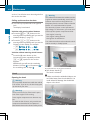
Introduction
Vehicle equipment
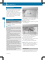
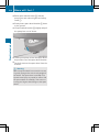
i This manual describes all the standard
and optional equipment of your vehicle
which was available at the time of
purchase. Country-specific differences are
possible. Bear in mind that your vehicle
may not feature all functions described
here. This also refers to safety-related
systems and functions.
Environmental protection
% Environmental note
Our declared policy is one of comprehensive
environmental protection.
Our objective is to use natural resources,
which are the basis of our existence on this
planet, sparingly and in a manner that takes
the requirements of both nature and
humanity into account.
You too can contribute to environmental
protection by operating your vehicle in an
environmentally responsible manner.
Fuel consumption and engine, transmission,
brake and tire wear depend on these two
factors:
Roperating
conditions of your vehicle
personal driving style
You can influence both factors.
Observe the following notes: Operating
conditions:
Ryour
Ravoid
driving short distances as this
increases fuel consumption.
Rmake sure that the tire pressures are
always correct.
Rdo not carry any unnecessary weight in/on
the vehicle.
Rkeep an eye on the vehicle's fuel
consumption.
Rremove roof racks once you no longer need
them.
Ra
regularly serviced vehicle will contribute
to environmental protection. You should
therefore adhere to the specified service
intervals.
Ralways have maintenance work carried out
at an authorized Sprinter Dealer.
Personal driving style:
Rdo not depress the accelerator pedal when
starting the engine.
not warm up the engine when the
vehicle is stationary.
Radopt an anticipatory style of driving and
keep a sufficient distance from other
vehicles.
Ravoid frequent, sudden acceleration.
Rswitch off the engine in stationary traffic.
Rdo
Environmental concerns and
recommendations
In this manual, whenever you see instructions
to discard materials, you should first attempt
to reclaim and recycle them. To preserve our
environment, follow appropriate
environmental rules and regulations when
disposing of materials.
Operating safety
Safety notes
G Warning
Engine exhaust, some of its constituents, and
certain vehicle components contain or emit
chemicals known to the State of California to
cause cancer and birth defects or other
reproductive harm.
In addition, certain fluids contained in
vehicles, and certain products of component
wear contain chemicals known to the State of
California to cause cancer and birth defects
or other reproductive harm.
Emergency tensioning retractors, airbags and
remote control batteries contain perchlorate,
which may require special handling and
Introduction
regard for the environment. Check with your
local government's disposal guidelines.
California residents: see
http: / / www.dtsc.ca.gov /
HazardousWaste / Perchlorate / index.cfm.
G Warning
If work on electronic equipment and its
software is carried out incorrectly, this
equipment could stop working. The electronic
systems are networked via interfaces.
Tampering with these electronic systems
could cause malfunctions in systems which
have not been modified. Malfunctions such as
these can seriously jeopardize the vehicle's
operating safety and therefore your own
safety.
You should therefore have all work and
modifications to electronic components
carried out at a qualified specialist workshop.
G Warning
A heavy impact to the underbody, tires or
wheels, for example when bottoming out on
rough terrain or driving over an obstacle at
high speed, could damage your vehicle. This
also applies to vehicles equipped with
underbody protection.
In this case, have your vehicle checked at an
authorized Sprinter Dealer. In particular, work
relevant to safety or on safety-related
systems must be carried out at an authorized
Sprinter Dealer.
Service and warranty information
The Service and Warranty Information
Booklet contains detailed information about
the warranties covering your Sprinter,
including
RNew
Vehicle Limited Warranty
Engine Limited Warranty
RCorrosion Warranty
RRestraint System Limited Warranty
(vehicles sold and registered in the State of
Kansas only)
REmission Warranties required by law.
RDiesel
Registering your vehicle
We may instruct our authorized Sprinter
Dealer to carry out technical inspections on
certain vehicles to improve their quality or
safety.
If you did not purchase your vehicle from an
authorized dealership and your vehicle has
not yet been inspected at an authorized
Sprinter Dealer, there is a possibility that your
vehicle has not been registered in your name.
We will only be able to inform you about
vehicle inspections if we are in possession of
your registration data.
It is advisable to have your vehicle registered
at an authorized Sprinter Dealer.
Inform us as soon as possible if your address
has changed or if there has been a change of
vehicle owner.
G Warning
Always have maintenance work carried out at
an authorized Sprinter Dealer which has the
necessary specialist knowledge and tools to
carry out the work required. In particular,
work relevant to safety or on safety-related
systems must be carried out at an authorized
Sprinter Dealer.
Digital speedometer and total
distance recorder
Do not allow the electronically stored total
distance covered by your vehicle to be
modified as a result of tampering with the
electronics system.
This type of modification or failing to inform
the buyer when selling the vehicle could
constitute an offense punishable by law.
Z
17
18
Introduction
Modifying the engine power output
Having the engine power output of your
vehicle increased by tampering with the
electronic engine management system will
invalidate the vehicle's general operating
permit and insurance coverage, as well as
your New Vehicle Limited Warranty and
warranty entitlement.
Modifications to the output of the engine
must be reported to the insurance provider
and require the vehicle to be recertified. The
tires, chassis, brake and cooling systems
must be adapted to the increased engine
power output.
Tampering with the electronic engine
management system modifies emission
values and it will not be possible to guarantee
the operating safety of the engine in every
case. Increases in performance may lead to
malfunctions and consequential damage to
other assemblies.
If you sell the vehicle, failing to inform the
buyer of the modified engine power output
could constitute an offense punishable by
law, depending on the country concerned.
accessories that have been expressly
approved for your vehicle model.
These parts have been subjected to special
tests in order to determine their safety,
reliability and suitability.
! For safety reasons, have add-on
equipment prepared and installed
according to the Sprinter body/equipment
mounting directives in force. These body/
equipment mounting directives guarantee
that the chassis and add-on equipment
form a cohesive whole and that the highest
possible level of operating and driving
safety is reached.
We recommend for safety reasons that:
Ryou
carry out no other modifications to
the vehicle.
Ryou obtain the agreement of the
distributor named on the inside of the
front cover for any deviations from the
approved body/equipment mounting
directives.
Approval by official testing centers or
permission given by authorities do not
eliminate safety risks.
! The wooden or plastic cargo area floor
Diesel particle filter
! If the vehicle is predominantly used for
short-distance driving, this could lead to a
malfunction in the automatic cleaning
function for the diesel particle filter. As a
result, fuel may accumulate in the engine
oil and cause engine failure.
Therefore, if you mainly drive short
distances, you should drive on a highway or
on rural roads for 20 minutes every
310 miles (500 km). This ensures sufficient
regeneration of the diesel particle filter.
Vehicle alterations
We recommend the use of genuine Sprinter
parts and conversion parts as well as
fitted at the factory is an integral
component of the vehicle structure. The
vehicle body could be damaged if you have
the load area floor removed. This then
affects the securing of loads and the
maximum loading capacity of the lashing
points is no longer guaranteed.
Therefore, do not have the load area floor
removed.
Even seemingly small changes to the vehicle,
such as attaching a radiator cover for winter
driving or as protection against insects, are
not allowed. These could cause the engine
diagnostics to register incorrect data. The
recording of engine diagnostic data is a legal
requirement, and must always be verifiable
and accurate.
Introduction
Sprinter body builder guideline
If you intend on making any alterations to the
vehicle, we strongly recommend that you
contact the distributor named on the inside
of the front cover in order to obtain all
necessary information (there may be a
charge).
Body builders and dealers who make any
modifications which may affect the final
certification of the engine, vehicle or
equipment assume the sole responsibility for
the vehicle, including labeling and
documentation, affected by their
modifications.
It is their responsibility to certify that the
altered vehicle conforms to all applicable
standards and regulations affected by the
vehicle alteration or continues to comply with
the motor vehicle safety standards and
emissions regulations.
They are responsible for ensuring that
modifications or equipment installation do
not affect the safety of the vehicle.
G Warning
Any modifications or alterations of the
Sprinter not in compliance with the Sprinter
Body Builder Guideline and the Sprinter
Operator's Manual may seriously inhibit its
roadworthiness and safety and may lead to an
accident resulting in serious injury or death.
Consult the Sprinter Body Builder Guideline
and the Sprinter Operator's Manual prior to
initiating any alterations or modifications.
We are not responsible for any final
certification or claims regarding product
liability, or warranty claims, which result from
any component, assembly, or system being
altered, or which cause non-compliance with
any of the emission control standards or
motor vehicle safety standards, or which
would otherwise cause the vehicle to be or to
become defective or unsafe.
We do not assume responsibility as the finalstage manufacturer or the consequential
product liability.
Correct use
Observe the following information when using
your vehicle:
Rthe
safety notes in this manual
"Technical data" section in this manual
Rtraffic rules and regulations
Rmotor vehicle laws and safety standards
Rthe
Substances constituting a health
hazard
Do not store or transport in the cab any
substances that constitute a health hazard or
react aggressively.
These include:
Rsolvents
Rfuels
Roils
and greases
agents
Racids
Rcleaning
G Warning
Do not store or transport in the cab any
substances that constitute a health hazard or
react aggressively. Gases and liquids may
escape from containers that are completely
sealed.
The driver's ability to concentrate while the
vehicle is in motion and the driver's health
could be affected. In addition, electrical
components (e. g. control units and
connectors) could be damaged. This can
result in malfunctions, system failures, or
short circuits which can start a fire.
You could cause an accident, thereby
endangering yourself and others.
Stickers and warning labels
G Warning!
Various warning labels are attached to your
vehicle. These warning labels are intended to
make you and others aware of various risks.
Do not remove any of these warning labels
Z
19
20
Introduction
unless explicitly instructed to do so by
information on the label itself.
Removing warning labels may cause you and
others to be unaware of certain risks which
may result in an accident and/or personal
injury.
Problems with your vehicle
If you should experience a problem with your
vehicle, particularly one that you believe may
affect its safe operation, we urge you to
immediately contact an authorized Sprinter
Dealer to have the problem diagnosed and
corrected if required.
If the matter is not handled to your
satisfaction, please discuss the problem with
the Sprinter Dealer management, or if
necessary contact the distributor named on
the inside of the front cover.
Reporting safety defects
In the USA:
In all 50 states and Washington, D.C.:
If you believe that your vehicle has a defect,
which could cause a crash or cause injury or
death, you should immediately inform the
National Highway Traffic Safety
Administration (NHTSA) in addition to
notifying the distributor.
If NHTSA receives similar complaints, it may
open an investigation, and if it finds that a
safety defect exists in a group of vehicles, it
may order a recall and remedy campaign.
However, NHTSA cannot become involved in
individual problems between you, your dealer
and the vehicle distributor.
To contact NHTSA, you may either call the
Auto Safety Hotline toll free at 1–888–327–
4236 (TTY: 1-800-424-9153),
or go to http: / / www.safercar.gov
or write to:
Administrator, NHTSA, 400 Seventh Street,
SW., Washington, DC 20590.
In Canada:
If you believe that your vehicle has a safety
defect, you should contact immediately the
Customer Service Department of the
distributor named on the inside of the front
cover.
Information regarding electronic
recording devices
(Including notice pursuant to California Code
§ 9951)
Please note that your vehicle is equipped with
devices that can record vehicle system data.
This information helps, for example, to
diagnose vehicle systems after a collision and
to continuously improve vehicle safety. We
may access the information and share it with
others:
Rfor
safety research or vehicle diagnosis
purposes
Rwith the consent of the vehicle owner or
lessee
Rin response to an official request by a law
enforcement or other government agency
Rfor use in dispute resolution involving
Daimler, its affiliates or sales / service
organization and / or
Ras otherwise required or permitted by law
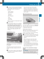
Cockpit .................................................
Instrument cluster variants ...............
Steering wheel with buttons ..............
Center console ....................................
Switch units .........................................
22
24
26
26
27
At a glance
21
22
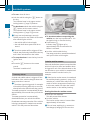
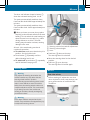
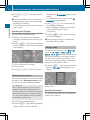
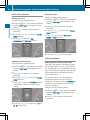
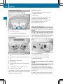
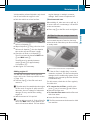
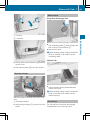
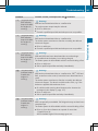
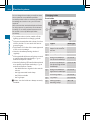
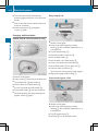
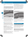
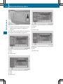
Cockpit
At a glance
Cockpit
Cockpit
i This Operator's Manual describes all the
standard and optional equipment available
for your vehicle at the time of purchase.
Country specific differences are possible.
Please note that your vehicle might not be
equipped with all the functions described
here. This also includes safety relevant
systems and functions.
Function
Function
Page
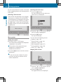
C
Instrument cluster
D
Stowage compartment
E
• Stowage compartment
with interior light
• Overhead control panel
92
27
69
Page
F
Rear-view mirror
24
:
Door control panel
28
G
Rear-view camera monitor
122
;
Light switch
89
H
=
Combination switch:
• turn signals
• high-beam headlamps
• windshield wipers
• rear window wiper
PARKTRONIC warning
display
119
?
Cruise control lever
A
Horn
B
Steering wheel without/
with buttons
90
90
94
94
118
26
Opens/closes the righthand side window
60
J
Jack and vehicle tool kit
182
K
Glove box
131
L
Center console
26
M
Ignition lock
56
N
Additional switch unit
28
I
Cockpit
Page
O
Steering wheel adjustment
P
Selector lever (automatic
transmission)
109
Parking brake
112
Q
69
Function
R
Opens the hood
S
Additional switch unit
Page
168
28
At a glance
Function
23
24
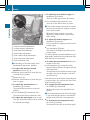
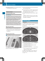
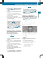
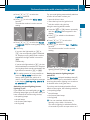
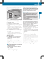
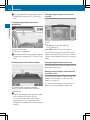
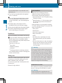
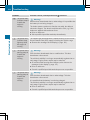
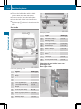
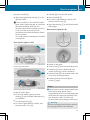
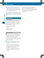
Instrument cluster variants
At a glance
Instrument cluster variants
Function
:
Instrument cluster on
vehicles without
steering-wheel buttons
Page
F
70
;
Indicator and warning
lamps
=
f, g Brightens/dims the
instrument cluster lighting
72
Tachometer with indicator
and warning lamps
71
A
Display
73
B
Fuel gauge with fuel filler
flap location indicator
72
?
71
D
Reset button 9
70
E
4 Menu button:
• changes standard display
• selects menus
70
Indicator and warning
lamps
H
Display
74
I
Tachometer with indicator
and warning lamps
71
Fuel gauge with fuel filler
flap location indicator
72
f, g Brightens/dims the
instrument cluster lighting
72
Speedometer with
indicator and warning
lamps
71
M
Reset button 9
70
N
Ë Service button
Checks the engine oil level
J
L
73
73
Instrument cluster on
vehicles with steeringwheel buttons
Page
G
K
Speedometer with
indicator and warning
lamps
C
Function
Indicator and warning
lamps
171
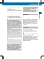
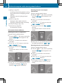
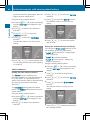
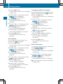
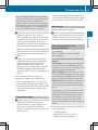
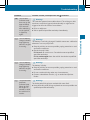
Instrument cluster variants
d ESP® warning lamp
ASR warning lamp
% Coolant level too low
Page
Function
Page
50,
187
48,
187
å DEF supply low or
contaminated/thinned
Exhaust gas aftertreatment
malfunction
193
È Dirt accumulation in air
filter
195
199
200
? Coolant temperature too
high
193
+ Restraint systems
malfunction
6 Reserve fuel
Fuel filler cap open
193
194
191
: Water in the fuel
196
b Brake fluid level too low
EBD malfunction
Trailer brake force booster
malfunction
188
187
# Battery charging
malfunction
191
b Bulb defective
197
4 Engine oil level warning
192
c Parking brake applied
112
; Engine diagnostics
indicator lamp
Exhaust gas aftertreatment
malfunction
% Preglow system
G Left-hand turn signal
h Tire pressure loss or the tire
pressure monitor is
malfunctioning (USA only)
Tire pressure loss (Canada
only)
188
L Low-beam headlamps on
89
K Working speed governor
(ADR) on
117
195
K High-beam headlamps on
90
194
| Reserve fuel
Fuel filler cap open
193
194
7 Fasten seat belt
196
194
90
195
i Vehicles with steering-wheel buttons:
195
Corresponding messages may also be
shown in display H(Y page 24).
¦ Fluid level too low in
windshield washer/
headlamp cleaning system
196
1 Door open
197
# Brake pads/linings worn
191
J Right-hand turn signal
90
! ABS malfunction
189
: ASR malfunction
BAS malfunction
189
189
h ESP® malfunction
187
At a glance
Function
25
26
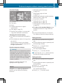
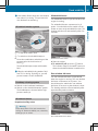
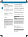
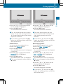
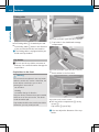
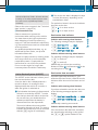
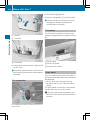
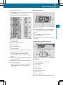
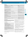
Center console
Center console
At a glance
Steering wheel with buttons
Function
:
Display
Page
74
Controls the on-board
computer
;
=
?
A
Selects a submenu or
adjusts the volume
W Up/increases the
volume
X Down/reduces the
volume
Using the telephone
6 Accepts a call/starts
dialing
~ Ends a call/rejects an
incoming call
Scrolling from one menu to
another
V Forwards
U Back
Scrolling from one
submenu to another
& Forwards
* Back
Function
74
86
74
74
Page
:
Stowage compartment
130
;
Radio; see the separate
operating instructions
=
Air-conditioning control
panel
97
?
Center console switch unit
27
A
• Stowage compartment or
• CD changer; see the
separate operating
instructions
B
Cup holder with
• ashtray
• cigarette lighter
132
128
129
C
12 V socket
133
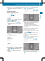
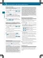
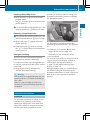
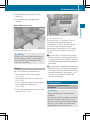
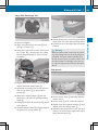
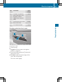
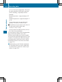
Switch units
Switch units
Roof
At a glance
Center console
Function
Function
27
Page
:
c Switches the left/righthand seat heating on/off
68
;
z Switches the windshield
heating on/off
95
=
| Switches the rear window
defroster on/off
95
?
f Activates/deactivates
PARKTRONIC
122
£ Switches the hazard
warning lamps on/off
91
à Activates/deactivates ASR
48
à Central locking, interior/
Ä rear compartment
54
A
B
Microphone for the
telephone
Page
134
Switches the right-hand
reading lamp on/off
92
Switches the automatic
interior lighting on/off
92
• Eyeglasses compartment
or
• Anti-theft alarm system
(ATA)
131
61
Switches the interior
lighting on/off
92
Switches the left-hand
reading lamp on/off
92
28
Switch units
Additional switch units
At a glance
Driver's door
Function
Page
:
Adjusts the exterior mirrors
70
;
Selects an exterior mirror
70
=
Opens/closes the left-hand
side window
?
Opens/closes the righthand side window
61
61
Switch unit between the light switch and the
steering wheel
Function
Page
y Switches the auxiliary
heating on/off
104
± Switches the heater
booster function on/off
104
E Sets the working speed
F
117
E Switches the working
speed governor (ADR) on/
off
117
´ Ventilates the cargo
· compartment
108
29
At a glance
Switch units
Switch unit between the steering wheel and
ignition lock
Function
l Switches the reark compartment convenience
lighting on/off
Page
92
30
31
32
32
45
47
Safety
Vehicle equipment ..............................
Occupant safety ..................................
Emergency exit ...................................
Driving safety systems .......................
32
Occupant safety
Vehicle equipment
Safety
i This manual describes all the standard
and optional equipment of your vehicle
which was available at the time of
purchase. Country-specific differences are
possible. Bear in mind that your vehicle
may not feature all functions described
here. This also refers to safety-related
systems and functions.
Occupant safety
Restraint systems
In this section you will learn the most
important facts about the restraint system
components of the vehicle.
The restraint systems are:
RSeat
belts
restraint systems
RLATCH-type (ISOFIX) child seat securing
system
Additional protection potential is provided by
SRS (Supplemental Restraint System) and
the air bag system.
The protective functions of the systems work
in conjunction with each other. The systems
are, however, autonomous.
RChild
G Warning
Modifications to or work improperly
conducted on restraint system components
or their wiring, as well as tampering with
interconnected electronic systems, can lead
to the restraint systems no longer functioning
as intended.
Air bags or Emergency Tensioning Devices
(ETDs), for example, could deploy
inadvertently or fail to deploy in accidents
although the deceleration threshold for air
bag deployment is exceeded. Therefore,
never modify the restraint systems. Do not
tamper with electronic components or their
software.
i More information on the subject of
children in the vehicle and child restraint
systems can be found in the "Children in
the vehicle" section (Y page 41).
Seat belts
Important safety notes
The use of seat belts and infant or child
restraints is required by law in all 50 states,
the District of Columbia, the U.S. territories
and all Canadian provinces.
Even if this is not the case, all vehicle
occupants should have their seat belts
fastened when the vehicle is in motion.
i See "Children in the vehicle"
(Y page 41) for further information on
infants and children traveling in the vehicle
as well as on child restraint systems.
G Warning!
Always fasten your seat belt before driving off.
Always make sure all of your passengers are
properly restrained. You and your passengers
should always wear seat belts.
Failure to wear and properly fasten and
position your seat belt greatly increases your
risk of injuries and their likely severity in an
accident.
If you are ever in an accident, your injuries can
be considerably more severe without your
seat belt properly buckled. Without your seat
belt buckled, you are much more likely to hit
the interior of the vehicle or be ejected from
it. You can be seriously injured or killed.
In the same crash, the possibility of injury or
death is lessened if you are properly wearing
your seat belt. The air bags can only protect
as intended if the occupants are properly
wearing their seat belts.
G Warning
Never ride in a moving vehicle with the seat
backrest in an excessively reclined position as
this can be dangerous. You could slide under
the seat belt in a collision. If you slide under
it, the seat belt would apply force at the
abdomen or neck. That could cause serious
or even fatal injuries. The seat backrest and
seat belt provide the best restraint when the
wearer is in a position that is as upright as
possible and the seat belt is properly
positioned on the body.
G Warning
Never let more people ride in the vehicle than
there are seat belts available. Make sure
everyone riding in the vehicle is correctly
restrained with a separate seat belt. Never
use a seat belt for more than one person at a
time.
G Warning
Damaged seat belts or seat belts that have
been subjected to stress in an accident must
be replaced and their anchoring points must
also be checked.
Only use seat belts which have been approved
by the distributor named on the inside of the
front cover.
Do not make any modifications to the seat
belts. This can lead to unintended activation
of the ETDs or to their failure to activate when
necessary.
Do not bleach or dye seat belts as this may
severely weaken them. In a crash they may
not be able to provide adequate protection.
Have all work carried out only by qualified
technicians. Contact an authorized Sprinter
Dealer.
Proper use of the seat belts
G Warning
USE SEAT BELTS PROPERLY
RSeat
belts can only protect when used
properly. Never wear seat belts in any other
way than as described in this section, as
that could result in serious injuries in case
of an accident.
REach occupant should wear their seat belt
at all times, because seat belts help reduce
the likelihood of and potential severity of
injuries in accidents, including rollovers.
The integrated restraint system includes
SRS (driver's front air bag, front-passenger
front air bag, side impact air bags, window
curtain air bags for door windows),
Emergency Tensioning Devices, seat belt
force limiters, and front seat knee bolsters.
The system is designed to enhance the
protection offered to properly belted
occupants in certain frontal (front air bags
and ETDs) and side (side impact air bags,
window curtain air bags, and ETDs) impacts
which exceed preset deployment
thresholds and in certain rollovers (window
curtain air bags and ETDs).
RNever wear the shoulder belt under your
arm, across your neck or not routed across
your shoulder. In a frontal crash, your body
would move too far forward. That would
increase the chance of head and neck
injuries. The seat belt would also apply too
much force to the ribs or abdomen, which
could severely injure internal organs such
as your liver or spleen.
Adjust the seat belt so that the shoulder
section is located as close as possible to
the middle of the shoulder. It should not
touch the neck. Never pass the shoulder
portion of the seat belt under your arm. For
this purpose, you can adjust the height of
the seat belt outlet.
RPosition the lap belt as low as possible on
your hips and not across the abdomen. If
the lap belt is positioned across your
abdomen, it could cause serious injuries in
a crash.
RNever wear seat belts over rigid or
breakable objects in or on your clothing,
such as eyeglasses, pens, keys etc., as
these might cause injuries.
Z
33
Safety
Occupant safety
34
Occupant safety
Safety
RMake
sure the seat belt is always routed
snugly. Take special care of this when
wearing loose clothing.
RNever use a seat belt for more than one
person at a time. Do not fasten a seat belt
around a person and another person or
other objects at the same time.
RSeat belts should not be worn twisted. In a
crash, you would not have the full width of
the seat belt to distribute impact forces.
The twisted seat belt against your body
could cause injuries.
RPregnant women should also always use a
lap-shoulder belt. The lap belt portion
should be positioned as low as possible on
the hips to avoid any possible pressure on
the abdomen.
RPlace the seat backrest in a position that is
as upright as possible.
RCheck your seat belt during travel to make
sure it is properly positioned.
RNever place your feet on the instrument
panel, dashboard, or on the seat. Always
keep both feet on the floor in front of the
seat.
RWhen using a seat belt to secure infant
restraints, toddler restraints, or children in
booster seats, always follow the child seat
manufacturer's instructions.
seats than on the front-passenger seat. Thus,
we strongly recommend that children be
placed in the rear seat whenever possible.
Regardless of seating position, children 12
years old and under must be seated and
properly secured in an appropriately sized
child restraint system or booster seat
recommended for the size and weight of the
child. For additional information, see the
"Children in the vehicle" section.
A child's risk of serious or fatal injuries is
significantly increased if the child restraints
are not properly secured in the vehicle and/
or the child is not properly secured in the child
restraint.
X
Adjust the seat and move the backrest to
an almost vertical position (Y page 63).
G Warning
Do not pass seat belts over sharp edges. They
could tear.
Do not allow the seat belt to get caught in the
door or in the seat adjustment mechanism.
This could damage the seat belt.
Never attempt to make modifications to seat
belts. This could impair the effectiveness of
the seat belts.
Fastening seat belts
G Warning
According to accident statistics, children are
safer when properly restrained on the rear
X
Pull the seat belt smoothly through belt
sash guide :.
X Without twisting it, place the shoulder
section of the seat belt over the center of
the shoulder and the lap section across the
hips.
X Engage belt tongue ; in buckle ?.
Occupant safety
X
If necessary, adjust the seat belt to the
appropriate height (Y page 35).
X If necessary, pull upwards on the shoulder
section of the seat belt to tighten the belt
across your body.
Slide belt sash guide : downwards.
X Release belt sash guide release A and
make sure that belt sash guide : has
engaged.
All seat belts in the vehicle, except the
driver's seat belt, are equipped with a special
seat belt retractor to secure child restraint
systems properly. For further information on
"Special seat belt retractors", see
(Y page 43).
For more information about releasing the seat
belt with release button ?, see "Releasing
seat belts" (Y page 35).
Releasing seat belts
X Press release button = and guide belt
tongue ; back towards belt sash
guide :.
Adjusting the seat belt height
You can adjust the seat belt height on the
driver's seat and the outer co-driver's seat.
Adjust the belt to a height that allows the
upper part of the seat belt to be routed across
the center of your shoulder.
Safety
X
! Make sure that the seat belt retracts fully.
The seat belt or belt buckle may otherwise
become trapped in the door or the seat
adjustment mechanism. This could
damage the door, door trim panels and the
seat belt. Damaged seat belts can no
longer provide the intended degree of
protection and must be replaced. Contact
an authorized Sprinter Dealer.
Belt warning for drivers and co-drivers
Regardless of whether the driver's and codriver's seat belts have already been
fastened, the 7 seat belt warning lamp
lights up for six seconds each time the engine
is started. It then goes out once the driver and
the front passenger have fastened their seat
belts.
If the driver's seat belt is not fastened after
the engine is started, an additional warning
tone will sound. The warning tone goes out
after approximately six seconds or once the
driver's seat belt is fastened.
Emergency Tensioning Devices, seat
belt force limiters
X
To raise: slide belt sash guide : upwards.
The belt sash guide engages in various
positions.
X To lower: press and hold belt sash guide
release A.
35
If the vehicle is equipped with a driver's front
air bag, the seat belts on the driver's and codriver's seats have ETDs.
! If the front-passenger seat is not
occupied, do not engage the seat belt
tongue in the buckle on the frontpassenger seat. Otherwise, the Emergency
Tensioning Device could be triggered in the
event of an accident.
Z
Safety
36
Occupant safety
ETDs help remove slack in the seat belts in an
accident, pulling the seat belt close against
the occupant's body.
ETDs do not correct incorrect seat positions
or incorrectly fastened seat belts.
ETDs do not pull vehicle occupants back
towards the backrest.
If the seat belt is also equipped with a seat
belt force limiter and this is triggered, the
force exerted by the seat belt on the vehicle
occupant is reduced.
The seat belt force limiters are synchronized
with the front air bags, which take on a part
of the deceleration force in an accident. Thus,
the force exerted on the occupant is
distributed over a greater area.
The ETDs can only be triggered if the ignition
is switched on and the restraint systems are
operational, see "SRS warning lamp" .
The ETDs are triggered depending on the type
and severity of an accident:
Rin
the event of a head-on or rear-end
collision, if the vehicle decelerates or
accelerates rapidly in a longitudinal
direction during the initial stages of the
impact
Rin the event of a side impact if the vehicle
decelerates or accelerates rapidly in a
lateral direction and the vehicle is equipped
with side impact air bags and/or window
curtain air bags
Rin certain situations, if the system detects
that the vehicle will overturn
If the ETDs are triggered, you will hear a bang
and powder may also be released. In rare
cases the bang may temporarily affect your
hearing. The power emitted is generally not
hazardous to health. The + SRS indicator
lamp lights up.
G Warning
Pyrotechnic ETDs that were activated must be
replaced.
For your safety, when disposing of the
pyrotechnic ETDs always follow our safety
instructions. These are available at any
authorized Sprinter Dealer.
SRS (Supplemental Restraint System)
Introduction
SRS reduces the risk of occupants hitting the
vehicle interior in the event of an accident. In
addition, it can reduce the forces the
occupants are subjected to during an
accident.
SRS consists of:
Rthe
+ SRS indicator lamp
bags
Rair bag control unit (with crash sensors)
RETDs for the driver's and co-driver's seat
Rseat belt force limiters, for the driver's and
co-driver's seat
Rair
+ indicator lamp
The SRS system conducts a self-test when
the ignition is switched on and in regular
intervals while the engine is running. This
facilitates detection of system malfunctions.
The + SRS indicator lamp in the
instrument cluster comes on when the
ignition is switched on.
It goes out no later than a few seconds after
the engine has been started.
The SRS components are in operational
readiness when the + SRS indicator lamp
is not lit while the engine is running.
G Warning
The SRS self-check has detected a
malfunction if the + SRS indicator lamp:
Rdoes
not come on at all
to go out approximately 4 seconds
after the engine was started
Rcomes on after the engine was started or
while driving
For your safety, we strongly recommend
having the system checked by an authorized
Rfails
Occupant safety
Safety guidelines for the seat belts, the
Emergency Tensioning Devices and the
air bags
G Warning
RDamaged seat belts or seat belts that have
been subjected to stress in an accident
must be replaced and their anchoring
points must also be checked. Only use seat
belts which have been installed or supplied
by an authorized Sprinter Dealer.
RAir bags and pyrotechnic Emergency
Tensioning Devices (ETDs) contain
perchlorate material, which may require
special handling and regard for the
environment. Check with your local
government’s disposal guidelines.
California residents, see
www.dtsc.ca.gov/HazardousWaste/
Perchlorate/index.cfm.
RAir bags and ETDs are designed to function
on a one-time-only basis. An air bag or ETD
that has deployed must be replaced.
RDo not pass seat belts over sharp edges.
They could tear.
RDo
not make any modification that could
change the effectiveness of the seat belts.
RDo not bleach or dye seat belts as this may
severely weaken them. In a crash they may
not be able to provide adequate protection.
RNo modifications of any kind may be made
to any components or wiring of the SRS.
RDo not change or remove any component
or part of the SRS.
RDo not install additional paneling, seat
covers, badges etc. over the steering wheel
hub, co-driver's front air bag cover,
outboard sides of the seat backrests, door
trim panels, or door frame trims.
RDo not install additional electrical/
electronic equipment on or near SRS
components and wiring.
RKeep the area between air bags and
occupants free of objects (e.g. packages,
purses, umbrellas etc.).
RDo not hang items such as coat hangers
from the coat hooks or handles over the
door. These items may be thrown around in
the vehicle and cause head and other
injuries when the window curtain air bag is
deployed.
RAir bag system components will be hot after
an air bag has inflated. Do not touch them.
RNever place your feet on the instrument
panel or on the seat. Always keep both feet
on the floor in front of the seat.
RImproper repair work creates a risk of
rendering the SRS inoperative or causing
unintended air bag deployment. Work on
the SRS must therefore only be performed
by qualified technicians. Contact an
authorized Sprinter Dealer.
RFor your protection and the protection of
others, when scrapping the air bag unit or
ETD, our safety instructions must be
followed. These instructions are available
from any authorized Sprinter Dealer.
RGiven the considerable deployment speed,
required inflation volume, and the material
of the air bags, there is the possibility of
Z
Safety
Sprinter Dealer immediately. Otherwise SRS
may not be activated when it is needed in an
accident, which could result in serious or fatal
injury. SRS might also deploy unexpectedly
and unnecessarily which could also result in
injury.
In addition, improper work on SRS creates a
risk of rendering SRS inoperative or causing
unintended air bag deployment. Work on SRS
must therefore be performed by qualified
technicians. Contact an authorized Sprinter
Dealer.
If it is necessary to modify an air bag system
to accommodate a person with disabilities,
contact an authorized Sprinter Dealer for
details.
USA only: for detailed information, please
consult our Customer Assistance Center at
1-877-762-8267.
37
38
Occupant safety
Safety
abrasions or other, potentially more serious
injuries resulting from air bag deployment.
If you sell your vehicle, we strongly
recommend that you inform the subsequent
owner that the vehicle is equipped with SRS.
Also refer them to the applicable section in
the Operator's Manual.
Air bags
Important safety notes
G Warning
Air bags are designed to reduce the incidence
of injuries and fatalities in certain situations:
Rfrontal
impacts (driver's and frontpassenger front air bags)
Rside impacts (side impact air bags and
window curtain air bags)
Rrollover (window curtain air bags)
However, no system available today can
completely eliminate injuries and fatalities.
When the air bags are deployed, a small
amount of powder is released. The powder
generally does not constitute a health hazard
and does not indicate that there is a fire in the
vehicle. In order to prevent potential
breathing difficulties, you should leave the
vehicle as soon as it is safe to do so. If you
have any breathing difficulty but cannot get
out of the vehicle after the airbag inflates,
then get fresh air by opening a window or
door.
G Warning
To reduce the risk of injury when the front air
bags inflate, it is very important for the driver
and co-driver to always be in a properly seated
position and to wear their respective seat
belt.
For maximum protection in the event of a
collision always be in normal seated position
with your back against the seat backrest.
Fasten your seat belt and make sure it is
properly positioned on your body.
Since the air bag inflates with considerable
speed and force, a proper seating position
and correct positioning of the hands on the
steering wheel will help to keep you at a safe
distance from the air bag. Occupants who are
not wearing their seat belt, are not seated
properly or are too close to the air bag can be
seriously injured or killed by an air bag as it
inflates with great force instantaneously:
RSit with the seat belt properly fastened in a
position that is as upright as possible with
your back against the seat backrest.
RMove the driver’s seat as far back as
possible, still permitting proper operation
of vehicle controls. The distance from the
center of the driver’s chest to the center of
the air bag cover on the steering wheel
must be at least 10 inches (25 cm) or more.
You should be able to accomplish this by
adjusting the seat and steering wheel. If
you have any difficulties, please contact an
authorized Sprinter Dealer.
RDo not lean your head or chest close to the
steering wheel or instrument panel.
RKeep hands on the outside of the steering
wheel rim. Placing hands and arms inside
the rim can increase the risk and potential
severity of hand/arm injury when the driver
front air bag inflates.
RMove the co-driver's seat as far as possible
away from the instrument panel when the
seat is occupied.
ROccupants, especially children, should
never place their bodies or lean their heads
in the area of the door where the side
impact air bag inflates. This could result in
serious injuries or death should the side
impact air bag be deployed. Always sit as
upright as possible, wear the seat belt
properly and use an appropriately sized
infant restraint, toddler restraint, or
booster seat recommended for the size and
weight of the child.
RChildren twelve years old and under must
never travel on the co-driver's seat. They
will otherwise be struck by the co-driver's
front air bag when it inflates in a crash. This
could result in serious or fatal injury.
Failure to follow these instructions can result
in severe injuries to you or other occupants.
If you sell your vehicle, it is important that you
make the buyer aware of this safety
information. Be sure to give the buyer this
Operator’s Manual.
G Warning
Accident research shows that the safest place
for children in an automobile is in a rear seat.
A side impact air bag related injury may occur
if occupants, especially children, are not
properly seated or restrained when next to a
side impact air bag which needs to deploy
rapidly in a side impact in order to do its job.
To help avoid the possibility of injury, please
follow these guidelines:
(1)
(2)
(3)
Occupants, especially children,
should never place their bodies or
lean their heads in the area of the
door where the side impact air bag
inflates. This could result in
serious injuries or death should
the side impact air bag be
deployed.
Always sit as upright as possible
and use the seat belts properly.
Make sure that children 12 years
old and under use an appropriately
sized child restraint, infant
restraint, or booster seat
recommended for the size and
weight of the child.
Always wear seat belts properly.
The driver and passenger should always wear
their seat belts. Otherwise, it is not possible
for the air bags to provide their supplemental
protection.
In the event of other types of impacts and
impacts below air bag deployment
thresholds, air bags will not deploy. The driver
and passengers will then be protected to the
extent possible by a properly fastened seat
belt. A properly fastened seat belt is also
needed to provide the best possible
protection in a rollover.
Air bags provide supplemental protection, but
are not a substitute for the seat belts. All
vehicle occupants must fasten their seat
belts regardless of whether your vehicle is
equipped with air bags or not.
It is important for your safety and that of your
passengers to have deployed air bags
replaced and to have any malfunctioning air
bags repaired. This will help to make sure the
air bags continue to perform their protective
function for the vehicle occupants in the
event of a crash.
Front air bags
G Warning
Observe "Important safety notes"
(Y page 38).
The front air bags increase the degree of
protection afforded to the driver and co-driver
against head and chest injuries.
The air bags are only deployed if the air bag
control unit detects the need for deployment.
Only in the event of such a situation will they
provide their supplemental protection.
Z
39
Safety
Occupant safety
40
Occupant safety
Safety
Driver's front air bag : deploys in front of
the steering wheel; co-driver's front air
bag ; deploys in front of and above the glove
box. They are deployed:
Rin
the event of certain frontal impacts
the system determines that air bag
deployment can offer additional protection
to that provided by the seat belt
Rif the respective seat belt is fastened
Rindependently of other air bags in the
vehicle
If the event of a rollover, the front air bags are
generally not deployed unless the system
detects high vehicle deceleration in a
longitudinal direction.
The air bags will not deploy in impacts which
do not exceed the system's preset
deployment thresholds. You will then be
protected by the seat belt, provided that it is
fastened.
Rif
Side impact air bags
G Warning
Observe "Important safety notes"
(Y page 38).
Improper repair work on the doors or the
modification or addition of components to the
doors creates a risk of rendering the side
impact air bags inoperative or causing
unintended air bag deployment. Work on the
doors must therefore only be performed by
qualified technicians. Contact an authorized
Sprinter Dealer.
G Warning
Only use seat covers which have been tested
and approved for your vehicle type by the
distributor named on the inside of the front
cover. Using other seat covers may interfere
with or prevent the deployment of the front
side impact air bags. Contact an authorized
Sprinter Dealer for availability.
When deployed, the side impact air bags offer
additional protection for the thorax of the
vehicle occupants on the side of the vehicle
on which the impact occurs. However, they
do not protect the:
Rhead
Rneck
Rarms
G Warning
If you wish to use seat covers, we recommend
for safety reasons that you use only those
approved for Sprinter vehicles.
The seat covers must feature a special tear
seam for the side impact air bags. The side
impact air bag may otherwise not deploy
correctly and may fail to provide the intended
degree of protection in the event of a collision.
Suitable seat covers can be obtained from any
authorized Sprinter Dealer.
G Warning
The pressure sensors for side impact air bag
control are located in the doors. Do not
modify any components of the doors or door
trim panels including, for example, the
addition of door speakers.
Side impact air bags : deploy next to the
outer seat cushions.
Side impact air bags : are deployed:
Ron
the side on which the impact occurs
the start of an accident with a high rate
of lateral vehicle deceleration or
acceleration, e.g. in a side impact
Rwhether or not the seat belt is fastened
Rat
Occupant safety
of the front air bags
of the Emergency
Tensioning Devices
The side impact air bags are generally not
deployed in the event of a rollover, unless the
system detects high vehicle deceleration or
acceleration in a lateral direction and
determines that they can offer additional
protection to that provided by the seat belt.
The side impact air bags are not deployed in
side impacts which do not exceed the
system's deployment threshold.
Rindependently
Window curtain air bags
G Warning
Observe "Important safety notes"
(Y page 38).
The window curtain air bags enhance
protection for the head (but not the chest or
arms) of the vehicle occupants on the side of
the vehicle on which the impact occurs.
The window curtain air bags are installed in
the side of the roof frame above the front
doors.
Window curtain air bags : are deployed:
Ron
the side on which the impact occurs
the start of an accident with a high rate
of lateral vehicle deceleration or
acceleration, e.g. in a side impact
Rregardless of whether the co-driver's seat
is occupied
Rwhether or not the seat belt is fastened
Rat
the event of a rollover where the system
determines that air bag deployment can
offer additional protection to that provided
by the seat belt
Rindependently of the front air bags
Rindependently of the Emergency
Tensioning Devices
The window curtain air bags will not deploy in
impacts which do not exceed the system's
preset thresholds. You will then be protected
by the seat belt, provided that it is fastened.
Rin
Children in the vehicle
Important safety notes
If an infant or child is traveling in the vehicle:
X
Secure the child using an infant or child
restraint system appropriate to the age and
weight of the child.
X Make sure that the infant or child is
properly secured at all times while the
vehicle is in motion.
G Warning
When leaving the vehicle, always remove the
key from the ignition lock. Always take the key
with you and lock the vehicle. Do not leave
children unattended in the vehicle, even if
they are secured in a child restraint system,
or with access to an unlocked vehicle. A
child's unsupervised access to a vehicle could
result in an accident and/or serious personal
injury.
Children could injure themselves on parts of
the vehicle or could suffer severe or fatal
injury due to extreme heat or cold.
If children open a door, they could injure other
persons or get out of the vehicle and injure
themselves or be injured by following traffic.
Do not expose the child restraint system to
direct sunlight. This could cause, for example,
metal parts of the child restraint system to
become very hot. Touching these parts could
cause burns.
Z
Safety
Rindependently
41
42
Occupant safety
Safety
G Warning
Do not carry heavy or hard objects in the
passenger compartment unless they are
firmly secured in place.
Unsecured or improperly positioned cargo
increases a child's risk of injury in the event
of:
Rstrong
braking maneuvers
changes of direction
Ran accident
Rsudden
Child restraint systems
Important safety notes
G Warning
Observe "Important safety notes"
(Y page 41).
We recommend all infants and children be
properly restrained using the child restraint
systems at all times while the vehicle is in
motion.
The use of infant or child restraints is required
by law in all 50 states, the District of
Columbia, the U.S. territories and all
Canadian provinces.
Infants and small children should always be
seated in an infant or child seat restraint
system appropriate for the size and weight of
the child. They must be properly secured in
accordance with the manufacturer's
installation instructions for the infant or child
seat restraint system. All infant and child seat
restraint systems must comply with the US
Federal Motor Vehicle Safety Standards 213
and 225 and Canadian Motor Vehicle Safety
Standards 213 and 210.2.
A statement by the child restraint
manufacturer of compliance with these
standards can be found on the instruction
label on the child restraint system. You will
also find the statement in the instruction
manual provided with the child restraint
system.
When using any infant restraint, child
restraint or booster seat, make sure to
carefully read and follow all manufacturer's
instructions for installation and use.
Please read the warning labels affixed to the
interior of the vehicle or to the infant restraint
system or child restraint system.
G Warning
Accident statistics show that children
secured in the rear seats are safer than
children secured in the co-driver's seat. For
this reason, we strongly advise that you
always secure children in the rear seats.
Regardless of the seat position, children
under 12 years must be secured correctly in
a suitable infant or child restraint system or
booster seat suitable for the size and weight
of the child.
The infant or child restraint must be properly
secured with the vehicle’s seat belt, the seat
belt and Top Tether strap, or lower anchors
and Top Tether strap, fully in accordance with
the child seat manufacturer’s instructions.
Occupants, in particular children, must sit as
upright as possible, fasten the seat belt
correctly and use a suitable infant restraint
system, child restraint system or booster seat
suitable for the size and weight of the child.
Children can be seriously or even fatally
injured by an air bag deploying. Observe the
following important information if it is
absolutely necessary to carry a child on the
co-driver's seat:
RThe
co-driver's front air bag is not
deactivated.
RNever secure your child in a rearwardfacing child restraint system on the codriver's seat. Only install a rearward-facing
child restraint system on a suitable rear
seat.
RWhere permitted by law, if you secure your
child in a forward-facing child restraint
system on the co-driver's seat, move the
co-driver's seat as far back to the rear as
possible.
Occupant safety
place anything between the seat
cushion and child seat (e.g. pillow). The
bottom of the child seat must make full
contact with the vehicle seat cushion. An
incorrectly mounted child seat could cause
injuries to the child in the event of an
accident, instead of protecting the child.
RObserve the manufacturer's instructions
when installing special child restraint
systems.
G Warning
Infants and small children should never share
a seat belt with another occupant. During an
accident, they could be crushed between the
occupant and seat belt.
A child's risk of serious or fatal injuries is
significantly increased if the child restraints
are not properly secured in the vehicle and/
or the child is not properly secured in the child
restraint.
Children too big for a toddler restraint must
ride in seats using regular seat belts. Position
the shoulder belt across the chest and
shoulder, not face or neck. A booster seat
may be necessary to achieve proper seat belt
positioning for children over 41 lb (18 kg) until
they reach a height where a lap/shoulder belt
fits properly without a booster.
When the child restraint is not in use, remove
it from the vehicle or secure it with the seat
belt to prevent the child restraint from
becoming a projectile in the event of an
accident.
Special seat belt retractor
G Warning
Observe "Important safety notes"
(Y page 41).
All seat belts in the vehicle, except the
driver's seat belt, are equipped with a special
seat belt retractor. When activated, the
special seat belt retractor ensures that the
seat belt cannot slacken once the child seat
is secured.
Installing a child restraint system:
X
Always comply with the manufacturer's
installation instructions.
X Pull the seat belt smoothly from the inertia
reel.
X Engage the seat belt tongue in the belt
buckle.
Activating the special seat belt retractor:
X
Pull the seat belt out fully and let the inertia
reel retract it again.
While the seat belt is retracting, you should
hear a ratcheting sound. The special seat
belt retractor function is enabled.
X Push down on the child restraint system to
take up any slack.
Removing a child restraint system/
deactivating the special seat belt retractor:
X
Always comply with the manufacturer's
installation instructions.
X Press the seat belt release button and
guide the belt tongue to the belt outlet.
The special seat belt retractor function is
deactivated.
G Warning
Never release the seat belt buckle while the
vehicle is in motion, since the special seat belt
retractor will be deactivated.
LATCH-type (ISOFIX) child seat securing
system in the rear compartment
G Warning
Observe "Important safety notes"
(Y page 41).
G Warning
Children too big for a toddler restraint must
ride in seats using regular seat belts. Position
the shoulder belt across the chest and
shoulder, not face or neck.
In order to attain the correct seating position
for children weighing over 41 lb (18 kg), it may
be necessary to use a booster seat until they
reach a height where a normal lap/shoulder
Z
Safety
RNever
43
Safety
44
Occupant safety
seat belt lies properly across their bodies
without the need for a booster seat.
Install the child restraint system according to
the manufacturer's instructions.
The child restraint system must be installed
firmly on both brackets.
An incorrectly installed child restraint system
can come loose in the event of an accident,
causing the child to be severely or fatally
injured.
Child restraint systems/child restraint
retaining brackets that are damaged or have
suffered damage due to an impact must be
replaced.
LATCH-type (ISOFIX) is a standardized
securing system for special child restraint
systems on the rear seats.
The securing rings for two LATCH-type
(ISOFIX) child restraint systems are located
between the seat cushions and the backrest:
Ron the left and right outer sides on a narrow
rear bench seat with three seats
the outer left side on a rear bench seat
with two seats
Install child restraint systems without the
LATCH-type (ISOFIX) securing system using
the vehicle's seat belts. Follow the
manufacturer's instructions for installation of
child restraint systems.
Ron
! When installing the child restraint system,
make sure that the seat belt for the center
seat does not get trapped. Otherwise, the
seat belt could be damaged.
: Securing rings
X
Install the LATCH-type (ISOFIX) child
restraint system. Comply with the
manufacturer's instructions when
installing the LATCH-type (ISOFIX) child
restraint system.
Top Tether
G Warning
Observe "Important safety notes"
(Y page 41).
Top Tether provides an additional attachment
point between the "LATCH" type child seat
mount (ISOFIX) child restraint system and the
rear seat. It helps reduce even further the risk
of injury.
The Top Tether anchorages are located on the
feet at the rear of the rear bench seats.
You can use the child-proof locks in the doors
to secure the sliding door and the rear door
individually.
A door with an activated child-proof lock
cannot be opened from the inside. It can only
be opened from the outside if the vehicle is
unlocked.
X
Move head restraint : upwards.
Install the "LATCH" child seat mount with
Top Tether. Comply with the
manufacturer's installation instructions
when doing so.
X Route Top Tether belt ? under head
restraint : between both head restraint
bars.
X Hook Top Tether hook = of Top Tether
belt ? into Top Tether anchorage ;.
Make sure that:
X
Tether hook = is hooked into Top
Tether anchorage ;, as illustrated.
RTop Tether belt ? is not twisted.
X Tension Top Tether belt ?. Comply with
the manufacturer's installation
instructions when doing so.
X If necessary, push the head restraint back
down slightly. Make sure that the routing of
Top Tether belt ? is not impaired.
Child-proof lock for the sliding door
RTop
Child-proof locks for the rear doors
G Warning
Observe "Important safety notes"
(Y page 41).
G Warning
Children could open a rear door from inside
the vehicle. This could result in serious
injuries or an accident. Therefore, when
children ride in the rear always secure the rear
doors with the child-proof locks.
Child-proof lock for the rear door
: Latch
; To activate
= To deactivate
X
To activate/deactivate: push latch : in
the corresponding direction.
X Then, make sure that the child-proof locks
are working properly.
Emergency exit
Emergency exit window
The vehicle may feature an emergency exit
window. The emergency exit window is
intended for use in an emergency only and
Z
45
Safety
Emergency exit
Safety
46
Emergency exit
must not be opened unless the vehicle is
stationary.
In an emergency, or after an accident, the
vehicle occupants can exit the vehicle
through the emergency exit window.
The emergency exit window is the first
window behind the driver's seat on the
driver's side. It is marked by the "Emergency
Exit" label.
G Warning
Observe the following notes to make sure that
the emergency exit window can be used
safely in the event of an emergency:
RBefore
beginning a journey, inform the
vehicle occupants of the emergency exit
window and explain how to use it. Make
sure to explicitly point out the risks
described here.
ROnly vehicle occupants who know how to
use the emergency exit window are
permitted to sit next to it.
RAccess to the emergency exit window must
remain unobstructed. Do not place any
large or heavy objects on or in front of the
seats next to the emergency exit window.
RThe window handles must not be used as
hooks, e.g. to hang up light objects, bags
or items of clothing.
G Warning
To reduce the risk of accident or injury when
exiting the vehicle through the emergency
exit window, observe the following notes:
ROnly
open the emergency exit window
when the vehicle is stationary.
RMake sure that nobody becomes trapped,
both when closing and when opening the
emergency exit window. The emergency
exit window must be held open by one
person.
RPay attention to the traffic conditions and
make sure that there is sufficient space
when exiting through the emergency exit
window.
RPay attention to the traffic conditions when
exiting the vehicle. Also pay attention to the
vehicle height and the local surroundings.
Be especially careful if there are children in
the vicinity.
G Warning
An open or unlocked emergency exit window
can be torn from its anchorages when the
vehicle is in motion and can thereby cause an
accident.
For this reason, always check the lock and the
locking pins of the emergency exit window
before driving off.
Never open the emergency exit window while
the vehicle is in motion.
! Make sure there is sufficient clearance
when opening the emergency exit window.
Hold the open window in position. You
could otherwise damage the emergency
exit window.
X
To open: turn both handles : to a vertical
position. Locking pins ; will break in the
process.
The window is unlocked.
X Swing the window outwards by the handles
and hold it in this position. Make sure there
is sufficient clearance when doing so.
X To close: close the window.
Driving safety systems
Turn both handles : to a horizontal
position. Make sure that locks = are in
front of the window frame on the inside.
The window is locked.
X Replace locking pins ; before beginning a
new journey at the latest.
You may obtain information about this from
any authorized Sprinter Dealer.
snow chains. Only in this way will the
driving safety systems described in this
section work as effectively as possible.
Overview
In this section, you will find information about
the following driving safety systems:
(Anti-lock Braking System)
(Brake Assist System)
RESP® (Electronic Stability Program)
RASR (Acceleration Skid Control)
REBD (Electronic Brake force Distribution)
RABS
Driving safety systems
Important safety notes
G Warning
The following factors increase the risk of
accidents:
RExcessive
speed, especially in turns
RWet and slippery road surfaces
RFollowing another vehicle too closely
The driving safety systems described in this
section cannot reduce these risks or prevent
the natural laws of physics from acting on the
vehicle. They cannot increase braking or
steering efficiency beyond that afforded by
the condition of the vehicle brakes and tires
or the traction afforded.
Only a safe, attentive, and skillful driver can
prevent accidents.
The capabilities of a vehicle equipped with the
driving safety systems described in this
section must never be exploited in a reckless
or dangerous manner which could jeopardize
the user's safety or the safety of others.
Always adjust your driving style to the
prevailing road and weather conditions and
keep a safe distance to other road users and
objects on the street.
If a driving system malfunctions, other driving
safety systems may also switch off. Observe
indicator and warning lamps that may come
on as well as messages in the multifunction
display that may appear.
i In wintry driving conditions, always use
winter tires (M+S tires) and if necessary,
RBAS
ABS (Anti-lock Braking System)
Important safety notes
G Warning
Observe "Important safety notes"
(Y page 47).
G Warning!
Do not pump the brake pedal. Use firm, steady
brake pedal pressure instead. Pumping the
brake pedal reduces the braking effect.
ABS regulates brake pressure in such a way
that the wheels do not lock during braking.
This allows you to maintain the ability to steer
your vehicle.
ABS works from a speed of about 3 mph
(5 km/h) upwards, regardless of road-surface
conditions. ABS works on slippery surfaces,
even when you only brake gently.
The ! warning lamp in the instrument
cluster lights up when the ignition is switched
on. It goes out when the engine is running.
Braking
If ABS intervenes when braking, you will feel
a pulsating in the brake pedal.
If the d warning lamp flashes, this may
indicate dangerous road conditions and
Z
Safety
X
47
Safety
48
Driving safety systems
serves as a reminder to take extra care while
driving.
X If ABS intervenes: continue to depress the
brake pedal with force until the braking
situation is over.
X To make a full brake application:
depress the brake pedal with full force.
G Warning
If the ABS malfunctions, other driving systems
such as the BAS or the ESP® are also switched
off. Observe indicator and warning lamps that
may come on as well as messages in the
multifunction display that may appear.
If the ABS malfunctions, the wheels may lock
during hard braking, reducing the steering
capability and extending the braking distance.
BAS (Brake Assist System)
G Warning
Observe "Important safety notes"
(Y page 47).
BAS operates in emergency braking
situations. If you depress the brake pedal
quickly, BAS automatically boosts the braking
force, potentially reducing the stopping
distance.
X Keep the brake pedal firmly depressed until
the emergency braking situation is over.
ABS prevents the wheels from locking.
The brakes will function as usual once you
release the brake pedal. BAS is deactivated.
G Warning
If the BAS malfunctions, the brake system still
functions, but without the additional brake
boost available that the BAS would normally
provide in an emergency braking maneuver.
Therefore, the braking distance may increase.
EBD (Electronic Brake force
Distribution)
G Warning
Observe "Important safety notes"
(Y page 47).
EBD monitors and controls the brake
pressure on the rear wheels to improve
driving stability while braking.
G Warning
If the h, :, ! and b indicator
lamps light up while the vehicle is in motion,
EBD may be defective.
If EBD malfunctions, the brake system will still
function with full brake boost. However, the
rear wheels could lock up during emergency
braking situations, for example. You could
lose control of the vehicle and cause an
accident.
Adapt your driving style to the changed
driving characteristics.
ASR (acceleration skid control)
Important safety notes
G Warning
Observe "Important safety notes"
(Y page 47).
ASR can significantly improve traction, i.e.
the transmission of power from the tires to
the road surface, and thus may increase the
vehicle's driving stability. ASR assists in
pulling away and accelerating, particularly on
smooth and slippery surfaces.
ASR can brake individual wheels and limits
the engine torque to help prevent the drive
wheels from spinning.
If ASR intervenes, the d warning lamp
flashes in the instrument cluster.
Driving safety systems
Never switch off ASR when you see the
d warning lamp flashing in the instrument
cluster. In this case proceed as follows:
Rwhen
driving off, apply as little throttle as
possible.
Rwhile driving, ease off the accelerator
pedal.
Radapt your speed and driving style to the
prevailing road conditions.
Failure to observe these guidelines could
cause the vehicle to skid. ESP® cannot
prevent accidents resulting from excessive
speed.
If, taking tires, cargo load and gradient into
consideration, the surface driven on still
provides insufficient traction, you may
experience difficulties in pulling away despite
ASR.
Vehicles without steering-wheel buttons:
the : indicator lamp in the instrument
cluster lights up when you switch on the
ignition. It goes out when the engine is
running.
If you deactivate ASR:
Rthe engine's torque is no longer limited and
the drive wheels can spin. The spinning of
the wheels results in a cutting action, which
provides better grip.
Rbrake intervention will continue to improve
traction where a drive wheel begins to spin,
e.g. if only the side of the road is slippery.
The wheel will be braked to increase
traction under such circumstances.
Ractive brake intervention by ESP® to
increase driving stability remains active.
G Warning
Even with ASR deactivated, ESP® remains
active and continues to perform brake
interventions where this is necessary to
improve driving stability. The d warning
lamp flashes.
With ASR deactivated, there is an increased
risk of your vehicle's brake system
overheating and suffering damage due to
prolonged application. A hot brake system will
also result in increased stopping distance.
Therefore, only deactivate ASR when
absolutely necessary.
Activating/deactivating ASR
G Warning
ASR should not be switched off during normal
driving other than in the circumstances
described below. Deactivating the system will
reduce vehicle stability in driving maneuvers.
Do not switch off ASR when a spare wheel is
mounted.
ASR is activated automatically when the
engine is running.
It may be best to deactivate ASR briefly in the
following situations:
X
Press button :.
When ASR is deactivated, the d warning
lamp in the instrument cluster lights up.
Rwhen
using snow chains
deep snow
Ron sand or gravel
Rin
Z
Safety
G Warning
49
50
Driving safety systems
ESP® (Electronic Stability Program)
Safety
G Warning
Observe "Important safety notes"
(Y page 47).
If ESP® detects that the vehicle is deviating
from the direction desired by the driver, one
or more wheels are braked to help stabilize
the vehicle. If necessary, the engine output is
also modified to help keep the vehicle on the
desired course within physical limits. ESP®
assists the driver when pulling away on wet
or slippery roads. ESP® can also help stabilize
the vehicle during braking.
If ESP® intervenes, the d warning lamp
flashes in the instrument cluster.
G Warning
If the h indicator lamp remains lit, ESP® is
not available due to a malfunction. Vehicle
stability in standard driving maneuvers is
reduced.
Adapt your speed and driving style to the
prevailing road conditions and to the nonoperating status of ESP®.
If ESP® is malfunctioning, the engine output
may be reduced.
! Only operate the vehicle for a maximum
of ten seconds on a brake test
dynamometer. Switch off the ignition.
Application of the brakes by ESP® may
otherwise destroy the brake system.
! Do not operate the vehicle on a
dynamometer (e.g. for a performance test).
If you would like to operate the vehicle on
a dynamometer, consult an authorized
Sprinter Dealer beforehand. The drive train
or brake system could otherwise be
damaged.
i Only use wheels with the recommended
tire sizes. Only then will ESP® function
properly.
Vehicle equipment .............................. 52
Opening and closing ........................... 52
Anti-theft systems .............................. 61
Seats .................................................... 63
Steering wheel .................................... 69
Mirrors ................................................. 69
Instrument cluster .............................. 70
On-board computer without steering wheel buttons ............................... 72
On-board computer with steering
wheel buttons ..................................... 74
Power supply ....................................... 87
Lighting ................................................ 88
Good visibility ...................................... 94
Climate control .................................... 97
Driving and parking .......................... 108
Brakes ................................................ 112
Automatic transmission ................... 113
Driving the vehicle ............................ 116
Driving systems ................................ 117
Features ............................................. 128
Communications ............................... 133
Controls
51
52
Opening and closing
Vehicle equipment
Controls
i This manual describes all the standard
and optional equipment of your vehicle
which was available at the time of
purchase. Country-specific differences are
possible. Bear in mind that your vehicle
may not feature all functions described
here. This also refers to safety-related
systems and functions.
Opening and closing
Vehicle key
The vehicle comes equipped with 2 or 4
remote controls with an integrated folding
key, or 4 keys.
You must have any keys that are not delivered
with the vehicle programmed before use.
Further information can be obtained at any
authorized Sprinter Dealer.
Always take the key with you when leaving the
vehicle, even if you are only leaving it for a
short time.
Information on unlocking and locking the
vehicle with a key can be found in the
"Locking/unlocking the vehicle using the
remote control with integrated key"
(Y page 54)
G Warning
Do not leave children unsupervised in the
vehicle, even if they are secured in a child
restraint system. Children could otherwise
injure themselves on parts of the vehicle.
They could be severely or even fatally injured
by prolonged exposure to intense heat or
cold.
If children open a door, they could:
Rinjure
other people
out of the vehicle and thereby injure
themselves or be injured by a passing
vehicle
Rseverely injure themselves by falling down,
in particular due to the vehicle height
Rget
Always take the key with you when leaving the
vehicle, even if you are only leaving for a short
time.
Key with remote control
The vehicle comes equipped with two or four
remote controls with an integrated folding
key, which are referred to simply as key in this
manual. You must have any keys that are not
delivered with the vehicle programmed
before use. Further information can be
obtained at any authorized Sprinter Dealer.
The key's remote control conforms to the
FCC regulations (part 15) and the Canadian
Industrial Standard RSS-210 and has a range
of up to 32 ft (10 m).
The key's remote control locks/unlocks the
driver's door and/or the vehicle centrally, if
set at the factory:
Rthe
driver's and the co-driver's door
sliding doors
Rthe rear doors
Rthe
i If the driver's or co-driver's door is not
closed, the corresponding door is not
locked. If a sliding door or a rear door is not
closed properly, none of the rear doors are
locked.
If there is a key is in the ignition lock, the
remote control is inoperative. Always observe
the turn signal flashing sequence and check
the door locking knobs when locking/
unlocking the vehicle.
G Warning
Do not leave children unsupervised in the
vehicle, even if they are secured in a child
restraint system. Children could otherwise
injure themselves on parts of the vehicle.
They could be severely or even fatally injured
by prolonged exposure to intense heat or
cold.
If children open a door, they could:
Checking the batteries
Rinjure
X
other people
out of the vehicle and thereby injure
themselves or be injured by a passing
vehicle
Rseverely injure themselves by falling down,
in particular due to the vehicle height
Always take the key with you when leaving the
vehicle, even if you are only leaving for a short
time.
Rget
Press the %& button for longer than
two seconds.
If the battery indicator lamp A lights up
briefly, the batteries in the remote control
still have sufficient charge. Otherwise,
change the batteries immediately
(Y page 246).
i When you are testing the batteries and
your vehicle is within the range of the
remote control, the vehicle is unlocked/
locked each time you operate the
respective button.
Unlocking/locking the vehicle using
the remote control
X
Remote control with an integrated folding key
: 5 To unlock the sliding doors and the
rear door
; % To unlock the driver's door only or
the vehicle centrally
= & To lock the vehicle centrally
? Key release button
A Battery check lamp
! Do not expose the key to high levels of
electromagnetic radiation since this could
interfere with the operation of the key.
Protect the key from moisture to prevent
malfunctions.
i To prevent vehicle theft, you should only
use the remote control in the immediate
vicinity of the vehicle.
You can also unlock the driver's door and
the rear door using the folding key
(Y page 54).
To unlock the driver's door: press the
% button.
The turn signals flash once. The anti-theft
alarm system (ATA) is deactivated.
X To unlock the sliding doors and rear
door: press the 5 button.
The turn signals flash once.
X To unlock centrally: unlock the driver's
door.
X Press the % unlocking button again
within two seconds.
The turn signals flash once.
i Cargo vans and crew vans only: if you
unlock the vehicle using the remote control
and do not open a door within 40 seconds,
the vehicle is automatically relocked.
X
To lock centrally: press the & locking
button.
The turn signals flash three times when the
drive authorization system or the Anti-Theft
Alarm system (ATA) is activated and all the
doors are closed.
i Make sure that the locking knobs have
dropped down.
Z
53
Controls
Opening and closing
Opening and closing
54
Locking the vehicle using the folding
key
Controls
You can also unlock/lock the driver's door
and the rear door using the folding key.
Driver's door
X
To lock the vehicle: lock all doors except
the driver's door and, if necessary the rear
door, from inside. To do this, press down
the door locking buttons.
X Press the key release button on the remote
control.
The key folds out.
X Insert the key into the door lock of the rear
door as far as it will go and turn to position
1.
The rear doors are locked.
X Insert the key into the door lock of the
driver's door as far as it will go and turn to
position 1.
The driver's door is locked.
Central locking
Safety notes
You can open a locked door from the inside
at any time.
G Warning
Rear door
1 To lock
2 To unlock
X
To unlock the driver's or rear door: press
the key release button on the remote
control.
The key folds out.
X Slide the key into the door lock as far as it
will go and turn to position 2.
The door is unlocked.
i The Anti-Theft Alarm system (ATA) is
triggered when you open the vehicle using
the folding key.
The alarm can be disabled in the following
ways:
X
Press % or & on the remote control.
or
X
Insert the key into the ignition lock.
Do not leave children unsupervised in the
vehicle, even if they are secured in a child
restraint system. Children could otherwise
injure themselves on parts of the vehicle.
They could be severely or even fatally injured
by prolonged exposure to intense heat or
cold.
If children open a door, they could:
Rinjure
other people
out of the vehicle and thereby injure
themselves or be injured by a passing
vehicle
Rseverely injure themselves by falling down,
in particular due to the vehicle height
Always take the key with you when leaving the
vehicle, even if you are only leaving for a short
time.
Rget
Opening and closing
55
Locking and unlocking manually
i When the automatic locking when driving
X
To lock/unlock the entire vehicle: press
upper section : of the central locking
button when the doors are closed.
When the entire vehicle is locked, the
indicator lamp in the central locking button
lights up.
i If the key is in position 0 or no longer in
the ignition lock, the indicator lamp in the
central locking button remains lit for five
seconds.
X
To lock/unlock the sliding doors and
rear doors: press lower section ; of the
central locking button when the doors are
closed.
When the sliding doors and rear doors are
locked, the indicator lamp in the central
locking button lights up.
Automatic locking
General notes
The vehicle locks automatically as standard
once a speed of 9 mph (15 km/h) has been
reached. Depending on the vehicle's
equipment, the doors may be locked
automatically once the ignition is switched
on. You can find out more about the
automatic locking mechanism of your vehicle
at any authorized Sprinter Dealer.
function is activated, there is a risk of being
locked out if the vehicle is being pushed or
towed.
For this reason, deactivate the automatic
locking when driving function:
Rbefore
pushing the vehicle
towing the vehicle
Rif you are only leaving the vehicle for a
brief period
Rbefore
If activated, automatic locking is deactivated
when the vehicle is unlocked or locked using
the central locking button.
Automatic locking is reactivated after the
ignition is switched off or a door is opened
with the vehicle stationary.
Activating automatic locking when
driving
X Turn the key to position 1 or 2 in the ignition
lock when the doors are closed.
X For the entire vehicle: press the upper
section : of central locking button until
the indicator lamp in the button flashes
twice.
X For the sliding doors and rear doors
only: press lower section ; of the central
locking button until the indicator lamp in
the button flashes four times.
Z
Controls
Using the central locking button, you can
centrally lock/unlock either the entire vehicle
or just the sliding doors and rear doors from
the inside.
Controls
56
Opening and closing
Deactivating automatic locking when
driving
X Turn the key to position 1 or 2 in the ignition
lock when the doors are closed.
X For the entire vehicle: press upper
section : of central locking button until
the indicator lamp in the button flashes
twice.
X For the sliding doors and rear doors
only: press lower section ; of the central
locking button until the indicator lamp in
the button flashes twice.
Ignition lock
g To insert/remove the key, to lock the
steering wheel
1 To unlock the steering wheel, power
supply for some consumers (e.g. the
radio)
2 To switch on the ignition, power supply for
all consumers preglow and drive position
3 To start the engine
i To unlock the steering wheel, move the
steering wheel slightly while turning the key
to position 1.
On vehicles with a battery isolating switch,
you must first switch on the electrical
system (Y page 87).
Driver's door and co-driver's door
G Warning
Make sure that nobody can become trapped
as you close and open the doors. Exercise
particular care, especially if children are near
the vehicle.
Only open the doors when road and traffic
conditions permit. Make sure that there is
sufficient clearance when opening the doors.
You could otherwise cause injury to yourself
and others.
You can open the driver's or co-driver's door
from the inside at any time, even if it is locked.
X
Pull door handle :.
Locking knob ; pops up.
The door opens.
Sliding door
General notes
G Warning
Make sure that nobody can become trapped
as you close and open the doors. Exercise
particular care, especially if children are near
the vehicle.
Only open the doors when road and traffic
conditions permit. Make sure that there is
sufficient clearance when opening the doors.
You could otherwise cause injury to yourself
and others.
Opening and closing
If the vehicle is parked on an incline, the
sliding door may move of its own accord if it
is open but not engaged. You and others could
then become trapped.
Make sure that the sliding door is engaged in
the active retainer.
The sliding door is equipped with an active
retainer, which engages the door at the end
stop when opened.
i You can also lock the sliding door in place
around halfway when opening/closing. If
you do this, the door does not have to be
opened fully when getting into or out of the
vehicle. The intermediate detent does not
fully engage the sliding door.
Opening/closing the sliding door from
the inside
X
To unlock: pull locking knob ? upwards.
Only this sliding door unlocks. All other
doors that were previously locked remain
locked.
X To open: press button ; to open the
unlocked sliding door.
X Slide the sliding door by handle = back to
the stop.
X Check the sliding door detent.
The sliding door must be engaged.
X To close: slide the sliding door firmly
forwards by handle = until it engages.
X To lock: press locking knob ? down.
Only the sliding door is locked. All other
doors that were previously unlocked
remain unlocked.
Electrical closing assist
If your vehicle is fitted with electrical closing
assist, you will require less force to close the
sliding door.
G Warning
Opening/closing the sliding door from
the outside
X
To open: pull door handle : to open the
sliding door.
X Slide the sliding door by handle : back to
the stop.
X Check the sliding door detent.
The sliding door must be engaged.
X To close: pull door handle : in the "close
door" direction, to release the sliding door
from the detent.
X Holding door handle :, slide the door
firmly towards the front until it engages.
Make sure that nobody can become trapped
as you close the sliding door.
If there is a risk of entrapment, pull the
outside door handle or press the button on the
inside door handle and open the door.
Rear doors
You can lock the rear doors at an angle of 90°,
180° and 270°. Always make sure that the
open rear door is correctly engaged in the
detent.
! Make sure that there is sufficient
clearance when opening the rear doors.
You could otherwise damage the vehicle
and objects in close range of the rear doors.
Z
Controls
G Warning
57
Opening and closing
58
G Warning
Opening the left-hand rear door
Controls
Always make sure that there is sufficient room
for approaching traffic when opening the rear
doors and that nobody can become trapped.
You could otherwise injure yourself or others
by opening the rear doors.
G Warning
If you open the rear doors to 90° (detent
position), the rear lamps are no longer visible.
The vehicle is no longer sufficiently visible
from the rear and will only be recognized as
an obstacle at a late stage by other road
users. This could lead to an accident.
Therefore, in such a situation, ensure that the
vehicle is visible from the rear according to
the respective national regulations, e.g. with
a warning triangle.
Opening the rear doors from the outside
X
Make sure that the right-hand rear door is
open and engaged.
X Pull release handle : in the direction of
the arrow.
X Swing the rear door to the side until it
engages.
Opening the rear doors to an angle of
180° or 270°
Opening the right-hand rear door
i Vehicles with 270° pivoting rear doors:
X
X
Pull handle :.
Swing the rear door to the side until it
engages.
If you prefer to keep door retainer : out
of the loading area when loading the
vehicle, you can swivel it 180° against the
spring force and onto the door and engage
it. The door retainer remains in this position
and will not swivel back to its original
position.
Before closing the door, release door
retainer : from the detent and return it to
its original position.
Opening and closing
59
X
Rear door
X
To unlock: slide latch ; to the left.
You will see a white marking.
Only the rear door unlocks. All other doors
that were previously locked remain locked.
X To open: pull opening lever : and open
the unlocked rear door.
X
With the rear door opened to an angle of
270°, push it against magnetic door
retainer ; on the side wall.
When the magnet on the rear door is in
contact with magnetic door retainer ;, the
rear door is held in this position.
Closing the rear doors from the outside
G Warning
Make sure that nobody can become trapped
as you close the rear doors.
X
Pull the rear door away from magnetic door
retainer ;.
X Close the left-hand rear door firmly from
the outside.
X Close the left-hand rear door firmly from
the outside.
i Door retainer : is automatically
released from its detent.
Opening/closing the rear doors from
the inside
The handle is on the inside of the right-hand
rear door. If a white marking is visible, this
indicates that the rear door is unlocked.
G Warning
Make sure that nobody can become trapped
as you close the rear doors.
X
To close: make sure that the left-hand rear
door is closed.
X Pull the rear door firmly by the door handle
to close it.
X To lock: slide latch ; to the right.
The white section is no longer visible.
Only the rear door is locked. All other doors
that were previously unlocked remain
unlocked.
Partition sliding door
The partition sliding door is in the partition
between the cab and the load compartment.
G Warning
If the partition sliding door is open and not
engaged, it could move automatically while
the vehicle is in motion. You or others could
become trapped or could be distracted from
the traffic conditions, thus causing an
accident.
Z
Controls
Open the rear door to about 45°.
X Pull and hold door retainer : in the
direction of the arrow.
X Open the rear door more than 90°, so that
the door retainer cannot engage.
X Release the door retainer and open the
door to an angle of 180° or 270°.
Opening and closing
60
Before driving off, make sure that the partition
sliding door is closed and that the lock is
engaged.
G Warning
Controls
Make sure that nobody can become trapped
as you close the partition sliding door.
Opening/closing the partition sliding
door from the cab
X
To unlock: press the catch in the direction
of arrow =.
The sliding door is unlocked.
X Slide the sliding door to the stop in the
direction of arrow :.
X To close: slide the sliding door in the
direction of arrow ; until it engages.
Opening/closing the windows
Side windows
You can open and close the side windows
electrically.
Reset the side windows if there has been a
malfunction or an interruption in the voltage
supply (Y page 61).
G Warning
X
To open: turn the key anti-clockwise =.
The sliding door is unlocked.
X Slide the sliding door to the stop in the
direction of arrow ;.
X To close: slide the sliding door in the
direction of arrow : until it engages.
The sliding door can be locked using the
key.
Opening/closing the partition sliding
door from the load compartment
Make sure that nobody can become trapped
between the side window and the door frame
when a side window is opened. Do not touch
or lean against the side window during the
opening procedure. You could become
trapped between the side window and the
door frame as the side window moves down.
If there is a risk of becoming trapped, release
the switch or pull the switch upwards to close
the side window again.
G Warning
Make sure that nobody can become trapped
as you close the side windows. If there is a
risk of somebody becoming trapped, release
the switch or push the switch again to reopen
the side window.
Anti-theft systems
61
Controls
Resetting the side windows
Reset the side windows if there has been a
malfunction or an interruption in the voltage
supply.
X Pull the two power window switches and
hold for approximately one second after
closing the side window.
Anti-theft systems
Control panel (example, driver's door)
: Power window, left
; Power window, right
X
Turn the key to position 2 in the ignition
lock.
X To open/close: pull or press switch :
or ; until the window has reached the
desired position.
If you press the switch beyond the pressure
point and then release it, the window opens
automatically. To stop the movement, press
or pull the switch again.
G Warning
Do not leave children unsupervised in the
vehicle, even if they are secured in a child
restraint system. Children could otherwise
injure themselves on parts of the vehicle.
They could be severely or even fatally injured
by prolonged exposure to intense heat or
cold.
If children open a door, they could:
Rinjure
other people
out of the vehicle and thereby injure
themselves or be injured by a passing
vehicle
Rseverely injure themselves by falling down,
in particular due to the vehicle height
Always take the key with you when leaving the
vehicle, even if you are only leaving for a short
time.
Rget
Immobilizer
The immobilizer prevents the vehicle from
being started without the correct key.
When leaving the vehicle, always take the key
with you and lock the vehicle. The engine can
be started by anyone if the key is left inside
the vehicle.
X To activate: remove the key from the
ignition lock.
X To deactivate: insert the key into the
ignition lock and turn to position 2.
i The immobilizer is always deactivated
when you start the engine.
In the event that the engine cannot be
started when the starter battery is fully
charged, the immobilizer may be defective.
Contact an authorized Sprinter Dealer or
call 1-877-762-8267 (USA) or
1-800-387-0100 (Canada).
Anti-theft alarm system (ATA)
If the alarm system is armed, a visual and
audible alarm is triggered when the following
are opened:
Ra
door
hood
The alarm is not switched off, even if you
close the open door that triggered it, for
example.
Rthe
Z
Anti-theft systems
62
X
To arm: close all doors.
X Lock the vehicle using the & button on
the key.
The indicator lamp in the upper central
locking button (Y page 55) flashes.
Controls
X
To deactivate: unlock the vehicle using the
% button on the remote control.
The indicator lamp in the upper central
locking button (Y page 55) goes out.
i Cargo van and passenger van only:
Unless you open a door within 40 seconds
after unlocking the vehicle:
Rthe
vehicle will be locked again.
anti-theft alarm system will be rearmed.
Rthe
i The alarm system will be triggered if the
vehicle was previously locked with the key
and is then unlocked from the inside.
X
To deactivate when transporting the
vehicle: turn the key to position 0 or 1 in
the ignition lock or remove the key.
X Press button :.
Indicator lamp ; lights up for
approximately five seconds after the
button is released.
X Lock the vehicle with the key.
Tow-away protection remains deactivated
until you lock the vehicle again.
To stop the alarm: insert the key into the
ignition lock.
Interior motion sensor
or
X
X
Press the % button on the remote
control.
The alarm is switched off.
Tow-away alarm
A visual and audible alarm is triggered if the
inclination of the vehicle changes when towaway protection is armed.
If the anti-theft alarm system is armed and the
vehicle is locked, a visual and audible alarm
is triggered if one of the side windows or the
rear window on your vehicle is smashed and
someone reaches into the interior, for
example.
i If the interior motion sensor is armed and
the auxiliary heating system (Y page 104)
switches on, a false alarm may occur as a
result of interior temperature monitoring.
In this case, switch off either the interior
motion sensor or the auxiliary heating.
i The alarm signal is triggered, for example
if the vehicle is being jacked up on one side,
shortly before the wheel leaves the ground.
Tow-away protection is automatically armed
approximately 20 seconds after you lock the
vehicle.
Tow-away protection is automatically
deactivated when you unlock the vehicle.
Deactivate tow-away protection if the vehicle
is being transported or loaded onto another
vehicle. This will prevent a false alarm.
Arming the interior motion sensor
X
Close the side windows.
This will prevent false alarms.
X Lock the vehicle.
The interior motion sensor is armed after
approximately 40 seconds.
i Do not leave anything (e.g. mascots or
coat hangers) hanging on the rear-view
Seats
Deactivating the interior motion sensor
Deactivate the interior motion sensor if
people or animals remain in the vehicle or you
are having the vehicle transported, e.g. by
ferry. This will prevent a false alarm.
G Warning
Make sure that nobody can become trapped
as you adjust the seat. Never place your
hands under the seat or in the vicinity of
moving parts.
Your seat must be adjusted in such a way that
you can wear the seat belt correctly.
Observe the following points:
RPosition
X
Turn the key to position 0 or 1 in the ignition
lock or remove the key.
X Press button :.
Indicator lamp ; lights up for
approximately five seconds after the
button is released.
X Lock the vehicle with the key.
The interior motion sensor remains
deactivated until you lock the vehicle again.
Seats
Driver's and co-driver's seat
the backrest in an almost vertical
position so that you are sitting virtually
upright.
RAvoid seat positions that prevent the seat
belt from being routed correctly. The
shoulder section of the belt must be routed
over the middle of your shoulder and be
pulled tight against your upper body. The
lap belt must always pass across your lap
as low down as possible, i.e. over your hip
joints. Do not drive or ride with the backrest
reclined too far back.
RYour arms should be slightly bent when you
are holding the steering wheel.
RThe distance from the pedals should be
such that you can depress them fully.
RAdjust your head restraint so that its upper
edge is at the same level as the top of your
head.
RMake sure that you hear the seat engage.
Otherwise, the seat is not correctly locked
in place.
Failing to observe these instructions may lead
to injury.
Standard/luxury/suspension seat
G Warning
If you adjust the driver's seat while the vehicle
is in motion, your attention will be distracted
from the traffic conditions. You could lose
control of the vehicle as a result of sudden
seat movements and, thereby, cause an
accident.
Therefore, only adjust the driver's seat when
the vehicle is stationary and the parking brake
is applied.
Z
Controls
mirror or on the grab handles on the
headliner. This will prevent a false alarm.
63
Seats
64
X
To adjust the seat cushion angle: turn
handwheel A forwards.
The front of the seat cushion is lowered.
X Turn handwheel A towards the rear.
The front of the seat cushion is raised.
i The lumbar support allows you to use the
Controls
backrest to increase the support provided
to the lumbar spine.
When the lumbar support is correctly
adjusted, it reduces strain on your back
while driving.
X
: Seat fore-and-aft adjustment
; Lumbar support adjustment
= Seat backrest adjustment
? Seat height adjustment
A Seat cushion angle adjustment
B Seat suspension adjustment
C Seat suspension lock
i Depending on the seat model, some
adjustments may not be available.
X
To adjust the seat fore-and-aft
position: pull lever : up.
X Slide the seat forwards or back until you
can depress the pedals.
X Release lever :.
X Slide the seat forwards or back until you
hear it engage.
X
To adjust the seat backrest: turn
handwheel = forwards.
The seat backrest moves to a vertical
position.
X Turn handwheel = towards the rear.
The seat backrest tilts towards the rear.
X
To adjust the seat height: press or pull
lever ? repeatedly until you have reached
the desired seat height.
To adjust the lumbar support: turn
handwheel ; upwards.
This increases the support provided to the
lumbar region.
X Turn handwheel ; down.
This reduces the support provided to the
lumbar region.
The seat suspension must be adapted to your
body weight. Adjust the seat suspension only
while the seat is unoccupied.
X To adjust the seat suspension: take your
weight off the seat.
X Use handwheel B to select the body
weight (between 40 and 120 kg) for optimal
seat suspension.
The seat suspension will become more rigid
the higher you set the weight. It will then
not move as far.
If the seat moves up and down frequently and
to a great extent, you can lock the seat in the
lower movement range..
X To engage the seat suspension lock:
turn handle C downwards.
When it next moves, the seat will lock in
position.
i The seat suspension lock will only engage
if your body weight equals or exceeds the
weight selected for the seat suspension.
X
To release the seat suspension lock:
turn lever C upwards.
The seat can now move up and down again.
Seats
65
Swiveling front seats
Do not start the engine unless the driver's and
co-driver's seats are facing in the direction of
travel and are locked in position. Only adjust
the seats when the vehicle is stationary and
the parking brake is applied. You could
otherwise lose control of the vehicle as a
result of sudden seat movements and thereby
cause an accident.
The safety systems only work when the
driver's and co-driver's seats are facing in the
direction of travel.
The driver's seat and co-driver's seat can be
rotated through 180°.
The seats engage when facing in the direction
of travel as well as when facing in the opposite
direction and also engage at an angle of 50°
to the door.
! When rotating the seats, make sure that
there is sufficient space to do so.
Move the seat forward or back first. This
will help to avoid contact with other parts
of the interior.
Push the handbrake lever down to the stop.
The parking brake or handbrake lever could
otherwise be damaged.
i Always slide the co-driver's seat forwards
before rotating it (Y page 64).
X
Seat release (example co-driver's seat)
X
To rotate the seat: push lever : on the
rear of the seat towards the center of the
vehicle and slightly rotate the seat inwards.
The swiveling mechanism is now released.
X Release lever :.
X Rotate the seat inwards to the desired
position.
G Warning
When the seat is facing in the opposite
direction to the direction of travel and has
been moved to the rearmost position, you
could knock against the exposed frame and
be injured.
Therefore, always move the seat to a central
position above the seat base when leaving it
unoccupied. Inform others traveling with you
of this risk.
Twin co-driver's seat
Make sure that the parking brake has been
engaged and that the handbrake lever has
been pushed down to the stop
(Y page 112).
X Adjust the steering wheel to provide the
necessary space to rotate and adjust the
driver's seat (Y page 69).
G Warning
When releasing and rotating the seats, make
sure that you do not trap yourself or others.
Never place your hands under the seat or in
the vicinity of moving parts.
Z
Controls
G Warning
Seats
66
X
Controls
To fold the seat cushions forwards: lift
the seat cushion out of front
anchorage :.
X Pull the seat cushion forwards slightly and
out of rear anchorage ;.
X Fold the rear edge of the seat cushion up.
i You can stow various articles in the space
workshop, e.g. an authorized Sprinter
dealer.
Removing two-seat or three-seat rear
benches
The locking lever is located on the feet
underneath the bench seat.
under the twin co-driver's seat.
X
To fold the seat cushion back: fold down
the seat cushion by the rear edge.
X Slide the seat cushion under the seat
backrest into rear anchorage ;.
X Push down on the seat cushion at the front
until it engages in front anchorage :.
Rear bench seat
G Warning!
The unlocking levers at the foot of the rear
bench seat must lie parallel to the vehicle
floor. You may only install a rear bench seat
with two seats on the driver's side.
Information about this can be found at any
authorized Sprinter dealer.
The integral seat belts can only protect you as
intended if you correctly install the prescribed
rear bench seats. For this reason, have a rear
bench seat with four seats installed only at a
qualified specialist workshop, e.g. an
authorized Sprinter dealer.
Keep the mounting shells of the bench seats
on the floor free from dirt and other objects.
The secure engaging of the locks is
guaranteed only in this way.
For safety reasons, have bench seat mounting
shells retrofitted only at an authorized
Sprinter dealer.
i Do not exceed the maximum permissible
number of seats for models registered as
passenger vehicles.
! For safety reasons, the rear bench seat
with four seats must be installed or
removed only at a qualified specialist
: Lever
X
Turn all levers : for the bench seat fully
upwards.
The rear bench seat moves back into the
seat mounting recesses on the vehicle
floor.
X Lift the rear bench seat upwards out of the
seat mounting recesses.
Seats
Installing two-seat or three-seat rear
benches
Folding seat
Observe the prescribed installation
position of the bench seat.
Install the two-seat rear bench only on the
driver's side.
Controls
X
67
Folding seat (example with partition sliding door)
G Warning
: Lever
; Seat mounting recesses
X
Examine seat mounting recesses ; on the
vehicle floor.
Seat mounting recesses ; must be kept
free from dirt and foreign objects.
X Position the rear bench seat in the direction
of travel in seat mounting recesses ;.
X Slide the rear bench seat forwards until you
hear the locking mechanisms engage.
X Check levers : on the feet of the bench
seat.
All levers : must be flush to the vehicle
floor.
When folding down the seat cushion, make
sure that nobody can become trapped.
If the key is inserted in the lock of the partition
sliding door the risk of injury to the co-driver
in the case of steering movements and in the
event of an accident is increased.
Remove the key of the partition sliding door
before using the folding seat.
X
Remove key : from the partition sliding
door.
X Fold seat cushion ; down or up.
The seat cushion is held in the
corresponding position.
Head restraints
G Warning
Only drive with the head restraints installed
and adjusted correctly. You could otherwise
suffer serious or fatal injuries in the area of
the upper spinal column.
Adjust your head restraint so that its upper
edge is at the same level as the top of your
head. The back of your head should be as
close as possible to the head restraint when
relaxed, so that your head can be properly
supported in the event of an accident.
The head restraint must be engaged in a
detent.
Z
Seats
68
Armrests
Controls
Adjusting the head restraints
: Release button
; Height adjustment
= Angle adjustment (luxury head restraints
only)
X
To raise: pull the head restraint up to the
desired position.
X To lower: press release button : and slide
the head restraint down to the desired
position.
X To adjust the angle: hold the head
restraint by the lower edge and tilt it to the
desired position.
Removing the head restraints
X
X
Pull the head restraint up to the stop.
Press release button : and pull out the
head restraint.
Installing the head restraints
! Install the head restraints with the front
side facing forwards (luxury head
restraints).
X
Insert the head restraint so that the rod
with the detents is on the left.
X Push the head restraint down until it
engages.
X
To set the armrest angle: fold the armrest
upwards ; to an angle of more than 45°.
The armrest is released.
X Fold the armrest forwards = to the stop.
X Slowly fold the armrest upwards to the
desired position.
X To fold the armrest up: fold the armrest
upwards : to an angle of more than 90°.
Seat heating
G Warning!
Repeatedly setting the seat heating to level
3 may result in excessive seat temperatures.
The health of passengers that have limited
temperature sensitivity or a limited ability to
react to excessively high temperatures may
be affected or they may even suffer burn-like
injuries. Therefore, do not use seat heating
level 3 repeatedly.
Mirrors
Controls
The three red indicator lamps in button :
show the activated heating level 1 to 3.
The system automatically switches down
from level 3 to level 2 after approximately five
minutes.
The system automatically switches down
from level 2 to level 1 after approximately ten
minutes.
! When you leave your seat, do not place
anything on the seat and switch off the seat
heating. Do not switch the seat heating on
when the seat is not occupied, e.g. when
driving without a co-driver. The seat
heating may otherwise overheat, causing
damage to the seat.
At level 1, the seat heating remains in
continuous operation.
X To switch on: make sure that the key is in
position 1 in the ignition lock.
X Press button : repeatedly until the
desired heating level is set.
X To switch off: press button : repeatedly
until all indicator lamps go out.
: Steering column fore-and-aft adjustment
; Steering column height
= Lever
X
Push lever = down to the stop.
The steering wheel is unlocked.
X Move the steering wheel to the desired
position.
X Pull lever = up to the stop.
The steering wheel is locked again.
Steering wheel
G Warning
Only adjust the steering wheel when the
vehicle is stationary. Only drive with the
steering wheel locked in position.
An incorrectly secured steering wheel could
make it more difficult to steer the vehicle
safely since the steering wheel could move
unexpectedly when turned. This could result
in you losing control of the vehicle and
causing an accident, thereby endangering
yourself and others.
69
Mirrors
Rear-view mirror
X
Before starting off, adjust the rear-view
mirror by hand in such a way that you can
get a good overview of road and traffic
conditions.
G Warning
Never leave children unsupervised in the
vehicle. They could become trapped if they try
to adjust the steering column.
Z
Instrument cluster
70
X
Anti-glare mode: push anti-glare lever :
in the direction of the arrow.
Exterior mirrors
Controls
Important safety notes
G Warning
The additional mirrors in the exterior mirrors
reduce the size of the image. The objects are
actually closer than they appear. You could
cause an accident if you only observe the
traffic through the additional mirrors.
Therefore, pay particular attention to traffic
behind you when maneuvering or passing
using the main mirror in the exterior mirrors
also and, if necessary, the rear-view mirror.
Adjusting manually
X
X
Before pulling away, turn the key to position
2 in the ignition lock.
X Press the switch to position : for the lefthand exterior mirror or to position ; for
the right-hand exterior mirror.
X Press button = at the top, bottom, right or
left.
Adjust the exterior mirrors in such a way
that you can get a good overview of road
and traffic conditions.
Instrument cluster
Overview
You will find a full overview of the instrument
cluster in the "At a glance" section
(Y page 24).
Before starting off, manually adjust the
exterior mirrors in such a way that you can
get a good overview of road and traffic
conditions.
Adjusting electrically
i The exterior mirrors are automatically
heated at low outside temperatures.
: Instrument cluster on vehicles without
Button and switch for mirror adjustment
steering wheel buttons
; Instrument cluster on vehicles with
steering-wheel buttons
= Adjustment buttons f/g, menu button
4, reset button 9, service button Ë
(engine oil level check)
You will find information on the engine oil
level check in the "Maintenance" section
(Y page 171).
Instrument cluster
The display in the instrument cluster is
activated when you:
Ropen
the driver's door
Rturn the key to position 2 in the ignition lock
Rpress
the 9 reset button
on the lights
The display switches off automatically after
approximately 30 seconds if:
71
Do not rest your head or chest on the steering
wheel or dashboard when operating the
adjustment buttons.
You will find page references for further
information in the index under "Air bag".
Rthe
vehicle lighting is not switched on.
Rthe key is in position 0 in the ignition lock.
G Warning
No messages can be displayed if the
instrument cluster and/or the display fails.
You will then not be able to see information
about the vehicle status, such as speed and
outside temperature, warning/indicator
lamps and display messages or the failure of
systems. Handling characteristics may be
affected. Adapt your speed and driving style
accordingly.
Immediately consult a qualified specialist
workshop. The qualified specialist workshop
must have the necessary specialist
knowledge and tools to carry out the work
required. We recommend an authorized
Sprinter Dealer for this purpose. In particular,
all work relevant to safety or on safety-related
systems must be carried out at a qualified
specialist workshop.
G Warning
Only use the adjustment buttons on the
instrument cluster when the traffic conditions
permit. You would otherwise be too distracted
and could cause an accident.
Do not reach through the steering wheel to
operate the adjustment buttons. The
movement of the steering wheel would be
significantly impeded. Your attention would
also be diverted from road and traffic
conditions. This could cause you to lose
control of the vehicle, and lead to an accident.
Speedometer
i In some countries, a warning sounds
when the vehicle reaches the maximum
speed limit, e.g. at 75 mph (120 km/h).
The speed can also be shown in the display.
You can find information on the digital
speedometer for vehicles without steering
wheel buttons under (Y page 73) and for
vehicles with steering wheel buttons under
(Y page 77).
Tachometer
The red band in the tachometer indicates the
engine's overrevving range.
To protect the engine, the fuel supply is
interrupted when the red band is reached.
! Do not drive in the overrevving range, as
this could damage the engine.
%Environmental information
Avoid driving at high engine revs. This driving
style causes an unnecessary increase in
vehicle fuel consumption and, therefore,
damage to the environment due to increased
emission of pollution.
Z
Controls
Rswitch
On-board computer without steering wheel buttons
72
Fuel gauge
i Vehicles with automatic headlamp mode:
the instrument lighting also adapts to
automatic headlamp mode.
On-board computer without steering
wheel buttons
Controls
Layout and controls
The on-board computer is activated as soon
as you turn the key to position 1 in the ignition
lock.
: Fuel gauge on vehicles without steering
wheel buttons
; Fuel gauge on vehicles with steering
wheel buttons
= Fuel filler flap location indicator t: the
fuel filler cap is on the left-hand side Fuel
filler flap location indicator u: the fuel
filler cap is on the right-hand side
? Reserve fuel warning lamp (Y page 193)
Information on the Diesel Exhaust Fluid (DEF)
gauge can be found in the "Driving" section
(Y page 116).
Trip odometer
Resetting
X
On vehicles with steering wheel buttons:
make sure that the display is showing the
trip odometer (Y page 77).
X Press and hold the 9 reset button until the
trip odometer is reset to 0.0.
Instrument lighting
With the lights switched on, you can adjust
the brightness of the instrument lighting
using the f and g buttons.
X
X
Brighter: press the f button.
Dimmer: press the g button.
G Warning
Only use the adjustment buttons on the
instrument cluster when the traffic conditions
permit. You would otherwise be too distracted
and could cause an accident.
Do not reach through the steering wheel to
operate the adjustment buttons. The
movement of the steering wheel would be
significantly impeded. Your attention would
also be diverted from road and traffic
conditions. This could cause you to lose
control of the vehicle, and lead to an accident.
Do not rest your head or chest on the steering
wheel or dashboard when operating the
adjustment buttons.
You will find page references for further
information in the index under "Air bag".
The on-board computer shows vehicle
information and settings in the display.
You can control the display and the settings
in the on-board computer using the
adjustment buttons on the instrument
cluster.
On-board computer without steering wheel buttons
: Odometer
; Trip meter
= Clock
? Outside temperature or digital
speedometer
A Fuel gauge (Y page 72)
B Selector lever position or current shift
range with automatic transmission
Changing the standard display
X Turn the key to position 2 in the ignition
lock.
X Press the 4 menu button for longer than
one second.
The information shown in the display
changes from the outside temperature to
the digital speedometer.
Outside temperature display
G Warning
When the temperature displayed is just above
freezing point, the road surface may be icy,
especially in wooded areas or on bridges. The
vehicle could skid if you fail to adapt your
driving style. Always adapt your driving style
and drive at a speed to suit the prevailing
weather conditions.
Changes in outside temperature are
displayed with a slight delay.
Menus
Using the f, g, 4 or 9 adjustment
buttons, you can select the following
functions:
Rcalls
up the service due date
(Y page 167)
Rchecking the engine oil level
(Y page 171)
Rpreselecting/setting the auxiliary heating
switch-on time (Y page 104)
Rtire pressure monitor
Rsetting the time (Y page 73)
Rsetting the date (Y page 73)
Rsetting daytime running lamp mode
(Y page 74)
X To return to the standard display: press
the 4 menu button for longer than one
second.
or
X Do not press any button for 10 seconds.
The display accepts the changed settings.
Setting the time
X
Turn the key to position 2 in the ignition
lock.
X Press the 4 menu button repeatedly until
the hours figure flashes.
X Press f or g to set the hours.
X Press reset button 9.
The minute display flashes.
X Press f or g to set the minutes.
i If you keep the f or g button pressed,
the value will change continuously.
Setting the date
X
Turn the key to position 2 in the ignition
lock.
X Press the 4 menu button repeatedly until
the day flashes.
X Press f or g to set the day.
X Press reset button 9.
The month display flashes.
X Press f or g to set the month.
Z
Controls
Standard display
73
On-board computer with steering wheel buttons
74
X
Press reset button 9.
The year display flashes.
X Press f or g to set the year.
i If you keep the f or g button pressed,
Controls
the value will change continuously.
Setting daytime running lamp mode
If you have switched daytime running lamp
mode on and the light switch is in the $
position, the following light up automatically
when the engine is running: the parking
lamps, the low-beam headlamps, the tail
lamps and the license plate lamps.
For safety reasons, it is only possible to
change this setting when the vehicle is
stationary. The factory setting is ON in
countries in which daytime running lamp
mode is mandatory.
X Turn the key to position 2 in the ignition
lock.
X Press the 4 menu button repeatedly until
the L indicator lamp in the instrument
cluster flashes and the message ON or
OFF appears in the display.
X Press f or g to activate or deactivate
daytime running lamp mode.
On-board computer with steering
wheel buttons
Layout and controls
The on-board computer is activated as soon
as you turn the key to position 1 in the ignition
lock.
G Warning
Only use the on-board computer when road
and traffic conditions permit. You would
otherwise be distracted and unable to
concentrate properly on driving, and could
cause an accident.
The on-board computer shows vehicle
information and settings in the display.
Steering wheel with buttons
i USA only:
If you turn the light switch to T or
L, the corresponding light is switched
on. Daytime running lamp mode remains
activated if the light switch is turned to
Ã.
Canada only:
If you turn the light switch to L, the lowbeam headlamps are switched on. Daytime
running lamp mode remains activated if the
light switch is turned to T or Ã.
You can control the display and the settings
in the on-board computer with the buttons on
the steering wheel.
:
Display
On-board computer operation
;
W and X
RSelects submenus
RChanges values
RAdjusts the volume
=
Using the telephone
6 Accepts a call
~ Ends a call
?
Scrolls from one menu to another
V Forwards
U Back
A
Scrolls within a menu
& Forwards
* Back
75
Controls
On-board computer with steering wheel buttons
Several functions are combined thematically
in the menus.
The display changes when you press one of
the buttons on the steering wheel.
For example, the Audio menu has functions
for controlling the radio or CD player. You can
use a function to call up information or to
change the settings for the vehicle.
i Operation of the audio equipment using
the steering wheel buttons and making
settings using the AUDIO menu only
function as described if Sprinter audio
equipment is installed. If you are using
audio equipment from another
manufacturer, the described functions may
be restricted or not available at all.
You can think of the order of the menus and
of the functions within a menu as a circle:
X
Press the V or U button repeatedly
to call up the menus in succession.
X Press the * or & button repeatedly
to call up the functions within a menu in
succession.
Unlike other menus, you will find submenus
within the Settings menu. For information
on how to use these submenus, see the
"Settings menu" section .
The number of menus depends on the
optional equipment installed in your vehicle.
Z
76
On-board computer with steering wheel buttons
Menu overview
Controls
Diagrams
Generic terms
This is what the displays look like when you
scroll through the menus.
i The generic terms in the tabular overview
should make orientation easier for you.
However, they are not always shown on the
display.
On Sound 5/Audio 20, the on-board
computer always shows the AUDIO and TEL
(telephone) menus in English. This is the case
even if a different language is selected for the
display.
Operation
: Operation menu (Y page 77)
RStandard display
RCalls up the service due date
(Y page 167)
RTire pressure monitor
RChecks the engine oil level
(Y page 171)
; Audio menu (Y page 77)
Operation
= Message memory menu
(Y page 78)
? Settings menu
A Trip computer menu
B Telephone menu
Operation menu
Press & or * to select the following
functions in the Operation menu:
Rtrip meter and total distance recorder
(standard display)
Rdisplay the coolant temperature
(Y page 77)
Rcalling up the service due
date (Y page 167)
Rtire pressure monitor
Rchecking the engine oil level
(Y page 171)
On-board computer with steering wheel buttons
In the basic setting, the odometer and the trip
meter are shown in the upper part of the
display. This is referred to as the standard
display.
Using the steering wheel buttons
X Press the V or U button repeatedly
until the standard display appears.
: Odometer
; Trip meter
= Outside temperature or digital
speedometer
? Clock
A Selector lever position or current shift
range
Displaying the coolant temperature
Using the steering wheel buttons
X Press the V or U button repeatedly
until the standard display appears.
X Press & or * to select the coolant
temperature.
corrosion inhibitor and antifreeze. At high
outside temperatures and when driving in
mountainous terrain, the coolant
temperature may rise to the end of the scale.
Audio menu
You can use the functions in the AUDIO menu
to control the audio equipment that you have
just switched on.
Operation of the audio equipment using the
steering wheel buttons and making settings
using the AUDIO menu only function as
described if Sprinter audio equipment is
installed. If you are using audio equipment
from another manufacturer, the described
functions may be restricted or not available
at all.
If no audio equipment (Sound 5 or Audio 20)
is switched on, you will see the AUDIO off
message.
Selecting a radio station
Using the steering wheel buttons
X Switch on the radio (see the separate
operating instructions).
X Press the V or U button repeatedly
until the display shows the currently
selected station.
The kind of search depends on the setting
for radio station selection . The nearest
stored station will be selected or the
station search starts (except on Audio 20).
: Reception frequency
The temperature displayed may climb to
250 ‡ (120 †) when the vehicle is being
driven in normal conditions, and if the coolant
contains the correct concentration of
; Waveband or waveband with memory
preset number
Z
Controls
Standard display
77
On-board computer with steering wheel buttons
78
X
Controls
Press & or * to select the desired
station.
i It is only possible to store new stations
using the audio system. See the separate
operating instructions.
You can also operate the radio in the same
way as usual.
Operating the CD player
Using the steering wheel buttons
X Switch on the radio (see the separate
operating instructions) and select the CD
player.
X Press the V or U button repeatedly
until the settings for the current CD appear
in the display.
: Current CD (with CD changer)
; Current track
X
Press & or * to select a CD track.
messages, e.g. 2 messages, appears in the
display.
If no malfunctions have occurred, the No
messages message appears.
X
Press & or * to scroll through the
stored display messages.
Potential display messages are described
in the "Practical advice" section
(Y page 201).
X Press the V or U button to change
to a different display.
i The message memory is cleared when
you switch off the ignition.
Settings menu
You will find two functions in the Settings
menu: the To reset: Press the 0
button for 3 sec. function, with which you
can reset all settings to the factory defaults.
You will also find submenus which you can
use to make individual settings on the vehicle.
Using the steering wheel buttons
X
Press the V or U button repeatedly
until the Settings menu appears in the
display.
Message memory menu
The on-board computer stores certain display
messages. In the Message memory menu,
you can call up stored display messages.
G Warning
The on-board computer only records and
displays malfunctions and warnings from
certain systems. For this reason, you should
always make sure that your vehicle is safe to
use. You could otherwise cause an accident
by driving an unsafe vehicle.
Using the steering wheel buttons
X Press the V or U button repeatedly,
until the number of stored display
Settings menu
Resetting all settings
You can reset the functions in all submenus
to the factory settings.
On-board computer with steering wheel buttons
X
i If you do not press the 9 reset button a
second time to confirm, the settings are
retained. The Settings menu appears
again after approximately five seconds.
For safety reasons, it is not possible to
reset all of the functions while the vehicle
is in motion. For example, the Hdlmp
mode function in the Lighting submenu
remains unchanged.
Submenus in the Settings menu
Using the steering wheel buttons
X Press the V or U button repeatedly
until the Settings menu appears in the
display.
X Press & to switch to the submenu
selection.
You will see the collection of submenus.
There are more submenus than can be
displayed at the same time.
Resetting the functions of a submenu
You can reset the functions of an individual
submenu to the factory settings.
Using the steering wheel buttons
X
Press the V or U button repeatedly
until the Settings menu appears in the
display.
X Press & to switch to the submenu
selection.
X Press W or X to select a submenu.
X Press the 9 reset button for about three
seconds.
You will see a message in the display
prompting you to press the 9 reset button
again to confirm.
X Press the 9 reset button again.
All functions of the submenu are reset to
the factory settings.
X
Press W or X to select a submenu.
The submenu currently selected is
highlighted.
X Press & to select the function within a
submenu.
X Change the setting by pressing W or
X.
The changed setting is saved.
You can select the following submenus:
cluster (Y page 80)
Units and language settings
- Status bar settings
RClock/Date (Y page 82)
RInstrument
-
i If you do not press the 9 reset button a
second time to confirm, the settings are
Z
Controls
retained. The Settings menu appears
again after approximately five seconds.
For safety reasons, it is not possible to
reset all of the functions while the vehicle
is in motion. For example, the Hdlmp
mode function in the Lighting submenu
remains unchanged.
Using the steering wheel buttons
Press the V or U button repeatedly
until the Settings menu appears in the
display.
X Press the 9 reset button for about three
seconds.
You will see a message in the display
prompting you to press the 9 reset button
again to confirm.
X Press the 9 reset button again.
The functions of all submenus are reset to
the factory settings.
79
On-board computer with steering wheel buttons
80
Controls
RLighting (Y
page 82)
- Activating/deactivating daytime running
lamp mode and surround lighting (locator
lighting)
- Setting the exterior lighting delayed
switch-off
RVehicle (Y page 84)
- Setting the radio station selection
- Setting the windshield wiper sensitivity
RAuxiliary heating(Y page 104)
RConvenience(Y page 85)
- Key-dependent settings
Instrument cluster submenu
Selecting the unit for the digital
speedometer
Using the steering wheel buttons
X
Press the V or U button repeatedly
until the Settings menu appears in the
display.
X Press & to switch to the submenu
selection.
X Press W or X button to select the
Inst. cluster submenu.
X Press & to select the Dig. speedo.
function.
The selection marker is on the current
setting.
Selecting the unit for temperature
Using the steering wheel buttons
X
Press the V or U button repeatedly
until the Settings menu appears in the
display.
X Press & to switch to the submenu
selection.
X Press W or X button to select the
Inst. cluster submenu.
X Press & to select the Temperat.
function.
The selection marker is on the current
setting.
X
Press W or X to select the unit for all
messages in the display: °C (degrees
Celsius) or °F (degrees Fahrenheit).
X
Press W or X to select the unit for
the digital speedometer: km/h or mph.
Selecting the unit for the odometer
Using the steering wheel buttons
X
Press the V or U button repeatedly
until the Settings menu appears in the
display.
X Press & to switch to the submenu
selection.
X Press W or X button to select the
Inst. cluster submenu.
X Press & to select the Trip function.
The selection marker is on the current
setting.
On-board computer with steering wheel buttons
X
Press W or X to select the unit for all
messages in the display: km (kilometers) or
miles.
Selecting the language
Using the steering wheel buttons
81
X
Press W or X button to select the
Inst. cluster submenu.
X Press & to select the Select disp.
function.
The selection marker is on the current
setting.
Press the V or U button repeatedly
until the Settings menu appears in the
display.
X Press & to switch to the submenu
selection.
X Press W or X button to select the
Inst. cluster submenu.
X Press & to select the Language
function.
The selection marker is on the current
setting.
Controls
X
X
Press W or X to select whether to
display the outside temperature or the
speed (digital speedometer).
The selected display is then shown
permanently in the lower part of the display
(Y page 77).
Selecting the unit for the tire pressure
Using the steering wheel buttons
X
X
Use W or X to set the language for
all messages.
The languages available are:
RGerman
RBritish
English
English
RFrench
RItalian
RSpanish
RUS
Press the V or U button repeatedly
until the Settings menu appears in the
display.
X Press & to switch to the submenu
selection.
X Press W or X button to select the
Inst. cluster submenu.
X Press & to select the Tire pres.
function.
The selection marker is on the current
setting.
Selecting the display for the status bar
Using the steering wheel buttons
X
Press the V or U button repeatedly
until the Settings menu appears in the
display.
X Press & to switch to the submenu
selection.
X
Press W or X to select the unit for
the tire pressure in the display: bar or
psi.
Z
On-board computer with steering wheel buttons
82
Clock/Date submenu
Setting the clock
Using the steering wheel buttons
Controls
X
Press the V or U button repeatedly
until the Settings menu appears in the
display.
X Press & to switch to the submenu
selection.
X Press W or X to select the Clock/
Date submenu.
X Press & to select the Set
clock Hours or Minutes function.
Setting the date
Using the steering wheel buttons
X
Press the V or U button repeatedly
until the Settings menu appears in the
display.
X Press & to switch to the submenu
selection.
X Press W or X to select the Clock/
Date submenu.
X Press & to select the Date Day or
Month or Year function.
X
X
Press W or X to set the values.
Selecting the time format
Using the steering wheel buttons
X
Press the V or U button repeatedly
until the Settings menu appears in the
display.
X Press & to switch to the submenu
selection.
X Press W or X to select the Clock/
Date submenu.
X Press & to select the 12/24 h function.
The selection marker is on the current
setting.
Press W or X to set the values.
Lighting submenu
Setting daytime running lamp mode
If you have set daytime running lamp mode
and the light switch is in the $ position,
the following light up automatically when the
engine is running: the parking lamps, the lowbeam headlamps, the tail lamps and the
license plate lamps.
For safety reasons, it is only possible to
change this setting when the vehicle is
stationary. The factory setting is Constant in
countries in which daytime running lamp
mode is mandatory.
Using the steering wheel buttons
X
Press the V or U button repeatedly
until the Settings menu appears in the
display.
X Press & to switch to the submenu
selection.
X
Press W or X to select the 12 h or
24 h clock format.
On-board computer with steering wheel buttons
Press W or X to select the
Lighting submenu.
X Press & to select the Hdlmp mode
function.
The selection marker is on the current
setting.
The surround lighting automatically switches
off after 40 seconds or when you:
Ropen
the driver's door
the key into the ignition lock
Rlock the vehicle using the key
Using the steering wheel buttons
Rinsert
X
X
Press W or X to select the Manual
or Constant (daytime running lamp mode)
setting.
i USA only:
If you turn the light switch to T or
L, the corresponding light is switched
on. Daytime running lamp mode remains
activated if the light switch is turned to
Ã.
Canada only:
If you turn the light switch to L, the lowbeam headlamps are switched on. Daytime
running lamp mode remains activated if the
light switch is turned to T or Ã.
i For safety reasons, it is not possible to
reset the Hdlmp mode function to the
factory setting while the vehicle is in
motion. You will see the following message
in the display: Setting only possible
at standstill
Switching surround lighting (locator
lighting) on/off
If you switch the surround lighting to On, the
following lamps light up in the dark after you
have unlocked the vehicle using the key:
Rthe parking lamps
Rthe tail lamps
Rthe license plate lamps
Rthe fog lamp
Press the V or U button repeatedly
until the Settings menu appears in the
display.
X Press & to switch to the submenu
selection.
X Press W or X to select the
Lighting submenu.
X Press & to select the Loc. lighting
function.
The selection marker is on the current
setting.
X
Press W or X to switch the surround
lighting (locator lighting) to On or Off.
Setting the exterior lighting delayed
switch-off
The Headlamps (delayed headlamp shut-off)
function enables you to set whether and for
how long the exterior lighting is to remain on
in the dark after closing the doors.
If you have set the delayed switch-off and
switch off the engine, the following remain lit:
Rthe
parking lamps
tail lamps
Rthe license plate lamps
Rthe fog lamp
Rthe
i You can reactivate this function by
opening a door within 10 minutes.
The exterior lighting is switched off after
60 seconds if you do not open a door or if
Z
Controls
X
83
On-board computer with steering wheel buttons
84
you do not close an opened door after the
engine has been switched off.
Using the steering wheel buttons
Controls
X
Press the V or U button repeatedly
until the Settings menu appears in the
display.
X Press & to switch to the submenu
selection.
X Press W or X to select the
Lighting submenu.
X Press & to select the Headlamps
function.
The selection marker is on the current
setting.
X
Press W or X to select whether and
for how long you wish the exterior lighting
to remain on.
Vehicle submenu
Setting the radio station selection
The Search function enables you to
determine whether the radio should search
for a new station or a previously stored
station each time the radio is operated using
the steering wheel buttons (not with
Audio 20).
The Frequency setting starts the station
search. The Memory setting selects the next
stored station.
Using the steering wheel buttons
X
Press W or X to select the Vehicle
submenu.
X Press & to select the Search function.
The selection marker is on the current
setting.
X
Press W or X to select the station
search mode.
Setting the windshield wiper sensitivity
You can use the Wipe sensor function to set
the sensitivity of the rain/light sensor:
RLevel 1: high sensitivity – wiping begins
even in light rain
RLevel 2: moderate sensitivity
RLevel 3: low sensitivity – wiping only
begins in heavy rain
Using the steering wheel buttons
X
Press the V or U button repeatedly
until the Settings menu appears in the
display.
X Press & to switch to the submenu
selection.
X Press W or X to select the Vehicle
submenu.
X Press & to select the Wipe sensor
function.
The selection marker is on the current
setting.
X
Press the V or U button repeatedly
until the Settings menu appears in the
display.
X Press & to switch to the submenu
selection.
X
Press W or X to set the sensitivity of
the rain/light sensor.
On-board computer with steering wheel buttons
Convenience submenu
The units of the statistical information
displayed are set permanently for each
specific country, and are therefore
independent of the units selected in the
Settings menu.
X
Press the V or U button repeatedly
until the display shows the After start
message.
X
Press the V or U button repeatedly
until the Settings menu appears in the
display.
X Press W or X to select the
Convenience submenu.
X Press the & button to select the Key
function.
The selection marker is on the current
setting.
: Distance driven since start
; Time elapsed since start
= Average speed since start
? Average fuel consumption since start
i If you turn the key to position 0 in the
ignition lock or remove it, all the values are
reset after approximately four hours.
The values will not be reset if you turn the
key back to position 1 or 2 during this time.
Consumption statistics after reset
X
Press W or X to activate or
deactivate key dependency.
i For safety reasons, it is not possible to set
the Key function while the vehicle is in
motion. You will see the following message
in the display: Setting only possible
at standstill
Using the steering wheel buttons
X
Press the V or U button repeatedly
until the display shows the After start
message.
X Press & or * repeatedly until the
After reset message appears.
Trip computer menu
You can call up or reset statistical data for the
vehicle in the Trip computer menu.
Consumption statistics after start
Using the steering wheel buttons
i When you call up the trip computer again,
it displays the last function called up.
: Distance driven since last reset
; Time elapsed since last reset
= Average speed since last reset
? Average fuel consumption since last reset
Z
Controls
Key-dependent settings
The Key function allows you to define whether
settings for the following submenus are
stored with a key dependence:
RInst. cluster (instrument cluster)
RLighting
RVehicle
Using the steering wheel buttons
85
On-board computer with steering wheel buttons
86
Calling up the range
Using the steering wheel buttons
Controls
X
Press the V or U button repeatedly
until the display shows the After start
message.
X Press the & or * button repeatedly
until the Range message appears.
The approximate distance which can be
covered with the tank's current contents
and your current style of driving is shown.
i If the fuel tank is almost empty, the
7 Please refuel message is shown
instead of the range.
Resetting the consumption statistics
Using the steering wheel buttons
X
Press the V or U button repeatedly
until the display shows the After start
message.
X Press & or * to select the function
you would like to reset.
X Press and hold the 9 reset button until the
values are reset to "0".
i The consumption statistics After
start are automatically reset after 999
hours or 9,999 miles (kilometers).
The consumption statistics After Reset
are automatically reset after 9,999 hours
or 99,999 miles (kilometers).
Telephone menu
You can operate the mobile phone using the
functions in the TEL menu, provided it is
connected to the Sprinter hands-free system.
G Warning
A driver's attention to the road must always
be his/her primary focus when driving. For
your safety and the safety of others, we
recommend that you pull over to a safe
location and stop before placing or taking a
telephone call. If you choose to use the
telephone while driving, please use the handsfree device and only use the telephone when
weather, road and traffic conditions permit.
Some jurisdictions prohibit the driver from
using a mobile phone while driving a vehicle.
Bear in mind that at a speed of just 30 mph
(approximately 50 km/h ), your vehicle is
covering a distance of 44 feet (approximately
14 m) every second.
Switching the mobile phone on
Using the steering wheel buttons
X Switch on the mobile phone and the audio
system; see the separate operating
instructions.
X Press the V or U button repeatedly
until the TEL menu appears in the display.
The information in the display depends on
the status of the mobile phone:
RMobile phone off: the display shows the
TEL off (Audio 20) message.
RPIN not entered: the display shows the
TEL PIN (Audio 20) message.
X Enter the PIN code using the mobile phone
or audio system.
The mobile phone searches for a network.
The display remains blank during this time.
You will see the operational readiness
display as soon as the mobile phone has
found a network.
Once the operational readiness symbol is
shown, you can operate the mobile phone
using the steering wheel buttons.
i If the operational readiness symbol goes
out, your vehicle is outside the
transmission/reception range.
Accepting a call
You can accept a call at any time, provided
the mobile phone is ready to receive calls.
You will see the following message in the
display:
Power supply
Press 6.
The display shows the call duration.
The on-board computer stores the phone
numbers in the redial memory.
When a connection is made, the display
shows the name of the other person and
the call duration.
Rejecting or ending a call
X
Press ~.
The caller then hears the engaged tone.
The display shows the operational
readiness symbol again.
Dialing a number from the phone book
You may select and dial a number from the
phone book at any time, provided the mobile
phone is ready to receive calls.
i It is only possible to create new phone
number entries in the phone book using the
mobile phone itself. See the separate
operating instructions.
X
Press the V or U button repeatedly
until the TEL menu appears in the display.
The operational readiness display is shown.
X Press & or * to switch to the phone
book.
The on-board computer reads the phone
book stored on the SIM card or in the
mobile phone. This may take more than a
minute. The display shows the
Processing (Audio 20) message.
Reading is complete when the message
disappears.
X Press & or * to select the desired
name.
The display shows the stored names in
alphabetical order.
i The display scrolls through the names
rapidly if you press & or * for longer
than one second. Releasing the button
stops the rapid scroll.
If you do not wish to make a call, press the
~ button.
X
Press 6.
The on-board computer dials the
corresponding phone number. The display
shows the dialing (Audio 20) message.
Redialing
The on-board computer stores the last phone
numbers dialed. This means that you do not
have to search through the entire phone
book.
X Press the V or U button repeatedly
until the TEL menu appears in the display.
The operational readiness display is shown.
X Press 6.
The display shows the most recently dialed
numbers or names in the redial memory.
X
Press the & or * button repeatedly
until the number or name you are looking
for is displayed.
X Press 6.
The on-board computer dials the
corresponding phone number.
If a connection is made, the display shows
the call duration and name of the person
you are calling, if stored in the phone book,
or the number you are dialing continues to
be displayed.
Power supply
Battery isolating switch
You can use the battery isolating switch to
disconnect the power supply to all your
vehicle's consumers. This will prevent
uncontrolled battery discharge caused by offload current consumption.
G Warning
If the vehicle is equipped with an additional
battery in the engine compartment, it is
necessary to disconnect both batteries when
working on the vehicle electrical circuit. Only
Z
Controls
X
87
Lighting
88
restore the electrical connection when the
parts are reassembled.
then is the electrical system fully
disconnected from the power supply.
i Only disconnect the vehicle electrical
Controls
system from the power supply using the
battery isolating switch if the vehicle is to
be parked up for a long period or if it is
absolutely necessary. After the power
supply has been activated, you must reset
the side windows (Y page 61).
Switching on the electrical system
X
X
Battery isolating switch in the driver's footwell, on
the right-hand side next to the accelerator pedal
! Make sure that the key is in position 0 in
the ignition lock and wait at least
20 seconds before disconnecting or
connecting the battery isolating switch.
You could otherwise damage electrical
system components.
Insert the key into the ignition lock.
Press connector : onto earth pin ; until
you feel it engage and the lock inhibitor is
released.
The connector must be in full contact with
earth pin ;.
All consumers are reconnected to the DC
power supply.
Lighting
General notes
Switching off the electrical system
Legal requirements may impose variations in
certain countries.
X
i When driving in countries in which traffic
Remove the key from the ignition lock and
wait for about 20 seconds.
X Press and hold button ; and unplug
connector : from the earth pin.
X Clamp connector : under the accelerator
pedal so that it cannot make contact with
the earth pin.
All starter battery consumers are
disconnected from the power supply.
! When you clamp the connector under the
accelerator pedal, make sure that the
connector does not become damaged or
dirty. It may otherwise not be possible to
drives on the opposite side of the road to
the country where the vehicle is registered,
the oncoming traffic may be dazzled. On
vehicles with halogen headlamps you must
have the headlamps partially masked. On
vehicles with Bi-Xenon headlamps you
must have the headlamps switched over
beforehand.
You will find further information in the
"Operation" section (Y page 138).
Lighting
The bulb failure indicator monitors all lamps
of the exterior lighting with the exception of
the front position lamps and the trailer
lighting. If a bulb fails, either the
b(Y page 197) indicator lamp lights up or
a corresponding message is shown in the
display (Y page 209).
i Depending on the equipment, the bulb
failure indicator can be omitted for all
lamps with the exception of the turn signal
lamps.
G Warning
The bulb failure indicator is only an aid. You
are responsible for the proper functioning of
the vehicle lighting. Insufficient or nonfunctioning vehicle lighting puts the operating
safety of the vehicle at risk. You could cause
an accident and injure yourself or others.
Therefore, check the lighting equipment of
the vehicle before each journey and, if
necessary, check the operation and condition
of the trailer lighting equipment.
Light switch
Configuration
You can switch the vehicle lighting on or off
using the light switch.
The light switch is located between the
driver's door and the steering wheel.
The symbols on the light switch have the
following meanings:
à Automatic headlamp mode
$ Lights off/daytime running lamp mode
T Parking lamps, license plate lamp and
instrument lighting on
L Low-beam/high-beam headlamps
(depending on the position of the
combination switch)
Low-beam headlamps
X
Turn the key to position 1 in the ignition
lock.
X Turn the light switch to L.
The L indicator lamp in the instrument
panel lights up.
Daytime running lamp mode
You can adjust daytime running lamp mode
in the on-board computer:
Rvehicles
with steering wheel buttons
(Y page 74)
Rvehicles without steering wheel buttons
(Y page 74)
This is not possible in countries where
daytime running lamp mode is a legal
requirement.
X Turn the light switch to $.
The low-beam headlamps, parking lamps
and license plate lamp are switched on
when the engine is running.
The L indicator lamp in the instrument
panel lights up.
i USA only:
When you turn the light switch to T or
L, the respective light comes on. When
the light switch is turned to Ã, daytime
running lamp mode remains switched on.
i Canada only:
: Light switch
When you turn the light switch to L, the
low-beam headlamps are switched on.
When the light switch is turned to T or
Z
Controls
Lamp failure indicator
89
Lighting
90
Ã, daytime running lamp mode remains
switched on.
Combination switch
Controls
Automatic headlamp mode
Parking lamps, low-beam headlamps and the
license plate lamp are switched on
automatically depending on the ambient
light.
G Warning!
If the light switch is set to Ã, the low-beam
headlamps will not come on automatically if
it is foggy. This could endanger you and
others. Therefore, turn the light switch to
L in fog.
The automatic headlamp feature is only an
aid. The driver is responsible for the vehicle's
lighting at all times.
X
Turn the light switch to Ã.
The parking lamps are switched on/off
automatically when the key is in position
1 in the ignition lock.
Parking lamps, low-beam headlamps and
the license plate lamp are switched on/off
automatically, depending on ambient light
conditions, when the engine is running.
Front fog lamps/rear fog lamp
X
Turn light switch : to L or T.
i If your vehicle is only equipped with rear
: High-beam headlamps
; High beam flasher
High-beam headlamps
X
To switch on: switch on the low-beam
headlamps (Y page 89).
X Press combination switch : forwards.
The K indicator lamp on the instrument
panel comes on.
High beam flasher
X
Turn the key to position 1 or 2 in the ignition
lock.
X Pull the combination switch briefly in
direction ;.
Turn signals
fog lamps, you must turn the light switch to
L.
X
Front fog lamps: pull light switch : out
to the first stop.
The green O indicator lamp next to the
light switch lights up.
X Rear fog lamp: pull light switch : out to
the second stop.
The yellow R indicator lamp next to the
light switch lights up.
: To indicate a right turn
; To indicate a left turn
Lighting
91
To indicate: press the combination switch
in desired direction : or ;, until it
engages.
The combination switch automatically
returns to its original position after large
steering movements.
X To indicate briefly: press the combination
switch briefly in desired direction :
or ;.
The corresponding turn signal flashes three
times.
Cornering light function (vehicles
with Bi-Xenon headlamps)
When the low-beam headlamps are switched
on, the cornering light function improves the
illumination of the road in the direction you
are turning.
The cornering light function switches on
automatically, if:
Ryou
are traveling at a speed of less than
25 mph (40 km/h) and you switch on the
indicator lamp or turn the steering wheel.
Ryou are traveling at a speed of between
25 mph (40 km/h) and 43 mph
(70 km/h) and you turn the steering wheel.
The cornering light may continue to be lit for
a short time, but is deactivated automatically
after a maximum of three minutes.
Hazard warning lamps
The hazard warning lamps work even when
the ignition is switched off. They are activated
automatically when an air bag is deployed or
after heavy brake application from a speed of
more than 43 mph (70 km/h) that brings the
vehicle to a standstill.
X
Controls
X
To switch on/off: press button :.
i If you have indicated a turn while the
hazard warning lamps are switched on, only
the turn signal lamps on the side of the
vehicle selected will light up.
If the hazard warning lamps have been
switched on automatically, press the
hazard warning lamp switch to switch them
off.
G Warning
If you open the rear doors 90° (detent
position) or fold down the platform tailgate on
vehicles with a platform, the rear lights are
covered.
The vehicle will then be unsafe as its rear
lights will not be visible for approaching
traffic. Other road users may not realize until
too late that it is an obstruction. This could
lead to an accident.
You should ensure that the vehicle is visible
from the rear in accordance with the relevant
national regulations, by using the warning
triangle for instance.
Z
92
Lighting
Front interior lighting
Standard front interior lighting
Automatic control
The interior lighting comes on when you:
Runlock
the vehicle
a door
Rremove the key from the ignition lock
The interior lighting switches off
automatically. If a door is left open, the
interior lighting switches off after
approximately 20 minutes.
Controls
Ropen
Rear interior lighting
: To switch on the interior lighting
; Automatic control
= To switch off the interior lighting
Front interior lighting with overhead
control panel
: To switch the left-hand reading lamp on/
off
; To switch the right-hand reading lamp on/
=
?
A
B
C
off
Right-hand reading lamp
Interior light
To switch the automatic control system
on/off
To switch the interior lighting on/off
Left-hand reading lamp
If you switch on interior lights or the reading
lamps manually, they switch off automatically
after about twenty minutes.
Switching the standard interior lighting
on/off
In cargo vans/passenger vans equipped with
standard interior lighting, the switch for the
interior lighting is located on the rear lights in
the cargo compartment/vehicle interior.
Interior light with switch
: To switch on the interior lighting
; To switch off the interior lighting
= Automatic control
Switching convenience interior lighting
on/off
In passenger vans equipped with
convenience interior lighting, the central
control switch for the rear interior lighting is
located between the steering wheel and the
ignition lock.
In addition, there is also a switch on each
interior light, which can be used to switch the
Lighting
lights on/off separately, depending on the
position of the central control switch.
93
Cargo compartment motion detector
The interior lighting is also switched on by the
motion detector in the cargo compartment on
cargo vans equipped with this feature.
Central control switch for the rear interior lighting
: To switch on the interior lighting
; Automatic control
= To switch off the interior lighting
X
To activate: press upper section : on the
switch.
The interior lights are switched on if the
switches on the interior lights (Y page 92)
have not been switched to off ;.
X To deactivate: press lower section = of
the switch.
The interior lights are all switched off,
regardless of the position of the switch on
the interior light.
Automatic control
X To switch on: move the central control
switch for the rear interior lighting to
position ;.
If the switches on the interior lights
(Y page 92) are set to automatic control
=, the interior lights come on as soon as
you open a door or unlock the vehicle.
Motion detectors use the invisible infrared
radiation emitted by LEDs (light emitting
diodes).
Do not view invisible infrared radiation, laser
class 1M, directly using optical instruments,
such as eyeglasses.
Your eyes could be injured.
If the motion detector detects a movement in
the cargo compartment when the vehicle is
stationary, the interior lighting switches on
for approximately two minutes.
The interior lighting can be switched on by the
motion detector within four seconds if:
interior light switch (Y page 92) is set
to "Automatic control"
Rthe vehicle is stationary, the parking brake
is applied and the brake pedal is not being
depressed
or
Rthe selector lever is in position P on
vehicles with automatic transmission and
the brake pedal is not being depressed and
Rthe vehicle has not been locked from the
outside using the key
The motion detector switches off
automatically if no change is detected in the
vehicle for several hours, e.g. door opened,
ignition key turned, etc. This prevents the
battery from becoming discharged.
Rthe
i The interior lights switch off automatically
after twenty minutes.
In order to switch the interior lights on
again, you must:
Ropen
a door
on the ignition again
Rswitch
Z
Controls
G Warning
Good visibility
94
wiping continues with intermittent wipe
while the vehicle is stationary. If
intermittent wipe is selected, the intervals
become longer.
Vehicles with a rain/light sensor: you
can use level I as the universal setting. The
rain/light sensor sets the appropriate
wiping frequency automatically, according
to the intensity of the rain. When you stop
the vehicle, levels III and II are switched
down to level I automatically.
The windshield wipers will return to the
original level when you drive faster than
5 mph (8 km/h) again.
Setting the sensitivity of the rain/light
sensor .
Good visibility
Controls
Windshield wipers
: Single wipe/to wipe with washer fluid
(Y page 95)
; To switch on the windshield wipers
Switching on the windshield wipers
X
Turn the key to position 1 or 2 in the
ignition lock.
! Vehicles with rain/light sensor:
Rear window wiper
The rear window wiper switches on
automatically if you engage reverse gear and
the windshield wipers are on.
Switch the wipers off in dry weather.
Otherwise, dirt or optical effects may cause
undesired windshield wiper sweeps. This
could then damage the windshield wiper
blades or scratch the windshield.
X
Turn the combination switch in the
direction of arrow ; to the appropriate
setting depending on the intensity of the
rain.
The detent positions of the combination
switch correspond to the following wiper
speeds:
0
I
II
III
Windshield wipers off
Intermittent wipe
Normal wipe
Rapid wipe
i Canada only:
If the windshield wipers are switched on
and you stop the vehicle, the windshield
wiper speed is reduced. For example, if you
have selected level II and stop the vehicle,
: Switch
2 To wipe with washer fluid
3 Intermittent wipe
4 To switch off the windshield wiper
5 To wipe with washer fluid
X
Turn the key to position 1 or 2 in the
ignition lock.
X Turn switch : to the corresponding
position
Good visibility
even when it is raining. This prevents the
rear window from smearing.
Windshield washer system
Windshield heater
The windshield heater is operational when the
engine is running.
The windshield heater consumes a lot of
power. You should therefore switch off the
heater as soon as the windshield is clear. The
heating switches off automatically after five
minutes.
: To wipe with washer fluid
; To switch on the windshield wipers
X
Press the combination switch beyond the
pressure point in the direction of
arrow :.
The windshield wipers wipe with washer
fluid.
i Wipe the windshield using washer fluid
even if it is raining. By doing so, you will
prevent smears on the windshield.
Headlamp cleaning system
X
X
Switch on the low-beam headlamps.
Switch on the windshield washer system.
The headlamps are cleaned with a highpressure water jet.
Windshield heater switch
X
X
Start the engine.
To switch on/off: press the : switch.
The indicator lamp in the switch comes on
when the windshield heater is switched on.
Rear window defroster
The rear window defroster is operational
when the engine is running. The rear window
defroster consumes a lot of power. You
should therefore switch the rear window
defroster off as soon as the window is clear.
The heating switches off automatically after
approximately twelve minutes.
Windshield heater
Important safety notes
G Warning
Clear all windows of ice and snow before
driving off. Reduced visibility can, otherwise,
endanger you or others.
Rear window defroster switch
Z
Controls
i Use washer fluid to wipe the rear window
95
Good visibility
96
X
Controls
Start the engine.
X To switch on/off: press the : switch.
The indicator lamp in the switch comes on
when the rear window defroster is switched
on.
Climate control
97
Climate control
Overview of climate control systems
The vehicle is equipped with one of the following climate control systems:
The heating system is a heating and
ventilation system, without a cooling system
(Y page 98).
Air-conditioning system
The air-conditioning system is a combination
of a heating and ventilation system, together
with a cooling system (Y page 99).
Rear-compartment heating
The separately activated rear-compartment
heating allows a separate temperature and
airflow setting for the rear compartment
(Y page 99).
Rear-compartment air-conditioning system
The separately activated rear-compartment
air conditioning allows a separate
temperature and airflow setting for the rear
compartment (Y page 100).
On vehicles without rear-compartment air conditioning, the control unit is equipped with a
paper holder (Y page 131).
Z
Controls
Heating
Controls
98
Climate control
General notes
Electrical heater booster system
G Warning
The vehicle can be equipped with an
electrically-powered heater booster system.
The heater booster system ensures that the
vehicle interior is heated up very quickly
during the engine's warm-up phase.
A driver's attention to the road and traffic
conditions must always be his/her primary
focus when driving.
For your safety and the safety of others, we
recommend that the driver should only select
functions through the control panel of the
climate control system when traffic and road
conditions permit it to be done safely.
Bear in mind that at a speed of just 30 mph
(approximately 50 km/h), your vehicle is
covering a distance of 44 feet (approximately
14 m) every second.
The air-conditioning system regulates the
temperature and humidity of the vehicle
interior and filters undesired particles out of
the air.
The heating/air-conditioning system can only
be operated when the engine is running. The
system only functions optimally when the
side windows are closed.
The installed filter removes most dust
particles, pollen and unpleasant odors drawn
in from the outside air. A clogged filter
reduces the airflow into the vehicle interior.
The interval for replacing the filter depends
on environmental influences. The interval
may be shorter than that indicated in the
Maintenance Booklet.
i Ventilate the vehicle for a brief period
during warm weather or briefly switch to
air-recirculation mode to quickly cool down
the vehicle if you have air conditioning/
automatic climate control. In this way, you
will accelerate the cooling process and
achieve the desired temperature faster.
G Warning
Observe the settings recommended on the
following pages. The windows could
otherwise fog up. This may obstruct your view
of the traffic situation and, as a result, you
may cause an accident.
i The heater booster system switches on
automatically as required.
Overview of the functions of the
climate control system
Heating
Control panel, left-hand-drive vehicles
Operation
: Sets the temperature (Y page 100)
z Defrosts the windshield
; K Sets the airflow (Y page 102)
z Defrosts the windshield
= e Switches air-recirculation mode
on/off (Y page 104)
? Sets the air distribution
(Y page 102)
sz Defrosts the windshield
Climate control
Rset
the temperature control to the middle
level. Only change the temperature in small
increments.
Ronly use the defrosting function until the
windshield is clear again (Y page 103).
Ronly use air-recirculation mode briefly, e.g.
in a tunnel. The windows could otherwise
fog up, because the flow of fresh air is cut
off and the air inside the vehicle is
circulated.
Rear-compartment heating
Operation
: Sets the temperature (Y page 100)
z Defrosts the windshield
; Sets the airflow (Y page 102)
K Increases the airflow
I Decreases the airflow
= e Switches air-recirculation mode
on/off (Y page 104)
? x Switches the reheat function
(window air dehumidification) on/off
(Y page 103)
A Sets the air distribution
(Y page 102)
sz Defrosts the windshield
Operation
B ¿ Switches cooling with air
dehumidification on/off
(Y page 100)
C Blower setting bar display
: i Switches air-recirculation mode
on/off (Y page 100)
; K Sets the airflow (Y page 102)
= Sets the temperature (Y page 100)
For optimum climate control, set the
temperature control to the middle level. Only
change the temperature in small increments.
Air-conditioning system
z Defrosts the windshield
Recommendations for optimum climate
control:
RSet
the temperature to 72 ‡ (22 †) . Only
change the temperature in small
increments.
RSwitch on cooling with air
dehumidification. The indicator lamp in the
switch comes on.
ROnly use the defrosting function until the
windshield is clear again (Y page 103).
ROnly use the reheat function until the
fogged up windows are clear again.
ROnly use air-recirculation mode briefly, e.g.
in a tunnel. The windows could otherwise
fog up, because the flow of fresh air is cut
off and the air inside the vehicle is
circulated.
Z
Controls
Recommendations for optimum climate
control:
99
Climate control
100
Rear-compartment air-conditioning
system
Rear-compartment heating/rearcompartment air conditioning
Controls
X
Operation
: Sets the airflow (Y page 102)
K Increases the airflow
I Decreases the airflow
; Sets the temperature (Y page 100)
= K Blower setting bar display
? i Activates/deactivates the rearcompartment air-conditioning
system (Y page 100)
For optimum climate control, set the
temperature control to the middle level. Only
change the temperature in small increments.
Switching the climate control on/off
When the climate control is switched off, air
intake and air circulation also stop. Only
select this setting briefly, as otherwise, the
windows may fog up.
Air-conditioning system
X
To activate: press the K button and
adjust the blower setting to at least the first
level.
The blower speeds are shown in bars next
to the button.
X To switch off: press the I button and
after reaching the lowest blower setting,
press it again.
Press the i button.
If the indicator lamp in the button lights up,
the rear-compartment heating/rearcompartment air conditioning is switched
on.
Switching cooling with air
dehumidification on/off
If you want to cool the air inside the vehicle
to the set temperature, you must switch on
cooling with air dehumidification in vehicles
with an air-conditioning system. The air inside
the vehicle is then cooled and dehumidified.
This prevents the windows from misting up.
Condensation may appear on the underside
of the vehicle when in cooling mode.
G Warning
If you switch off the cooling function, the
vehicle will not be cooled when weather
conditions are warm. The windows can fog up
more quickly. This may prevent you from
observing the traffic conditions, thereby
causing an accident.
X
Press the ¿ button.
If the indicator lamp in the button lights up,
cooling with air dehumidification is
switched on.
Setting the temperature
Heating/air-conditioning system
X
Turn temperature control : clockwise to
increase the temperature or
counterclockwise to reduce the
temperature (Y page 98), (Y page 99).
Begin in the center position or at 22 †.
Only change the temperature in small
increments.
Rear-compartment heating/rearcompartment air conditioning
Observe the following instructions so air can
flow freely through the air vents:
X
Rkeep
Make sure that the rear-compartment
climate control (rear-compartment
heating/air conditioning) is switched on
(Y page 100).
X Turn rear-compartment heating
temperature control =(Y page 99) or rearcompartment air conditioning temperature
control ;(Y page 100) clockwise to
increase or counterclockwise to reduce the
temperature. Only change the temperature
in small increments.
i Your vehicle may be equipped with rearcompartment heating and rearcompartment air conditioning.
If you set the temperature control to the
center position, only one of the two climate
control systems is activated in the rear
compartment and set to air-recirculation
mode (Y page 104).
the air inlet on the hood free from ice
and snow.
Rnever cover the vents or air inlet and outlet
grilles in the vehicle interior.
Rfor virtually draft-free ventilation, move the
sliders on the center air vents to the central
position.
Center air vents
: Center air vent, left
Setting the air vents
General notes
G Warning
Air flowing out of the air vents may be very hot
or very cold. Therefore, there is a risk of
frostbite or burns to exposed skin in the
immediate proximity of these air vents. Keep
exposed parts of the body away from these
air vents. If necessary, direct the airflow to a
different area of the vehicle interior.
; Center air vent, right
= Thumbwheel for center air vent, right
? Thumbwheel for center air vent, left
X
Turn thumbwheel = or ? to the right to
open and to the left to close to close the
center air vent.
Side air vents
You can set the center and side air vents. The
entire vehicle interior is ventilated via the air
vents.
Side air vent (example, right-hand side of the
vehicle)
Z
101
Controls
Climate control
Climate control
102
X
Turn thumbwheel = up to open and down
to close side air vent :.
If the ® symbol can be seen on
thumbwheel =, defroster vent ; is open.
Controls
Air vents
X
Set the airflow by opening/closing the air
flaps.
X Set the air distribution by turning air
vents :.
! Always leave at least one air vent open.
If the rear-compartment air conditioning is
switched on and all the air vents are closed,
the air-conditioning system may be
damaged.
You can use the air vents to ventilate the
vehicle interior on the left and right, in the rear
and the headroom.
Setting the air distribution
The air distribution symbols have the
following meanings:
Directs air through the center
and side air vents
sz Directs air to the windshield and
the air vents
q
Directs air to the windshield, the
air vents and into the footwell
r
Directs air to the air vents and
into the footwell
m
Air vents (example, right-hand side of the vehicle)
: Air vent thumbwheel, left-hand side of the
vehicle
; Air vent thumbwheel, right-hand side of
the vehicle
X
Turn thumbwheel : or ; to the right to
open and to the left to close the air vents.
Heating/air-conditioning system
X
Air vent in the roof duct
On vehicles with rear-compartment air
conditioning, adjustable air vents are
integrated into the roof duct.
Set air-distribution control for the
heating ?(Y page 98) or air conditioning
A(Y page 99) to the corresponding
symbol.
Setting the airflow
Heating/rear-compartment heating
X
On vehicles with rear-compartment
heating, make sure that the rearcompartment climate control is activated
(Y page 100).
X Set airflow control ; to the desired level
(Y page 98), (Y page 99).
Climate control
X
On vehicles with rear-compartment air
conditioning, make sure that the rearcompartment climate control is activated
(Y page 100).
X Press the I button to reduce or the
K button to increase the airflow.
The blower speeds are shown in bars next
to the buttons.
Defrosting the windows
G Warning
Clear all windows of ice or snow before setting
off. Otherwise, impaired visibility could
endanger you and others.
Only use the following settings until the
windows are clear again.
X
Vehicles with window heating: switch on
the front and/or rear window defroster
(Y page 95).
Heating
X
Set temperature control : and airflow
control ; to z (Y page 98).
X Set air-distribution control ? to
s z (Y page 98).
X Close the center air vents and the air
outlets for the headroom and the rear
compartment (Y page 101).
X Direct the side air vents towards the side
windows and open the demister vents for
the side windows (Y page 101).
Air-conditioning system
X
Set temperature control : to
z (Y page 99).
X Press the K button until the maximum
blower output is reached.
All bars in the display next to the button
light up.
X
Set air-distribution control A to
s z (Y page 99).
X Close the center air vents and the air
outlets for the headroom and the rear
compartment (Y page 101).
X Direct the side air vents towards the side
windows and open the demister vents for
the side windows (Y page 101).
Defrosting the windows
Windows fogged up on the inside
Only use the following settings until the
windows are clear again.
X
Vehicles with window heating: switch on
the front and/or rear window defroster
(Y page 95).
X Switch off air-recirculation mode
(Y page 104).
Heating
X Set temperature control : to a higher
temperature (Y page 98).
X Set airflow control ; to a higher blower
setting. It should be set at least to level two
(Y page 98).
X Set air-distribution control ? to
s z (Y page 98).
If the windows still fog up, set the control as
described for defrosting (Y page 103).
Air-conditioning system
X Activate cooling with air dehumidification
(Y page 100).
X Press the ¨ button.
The reheat function is switched on. The
indicator lamp in the switch lights up.
To switch off the reheat function, press the
¨ button again. The indicator lamp in
the button goes out.
Z
Controls
Air-conditioning system/rearcompartment air conditioning
103
Climate control
104
Windows fogged up on the outside
Only use the following settings until the
windshield is clear again.
Controls
X
Switch on the windshield wipers
(Y page 94).
X Adjust air distribution to the footwell
(Y page 102).
X Close the air vents (Y page 101).
Switching air-recirculation mode on/
off
You can deactivate the intake of fresh air if
unpleasant odors enter the vehicle from
outside. The air inside the vehicle will only be
circulated.
G Warning
At low outside temperatures, only switch over
to air-recirculation mode for brief periods.
Otherwise, the windows could fog up, thus
impairing visibility and endangering yourself
and others. This may prevent you from
observing the traffic conditions and thereby
cause an accident.
Heating/air-conditioning system
X
Press the e button.
If the indicator lamp in the button lights up,
air-recirculation mode is activated.
Air-recirculation mode switches off
automatically after about 10 to 30 minutes,
depending on the outside temperature.
Rear-compartment heating/rearcompartment air conditioning
If your vehicle is equipped with rearcompartment heating and rear-compartment
air conditioning, you can activate/deactivate
the air-recirculation mode of the rearcompartment climate control.
X To activate: set temperature control of the
rear-compartment heating =(Y page 99)
or or temperature control of the rear-
compartment air conditioning ;
(Y page 100) to the center position.
Only one of the two climate control
systems in the rear compartment is
activated and is in air-recirculation mode.
X To deactivate: turn temperature control of
the rear-compartment heating
=(Y page 99) or temperature control of
the rear-compartment air conditioning ;
(Y page 100) clockwise or
counterclockwise. Only change the
temperature in small increments.
Auxiliary heating
Important safety notes
G Warning
Exhaust fumes are produced while the
auxiliary heating system is in operation. If you
breathe in these exhaust fumes, you could be
poisoned. Therefore, always switch off the
auxiliary heating in enclosed spaces without
an extraction system, e.g. a garage.
G Warning
Parts of the vehicle can become very hot
during operation of the auxiliary heating.
Make sure that the exhaust system does not
under any circumstances come into contact
with highly flammable material such as dry
grass or fuels. Otherwise, the highly
flammable material could ignite and set the
vehicle alight.
Auxiliary heating operation is prohibited at
gas stations or when your vehicle is being
refueled. Therefore, the auxiliary heating
must be switched off at gas stations.
G Warning
When transporting hazardous materials,
always observe the relevant safety
regulations.
Spray canisters and gas cartridges or other
pressurized containers carried in the vehicle
Climate control
The auxiliary heating system operates
independently of the engine and
complements the vehicle heating or air
conditioning.
You can set the auxiliary heating at an outside
temperature of up to 39 ‡ (4 †) in order to:
Before switching on
X
The fuel tank must be at least one-quarter
full.
X Set the desired temperature using the
temperature control of the heating or the
air-conditioning system (Y page 100).
X Set the air distribution as required
(Y page 102).
X Open the center and side air vents and set
them to the middle position (Y page 101).
i The auxiliary heating automatically
switches to heater booster mode after the
engine is started.
Operating using the switch
Rpre-heat
the vehicle interior
Radditionally warm the coolant, thereby
conserving the engine and saving fuel
Rsupport the vehicle's heating system while
the engine is running and outside
temperatures are low (heater booster
function)
i If the outside temperature rises above
39 ‡ (4 †), the auxiliary heating and heater
booster function switch off automatically.
! Switch on the auxiliary heating system at
regular intervals (at least once a month) for
approximately 10 minutes.
Make sure that the flow of hot air is not
blocked. Otherwise, the auxiliary heating
will overheat and switch off.
i If the interior motion sensor (Y page 62)
is armed and the auxiliary heating is
switched on, it is possible that the interior
temperature monitoring may cause a false
alarm. In this case, either deactivate the
interior motion sensor or switch off the
auxiliary heating.
: To switch the auxiliary heating on/off
; To switch the heater booster function on/
off (Y page 107)
X
To switch on the auxiliary heating: press
the y switch for longer than two
seconds.
RThe auxiliary heating heats or ventilates
the interior to the temperature that you
have set.
RThe blower switches to the lowest speed.
RThe red indicator lamp in the switch
comes on.
Z
Controls
may be highly flammable and could explode if
heated.
In particular, make sure that the containers
described above are not placed in the hot air
flow from the auxiliary heating system. Do not
stow such containers directly next to or on top
of the heater.
You could otherwise endanger yourself and
others.
105
Climate control
106
X
To switch off the auxiliary heating: press
the y switch.
The red indicator lamp in the y switch
comes on when the auxiliary heating
switches on.
Turn the key to position 0 in the ignition
lock.
The red indicator lamp in the switch goes
out.
The auxiliary heating operates for about
another two minutes and then switches off
automatically.
On-board computer with steering wheel
buttons
X Turn the SmartKey to position 2 in the
ignition lock.
X Press the y switch.
The Aux. heating submenu is shown in
the display.
The selection marker highlights the
preselected switch-on time, or Timer off,
if no switch-on time has been preselected.
or
Controls
X
Selecting a switch-on time
You can use the on-board computer to define
up to three switch-on times, one of which can
be selected.
On-board computer without steering
wheel buttons
X Turn the SmartKey to position 2 in the
ignition lock.
X Press the y switch.
The y symbol in the display flashes.
or
X Press the 4 menu button on the
instrument cluster repeatedly until the
y symbol flashes in the display.
X Use the f or g buttons on the instrument
cluster to select switch-on time 1 to 3
The switch-on time selected is displayed.
X Wait 10 seconds for the standard display to
appear.
The switch-on time is selected. The yellow
indicator lamp in the y switch comes
on.
If you have not preselected a switch-on time
and --:-- is shown in the display, this means
that automatic switch-on mode is
deactivated. The yellow indicator lamp in the
y switch goes out.
i If you turn the key to position 0 in the
ignition lock, the yellow indicator lamp in
the y switch goes off after 30 minutes.
i You can also access the Aux. heating
submenu via the Settings(Y page 79)
menu.
X
Use the W or X buttons on the
steering wheel to select the desired switchon time.
Use the Timer off setting to deactivate
automatic switch on.
X Press the V menu button on the
steering wheel.
The switch-on time is selected. The yellow
indicator lamp in the y switch comes
on.
i If you turn the key to position 0 in the
ignition lock, the yellow indicator lamp in
the y switch goes off after 30 minutes.
The red indicator lamp in the y switch
comes on when the auxiliary heating
switches on.
Climate control
On-board computer without steering
wheel buttons
X Use the same method to select a switch-on
time as described in the "Preselecting a
switch-on time" section.
X Press the 9 reset button on the
instrument cluster to set the desired
switch-on time.
The hour display flashes.
X Use the f and g buttons on the
instrument cluster to set the hours.
X Press the 9 reset button.
The minute display flashes.
X Use the f and g buttons to set the
minutes.
On-board computer with steering wheel
buttons
X Use the same method to select a switch-on
time as described in the "Preselecting a
switch-on time" section.
X Press the & menu button on the
steering wheel.
The Hours submenu is shown in the
display.
X Press the W or X button on the
steering wheel to set the hours.
X Press the & button.
The Minutes submenu is shown in the
display.
X Press the W or X button to set the
minutes.
X Press the V button.
The switch-on time is set and selected.
Heater booster function
If the outside temperature is lower than
39 ‡ (4 †), the fuel-operated auxiliary
heating heats the vehicle as quickly as
possible when the engine is running.
The auxiliary heating automatically switches
to heater booster mode after the engine is
started.
i If the outside temperature rises above
39 ‡ (4 †), the auxiliary heating and heater
booster function switch off automatically.
Controls
Setting the switch-on time
107
Vehicles with auxiliary heating
: To switch the auxiliary heating on/off
; To switch the heater booster function on/
off
X
To switch on/off: press the ¢ switch.
The indicator lamp in the switch lights up if
the heater booster function is switched on.
After switching off, the auxiliary heating
operates for about another two minutes and
then switches off automatically.
If you switch off the engine without switching
off the heater booster function, the system
will be switched on the next time the engine
is started (memory function).
Z
Driving and parking
108
Roof ventilator in the cargo
compartment
The roof ventilator can be used to ventilate or
extract air from the cargo compartment.
regard to road safety. The separate
instructions issued by the manufacturer
pertaining to operation, care and
maintenance should be observed.
X
Rectify any noticeable defects before
commencing the journey.
Controls
Checks in the vehicle
X
Turn the SmartKey to position 2 in the
ignition lock.
X To extract air: press upper section : of
the ´ switch.
The roof ventilator removes used air from
the cargo compartment.
X To ventilate: press lower section ; of the
· switch.
The roof ventilator feeds fresh air into the
cargo compartment.
X To switch off: set the switch to the middle
position.
Driving and parking
Preparing for a journey
Visual check of the vehicle exterior
X
In particular, check the following
components on the vehicle, and on the
trailer as necessary:
Rlicense plates, vehicle lighting, turn
signals, brake lamps and wiper blades for
dirt and damage
Rtires and wheels for firm seating, correct
tire pressure and general condition
Rtrailer tow hitch for play and security
i The towing device is one of the most
important components on the vehicle with
Emergency equipment/first-aid kit
The equipment for first aid and breakdown
assistance is located in the storage
compartment in the driver's/co-driver's door
and behind the driver's seat.
X Check the equipment to make sure that it
is accessible, complete and ready for use.
Vehicle lighting
X Turn the key to position 2 in the ignition
lock.
X Check the lighting system with the aid of a
second person.
X Replace defective bulbs (Y page 234).
Before driving off
G Warning
Free movement of the pedals must not be
impaired. This would otherwise jeopardize the
operating and road safety of the vehicle.
Objects could get caught between the pedals
if you accelerate or brake suddenly. You will
then be unable to brake, declutch or
accelerate as intended. You could cause an
accident, thereby endangering yourself and
others.
RIf you are using floormats and carpets,
make sure that they are properly secured
in the driver's footwell so that they do not
Driving and parking
carbon monoxide. Breathing in exhaust fumes
is a health hazard and can lead to
unconsciousness or death.
! Do not depress the accelerator pedal
when starting the engine.
i If you depress the brake pedal when
starting the engine, the pedal travel is short
and the pedal resistance is high.
Pedal travel and resistance return to
normal when you depress the brake pedal
again.
G Warning
If they are not properly closed, the doors
could open while the vehicle is in motion. This
may, for example, cause you to lose your load
and injure passengers or endanger other road
users.
For this reason, please make sure that all the
doors are properly closed and can be locked
before starting your journey.
X
Close all doors.
Secure the load according to the loading
guidelines (Y page 144).
X Make sure that the floormats and carpets
are properly secured so that they cannot
slip and obstruct the pedals.
X
X
Before starting the engine, make sure that:
Rall the doors are closed.
Rall the vehicle occupants are wearing
their seat belts correctly.
Rthe parking brake is applied.
Rthe selector lever is in position P.
i You can also start the engine in neutral
N.
Starting the engine
G Warning
Do not place any objects in the driver's
footwell. If you use a floormat or carpet in the
driver's footwell, make sure that it is correctly
secured and that there is sufficient clearance
for the pedals.
Do not place several floormats on top of one
another.
Loose objects or the floormats could
otherwise get caught between the pedals if
you accelerate or brake suddenly. You will
then not be able to brake or accelerate as
intended. This could lead to accidents and
injury.
Automatic transmission gearshift pattern
j Park position with selector lever lock
k Reverse gear
i Neutral
h Drive
G Warning
Never leave the engine running in enclosed
spaces. The exhaust gases contain toxic
Z
Controls
slip or obstruct the pedals. Do not place
floormats on top of one another.
RDo not put any objects in the driver's
footwell.
RStow and secure all loose objects in such a
way that they cannot get into the driver's
footwell while the vehicle is in motion.
109
Driving and parking
110
Starting the engine
Turn the key to position 2 in the ignition
lock.
The % preglow indicator lamp in the
instrument cluster lights up.
X When the % preglow indicator lamp
goes out, turn the key to position 3 in the
ignition lock and release it as soon as the
engine is running.
i You can start the engine without preglow
when the engine is warm.
Depress the brake pedal and keep it
depressed.
The selector lever lock is released.
X Release the parking brake (Y page 112).
The c indicator lamp in the instrument
cluster goes out.
X Move the selector lever to position D or R.
i On vehicles with a reverse warning
feature, a warning signal sounds when
reverse gear is engaged to alert other road
users.
i Depending on the equipment installed,
! Only shift into reverse gear when the
X
Controls
X
the vehicle either automatically locks
centrally after switching on the ignition or
after pulling away. The locking knobs in the
doors drop down.
You can open the doors from the inside at
any time.
Automatic door locking can be deactivated
(Y page 55).
Driving off
G Warning
Do not downshift for additional engine
braking on a slippery road surface. This could
cause the drive wheels to lose their grip and
the vehicle could skid. You could lose control
of the vehicle and cause an accident.
i After pulling away or switching on the
ignition, the vehicle automatically locks
centrally. The locking knobs in the doors
drop down.
You can open the doors from the inside at
any time.
Automatic door locking can be deactivated
(Y page 55).
vehicle is stationary. You could otherwise
damage the transmission.
X
X
Release the brake pedal.
Carefully depress the accelerator pedal.
General driving tips
Steering
G Warning
Do not switch off the engine while the vehicle
is in motion.
There is no power assistance for the steering
or the service brake when the engine is not
running.
Steering and braking require significantly
more effort and you could lose control of the
vehicle and cause an accident as a result.
! Do not hold the steering wheel at full
steering angle for a long time, e.g. when
turning or maneuvering.
The hydraulic pump could be damaged if
the hydraulic fluid temperature increases.
Overrun cut-off
If you take your foot off the accelerator pedal,
the diesel fuel supply is cut off in overrun
mode when the engine speed is out of the idle
speed control range.
Driving in wet conditions
G Warning
There is a danger of hydroplaning occurring,
even if you are driving slowly and your tires
have sufficient tread depth, depending on the
depth of water on the road.
For this reason, avoid tire ruts and brake
carefully.
Driving on flooded roads
If you have to drive on stretches of road on
which water has collected, the water level
must not rise above the bottom edge of the
bumper. The maximum speed at which you
may drive is walking speed.
! Note that vehicles in front or oncoming
vehicles create waves. This could mean
that the maximum permitted water depth
is exceeded.
You must observe these notes. Otherwise,
damage may occur to the engine, electrics
or transmission.
Driving in winter
Drive particularly carefully on slippery roads
in winter. Avoid sudden acceleration, steering
and braking maneuvers.
G Warning
Do not downshift for additional engine
braking on a slippery road surface. This could
cause the drive wheels to lose their grip and
the vehicle could skid. You could lose control
of the vehicle and cause an accident.
If the vehicle threatens to skid or cannot be
stopped when moving at low speed, shift to
the neutral position N. Try to maintain control
of the vehicle using corrective steering
! Vehicles with automatic transmission
may roll only briefly in the neutral position
N. Prolonged rolling of the wheels, e.g.
when being towed, will result in
transmission damage.
Road salt may adversely affect braking
performance. Consequently, you may need to
depress the brake pedal more forcefully in
order to achieve normal braking force. Apply
the brakes regularly when driving for longer
periods on gritted or salted roads. This will
restore the brakes to their normal level of
performance.
When stopping the vehicle after traveling on
roads that have been salted, make sure that
the brakes are fully functional before
proceeding further.
i Fit snow chains to the outside rear wheels
(driven axle) in good time for driving on
snow, slush or ice. Comply with the
manufacturer's fitting instructions.
You will find information about winter tires
and about driving with snow chains in the
"Operation" section .
Tire grip
Whereas the vehicle can be fully controlled at
a certain speed on a dry road surface, you
must reduce your speed on a wet or icy
surface to maintain the same degree of
safety.
Pay particular attention to the road
conditions at temperatures around freezing
point. When ice forms on the road surface
(e.g. due to fog), applying the brakes can
cause a thin layer of water to form rapidly on
the ice and tire grip will be greatly reduced.
Drive with particular care in such weather
conditions.
Stopping the vehicle and switching
off the engine
G Warning
Always switch off the engine and apply the
parking brake before leaving the vehicle.
Otherwise, the vehicle could roll away if it is
not secured.
Z
111
Controls
Driving and parking
Brakes
112
On gradients steeper than 15%:
! If the coolant temperature is very high,
e.g. after driving on mountain roads, leave
the engine running at idle speed for about
two minutes before turning it off.
This allows the coolant temperature to
return to normal.
Rsecure an unladen vehicle at the front axle,
e.g. using a wheel chock or similar object.
secure a laden vehicle at the
rear axle, e.g. using a wheel chock or similar
object.
Controls
Radditionally,
G Warning
Make sure that the exhaust system does not
under any circumstances come into contact
with easily ignitable material such as dry grass
or gasoline. Do not park the vehicle on dry
grassland or harvested grain fields.
Otherwise, the flammable material may ignite
and set the vehicle on fire.
G Warning
Only remove the key from the ignition lock
when the vehicle is stationary, since you
cannot steer the vehicle with the key
removed.
Never leave children unsupervised in the
vehicle. They could release the parking brake.
This could lead to a serious or fatal accident.
! When the vehicle is parked, always
remove the key to prevent the battery from
becoming discharged.
On vehicles with a battery isolating switch,
switch off the power supply if the vehicle is
to be out of use for a longer period of time.
X
To switch off the engine: turn the key to
position 0 in the ignition lock and remove
it.
The immobilizer is activated.
X Switch on the parking lamps if necessary.
X On uphill or downhill gradients, secure the
vehicle additionally against rolling away at
the axle with the heaviest load, e.g. by using
a wheel chock or similar object.
Use the wheel chock (Y page 183) for this
purpose.
Brakes
Parking brake
G Warning
Never leave children unsupervised in the
vehicle. They could release the parking brake.
This could lead to a serious or fatal accident.
G Warning
You must use the parking lamps to enable
your vehicle to be recognized on public roads
when it is dark. You can also use reflective
night parking signs in built-up areas.
Observe legal requirements.
X
Stop the vehicle.
X Shift the automatic transmission to
position P.
X Apply the parking brake.
i On steep slopes, turn the front wheels
towards the curb.
i Only apply the parking brake when the
vehicle is stationary.
Automatic transmission
Applying the parking brake
X
Pull brake lever : up as far as the last
possible detent.
The c indicator lamp in the instrument
cluster lights up.
113
operating or driving conditions change, the
automatic transmission reacts by adjusting
the gearshift program.
i On vehicles with a folding brake lever, you
Controls
can then press lever : down to the stop.
Releasing the parking brake
i On vehicles with a folding brake lever, you
must first pull brake lever : up to the stop.
X
Raise brake lever : slightly and press
release knob ;.
X Guide brake lever : down to the stop.
The c indicator lamp in the instrument
cluster goes out.
Emergency braking
As a rule, you may only apply the parking
brake when the vehicle is stationary.
In exceptional cases, the parking brake can
be used for emergency braking if the service
brake fails.
X Keep release knob ; pressed and
carefully apply brake lever :.
G Warning
If the brake lever is applied abruptly, the rear
wheels could lock. The vehicle could then go
into a skid.
Make sure that you apply the brake lever
carefully to ensure that braking application is
moderated.
The automatic transmission selects the
individual gears automatically. This depends
on:
selector lever position D with shift
ranges 4, 3, 2 and 1(Y page 115)
Rthe position of the accelerator pedal
Rthe road speed
The selector lever position or the current shift
range is shown in the display. Display on
vehicles with steering wheel buttons
(Y page 77) and without steering wheel
buttons (Y page 73).
When the selector lever is in position D, you
can influence the gearshifts made by the
automatic transmission. You can restrict the
shift range or you can perform gearshifts
yourself.
Rthe
Automatic transmission
Overview
The automatic transmission adapts to your
individual driving style by continuously
adjusting its shift points. These shift point
adjustments take into account the current
operating and driving conditions. If the
Z
114
Automatic transmission
currently engaged. This will also restrict the
shift range.
Selector lever positions
Controls
B
Park position
This prevents the vehicle from
rolling away when stopped. Only
move the selector lever to P when
the vehicle is stationary.
You can only remove the key when
the selector lever is in position P.
The selector lever is locked in
position P when the key is
removed.
C
Reverse gear
Only move the selector lever to R
when the vehicle is stationary.
A
Neutral
No power is transmitted from the
engine to the drive wheels.
Releasing the brakes will allow you
to move the vehicle freely, e.g. by
pushing or towing.
Do not move the selector lever to
N while driving. The automatic
transmission could otherwise be
damaged.
If ASR is deactivated or ESP® has
malfunctioned: only move the
selector lever to N if the vehicle is
in danger of skidding, e.g. on icy
roads.
7
Drive
The automatic transmission
changes gear automatically. All five
forward gears are available.
Touchshift
When the selector lever is in position D, you
can perform gearshifts yourself.
X To shift down: press the selector lever to
the left towards D–.
The automatic transmission shifts to the
next gear down, depending on the gear
G Warning
Do not change down for additional engine
braking on a slippery road surface. This could
cause the drive wheels to lose their grip and
the vehicle could skid.
i The automatic transmission does not shift
down if you press the selector lever
towards D– while traveling at too high a
speed. The engine could otherwise overrev.
X
To shift up: briefly press the selector lever
to the right towards D+.
The automatic transmission shifts to the
next gear up, depending on the current
gearshift program. This also extends the
shift range.
X
To derestrict the shift range: press and
hold the selector lever towards D+ until D
is shown once more in the display.
The automatic transmission shifts from the
current shift range directly to D.
X
To select the optimum shift range: press
and hold the selector lever to the left
towards D–.
The automatic transmission will shift to a
range which allows easy acceleration and
deceleration. To do this, the automatic
transmission will shift down one or more
gears.
Shift ranges
When the selector lever is in position D you
can restrict or derestrict the shift range for
the automatic transmission.
X Press the selector lever briefly to the right
towards D+ or left towards D–.
The set shift range is shown in the display.
i If the maximum engine speed for the shift
range is reached and you depress the
accelerator pedal, the automatic
Automatic transmission
7
The automatic transmission shifts
through all five gears.
?
The automatic transmission shifts
only as far as fourth gear.
=
The automatic transmission shifts
only as far as third gear.
This position allows you to use the
braking effect of the engine.
5
The automatic transmission shifts
only as far as second gear.
This position is for journeys in
arduous conditions, in
mountainous terrain or on steep
mountain roads. You can use the
engine's braking effect on downhill
gradients.
4
The automatic transmission only
works in first gear.
The braking effect of the engine can
be utilized on extremely steep
downhill gradients and long
downhill stretches.
Kickdown
Use kickdown for maximum acceleration:
X
Depress the accelerator pedal beyond the
pressure point.
The automatic transmission shifts to the
next gear down, depending on the engine
speed.
X Ease off on the accelerator pedal once the
desired speed is reached.
The automatic transmission shifts up again.
Stopping
If you only need to stop briefly:
X
Leave the selector lever in the drive
position.
X Secure the vehicle against rolling away
using the brake pedal.
Maneuvering
Maneuvering in a tight space:
X
Control the vehicle's speed by braking
carefully.
X Accelerate only slightly and avoid jolting.
i For rapid maneuvering (e.g. to rock the
vehicle out of snow or slush), you can shift
back and forth between drive position D
and reverse gear R at low speeds without
applying the brakes.
Driving tips
Accelerator pedal position
Your style of driving influences how the
automatic transmission shifts gear:
Towing a trailer
Rlittle
X
throttle: early upshifts
Rlots of throttle: later upshifts
Run the engine in the moderate engine
speed range on steep uphill gradients.
X Depending on the uphill or downhill
gradient, shift down to shift range 3 or
2(Y page 115), even if cruise control is
switched on.
Working on the vehicle
G Warning
Apply the parking brake and move the
selector lever to P when working on the
Z
Controls
transmission will not shift up if the shift
range is restricted.
115
116
Driving the vehicle
vehicle. Otherwise, the vehicle could roll
away.
Driving the vehicle
Controls
Exhaust gas aftertreatment
The exhaust gas aftertreatment requires a
reducing agent, Diesel Exhaust Fluid (DEF), in
order to function correctly. Filling up the DEF
tank is usually part of the service scope. DEF
consumption depends on operational and
driving conditions; the supply does not have
to suffice until the next scheduled service. For
this reason, refill the DEF tank regularly
during vehicle operation, or, at the latest,
after the first warning message has been
received from the on-board computer.
To conform with emission regulations, you
must operate the vehicle with DEF and refill
the supply regularly. If you try to operate the
vehicle without DEF, with diluted DEF, or with
a different reduction agent, the engine
management detects this and issues a
warning message, after which the engine
cannot be restarted.
If the DEF supply drops below
1.5 US gal (5.5 l), you receive the first warning
message and you hear a warning tone. After
the first message appears, the remaining DEF
supply suffices for approximately 1000 miles
(1600 km) in normal driving conditions.
Then, the reserve range of 0.8 US gal (3.0 l)
is reached. Once the reserve range has been
reached, you receive the next warning
message and you hear a series of warning
tones. After the first message appears, the
DEF reserve suffices for approximately
1200 miles (1900 km). You can, however,
only start the engine another 16 times.
You should now, at the latest, fill up with at
least 2.0 US gal (7.6 l) of DEF (Y page 143)
or have the DEF tank filled at a qualified
specialist workshop.
When the number of remaining engine starts
is 0, the engine management prevents the
engine from being started.
If the ; check engine indicator lamp lights
up, the exhaust gas aftertreatment is faulty or
an emission-relevant malfunction has
occurred (Y page 195). You can then drive a
maximum of 50 miles (80 km) before the
engine management limits the number of
remaining engine starts.
If the exhaust gas aftertreatment is faulty,
have it checked and repaired at a qualified
specialist workshop. We recommend that you
use an authorized Sprinter Dealer for this
purpose.
You will find further information on DEF in the
"Service products" section (Y page 155).
Level indicator
You will find further information about DEF
consumption in the "Driving tips" section
(Y page 140).
Vehicles without steering wheel buttons
If the DEF supply is less than
1.5 US gal (5.5 l), the å indicator lamp in
the instrument cluster lights up and the
¯dEF Chk message appears in the
display.
If the DEF supply drops below the reserve
level of 0.8 US gal (3.0 l), the å indicator
lamp in the instrument cluster lights up and
the ¯StArtS RE xx message is shown in
the display. xx refers to the number of
remaining engine starts (from 16 to 0).
Vehicles with steering wheel buttons
If the DEF supply is less than
1.5 US gal (5.5 l), the Check Diesel
Exhaust Fluid See Operator's Manual
message appears in the display.
If the DEF supply drops below the reserve
level of 0.8 US gal (3.0 l), the åxx
starts remaining message appears in the
display. xx refers to the number of remaining
engine starts (from 16 to 0).
Driving systems
i ADR is automatically deactivated when:
Ryou
release the parking brake.
brake pedal is depressed.
Rthe vehicle moves.
Rthe control unit detects a malfunction.
When activated, the working speed governor
(ADR) automatically increases the engine
speed to a preset or adjustable speed
(Y page 117).
i After a cold start, the idling speed of the
engine is increased automatically. If the
preset working speed is lower than the
increased idling speed, the working speed
is only reached once the engine has
completed the warm-up phase.
It is only possible to activate ADR with the
vehicle stationary and the parking brake
applied.
The selector lever must be in position P.
Rthe
Setting the working speed
Controls
ADR (working speed governor)
Activating/deactivating ADR
X
Activate ADR (Y page 117).
To increase: press upper section : of the
E switch.
X To decrease: press lower section ; of the
F switch.
X
i On vehicles with cruise control, you can
X
To activate: press upper section : of the
E switch while the engine is running.
The indicator lamp in the switch comes on.
Vehicles without steering wheel buttons:
The K indicator lamp in the instrument
cluster lights up.
Vehicles with steering wheel buttons:
The Operating speed governor
active message appears in the display.
X To deactivate: press lower section ; of
the E switch while the engine is
running.
The indicator lamp in the switch goes out.
117
use the cruise control lever to increase or
decrease the engine speed in the same way
as for the road speed. Set the speed using
the cruise control lever (Y page 119).
i After a cold start, the idling speed of the
engine is increased automatically.
You can only reduce the working speed to
the level of the current idling speed.
Driving systems
Overview
The following pages describe driving systems
that may be a component in your vehicle:
control (Y page 118) which you can
use to control the speed of your vehicle
RPARKTRONIC (Y page 119) and the rear
view camera (Y page 122) which assist you
with parking and maneuvering
RCruise
Z
118
Driving systems
Cruise control
Controls
General notes
Cruise control maintains the speed of the
vehicle for you.
Use cruise control if road and traffic
conditions make it appropriate to maintain a
steady speed for a prolonged period. You can
set any speed from 20 mph upwards in
increments of 1 mph.
Cruise control lever
The cruise control lever is the uppermost
lever on the left of the steering column.
i If you have set km/h as the unit for the
digital speedometer , you can set any speed
from 30 km/h upwards in increments of
1 km/h.
G Warning
Cruise control is unable to take account of
road and traffic conditions.
Always pay attention to the traffic conditions,
even when cruise control is activated.
Cruise control is only an aid designed to assist
driving. You are always responsible for the
vehicle's speed and for braking in good time.
If there is a change of drivers, make sure that
you inform the new driver about the set cruise
speed. Otherwise, sudden acceleration or
braking could endanger you or others.
G Warning
Do not use cruise control:
Rin road and traffic conditions which do not
allow you to maintain a constant speed (e.g.
heavy traffic or winding roads). You could
otherwise cause an accident.
Ron slippery roads. Braking or accelerating
could cause the drive wheels to lose
traction and the vehicle could then skid.
Rwhen there is poor visibility, e.g. due to fog,
heavy rain or snow
i Cruise control may not be able to
maintain the stored speed on uphill or
downhill gradients. The stored speed is
resumed if the gradient evens out and the
vehicle's speed does not fall below 20 mph
(30 km/h).
: To store the current speed or a higher
speed
; To resume the last speed stored
= To store the current speed or a lower
speed
? To deactivate cruise control
Storing the current speed
X
Accelerate/decelerate the vehicle to the
speed desired above 20 mph (30 km/h).
X Briefly push the cruise control lever up :
or down =.
X Release the accelerator pedal.
Cruise control is activated. The current
speed is stored.
You cannot activate cruise control if:
Ryou
are driving slower than 20 mph
(30 km/h).
Ryou depress the brake pedal.
Ryou apply the parking brake and the c
indicator lamp in the instrument cluster
lights up.
i Other drive and brake systems not
described in this Operator's Manual, such
as a retarder, may affect cruise control. You
can find information on this in the separate
operating instructions provided by the
body manufacturer.
Driving systems
i Cruise control is not deactivated if you
depress the accelerator pedal. If you
accelerate briefly, e.g. to overtake, and
then ease off the accelerator pedal again,
cruise control adjusts the vehicle's speed
to the last speed stored.
G Warning
Only select a stored speed if you know what
that speed is and whether it is suitable for the
current driving and traffic situation. You can
otherwise endanger yourself and others by
unintentionally triggering sudden
acceleration or braking.
X
Briefly pull the cruise control lever in the
direction of arrow ;.
X Release the accelerator pedal.
Cruise control is activated and resumes the
vehicle's speed to the last speed stored.
i When you first move the cruise control
lever in the direction of arrow ; after
starting the engine, cruise control is
activated and the current road speed is
stored.
Setting the speed
G Warning
The rate at which you increase the speed in
increments of 1 mph (1 km/h) may be faster
than your vehicle is able to accelerate. Your
vehicle may then continue to accelerate up to
the newly set speed even after you have
released the cruise control lever.
Only increase the speed as the prevailing
conditions permit. Sudden acceleration could
otherwise endanger you and others.
X
Briefly push the cruise control lever
upwards : to increase the speed or
downwards = to reduce the speed.
The last speed stored is increased/
reduced in increments of 1 mph (1 km/h).
or
X
Press and hold the cruise control lever
up : or down = until the desired speed
has been reached.
X Release the cruise control lever.
The current speed is stored.
Deactivating cruise control
There are various ways to deactivate cruise
control:
X
Briefly push the cruise control lever
forwards ?.
or
X
Apply the brakes.
The last speed set remains stored.
i The last speed set is deleted when you
switch off the engine.
i Cruise control is deactivated
automatically when:
Ryou
apply the brakes.
apply the parking brake and the
c indicator lamp in the instrument
cluster lights up.
Ryou are driving slower than 20 mph
(30 km/h).
RESP® or ASR intervenes.
Ryou shift the automatic transmission to
neutral position N while the vehicle is in
motion.
Rthere is a malfunction in the ESP®, ASR
or ABS system.
Ryou
PARKTRONIC
General notes
G Warning
PARKTRONIC is only an aid and may not
detect all obstacles. It is not a substitute for
attentive driving.
You are always responsible for safety and
must continue to pay attention to your
Z
Controls
Resuming the stored speed
119
120
Driving systems
immediate surroundings when parking and
maneuvering. You could otherwise endanger
yourself and others.
Controls
G Warning
Make sure that no persons or animals are in
the maneuvering range. Otherwise, they
could be injured.
PARKTRONIC is an electronic parking aid.
PARKTRONIC indicates visually and audibly
the distance between your vehicle and an
object.
Your vehicle features two sound emitters with
different frequencies for the warning tones.
The warning ranges in front of and behind the
vehicle are indicated by different warning
tones.
PARKTRONIC is automatically activated when
the key is turned to position 2 in the ignition
lock, the parking brake is released and the
selector lever is moved to position D, N or R.
PARKTRONIC is deactivated automatically at
speeds above 11 mph (18 km/h).
PARKTRONIC is reactivated automatically at
speeds below 10 mph (16 km/h).
PARKTRONIC monitors the area around your
vehicle with sensors in the front and rear
bumpers.
Range of the sensors
The sensors must be free of dirt, ice and
slush; otherwise, they may not function
correctly. Clean the sensors regularly, taking
care not to scratch or damage them
(Y page 163).
Front sensors
Center
Approximately 39 in
(100 cm)
Corners
Approximately 26 in
(65 cm)
Rear sensors
Center
Approximately 71 in
(180 cm)
Corners
Approximately 39 in
(100 cm)
Minimum distance
Center
Approximately 12 in
(30 cm)
Front corner
sensors
Approximately 10 in
(25 cm)
Rear corner sensors Approximately 12 in
(30 cm)
Driving systems
121
If an obstacle is within this range, all
segments of the warning displays light up and
you hear a warning tone. If the distance
between the vehicle and the obstacle falls
below the minimum range, it is possible that
the distance may no longer be displayed.
above or below the sensors when parking,
such as flower pots or trailer towbars.
PARKTRONIC does not recognize such
objects when they are in the immediate
vicinity of the vehicle. You could damage
the vehicle or objects.
PARKTRONIC can suffer interference from:
Rultrasonic
sources such as a lorry's
compressed-air brakes, an automatic car
wash or a pneumatic drill
Rattachments to the vehicle, e.g. rear
mounted racks
Rnumber plates (vehicle license plates)
that are not affixed flat against the
bumper
Rdirty or icy sensors
Warning displays
The warning displays show the distance
between the sensor and the obstacle.
Warning display for the left-hand rear area in the
left-hand exterior mirror
? Warning display segments
A Readiness indicator segment
The warning display is divided into five yellow
and two red segments for each side of the
vehicle. PARKTRONIC is operational if yellow
indicator segments = and A light up.
There is a malfunction if only the red
segments of the warning display light up
(Y page 215).
The position of the selector lever determines
whether the front and/or rear area is
monitored.
Selector lever
position
Monitoring
D
Front area
R or N
Front and rear area
P
No areas activated
One or more segments light up as the vehicle
approaches an obstacle, depending on the
vehicle's distance from the obstacle.
From the:
Rsixth
Warning display, front area
: Left-hand side of vehicle
; Right-hand side of vehicle
= Segments
segment, an intermittent warning
tone sounds for approximately
two seconds.
Rseventh segment, a continuous warning
tone sounds. You have reached the
minimum distance.
Z
Controls
! Pay particular attention to obstacles
Driving systems
122
Controls
Roll-back warning
PARKTRONIC automatically monitors the
area behind the vehicle if the vehicle begins
to roll backwards without reverse gear
engaged, e.g. after stopping on an uphill
gradient.
If PARKTRONIC recognizes an obstacle at a
distance of at most 31 in (80 cm), all the
segments in the warning display light up. A
continuous warning tone also sounds as the
vehicle approaches the obstacle and for a
further two seconds after the vehicle has
come to a halt.
measures the minimum detection range to an
obstacle from the bumper, not the ball
coupling.
Rear view camera
The rear view camera is a visual parking aid.
It shows you the area behind the vehicle on a
separate monitor on the center console.
The rear view camera is activated when you
engage reverse gear.
The camera is in the middle of the roof above
the high-mounted brake lamp (Y page 163).
Activating/deactivating PARKTRONIC
You can activate/deactivate PARKTRONIC
manually.
: Monitor for rear view camera
G Warning
X
Press button :.
If PARKTRONIC is deactivated, the
indicator lamp in the switch lights up.
Towing a trailer
If your vehicle is equipped with the electric
wiring required for towing a trailer and you
attach a trailer, PARKTRONIC is deactivated
for the rear area as soon as you have
established an electrical connection between
your vehicle and the trailer. If you use an
adapter for the socket, remove it from the
socket after detaching the trailer. Otherwise,
PARKTRONIC remains deactivated for the
rear area.
If the trailer coupling is detachable, remove it
when it is no longer required. PARKTRONIC
The rear-view camera is only a driving aid and
may display obstacles as foreshortened,
incorrectly or not at all. It cannot replace your
attentiveness.
The rear-view camera cannot display all
objects located very near and/or under the
rear bumper. It does not warn you of a
collision, persons or objects.
You are responsible for safety at all times and
must continue to pay attention to your
immediate surroundings during parking and
maneuvering. This applies not only to the area
behind, but also to the area in front of and
beside your vehicle.
You may otherwise not recognize people or
objects, if any, and by driving onwards, injure
people or damage objects and the vehicle. We
recommend also using PARKTRONIC at all
times during parking.
Driving systems
G Warning
123
Using the monitor
Make sure that no persons or animals are in
the maneuvering range. Otherwise, they
could be injured.
The rear-view camera could either stop
functioning or function incorrectly if:
Rit is raining very heavily or snowing, or it is
foggy.
Rthe parking space is located in a very dark
place.
Rthe camera is exposed to very strong white
light. White stripes may appear on the
display.
Rthe surrounding area is illuminated with
fluorescent light. The display may flicker.
Rthere is a rapid change in temperature, e.g.
if you drive out of the cold during winter into
a heated garage.
Rambient temperatures are very high.
Rthe camera lens is dirty or obstructed.
Rthe rear of the vehicle is damaged. In this
case, have the position and setting checked
at a qualified specialist workshop that has
the necessary specialist knowledge and
tools to carry out the work required. For this
reason, we recommend an authorized
Sprinter Dealer.
You will find information about cleaning the
camera in the "Operation" section
(Y page 163).
Controls
G Warning!
Monitor buttons
: : Down button
; 9 Up button
= t Menu/Confirm button
? u Monitor on/off switch
A Speaker cover
Switching on the monitor
You can switch on the monitor by:
Rengaging
reverse gear
The rear view camera is activated. This then
switches the monitor on.
Rpressing the u button
The input for auxiliary equipment (AUX) on
the monitor is activated.
i If you have switched the monitor off using
the u button, you must press
the u button after engaging reverse
gear. Only then is the monitor switched on.
Switching on the rear view camera
X
Make sure that the ignition is switched on.
X Engage reverse gear.
The rear view camera is switched on.
Input for auxiliary equipment (AUX)
If you engage reverse gear while using
auxiliary equipment, the monitor switches to
the rear view camera.
When you disengage reverse gear, the
monitor continues to show the picture from
Z
Driving systems
124
Controls
the rear view camera for around 15 seconds
before switching back to the auxiliary device
input (AUX).
Switching off the monitor
If the monitor was switched on by engaging
reverse gear, it switches off automatically
15 seconds after you disengage reverse gear.
You can switch off the monitor by pressing
the u button. In this case, the following
message is shown for seven seconds before
it switches off.
Selecting the main menu
X Press the t button.
The menu selection for the main menu
(menu level 1) is displayed.
X
Press the : or 9 button until the
menu you want is highlighted.
X Press the t button.
The menu is selected.
Menu system
Setting the volume
X Press the : or 9 button.
The volume of the integrated loudspeaker
is adjusted in increments.
i The volume of the optional infrared
headphones is adjusted on the
headphones themselves.
X
Press the t button to exit the volume
adjustment.
You can select the following menus:
RDisplay (Y
page 125)
format (Y page 126)
RStandard (Y page 127)
RMenu language (Y page 127)
RFactory setting (Y page 128)
RBack S(Y page 124)
RPicture
Skipping back a menu
i If you do not press a button for seven
seconds, the monitor switches off the
volume adjustment.
X
Press the : or 9 button until the
S symbol is highlighted.
X Press the t button.
The higher-level menu is displayed.
Driving systems
125
Display menu
You can customize the monitor display in the
Display menu.
You can select the following submenus:
RLighting (Y
Lighting submenu
You can adjust the background illumination
of the monitor in the Lighting submenu.
X Press the t button.
The main menu (menu level 1) is displayed
(Y page 124).
X Press the : or 9 button until the
Display menu is highlighted.
The Display menu is selected.
X Press the t button.
The submenus (menu level 2) are
displayed.
X
Press the : or 9 button until the
Lighting submenu is highlighted.
X Press the t button.
The lighting setting is displayed.
X
Press the : or 9 button.
The background lighting is adjusted in
increments.
X Press the t button.
The submenus (menu level 2) are
displayed.
Controls
page 125)
page 125)
RContrast (Y page 125)
RColor (Y page 126)
RTint
RBack S(Y page 124)
RBrightness (Y
i If you do not press a button for seven
seconds, the menu is automatically closed.
Brightness submenu
You can adjust the brightness of the monitor
in the Brightness submenu.
X Press the t button.
The main menu (menu level 1) is displayed
(Y page 124).
X Press the : or 9 button until the
Display menu is highlighted.
The Display menu is selected.
X Press the t button.
The submenus (menu level 2) are
displayed.
X Press the : or 9 button until the
Brightness submenu is highlighted.
X Press the t button.
The brightness setting is displayed.
X Press the : or 9 button.
The brightness is adjusted in increments.
X Press the t button.
The submenus (menu level 2) are
displayed.
Contrast submenu
You can adjust the picture contrast of the
monitor in the Contrast submenu.
Z
Driving systems
126
Controls
X
Press the t button.
The main menu (menu level 1) is displayed
(Y page 124).
X Press the : or 9 button until the
Display menu is highlighted.
The Display menu is selected.
X Press the t button.
The submenus (menu level 2) are
displayed.
X Press the : or 9 button until the
Contrast submenu is highlighted.
X Press the t button.
The contrast setting is displayed.
X Press the : or 9 button.
The contrast is adjusted in increments.
X Press the t button.
The submenus (menu level 2) are
displayed.
Color submenu
You can adjust the color setting of the
monitor in the Color submenu.
X Press the t button.
The main menu (menu level 1) is displayed
(Y page 124).
X Press the : or 9 button until the
Display menu is highlighted.
The Display menu is selected.
X Press the t button.
The submenus (menu level 2) are
displayed.
X Press the : or 9 button until the
Color submenu is highlighted.
X Press the t button.
The color setting is displayed.
X Press the : or 9 button.
The contrast is adjusted in increments.
X Press the t button.
The submenus (menu level 2) are
displayed.
Tint submenu (NTSC color balance)
In the NTSC standard you can adjust the color
balance of the monitor in the TINT submenu.
X Press the t button.
The main menu (menu level 1) is displayed
(Y page 124).
X Press the : or 9 button until the
Display menu is highlighted.
The Display menu is selected.
X Press the t button.
The submenus (menu level 2) are
displayed.
X Press the : or 9 button until the
TINT submenu is highlighted.
X Press the t button.
The color balance setting is displayed.
X Press the : or 9 button.
The color balance is adjusted in
increments.
X Press the t button.
The submenus (menu level 2) are
displayed.
Picture format menu
You can set the display format for the monitor
in the Picture format menu.
X Press the t button.
The main menu (menu level 1) is displayed
(Y page 124).
X Press the : or 9 button until the
Picture format menu is highlighted.
X Press the t button.
The submenu (menu level 2) is displayed.
i The current picture format is marked with
the M symbol.
X
Press the : or 9 button until the
format you want is highlighted.
X Press the t button.
Your selected format is activated.
X
i The 16:9 format fills the entire monitor
i The video signal from the rear view
Press the : or 9 button until the
required standard is highlighted.
X Press the t button.
The selected standard is activated.
screen. The rear view camera generates a
16:9 format. Regular video signals usually
require the 4:3 format.
i If you select S and press the t
camera uses the NTSC standard. Normal
video signals generally use the PAL
standard.
i If you select S and press the t
button, the monitor goes back to the main
menu (menu level 1).
button, the monitor goes back to the main
menu (menu level 1).
Standard menu
You can set the video standard for the
monitor in the Standard menu.
X Press the t button.
The main menu (menu level 1) is displayed
(Y page 124).
X Press the : or 9 button until the
Standard menu is highlighted.
X Press the t button.
The submenu (menu level 2) is displayed.
i The current standard is marked with the
M symbol.
Menu language menu
You can set the language for the monitor
menus in the Menu language menu.
X Press the t button.
The main menu (menu level 1) is displayed
(Y page 124).
X Press the : or 9 button until the
Menu language menu is highlighted.
X Press the t button.
The submenu (menu level 2) is displayed.
i The current language is marked with the
M symbol.
X
Press the : or 9 button until the
language you want is highlighted.
X Press the t button.
The selected language is activated.
i If you select S and press the t
button, the monitor goes back to the main
menu (menu level 1).
Z
127
Controls
Driving systems
Features
Controls
128
Factory setting menu
You can reset the monitor to the factory
settings in the Factory setting menu.
X Press the t button.
The main menu (menu level 1) is displayed
(Y page 124).
X Press the : or 9 button until the
Factory setting menu is highlighted.
X Press the t button.
The monitor displays the following
message:
If the speed falls below 5 mph (8 km/h), the
monitor switches on again.
Features
Ashtray
X
Press the : or 9 button until the
required setting is highlighted.
RYes: all settings are overwritten with the
factory settings.
RS: return to the main menu without
accepting the factory settings.
i If you select S and press the t
button, the monitor goes back to the main
menu (menu level 1).
Switching off the monitor while driving
If you drive faster than 6 mph (10 km/h), the
monitor switches off for safety reasons.
You will see the following message for seven
seconds until the monitor switches off.
Ashtray insert in the ashtray compartment in the
center console
X
Pull ashtray compartment : out by
recess ;.
X To open: fold cover = upwards.
X To remove the insert: hold the ashtray by
the recesses on the left and right and pull
the insert out to empty it.
X To replace the insert: press it down into
the holder.
Features
X
Turn the key to position 1 in the ignition
lock.
X Press in cigarette lighter :.
The cigarette lighter will pop out
automatically when the heating element is
red-hot.
G Warning
Do not press the cigarette lighter in too
forcefully. The ashtray compartment could
close and your fingers could become trapped.
Ashtrays on the left and right in the side trim panels
X
To open: fold out the ashtray.
To remove the insert: press retaining
clip : down and remove the ashtray from
the trim.
X To replace the insert: insert the ashtray
down into the trim and close it.
X
Cigarette lighter
G Warning
Only hold the hot cigarette lighter by its knob.
Otherwise, you might burn yourself.
Make sure that children traveling in the
vehicle are not able to injure themselves on
the hot cigarette lighter or cause a fire with it.
Stowage spaces and stowage
compartments
G Warning
You should only load the stowage spaces in
such a way that the occupants cannot be
injured by objects being thrown around the
passenger compartment in the event of an
accident, braking or sudden change in
direction.
Therefore, do not carry heavy, bulky, pointed
or sharp-edged objects in the stowage spaces
or stowage compartments.
Dashboard stowage compartment
Example, right-hand side
G Warning
Ashtray compartment in the center console
Do not store objects in the stowage space
above the co-driver's air bag if they protrude
out of the stowage space. This ensures that
the co-driver's air bag can inflate fully.
Z
Controls
Ashtrays in the passenger
compartment
129
130
Features
! The right and left storage spaces may be
loaded with a maximum of 11 lbs (5 kg)
each.
Stowage compartment in the center
console
Controls
Stowage compartment above the
windshield
Stowage compartment with lid above the center
console
X
Example, left-hand side
: Stowage compartment
! The right and left storage spaces may be
loaded with a maximum of 5.5 lbs (2.5 kg)
each.
Stowage space above the headliner
To open: pull release handle ;.
Lid : swings up.
X To close: close lid : and engage it.
The lid of the stowage compartment must
remain closed while the vehicle is in motion
to ensure that stowed objects are contained
safely.
Stowage compartment in the door
You can use these stowage compartments to
store small, light items.
Stowage compartment under the twin
co-driver's seat
On vehicles with a twin co-driver's seat, the
stowage compartment is under the seat
cushion (Y page 65).
You can use the stowage compartment to
safely store tools and other small parts.
On vehicles with a partition, stowage
space : can be loaded from the cargo
compartment.
! The entire storage space may be loaded
with a maximum of 66 lbs (30 kg).
Do not place high, bulky loads in the
stowage space. You could otherwise
damage the headliner in the event of sharp
braking.
Features
Eyeglasses compartment in the
overhead control panel
Controls
Glove box
131
1 Locked
2 Unlocked
= Glove box handle
i You can lock and unlock the glove box
using the vehicle key.
X
To open: pull glove box handle = in the
direction of the arrow.
X
To open: press cover : of the eyeglasses
compartment.
The eyeglasses compartment folds out.
X To close: press cover : of the eyeglasses
compartment into the overhead control
panel until it engages.
Paper holder
? Card holder
A Pen holder
X
X
Press the top of paper holder :.
To close: fold the cover up and press it until
it engages.
Z
Features
132
Controls
Folding table
X
Pull folding table : forwards by the tab.
Fold folding table : down in the direction
of the arrow and onto the seat cushion.
i The folding table is equipped with a pen
holder and cup holders.
Cup holder (example: right-hand side of vehicle)
: Cup holder in the dashboard stowage
compartment
X
Cup holder
! Do not use the cup holder recesses as
ashtrays. You could otherwise damage the
cup holders.
Cup holders in the front
Cup holder (example: right-hand side of vehicle)
; Bottle holder in the front door
G Warning
Do not leave loose objects in the cup holder
while the vehicle is in motion. Otherwise, the
loose objects could injure you or other
passengers in the event of:
Ran
accident
Rbraking
Ra
sudden change of direction
Only use drinks containers that can be sealed
and that are of the correct size. The drinks
could otherwise spill.
Cup holders should not be used for hot drinks.
Otherwise, you may scald yourself.
Cup holder in the center console
X
Pull cup holder compartment = out by
recess ?.
Cup holder A opens fully.
i You can adjust the diameter of the cup
holder.
Communications
133
X
Place the beverage container in cup
holder A.
X Push clamping arm B against the
container.
Socket on the lower section of the center console
: 12 V socket, 25 A
X
Pull out cup holder :.
G Warning
Slide the cup holders back under the seats
before leaving the vehicle. You and others
could otherwise injure yourselves on the
protruding cup holders.
Socket
The 12 V sockets for accessories are
Rat
the bottom of the center console
(12 V, 25 A)
Ron the inside of the driver's seat frame
(12 V, 15 A)
Rin the corner lining next to the rear doors
in the passenger compartment
(12 V, 15 A)
Rin the cargo compartment next to the left
rear door (12 V, 15 A)
You can use the 12 V sockets (15 A) for
accessories with a maximum power
consumption of 180 W. You can connect
accessories with a maximum power
consumption of 300 W to the 12 V socket
(25 A) on the lower section of the center
console.
! Only use the 12 V socket (25 A) on the
center console for connecting the electric
air pump (premium tire sealant). You may
otherwise damage the electrical systems of
the vehicle.
i The sockets are supplied with power even
when the key is removed from the ignition
lock. Please be aware that the battery may
become discharged if accessories, e.g. a
coolbox, remain connected while the
engine is not running.
Communications
Electronic communications
equipment
G Warning
Always pay attention to road and traffic
conditions.
Only operate electronic equipment when road
and traffic conditions permit. Bear in mind
that at a speed of only 30 mph (approximately
50 km/h), your vehicle covers about 44 ft
(approximately 14 m) every second.
Z
Controls
Cup holders in the rear
Controls
134
Communications
A navigation system does not supply
information on the load-bearing capacity of
bridges or the overhead clearance of
underpasses.
The driver remains responsible for the safety
of the vehicle at all times.
Observe legal requirements.
Telephones, two-way radios and fax machines
without an exterior antenna could interfere
with the vehicle electronics and thus
compromise the operational safety of the
vehicle. There is an increased risk of accident.
Do not use this equipment while the vehicle
is in motion.
Failure to observe the Sprinter installation
specifications can result in the invalidation of
your vehicle's operating permit.
You will find information on retrofitting
electrical or electronic equipment in the
"Technical data" section (Y page 277).
Telephone
G Warning
A driver's attention to the road must always
be his/her primary focus when driving. For
your safety and the safety of others, we
recommend that you pull over to a safe
location and stop before placing or taking a
telephone call. If you choose to use the
telephone while driving, please use the handsfree device and only use the telephone when
weather, road and traffic conditions permit.
Some jurisdictions prohibit the driver from
using a mobile phone while driving a vehicle.
Bear in mind that at a speed of just 30 mph
(approximately 50 km/h ), your vehicle is
covering a distance of 44 feet (approximately
14 m) every second.
G Warning
Excessive electromagnetic radiation may
constitute a health hazard to yourself and
others. Use of an exterior antenna gives
consideration to scientific discussion
surrounding the possible health risk posed by
electromagnetic fields.
The exterior antenna should only be installed
at a qualified specialist workshop which has
the necessary specialist knowledge and tools
to carry out the work required. We
recommend that you use an authorized
Sprinter Dealer for this purpose. In particular,
work relevant to safety or on safety-related
systems must be carried out at a qualified
specialist workshop.
We recommend the use of an approved
exterior antenna for operating the mobile
phone. Only in this way can optimal mobile
phone reception quality in the vehicle be
ensured and mutual interference between the
vehicle electronics and mobile phones
minimized.
Observe the legal requirements for each
individual country.
The mobile phone fitting includes a handsfree system integrated into the vehicle. The
microphone for the hands-free system is
installed in the overhead control panel or in
the overhead stowage compartment together
with the front interior light.
In order to use the hands-free system, you will
need a special bracket. The Sprinter range of
accessories includes brackets for various
mobile phone models.
i Mobile phone brackets which are
available from various manufacturers on
the open market are not compatible with
the Sprinter telephone system. You can
recognize suitable phone brackets for your
mobile, by the printed star and the B6 in the
part number on the rear of the phone
bracket.
Detailed instructions for use can be found in
the operating instructions for the mobile
phone bracket and in the separate operating
instructions for the mobile phone fittings.
i The mobile phone battery is charged
depending on the condition of charge
Communications
135
Controls
status and the position of the key in the
ignition lock. The mobile phone display
indicates the charging status.
Z
136
137
138
138
142
144
153
153
161
166
Operation
Vehicle equipment ............................
Driving tips ........................................
Refueling ............................................
Transporting loads with the vehicle
Operation in winter ...........................
Service products ...............................
Cleaning and care .............................
Maintenance ......................................
138
Driving tips
Vehicle equipment
i This manual describes all the standard
Operation
and optional equipment of your vehicle
which was available at the time of
purchase. Country-specific differences are
possible. Bear in mind that your vehicle
may not feature all functions described
here. This also refers to safety-related
systems and functions.
Driving tips
Breaking-in
It is of decisive importance for the operating
life, reliability and economy of the vehicle that
the engine is not subjected to its full rated
load during the breaking-in period.
Up to 1000 miles (1500 km)
RRun the vehicle in carefully. Drive at varying
road and engine speeds.
RAvoid heavy loads (driving at full throttle)
and high engine speeds. Do not exceed ¾
of the maximum speed for each gear.
RDo not change down a gear manually in
order to brake.
RAvoid depressing the accelerator pedal
beyond the pressure point (kickdown) and
only engage gear 4, 3, 2 or 1 while driving
slowly.
After 1000 miles (1500 km)
RGradually
bring the vehicle up to full road
and engine speeds.
i These instructions must also be observed
if you have the engine, the transmission, or
the rear axle differential of your vehicle
replaced.
Driving abroad
An extensive network of authorized Sprinter
Dealers is also at your disposal when you are
traveling abroad. The respective workshop
directories are available from any authorized
Sprinter Dealer.
In some countries, only fuels with a lower
octane rating or a higher sulfur content are
available.
You will find information about fuel in the
"Service products" section (Y page 153).
If you are traveling in countries where
vehicles are driven on the opposite side of the
road to that in which the vehicle is registered,
you must have the headlamps:
Rpartially
masked (halogen headlamps)
over (Bi-Xenon headlamps)
Rswitched
G Warning
Masking the headlamps incorrectly can
impair your visibility when driving with the
headlamps switched on. You could also
impede other road users. Oncoming traffic
may be dazzled.
Always have the headlamps masked/
switched over at a qualified specialist
workshop which has the necessary specialist
knowledge and tools to carry out the work
required.
For this we recommend an authorized
Sprinter Dealer. All work relevant to safety or
on safety-related systems must be carried out
at a qualified specialist workshop.
Driving off-road
When driving the vehicle, particularly on
rough terrain, ensure that the driven wheels
always have sufficient traction.
Avoid letting the drive wheels spin. Spinning
drive wheels can damage the differential.
! Always observe the ground clearance of
the vehicle and avoid obstacles, e.g. deep
ruts.
Driving tips
Rthe
axles
Rthe propeller shafts and the transmission
Rthe
tanks and supply reservoirs
For this reason, you should always drive
slowly when driving off-road. If you have to
drive over obstacles, have the co-driver
direct you.
G Warning
If you drive too fast off-road, you may not
recognize obstacles in good time or you may
underestimate the roughness of the ground.
When driving off-road, always drive slowly to
avoid damaging the vehicle.
The vehicle may slip to the side, tip and roll
over. Always drive along the line of fall when
you are on a slope. Never drive across a slope.
Never turn the vehicle around on a slope. If
the vehicle cannot manage an uphill slope,
drive back down the slope in reverse gear.
You could lose control of the vehicle if you
shift the transmission to neutral or disengage
the clutch on an incline and then try to brake
the vehicle using only the service brake.
Never let the vehicle roll.
Overloading the vehicle will increase the risk
of the vehicle tipping over. Never exceed the
maximum permissible axle loads under any
circumstances. Keep the vehicle's center of
gravity as low as possible when the vehicle is
laden.
If the vehicle is frequently or mainly operated
in muddy or marshy terrain, substances that
impair braking efficiency, such as sand or oil
mixed with water, could get into the brake
system. This may lead to excessive wear and
a reduction in braking efficiency. In an
emergency, there is a risk that full braking
power may no longer be available.
After driving off-road, always carry out a short
brake test. If you detect a reduced braking
effect or hear grinding noises, have the brake
system checked at a qualified specialist
workshop, for example at an authorized
Sprinter Dealer.
G Warning
When driving off-road, your body is subject to
forces from all directions, due to the uneven
surface. There is a danger that you could be
thrown out of your seat and be injured. Always
wear a seat belt, even when driving off-road.
Rules for driving off-road
G Warning
If you drive over obstacles or in ruts, the
steering wheel may jerk out of your grip and
you could injure the thumbs on both hands.
Always hold the steering wheel cross firmly
with both hands. When driving over obstacles,
you must expect steering forces to increase
briefly and suddenly.
RBefore driving off-road, stop the vehicle and
shift to a low gear.
drive off-road with the engine running
and a gear engaged.
RDrive slowly and smoothly. Walking pace is
necessary in many situations.
RMake sure that the wheels always remain
in contact with the ground.
RDrive with extreme care over unknown
terrain where you can only see for a short
distance. As a precaution, get out of the
vehicle to take a look at the route to be
taken first.
RCheck the water depth before fording.
RWatch out for obstacles (e.g. rocks, holes,
tree stumps and ruts).
RAvoid edges where the surface could
crumble or break away.
ROnly
Z
Operation
Obstacles could damage the vehicle, for
example:
139
Driving tips
140
Before driving off-road
X
If the surface demands it, temporarily
deactivate acceleration skid control (ASR)
when pulling away (Y page 49).
X Safely stow or secure any items of luggage
or loads (Y page 144).
Operation
i We recommend that you additionally
carry a shovel and a recovery rope with
shackle in the vehicle.
After driving off-road
G Warning
Damage caused to the vehicle when driving
off-road may cause consequential damage,
the failure of mechanical assemblies as well
as accidents. Clean and inspect the vehicle
after any off-road use. Repair any damage
before using the vehicle again.
X
Activate the acceleration skid control
system (ASR) (Y page 49).
X Clean the vehicle (Y page 165).
X Check the vehicle for damage.
The vehicle will use more fuel than usual in
the following situations:
Rat
very low temperatures
city traffic
Ron short trips
Rwhen towing a trailer
Rin mountainous terrain
Observe the advice in the "Protection of the
environment" section to keep fuel
consumption low .
The following components of the different
vehicle versions influence fuel consumption:
Rin
Rtire
sizes, tire tread, tire pressure, tire
condition
Rbody
Rdrive unit gear ratios
Radditional equipment (e.g. air-conditioning
system, auxiliary heating system).
Details concerning fuel consumption are
recorded in the on-board computer; use the
steering wheel buttons to call up the Trip
computer menu (Y page 85).
DEF consumption
Transport by rail
Transporting your vehicle by rail may be
subject to certain restrictions or require
special measures to be taken in some
countries due to varying tunnel heights and
loading standards.
You may obtain information about this from
any authorized Sprinter Dealer.
Fuel consumption
Fuel consumption depends on:
Rthe
vehicle version
style of driving
Rthe operating conditions
Rthe type or quality of the fuel used
Rthe
Depending on the vehicle version, the DEF
consumption of:
Ra
Cargo Van/Passenger Van is
approximately 2322 MPG
(0.10 l/100 km)
Ra Chassis Cab is approximately 1720 MPG
(0.14 l/100 km)
In each case, the stated consumption figure
is a mean value between urban and extraurban driving cycles. The consumption figure
does not refer to a specific vehicle, but is
provided for the purposes of comparison
between different vehicle types.
DEF consumption, like fuel consumption, is
very dependent on the driving style and the
operating conditions. This means that the real
consumption figures during operation of your
vehicle may deviate from those stated.
Driving tips
! If the vehicle is predominantly used for
short-distance driving, this could lead to a
malfunction in the automatic cleaning
function for the diesel particle filter. As a
result, fuel may accumulate in the engine
oil and cause engine failure.
Therefore, if you mainly drive short
distances, you should drive on a highway or
on rural roads for 20 minutes every
310 miles (500 km). This ensures sufficient
regeneration of the diesel particle filter.
Depending on the driving style, the vehicle
consumes a maximum of 1.0 US qt(1.0 l) of
oil over a distance of 620 miles (1000 km).
Engine oil consumption may be higher if:
Rthe
vehicle is new.
mainly operate the vehicle under
arduous operating conditions.
Ryou frequently drive at high engine speeds.
Regular maintenance is one of the
preconditions for moderate rates of
consumption.
You can only estimate the engine oil
consumption after you have driven a
considerable distance.
Check the engine oil level on a regular basis,
e.g. weekly or each time you refuel
(Y page 171).
Ryou
Speed limiter
You can permanently limit the maximum
speed of your vehicle to 75 mph(120 km/h).
We recommend that you have the maximum
speed programmed at an authorized Sprinter
Dealer. This has the necessary specialist
knowledge and tools to carry out the required
work.
G Warning
Exceeding the permissible maximum speed
can cause tire damage, which could lead to
loss of control of the vehicle.
As the driver, you must find out about the
maximum speed of the vehicle and the
resulting permissible maximum speed of the
tires (tire and tire pressure).
You must not exceed the speed limit for the
tires listed in the tire pressure tables.
i You will find information about tire
pressure in the "Technical data" section
(Y page 280).
Reverse warning device
On vehicles with a reverse warning feature, a
warning signal sounds when reverse gear is
engaged to alert other road users. The volume
of this warning signal can be reduced for
night-time driving.
G Warning
Other road users could fail to hear or could
ignore the reverse warning feature warning
signal. For this reason, the reverse warning
feature cannot guarantee that there are no
people or objects behind your vehicle.
The reverse warning feature is a system
designed to assist you in ensuring the safety
of other road users. It does not, however,
relieve you of your responsibility to make sure
that there are no persons or objects behind
your vehicle while you are maneuvering.
For this reason, always observe the road and
traffic conditions with due caution. To avoid
damage and injury, make sure that there are
no persons or objects behind the vehicle while
you are maneuvering. Have a second person
assist you when maneuvering if necessary.
X
To set the warning signal to quiet:
engage the reverse gear twice in brief
succession.
The volume of the warning signal is
reduced.
i The warning signal sounds at normal
volume by default and will need to be
Z
Operation
Engine oil consumption
141
142
Refueling
reduced in volume each time reverse gear
is engaged.
! If the wrong fuel has been added by
mistake, do not switch on the ignition. If
you do, the fuel could enter the fuel lines.
The tank and the fuel lines must then be
drained. Inform a qualified specialist
workshop and have the tank and the fuel
lines drained completely.
Refueling
Operation
G Warning
Fuel is highly flammable. Fire, naked flames
and smoking as well as the use of auxiliary
heaters (sparks) are therefore prohibited
when handling fuel.
Switch off the engine and the auxiliary heating
before refueling.
The fuel filler flap is beside the front left-hand
door when viewed in the direction of travel. It
is only possible to open the fuel filler flap
when the front door is open.
G Warning
Avoid any contact with fuels.
You can damage your health if your skin
comes into direct contact with fuel or if you
inhale fuel vapors.
%Environmental note
If fuels are handled improperly, they pose a
danger to persons and the environment. Do
not allow fuels to run into the sewage system,
the surface waters, the ground water or into
the ground.
! Filter the fuel before transferring it to the
vehicle if you are refueling the vehicle from
barrels or containers.
This will prevent malfunctions in the fuel
system due to contaminated fuel.
G Warning
Do not use gasoline to refuel vehicles with a
diesel engine. Never mix diesel with gasoline.
This causes damage to the fuel system and
engine and could result in the vehicle catching
fire.
! Do not use gasoline to refuel vehicles with
a diesel engine. Even small amounts of
gasoline will cause damage to the fuel
system and engine. Damage resulting from
adding gasoline is not covered by the New
Vehicle Limited Warranty.
X
Remove the key from the ignition lock.
X Switch off the auxiliary heating system
(Y page 104).
X Open the front left-hand door first, and then
the fuel filler flap.
X Close all vehicle doors to prevent fuel
vapors from entering the vehicle.
X Turn tank filler cap ; counter-clockwise,
remove it and let it hang from retaining
strap :.
X Only fill the tank until the pump nozzle
switches off.
X Replace tank filler cap ; and turn
clockwise.
You will hear a click when the fuel filler cap
is closed fully.
X Open the front left-hand door first, and then
close the filler flap.
You will find information about fuel in the
"Service products" section (Y page 153).
Refueling
i If the DEF level drops below the reserve
level, the second warning message
(Y page 116) appears and at this point, at
the latest, you must add at least 2.0 US gal
(7.6 l) of DEF.
The exhaust gas aftertreatment requires a
reducing agent, Diesel Exhaust Fluid (DEF), in
order to function correctly.
G Warning
If you open the DEF reservoir cap at high
temperatures, ammonia vapors could be
released.
Ammonia vapors have a pungent odor and are
particularly irritating for your skin, respiratory
organs and eyes. This may result in burning
eyes, nose and throat, as well as coughing and
watering eyes.
Do not inhale ammonia vapors.
G Warning
Avoid contact with DEF.
DEF is hazardous to health. Do not allow DEF
to come into contact with your skin. Rinse
affected areas with plenty of clean water and
consult a doctor if necessary.
You will find further information on DEF in the
"Service products" section (Y page 155).
DEF filler neck in the engine
compartment
X
Remove the key from the ignition lock.
Close all vehicle doors so that no ammonia
vapors can enter the vehicle.
i Do not inhale any ammonia vapors which
may escape when you unscrew the tank
filler cap. Ammonia vapors have a pungent
odor. However, they are neither toxic nor
hazardous to health in this concentration.
X
%Environmental note
Dispose of DEF in an environmentally
responsible manner.
! Only use DEF in accordance with
ISO 22241. The exhaust gas aftertreatment
system may otherwise be damaged.
Observe the MB Specifications for Service
Products, Sheet No. 352.0.
Damage caused by the use of other
reducing agents will result in the loss of
your New Vehicle Limited Warranty
entitlements.
! If DEF comes into contact with a painted
or aluminum surface, wash the surface off
immediately with plenty of water.
! DEF is not a diesel additive and must not
be mixed with fuel in the tank. Even small
amounts of DEF can cause engine damage.
Damage resulting from adding DEF is not
covered by the New Vehicle Limited
Warranty.
X
Turn tank filler cap : counter-clockwise
and remove it.
X Only fill the tank via the filler neck until the
DEF level can be seen in the filler neck.
X Replace DEF tank filler cap : on the filler
neck and turn clockwise.
You will hear a click when tank filler
cap : is closed fully.
DEF filler neck on the right-hand vehicle
side
X
X
Remove the key from the ignition lock.
Close all vehicle doors so that no ammonia
vapors can enter the vehicle.
Z
Operation
Diesel Exhaust Fluid (DEF)
143
Transporting loads with the vehicle
144
i Do not inhale any ammonia vapors which
Operation
may escape when you unscrew the tank
filler cap. Ammonia vapors have a pungent
odor. However, they are neither toxic nor
hazardous to health in this concentration.
X
Pull tool A out of tank filler cap ; and
stow with the vehicle tool kit in the footwell
on the co-driver's side.
X Pull cover ? up over hole = of tank filler
cap ;, turn and release.
X Turn tank filler cap ;.
If tank filler cap ; turns freely, the DEF
tank is closed.
Transporting loads with the vehicle
Loading guidelines
G Warning
DEF tank on the right-hand side of the vehicle
(example: Chassis Cab)
DEF tank filler cap
X
Remove tool A for unlocking tank filler
cap ; from the footwell on the co-driver's
side (Y page 182).
X Pull cover ? up, turn 90° and release.
X Insert tool A into hole = of tank filler
cap ;.
X Turn tank filler cap ; counter-clockwise,
remove it and let it hang from retaining
strap :. Make sure that tool A remains
in tank filler cap ; while doing so.
X Only fill the tank via the filler neck until the
DEF level can be seen in the filler neck.
X Replace tank filler cap ; and turn
clockwise.
Secure and position the load as described in
the loading guidelines. You or others could
otherwise be injured by the load slipping or
being thrown around in the event of sharp
braking, sudden changes in direction or on
poor road surfaces. This also applies to seats
which have been removed if they remain in the
vehicle.
Even if you follow all loading guidelines, the
load increases the risk of injury in the event
of an accident. Observe the tips in the
"Securing a load" section.
G Warning
Do not allow the load, including passengers,
to exceed the permissible gross vehicle
weight or the gross axle weight rating for your
vehicle.
If the gross axle weight rating or permissible
gross vehicle weight is exceeded during
transport, tire durability and road safety are
adversely affected. The vehicle's handling and
steering characteristics change noticeably.
Braking and stopping distances are
significantly longer.
The vehicle's driving, steering and braking
characteristics change as the gross vehicle
weight increases or when the center of gravity
is raised.
Transporting loads with the vehicle
G Warning
If you have installed a roof carrier, the
vehicle’s handling, steering and braking
characteristics may change due to the higher
center of gravity. This is the case particularly
if the roof carrier is laden. Adapt your driving
style according to the vehicle load.
Observe the manufacturer's installation
instructions. An incorrectly secured roof
carrier and/or load could come loose, fall off
and thereby endanger you or others.
Observe the maximum roof load and
maximum roof carrier load. Loads transported
on the roof must always be secured with
particular care.
Do not allow the load, including passengers,
to exceed the permissible gross vehicle
weight or the gross axle weight rating for your
vehicle.
G Warning
When using suitable load securing aids and
lashing material, always follow the
manufacturer's operating instructions, in
particular the notes on discard criteria
contained therein.
Load securing aids and lashing material may
not be used, for example, if:
Ridentification marks are missing or illegible
Rthere
are yarn breakages, damage to
bearing seams or other signs of tearing
Rthere are signs of shearing, deformation,
pinching or other damage
Rthere is damage to clamping or connecting
elements
Load securing aids and lashing material in this
condition are ready for discard and must be
replaced.
If you use load securing aids or lashing
materials that are ready for discard, the load
is not correctly secured and could cause
serious injuries to you and others and cause
material damage.
G Warning!
After an accident, have a damaged cargo floor
or cargo area, lashing eyelets and lashing
material checked at a qualified specialist
workshop that has the necessary specialist
knowledge and tools to carry out the work
required. The cargo could otherwise be
insufficiently secured during the next
transport and could lead to serious injury to
you and other persons or material damage.
For this reason, we recommend an authorized
Sprinter Dealer. In particular, all work relevant
to safety or on safety-related systems must
be carried out at a qualified specialist
workshop.
! If you are using a roof carrier, observe the
maximum roof load and maximum roof
carrier load.
You will find information about the maximum
roof load in the "Technical data" section
(Y page 283) and information about roof
carriers in the "Carrier systems" section
(Y page 149).
Before loading
X
Tire pressure: check the tire pressure and
correct if necessary (Y page 281).
X Cargo floor: clean the cargo floor.
The cargo floor must be free from oil and
dust, dry and clean swept to prevent the
load from slipping.
X Place non-slip mats (anti-slip mats) on the
cargo floor if necessary.
! As soon as the non-slip mats show signs
of deformation or develop squashed areas,
or traces of cracking/cutting, they can no
longer be used to secure a load and must
be replaced.
Z
Operation
Always make sure that the distribution of the
load is correct and adapt your driving style
according to the load.
145
Transporting loads with the vehicle
146
During loading
X
Observe the gross axle weight rating and
permissible gross vehicle weight for your
vehicle.
! On passenger van versions with
Operation
maximum seating layout, the permissible
rear axle load would be exceeded if the full
payload were to be loaded in the cargo
compartment.
i Bear in mind that the curb weight of the
vehicle is increased by installing optional
equipment and accessories.
X
Observe the information about load
distribution (Y page 146).
X Secure the load (Y page 146). Always
observe the relevant national regulations.
Checks after loading
X
Securing loads: check that the load is
secure before every journey and at regular
intervals during a long journey, and correct
if necessary.
X Doors: close the sliding doors and rear
doors.
G Warning
Make sure that the sliding doors and rear
doors are always closed when the engine is
running.
Exhaust fumes could otherwise enter the
vehicle interior and poison you.
X
Tire pressure: adjust the tire pressures
according to the vehicle load
(Y page 281).
X Driving style: adapt your driving style
according to the vehicle load.
Load distribution
The overall center of gravity of the load should
always be as low as possible, centered and
between the axles near the rear axle.
! Excessive loads on individual points of the
cargo floor or on the load surface impair
vehicle handling characteristics and could
cause damage to the floor covering.
On crewbuses:
X
Always transport loads in the cargo
compartment.
X Always place the load against the backrests
of the rear bench seat.
X Move large and heavy loads as far towards
the front of the vehicle as possible against
the rear bench seat. Stow the load flush
with the rear bench seat.
X Always additionally secure the load with
suitable load securing aids or tie down.
i Observe the following notes:
RDo not stack loads higher than the upper
edge of the backrests.
RTransport loads behind seats that are not
occupied.
the rear bench seat is not occupied,
insert the seat belts crosswise into the
buckle of the opposite seat belt.
RIf
Securing loads
General notes
As the driver, you are responsible for ensuring
that the cargo is secured against sliding,
tipping, rolling or falling. This applies to
general traffic situations as well as evasive
maneuvers or full brake application and on
poor stretches of road.
If your load is not secured in accordance with
applicable requirements and guidelines
regarding the securing of loads, you may be
liable to prosecution, depending on the local
legislation and the consequences of
inadequately secured loads.
You should therefore observe the respective
legal requirements for the relevant country.
Check that the load is secure before every
journey and at regular intervals during a long
Transporting loads with the vehicle
147
journey, and correct an incorrectly or
inadequately secured load if necessary.
i You can obtain information about
securing the load correctly from the
manufacturer of the load securing aids or
tie down for securing the load.
Fill spaces between the load and the cargo
compartment walls or wheel arches (formlocking). Use rigid load securing aids, such
as wedges, wooden fixings or padding.
X Attach secured and stabilized loads in all
directions to the cargo tie-down points,
cargo tie-down rings and loading rails in the
cargo compartment or on the load surface,
depending on the equipment in the vehicle.
Only use tie downs, such as lashing rods or
lashing nets and lashing straps, that have
been tested in accordance with current
standards (e.g. DIN EN).
Always use the cargo tie-down rings closest
to the load to secure it and pad sharp edges
for protection.
i Tie-downs which have been tested in
accordance with current standards (e.g.
DIN EN) can be obtained from specialist
firms or an authorized Sprinter Dealer.
Loads, and heavy loads in particular, should
preferably be secured using the cargo tiedown rings.
Operation
X
Cargo tie-down points (example: Passenger Van)
: Cargo tie-down rings
Cargo tie-down points (example: Cargo Van)
: Cargo tie-down rings
; Load rails
G Warning
You may not transport anyone in the cargo
compartment or on the load surface. Never
let more people ride in the vehicle than there
are seat belts available. Make sure everyone
riding in the vehicle is correctly restrained
with a separate seat belt. Never use a seat
belt for more than one person at a time.
Z
Transporting loads with the vehicle
148
G Warning
Operation
Do not attempt to modify or repair the lashing
points, cargo tie-down rings or tie downs. The
load or the cargo tie-down rings could work
loose and cause serious injury to you and
other people as well as material damage.
Spread the load evenly between the lashing
points or cargo tie-down rings.
Observe the loading guidelines.
i Secure loose loads with a tested lashing
net or a tarpaulin.
X
Always fasten the lashing net or tarpaulin
to all available cargo tie-down points. Make
sure that the retaining hooks are secured
against accidental opening.
suddenly, if the vehicle's direction is changed
abruptly or in the event of an accident.
The load would no longer be secured,
resulting in a risk of serious injury being
caused by the load slipping.
For this reason, do not tension a lashing strap
between the side walls or between a side wall
and the cargo floor.
Only lashing rods are to be used between the
loading rails on the side walls. Observe the
operating instructions of the lashing rod
manufacturer.
i Securing loads on the cargo floor by
lashing them down is only recommended
for lightweight loads. Place non-slip mats
(anti-slip mats) on the cargo floor to
increase load security.
! Observe the information on the maximum
loading capacity of the lashing points.
If you use multiple lashing points to secure
a load, you should observe the maximum
loading capacity of the weakest lashing
point.
When you brake hard, for example, forces
apply that can be far higher than the weight
force of the transported load. Always use
multiple lashing points to distribute these
forces, and distribute the load equally
among them.
G Warning
Before releasing the lashing straps, you must
make sure that the load is standing firmly and
that it cannot tip over once the straps have
been removed. Otherwise, you or others could
be injured by the load slipping.
Installing/removing cargo tie-down
points for the loading rails
Information about the maximum loading
capacity of the cargo tie-down points can be
found in the "Technical data" section
(Y page 283).
i If your vehicle is equipped with loading
rails in the cargo floor, you should place
lashing rods directly in front of and behind
the load. The lashing rods directly absorb
the potential shifting forces.
G Warning
If you tension the lashing straps between the
side walls, or between a side wall and the
cargo floor, the maximum permissible load for
the loading rails or lashing points or eyelets
could be exceeded if the brakes are applied
X
To install: slide the cargo tie-down ring
through a recess in the loading rail close to
the load until locking mechanism :
engages in the recess.
i When you pull locking mechanism : up
and out of the recess, the cargo tie-down
ring is able to move within the loading rail.
Make sure that locking mechanism : is
always engaged in a recess.
G Warning
If not firmly anchored in the loading rail, the
cargo tie-down ring may slip or be torn out of
the loading rail in the event of sudden braking.
The load would no longer be secured,
resulting in a risk of serious injury being
caused by the load slipping. For this reason,
always check the cargo tie-down ring for firm
seating after installing.
X
Check the cargo tie-down ring for firm
seating.
X To remove: pull locking mechanism : up
and pull the cargo tie-down ring towards
the locking mechanism and out of the
loading rail through a recess.
Carrier systems
It is possible to install a roof carrier if your
vehicle is equipped with securing rails on the
roof.
Special mountings (sliding blocks) are
available as accessories. These are available
from any authorized Sprinter Dealer.
if the roof carrier is laden. Adapt your driving
style according to the vehicle load.
Observe the manufacturer's installation
instructions. An incorrectly secured roof
carrier and/or load could come loose, fall off
and thereby endanger you or others.
Observe the maximum roof load and
maximum roof carrier load. Loads transported
on the roof must always be secured with
particular care.
Do not allow the load, including passengers,
to exceed the permissible gross vehicle
weight or the gross axle weight rating for your
vehicle.
You can find information about the maximum
roof load in the "Technical data" section
(Y page 283).
! Make sure that:
Rthe
roof rack mounting bolts are
tightened in the slot nuts provided with
a torque of 6.0 – 7.4 lb-ft(8 – 10 Nm).
Rthe bolts, when tightened, do not touch
the rails.
Rthe slot nuts are not located in the area
of the plastic caps.
Rthe slot nuts have the right cross-section.
Rthe mounting rails in the interior are free
of dirt.
Rretighten the mounting bolts evenly after
approximately 300 miles (500 km).
We recommend that you only use roof
racks tested and approved by Sprinter.
These help avoid vehicle damage.
! If you would like to have the mounting
: Securing rails
G Warning
If you have installed a roof carrier, the
vehicle’s handling, steering and braking
characteristics may change due to the higher
center of gravity. This is the case particularly
rails retrofitted, have them installed at a
qualified specialist workshop which has the
necessary specialist knowledge and tools
to carry out the work required. You could
otherwise damage the vehicle.
For this reason, we recommend an
authorized Sprinter Dealer.
Z
149
Operation
Transporting loads with the vehicle
150
Transporting loads with the vehicle
Towing a trailer
Notes on trailer towing
Operation
Important safety notes
The trailer coupling is one of the most
important vehicle parts with regard to road
safety. The notes on operation, care and
maintenance issued by the manufacturer
should be observed.
G Warning!
Improper equipment or driving technique
while driving with a trailer can cause you to
lose control of your vehicle.
Improper towing or failure to observe the
Operator's Manual can lead to vehicle
damage and/or serious injuries. Observe the
following guidelines in order to guarantee safe
driving with trailers.
Contact an authorized Sprinter Dealer if you
require any explanation of the information
contained in the Operator's Manual.
General notes
RInstall only an approved trailer coupling on
your vehicle.
Further information about availability and
installation of trailer couplings can be
obtained from any authorized Sprinter
Dealer.
RThe bumpers of your vehicle are not
suitable for installing detachable trailer
couplings.
RDo not install rented trailer couplings or
other detachable trailer couplings to the
bumpers.
RTo reduce the risk of damage to the ball
coupling when using a detachable trailer
coupling, remove the ball coupling from its
mounting when it is not needed.
Coupling up a trailer
Observe the maximum permissible trailer
dimensions (width and length).
Most federal states and all Canadian
provinces require by law:
Rsafety
chains between the towing vehicle
and the trailer. The chains should be crosswound under the trailer drawbar. They must
be fastened to the vehicle's trailer
coupling, not to the bumper or the axle.
Allow for enough play in the chains to
facilitate turning tight corners.
Ra separate brake system for certain types
of trailer.
Ra safety switch for braked trailers. Check
the specific legal requirements applicable
to your federal state.
If the trailer detaches from the towing
vehicle, the safety switch applies the
trailer's brakes.
i The vehicle's subharness has an electric
cable to the brake light indicator lamp.
G Warning
Follow the manufacturer's operating
instructions for the trailer tow hitch when
using a detachable trailer tow hitch.
Couple and decouple the trailer carefully. A
trailer which is incorrectly coupled to the
towing vehicle could break away. A correctly
coupled trailer must be positioned
horizontally behind the vehicle.
Ensure that the following weights are not
exceeded:
Rthe permissible noseweight
Rthe permissible trailer load
Rthe permissible rear axle load of the towing
vehicle
Rthe permissible gross weight for both the
towing vehicle and the trailer
The permissible values, which must not be
exceeded, can be found in your vehicle
documents and on the trailer tow hitch type
plates for the trailer and the vehicle. Where
the values differ, the lowest is valid.
Transporting loads with the vehicle
Make sure that the automatic transmission
is set to position P.
X Engage the vehicle's parking brake.
X Close the rear doors.
X Couple the trailer.
X Establish all electrical connections.
Trailer coupled ready for use
Towing a trailer
There are numerous legal requirements
concerning the towing of a trailer, e.g. speed
restrictions. Make sure that your vehicle/
trailer combination complies with the local
requirements not only in your area of
residence but also at any location to which
you are traveling. The police and local
authorities can provide reliable information.
Please observe the following when towing a
trailer:
RTo
acquaint yourself with driving with a
trailer and with the resulting changes to
handling, you should practice cornering,
stopping and reversing in a traffic-free
location.
RBefore driving, check:
- trailer coupling
- safety switch for braked trailers
- safety chains
- electrical connection
- lights
- wheels
RAdjust
the exterior mirrors to provide an
unobstructed view of the rear section of the
trailer.
RIf the trailer has electronically controlled
brakes, pull away slowly, brake manually
using the brake controller and check that
the brakes are functional.
RSecure any objects on the trailer to prevent
the cargo from slipping when the vehicle is
in motion.
RIf you couple up a trailer, regularly check
that the cargo is secure and make sure that
the trailer lamps and (if applicable) the
trailer brakes are functioning correctly.
RBear in mind that the handling will be less
stable when towing a trailer than when
driving without one. Avoid sudden steering
movements.
RThe vehicle/trailer combination is heavier,
accelerates more slowly and has a
decreased gradient climbing capability and
a longer braking distance.
It is more susceptible to crosswinds and
requires cautious steering.
RIf possible, do not brake abruptly; apply the
brakes moderately to begin with to allow
the trailer to activate its brakes. Then
increase the pressure on the brake pedal.
RIf the automatic transmission repeatedly
shifts between gears when driving on
inclines, restrict the shift range. Select shift
range 4, 3, 2 or 1.
Driving in a low gear and at a low speed
reduces the risk of damaging the engine.
RWhen driving on a downhill gradient, shift
to a low gear and take advantage of the
engine's braking effect.
Avoid continuous brake application as this
may overheat the vehicle brakes and, if
installed, the trailer brakes.
RIf the coolant temperature increases
dramatically while the air-conditioning
system is switched on, switch off the airconditioning system.
Z
Operation
X
151
Transporting loads with the vehicle
Operation
152
Coolant heat can additionally be dissipated
by opening the windows and by setting the
blower fan and the interior temperature to
maximum.
RWhen overtaking, pay particular attention
to the extended length of your vehicle/
trailer combination.
Due to the length of your vehicle/trailer
combination, you will have to travel an
additional distance beyond the vehicle you
are overtaking before returning to the
original lane.
If the trailer begins to swing from side to side:
X
do not accelerate.
do not counter-steer.
X brake if necessary.
X
G Warning
Under no circumstances try to straighten the
vehicle/trailer combination by increasing the
speed.
i You can reduce the risk of the trailer
swinging and snaking by retrofitting antiroll bars or trailer stability programs. You
can obtain further information from an
authorized Sprinter Dealer.
Uncoupling a trailer
X
Make sure that the automatic transmission
is set to position P.
X Engage the vehicle's parking brake.
X Remove the trailer cable and uncouple the
trailer.
X Engage the trailer's parking brake.
Load distribution
The Gross Trailer Weight (GTW) is the
combined weight of the trailer together with
the cargo and equipment loaded on the
trailer. The maximum permissible gross
weight is vehicle-specific and depends on the
equipment level: 5000 lbs (2268 kg) or
7500 lbs (3402 kg).
The permissible Trailer drawbar Weight
Rating (TWR) is the maximum weight
permitted on the trailer drawbar: 750 lbs
(340 kg) or 500 lbs (227 kg) is the limit for
trailer couplings approved by the vehicle
distributor named on the inside of the front
cover.
The Gross Combined Weight Rating (GCWR)
is the sum of the Gross Trailer Weight and the
vehicle weight, including a driver weight of
approximately 150 lbs (68 kg). The
permissible GCWR is vehicle-specific and
depends on the equipment level.
When driving with a trailer, you should not
exceed the permitted Gross Combination
Weight Rating (GCWR).
You must distribute the load on the vehicle
and trailer so that the permitted maximum
values for the vehicle (GCWR) and trailer
(GTW) weight as well as permitted axle loads
(GAWR) and noseweight (TWR) of your vehicle
are not exceeded.
i Take into account that the vehicle's
permissible payload must be reduced to
compensate for the noseweight.
The applicable permissible values, which
must not be exceeded, can be found in your
vehicle documents and on the type plates for
the trailer tow hitch, trailer and vehicle
(Y page 277). You will also find a list of the
permissible values in the "Technical data"
(Y page 284) section. Where the values
differ, the lowest is valid.
! The permissible gross combination
weight is less than the sum of the
permissible gross vehicle weight plus the
permissible trailer load. Exceeding the
permissible gross combination weight can
lead to damage to the drivetrain, to the
transmission or to the trailer tow hitch.
For this reason, applicable values for the
permissible gross vehicle weight or the
permissible trailer load are reduced
accordingly if either the vehicle or the
trailer is fully loaded. In this case, the trailer
or the vehicle may only be partially loaded.
Verify compliance with weight limitations on
a weighbridge.
Trailer power supply
Your vehicle may be equipped with various
electrical fittings for trailer towing.
Depending on your trailer, you may need an
adapter to allow your trailer to be connected
to the vehicle. Information about your
vehicle's electrical equipment is available
from any authorized Sprinter Dealer.
! Faulty wiring of the connector plug could
in certain circumstances cause other
electronic systems to malfunction. For this
reason, we recommend having the wiring
of the connector plug performed at an
authorized Sprinter Dealer.
Operation in winter
General notes
Have your vehicle winterized at a qualified
specialist workshop, e.g. an authorized
Sprinter Dealer, at the onset of winter.
This service includes the following:
Roil
change, if the engine oil currently used
does not have adequate low temperature
characteristics or if these are no longer
sufficient due to aging
Rthe antifreeze/anticorrosion
concentration in the coolant is checked.
Rthe addition of a concentrated cleaning
agent to the water in the windshield
washer/headlamp cleaning system
Rbattery check
Ra tire change
Prior to the onset of winter, ensure that snow
chains are available in the vehicle.
Do not cover the surface of the radiator or the
radiator grill, even in winter. Doing so could
cause the engine diagnostics to record false
or incorrect data. Recording of engine
diagnostic data is legally prescribed and must
therefore be correct, clear and
comprehensible at all times.
You will find information about diesel fuel for
use at low outside temperatures in the
"Operation" section (Y page 154).
Please also observe the information about
winter driving (Y page 111).
You will find information about winter tires
and about driving with snow chains in the
"Wheel and tires" section (Y page 153).
Service products
Fuel
G Warning
Fuel is highly flammable. Fire, naked flames
and smoking as well as the use of auxiliary
heaters (sparks) are therefore prohibited
when handling fuel.
Switch off the engine and the auxiliary heating
before refueling.
G Warning
Avoid any contact with fuels.
You can damage your health if your skin
comes into direct contact with fuel or if you
inhale fuel vapors.
! Filter the fuel before transferring it to the
vehicle if you are refueling the vehicle from
barrels or containers.
This will prevent malfunctions in the fuel
system due to contaminated fuel.
! Refuel only with commercially available
vehicle diesel fuel, ULTRA-LOW SULFUR
DIESEL with a sulfur content no greater
than 15 ppm. Fuels such as fatty acid
methyl ester FAME (bio-diesel fuels),
marine diesel, heating oil etc. may not be
used as a diesel fuel mixture.
Refuel with B5 bio-diesel only if it fulfills the
requirements listed under "Fuel quality".
Z
153
Operation
Service products
154
Service products
Operation
Do not use any fuel additives, and use
approved flow improvers only when
necessary.
There is otherwise a risk of impaired engine
performance or engine and catalytic
converter damage. The use of fuel additives
is always the responsibility of the vehicle
operator and may result in the restriction
or loss of your New Vehicle Limited
Warranty entitlements.
Fuel grade
i You will generally find information about
the fuel grade on the filling pump.
Otherwise, ask the gas station attendant.
Refuel only with commercially available
ULTRA-LOW SULFUR DIESEL (ULSD,
maximum sulfur content of 15 ppm) that
conforms to the ASTM D975 standard.
We approve the use of B5 bio-diesel (ULSD
with a maximum bio-diesel content of 5% by
volume ) for all Sprinter diesel engines with
Common-rail Direct Injection (CDI).
You may refuel with B5 bio-diesel if the biodiesel content is in accordance with the
ASTM standard D6751. It must also have the
necessary oxidation stability (at least 6 h in
accordance with the EN 14112 standard) to
avoid damage caused by deposits and/or
corrosion.
Pure bio-diesel and diesel fuels that have a
higher percentage of bio-diesel, such as B20,
may damage the fuel system and the engine
and are therefore not approved. Please
contact gas station personnel for more
information. The B5 bio-diesel marking on the
pump must state unequivocally that the ULSD
standard is fulfilled. If the marking does not
make this clear, do not refuel from that pump.
! You can damage the engine and diesel
particle filter (DPF) by refueling with the
following diesel fuels:
RLOW
SULFUR DIESEL with a sulfur
content of maximum 500 ppm
Rdiesel fuel with a sulfur content greater
than 15 ppm
Rdiesel fuel with a bio-diesel content of
more than 5%
Rdiesel fuel with a bio-diesel content up to
5% but that does not conform to the
requirements listed under "Fuel quality"
Damage caused by the use of such diesel
fuels is not covered by the New Vehicle
Limited Warranty.
Diesel at low temperatures
Refuel only with commercially available
ULTRA-LOW SULFUR DIESEL (ULSD,
maximum sulfur content of 15 ppm) that
conforms to the ASTM D975 standard.
To prevent operating problems, diesel with
better flow qualities is available during the
winter months. You can obtain information at
the gas station or from your fuel supplier.
At very low outside temperatures, paraffin
may separate from the diesel fuel and prevent
it from flowing freely.
Your vehicle is equipped with a fuel
preheating system. This system also
improves the flow characteristics of the
diesel fuel by about 46 ‡(8 †). ULTRA-LOW
SULFUR DIESEL can therefore be used at
outside temperatures of down to
14 ‡(–10 †) without any impairment.
Fuel additives
Flow improvers are fuel additives used to
improve the flow characteristics of diesel
fuels.
The effectiveness of flow improvers cannot be
guaranteed with all fuels. Observe the
manufacturer's recommendations.
Information about approved flow improvers is
available from any authorized Sprinter Dealer.
Service products
exception of flow improvers), since this
could lead to malfunctions or engine
damage. Damage caused by the use of
such additives is not covered by the New
Vehicle Limited Warranty.
! Do not add gasoline or kerosene to diesel
fuel to improve its flow characteristics.
Gasoline or kerosene impairs the
lubricating properties of the diesel fuel.
This may cause damage to the injection
system, for example.
At outside temperatures below
14 ‡(–10 †) and with less cold-resistant
winter diesel fuel, add the amount of flow
improver appropriate to the outside
temperature.
Add this additive to the diesel in time, i.e.
before the flow properties of the diesel are
affected by paraffin separation. Malfunctions
caused by paraffin separation can only be
rectified by heating the entire fuel system,
e.g. by parking the vehicle in a heated garage.
G Warning
If you heat up the fuel system with a heat gun,
for example, you may damage parts of the fuel
system. Fuel could escape, be ignited, and
cause a fire.
Never heat the fuel system with a heat gun or
with a naked flame.
your New Vehicle Limited Warranty
entitlements.
! If DEF comes into contact with a painted
or aluminum surface, wash the surface off
immediately with plenty of water.
High ambient temperatures
If DEF in the DEF reservoir heats up to
temperatures over 122 ‡(50 †) for a long
period of time (e.g. due to direct sunlight),
ammonia vapors form.
G Warning
If you open the DEF reservoir cap at high
temperatures, ammonia vapors could be
released.
Ammonia vapors have a pungent odor and are
particularly irritating for your skin, respiratory
organs and eyes. This may result in burning
eyes, nose and throat, as well as coughing and
watering eyes.
Do not inhale ammonia vapors.
Low ambient temperatures
DEF freezes at a temperature of
approximately 12 ‡(–11 †). The vehicle is
equipped with a DEF preheating system at the
factory. This ensures that the vehicle can be
operated in winter, even at temperatures
below 12 ‡(–11 †).
Additives and tap water
Diesel Exhaust Fluid (DEF)
DEF is the reducing agent for the exhaust gas
aftertreatment. DEF is a nonflammable,
nontoxic, colorless, odorless and watersoluble liquid.
! Only use DEF in accordance with
ISO 22241. The exhaust gas aftertreatment
may otherwise be damaged.
Observe the MB Specifications for Service
Products, Sheet No. 352.0.
Damage caused by the use of other
reducing agents will result in the loss of
! Do not mix DEF with any additives and do
not dilute DEF with tap water. Otherwise,
the exhaust gas aftertreatment may be
damaged.
Observe the MB Specifications for Service
Products, Sheet No. 352.0.
Damage caused by the use of additives or
tap water is not covered by the New Vehicle
Limited Warranty.
Z
Operation
! Do not use fuel additives (with the
155
Service products
156
Storage
Only store DEF in containers made of highalloy Cr-Ni steel or Mo-Cr-Ni steel in
accordance with DIN EN 10 088-1/2/3 or
plastic containers made of polypropylene or
polyethylene.
! Containers made of aluminum, copper,
Operation
copper alloys as well as unalloyed or
galvanized steel are not suitable for storing
DEF. If stored in these types of containers,
DEF could cause constituents of these
metals to dissolve and cause irreparable
damage to the exhaust gas aftertreatment.
Damage caused by dissolved components
of the storage container will result in a loss
of your New Vehicle Limited Warranty
entitlements.
Disposal
Engine oils
Use only approved engine oil that complies
with the MB Specifications for Service
Products.
! The bottles of the various engine oil types
are marked with ACEA (Association des
Constructeurs Européens d'Automobiles)
and/or API (American Petroleum Institute)
classifications. Only use approved engine
oils that conform to the following MB
Specifications for Service Products and the
prescribed ACEA and/or API
classifications. Using engine oils of another
quality is not permitted and may lead to a
loss of your New Vehicle Limited Warranty
entitlements.
The use of other, non-approved engine oils
for diesel engines can cause damage to the
diesel particle filter (DPF).
Observe country-specific laws and
regulations when disposing of DEF.
%Environmental note
The MB Specifications for Service Products
apply to your vehicle1
Dispose of DEF in an environmentally
responsible manner.
R229.51
Purity
Rengine
The purity of DEF is essential to prevent
malfunctions in the exhaust gas
aftertreatment.
If DEF is pumped out of the DEF tank, e.g.
during repair work, the same liquid must not
be used to refill the tank. Its purity is no longer
guaranteed.
Rfuel
! Impurities in DEF (e.g. caused by other
service products, cleaning agents, dust,
etc.) result in increased emissions,
malfunctions, catalytic converter damage
or engine damage.
1
R228.51
These engine oils are of high quality and have
a beneficial effect on:
wear
consumption
Remissions
Multi-grade engine oils of the prescribed SAE
class (viscosity) may be used all year round,
taking the outside temperatures into
account.
Oil change
Oil change intervals depend on the vehicle's
operating conditions and the quality of the
engine oil used.
The on-board computer automatically shows
the date for the next oil change as an event
message in the display.
If the quality level for diesel engines is not available, you may refill with engine oils that comply with the MB
Specifications for Service Products, Sheet No. 228.5, 229.3 and 229.5. The refill quantity is then limited to
a maximum of 1 qt (1 l).
Service products
! If the SAE viscosity class of the engine oil
used does not cover the outside
temperature range in which you are
operating the vehicle, it must be changed
in good time, in particular before the cold
season commences. Using an engine oil
that does not have adequate temperature
characteristics can lead to engine damage.
The temperature range information of the
SAE classification always refers to that of
fresh oil. The temperature characteristics
of the engine oil may deteriorate
significantly due to aging in use, especially
at low outside temperatures.
For this reason, we recommend that the
engine oil be changed before the cold
season commences. Use an approved
engine oil of the specified SAE class.
catalytic converter. Have excess oil
siphoned off.
Miscibility of engine oils
If, in exceptional cases, oil of the type in the
engine is not available, top up using another
approved mineral or synthetic engine oil.
Engine oils are differentiated according to:
Rengine
oil brand
grade (sheet number)
RSAE class (viscosity)
Subsequently have the engine oil changed at
the earliest possible opportunity.
Rquality
! Mixing oils reduces the benefits of using
high grade engine oils.
i The sheet number (quality grade) and the
SAE classification (viscosity) can be found
on the designation on the oil bottle.
Engine oil SAE classification
i Only by using engine oil with a particularly
high quality grade, e.g. according to Sheet
Number 228.51 of the MB Specifications
for Service Products, can the maximum
interval for oil change be achieved.
We recommend that you only add engine oil
of the same quality grade and SAE class as
used when the engine oil was last changed.
You can obtain further information from any
authorized Sprinter Dealer.
! Do not add too much oil. Adding too much
oil can result in damage to the engine or the
Z
Operation
Select the SAE class (viscosity) of the engine
oil in accordance with the outside
temperature.
157
Service products
158
Change intervals for engine oil
Operation
Service product
Maintenance
interval
Product name/number
MB
Sheet
No.
Engine oil for diesel engines 2 years or
10,000 miles
(16,000 km)2
See approved engine oils
228.51
229.51
Transmission and steering oils
Automatic transmission
Service product
Maintenance
interval
Product name/number
MB
Sheet
No.
Automatic transmission oil
every second
maintenance
service
Shell ATF 3403/M-115
236.10
Fuchs/Shell ATF 3353
236.12
You can obtain further information from any authorized Sprinter Dealer.
Rear axle
Service product
Maintenance
interval
Product name/number
Transmission oil
every sixth
BP Energear Hypo DC 80W-90
maintenance
service or every Mobil Delvac Synthetic Gear Oil
75W-90
10 years3
You can obtain further information from any authorized Sprinter Dealer.
2
3
The interval – time or distance – that is first reached applies.
The maintenance interval criterion that occurs first applies.
MB
Sheet
No.
235.20
235.8
Service products
159
Steering
Service product
Maintenance
interval
Product name/number
MB
Sheet
No.
Power steering fluid
–
Mobil ATF-D,
Exxon Mobil Corporation or
equivalent
236.3
You can obtain further information from any authorized Sprinter Dealer.
Brake fluid
G Warning
Brake fluid is hazardous to health. Do not
swallow brake fluid. See a doctor immediately
if you swallow brake fluid.
Make sure that brake fluid does not come into
contact with skin, clothing or eyes. Rinse
affected areas with plenty of clean water and
consult a doctor if necessary.
Always wear gloves and eye protection when
topping up brake fluid.
Store brake fluid only in the original closed
container and keep it out of the reach of
children. Comply with safety regulations
when handling brake fluid.
Use only approved brake fluids that comply
with the MB Specification for Service
Products, Sheet No. 331.0. You must observe
the boiling points (DOT 4 plus).
The brake fluid must have the following
characteristics in accordance with the
FMVSS 116 and ISO 4925 standards:
G Warning
If the boiling point of the brake fluid is too low,
vapor pockets may form in the brake system
when the brakes are subjected to a heavy load
(e.g. on long downhill stretches). This would
impair braking efficiency. The vehicle's
stopping distance may then be longer. This
increases the risk of an accident.
Have the brake fluid replaced every
two years with brake fluid approved by the
distributor named on the inside of the front
cover and have the replacement confirmed in
the Maintenance Booklet.
i There is usually a notice in the engine
compartment to remind you when the next
brake fluid change is due.
You can obtain further information from any
authorized Sprinter Dealer.
Rboiling
point (ERBP) of at least
500 ‡(260 †)
Rwet boiling point (WERBP) of at least
356 ‡(180 †)
Rviscosity of a maximum of 1500 mm²/s
Over a period of time, the brake fluid absorbs
moisture from the air. This reduces its boiling
point.
Z
Operation
Steering, no maintenance required.
160
Service products
Change intervals for brake fluid
Service product
Maintenance
interval
Product name/number
MB
Sheet
No.
Brake fluid
2 years
Intac B026E
331.0
point: 500 ‡(260 †)
RWet boiling point:
356 ‡(180 †)
Operation
RBoiling
Coolant
G Warning
Coolant contains glycol and is therefore toxic.
Do not swallow the coolant. See a doctor
immediately if you swallow coolant.
Make sure that coolant does not come into
contact with skin, eyes or clothing. In case of
contact with eyes, rinse immediately with
plenty of clean water. Clean affected areas of
skin and clothing with soap and water
immediately. Change any affected clothing
immediately.
Coolant is a mixture of water and antifreeze/
corrosion inhibitor.
In the coolant, the antifreeze/corrosion
inhibitor is responsible for:
Rcorrosion
protection
protection
Rraising the boiling point
The coolant must remain in the cooling
system all year round for corrosion protection
purposes and to increase the boiling point –
even in countries with hot climates.
At the factory, the vehicle is filled with a
coolant that ensures protection against frost
and corrosion and which can be mixed with
approved antifreeze/corrosion inhibitors.
Rantifreeze
! Use only approved antifreeze/corrosion
inhibitors that comply with the MB
Specification for Service Products, Sheet
No. 325. Using other, non-approved
antifreeze/corrosion inhibitors may cause
damage to the coolant system and reduce
the engine's service life.
Check the antifreeze/corrosion inhibitor
concentration in the coolant every six
months.
When the coolant is being renewed, the
coolant must contain 50 % by volume of
anticorrosion/antifreeze agent. This provides
antifreeze protection down to
–34.6 ‡(–37 †).
Do not exceed a proportion of
55 % by volume (antifreeze protection down
to approximately –49.0 ‡ (–45 †)),
otherwise heat dissipation is reduced.
If there is a loss of coolant, do not replenish
with water only, but also add an approved
corrosion inhibitor/antifreeze agent. The
water in the coolant must meet certain
requirements, which are often fulfilled by
drinking water. If the water quality is not
sufficient, you must treat the water.
Observe the MB Specifications for Service
Products, Sheet Number 325.
You can obtain further information from any
authorized Sprinter Dealer.
Cleaning and care
161
Service product
Maintenance
interval
Product name/number
MB
Sheet
No.
Coolant, antifreeze/
corrosion inhibitor
every sixth
maintenance
interval or
every 15 years
EURO Peak Coolant/Antifreeze,
OLD WORLD INDUSTRIES
325.0
Zerex G05,
The Valvoline Company
325.0
Zerex G48,
The Valvoline Company
325.0
Glysantin G05, BASF AG
325.0
Operation
Change intervals for coolant
Refrigerant
The air-conditioning system uses the refrigerant R-134a. This refrigerant does not damage the
ozone layer.
You can obtain further information from any authorized Sprinter Dealer.
Service product
Maintenance
interval
Product name/number
MB
Sheet
No.
Refrigerant
—
Refrigerant R-134a
361.0
Cleaning and care
General notes
Regular care serves to maintain the value of
your vehicle.
It is advisable to use care products from the
distributor named on the inside of the front
cover. They are designed specifically for
Sprinters and represent the state of the art.
These care products are available from any
authorized Sprinter Dealer.
Do not cover the surface of the radiator or the
radiator grill, e.g. with a protective screen.
Doing so could cause the engine diagnostics
to record false or incorrect data. The
recording of specific engine diagnostic data
is legally prescribed and must therefore be
correct, clear and comprehensible at all
times.
G Warning
Always keep care products sealed and out of
the reach of children.
Always follow the instructions for use of the
care products.
Do not use fuel as a cleaning agent. Fuel is
highly flammable and constitutes a health
hazard.
%Environmental note
Wash the vehicle only at a properly equipped
wash bay. Dispose of empty containers and
used cleaning materials in an
environmentally-responsible manner.
Z
162
Cleaning and care
G Warning
Never use openings in the bodywork as steps.
You may otherwise damage the vehicle or lose
your footing and injure yourself or others.
If you have to clean the upper areas of the
vehicle, always use suitable ladders or other
secure climbing aids.
Operation
G Warning
Dirty or iced-up steps and entrances create a
risk of slipping or falling.
Keep steps, entrances and footwear free from
dirt (e.g. mud, clay, snow and ice).
! Do not use dry, coarse or hard cloths and
do not scrub. You could otherwise scratch
or damage the surfaces.
Radio and monitor display
X
Switch off the radio or rear-view camera
monitor and let it cool.
X Clean the display surface with a
commercially available microfiber cloth
and cleaner for TFT/LCD displays.
X After drying, polish the display surface with
a dry microfiber cloth, applying only light
pressure.
! Do not use dry, rough or hard cloths or
Cleaning the interior of the vehicle
Seat belts
! Observe the following notes on cleaning
the seat belts:
RRemove
any stains or dirt immediately.
This will avoid residue or damage.
RDo not bleach or dye the seat belts. This
could impair the function of the seat
belts.
RDo not dry the seat belts in direct
sunlight or at temperatures above
176 ‡ (80 †).
Steering wheel boss and cockpit
G Warning!
When cleaning the steering wheel boss and
dashboard, do not use cockpit sprays or
cleaning agents containing solvents. Cleaning
agents containing solvents cause the surface
to become porous, and as a result, plastic
parts may break away and be thrown around
the interior when an air bag is deployed, which
may result in severe injuries.
Use a damp, clean and lint-free cloth to clean
the plastic components and the cockpit. If
particularly dirty, use a mild detergent.
abrasive products, solvents or cleaning
agents containing solvents. Do not scrub.
Only apply light pressure when cleaning.
Otherwise, you will damage the display
surface, as it is sensitive to pressure and
susceptible to scratches.
Windows
! Do not use dry cloths, abrasive products,
solvents or cleaning agents containing
solvents to clean the inside of the windows.
Clean the inside of the windows with a
damp cloth or a commercially available
glass cleaner.
Do not touch the inside of the rear and side
windows with hard objects, e.g. an ice
scraper or ring. You could otherwise
damage the windows or the rear window
defroster.
Cleaning the exterior of the vehicle
General notes
Scratches, corrosive deposits, areas affected
by corrosion and damage caused by neglect
or inadequate care cannot always be
completely remedied. In this case, visit a
qualified specialist workshop, e.g. the
nearest authorized Sprinter Dealer.
Cleaning and care
repair damage caused by loose chippings
and remove any dirt immediately, in
particular:
Rinsect
remains
droppings
Rflash rust
Rtree resin
Roils and grease
Rfuels
Rtar stains
Rsalt residue
Wash your vehicle more frequently if it gets
dirty more often.
Rbird
If you clean the sensors with a power
washer or steam cleaner, observe the
information provided by the manufacturer
regarding the distance to be maintained
between the vehicle and the nozzle of the
power washer.
Rear-view camera lens
Operation
! In order to avoid consequential damage,
! Do not park the vehicle for an extended
period right after cleaning it, particularly
after having cleaned the wheels with wheel
cleaner. Wheel cleaners could cause
increased corrosion of the brake discs and
brake pads/linings. Generally, park the
vehicle at operating temperature after
cleaning.
PARKTRONIC sensors
Rear-view camera in the middle of the roof above
the high-mounted brake lamp
: Rear-view camera lens
; Microphone openings
Make sure not to put any wax on the lens of
rear-view camera : when waxing the
vehicle. If necessary, remove the wax using
water, shampoo and a soft cloth.
! Do not use dry, coarse or hard cloths and
PARKTRONIC sensors (example: front bumper, left
side of vehicle)
: Sensors
Clean all the sensors in the front and rear
bumpers with water, shampoo and a soft
cloth.
! Do not use dry, coarse or hard cloths and
do not scrub. You will otherwise scratch or
damage the sensors.
163
do not scrub. You could otherwise scratch
or damage the lens of the rear-view
camera.
When cleaning the vehicle with a highpressure or steam cleaner, observe a
minimum distance of 1.6 ft (50 cm) to the
rear-view camera.
To avoid damaging the rear-view camera,
do not aim directly at the rear-view camera
or the microphone openings on the bottom
of the rear-view camera.
Outside of the windshield and wiper
blades
G Warning
Before cleaning the windshield or wiper
blades, turn the key to 0 in the ignition lock.
Z
Cleaning and care
164
The windshield wipers may otherwise move
and injure you.
X
Turn the key to position 0 in the ignition
lock or remove it.
! Do not fold the windshield wipers away
Operation
from the windshield unless the hood is
closed. Otherwise, you could damage the
hood.
X
Fold the wiper arms away from the
windshield until you feel them engage.
X
Clean the windshield and the wiper blades.
Fold the windshield wipers back again
before switching on the ignition.
X
Headlamps
Wipe the headlamp lenses with a wet sponge.
! Only use washer fluid which is suitable for
plastic lamp lenses. Unsuitable washer
fluid could damage the plastic lamp lenses
of the headlamps.
Therefore, do not use:
Rdry
cloths
products
Rsolvents
Rcleaning products containing solvents
You could otherwise scratch or damage the
surface of the lenses.
Rabrasive
Sliding door
Clean the contact plates and the tips of the
contact pins around the sliding door with
water, shampoo and a soft cloth.
Do not oil or grease the contact plates and
contact pins.
Remove foreign objects.
Power washers
! Maintain the following minimum
distances between the high-pressure
nozzle and the object being cleaned:
2.2 ft (70 cm) when using
round-jet nozzles
Rapproximately 1 ft (30 cm) when using
25° flat-spray jets and concentratedpower jets
Keep the water jet moving while cleaning.
To avoid causing damage, do not point the
water jet directly at:
Rapproximately
Rdoor
joints
hoses
Relectrical components
Rplug connections
Rseals
Rthe drive train, especially not at the
intermediate bearing of the propeller
shaft
Rthe rear-view camera or the microphone
opening on the bottom of the rear-view
camera. Keep a minimum distance of
1.6 ft (50 cm).
Rbrake
G Warning
Do not use round-jet nozzles to clean the tires.
The pulsating water jet can cause damage to
the substructure of the tires that is not visible
from the outside. This type of damage only
becomes noticeable at a much later stage and
can cause the tires to burst. This could cause
you to lose control of the vehicle, resulting in
an accident and injuring yourself or others.
Replace damaged tires immediately.
Automatic car wash
If the vehicle is very dirty, prewash it before
you put it through an automatic car wash.
G Warning
If a wax preservative is applied after the
vehicle is washed, you should remove the wax
Cleaning and care
! Make sure that the automatic car wash is
suitable for the size of the vehicle.
Before washing the vehicle in an automatic
car wash, fold in the exterior mirrors and
remove the radio/telephone antenna.
Otherwise, the exterior mirror, antenna or
the vehicle itself could be damaged.
Make sure that the antenna is installed and
that the exterior mirrors are fully folded out
again when you leave the automatic car
wash.
! Make sure that the side windows are
completely closed, that the ventilation/
heating is switched off and that the
windshield wiper switch is set to 0.
Otherwise, the rain/light sensor could be
activated, triggering unintended wiper
movements. This can cause damage to the
vehicle.
After putting the vehicle through an
automatic car wash, wipe off wax from:
rear-view camera lens (Y page 163)
windshield and the wiper blades. This
prevents smears and reduces wiping noise
which can be caused by residue on the
windshield.
Rthe
Rthe
Cleaning the engine
! Water must not enter intake or ventilation
openings. When cleaning with high
pressure water or steam cleaners, the
spray must not be aimed directly at
electrical components or the terminals of
electrical lines.
Preserve the engine after the engine has
been cleaned. Protect the belt drive system
from exposure to the preservative agent.
Alloy wheels
Clean the alloy wheels regularly.
! Do not use any acidic or alkaline cleaning
agents. They can cause corrosion on the
wheel bolts (wheel nuts) or the retainer
springs for the wheel-balancing weights.
After driving off-road or on
construction sites
G Warning
Dirt on the vehicle can affect road and
operating safety.
It can specifically result in the following
dangers:
Stone impact. Stones trapped between the
tires can be thrown out while driving. This
could injure other road users or damage other
vehicles (especially windscreens).
Risk of skidding. Dirt and mud on the tires/
on the road reduce the grip of the tires on the
road. This especially applies when the surface
is wet. The vehicle could then start to skid.
Risk of injury. Dirt and mud on the steps and
entrance can make the steps unsafe. This
could cause you to slip off the steps and be
injured.
For this reason, you should always clean your
vehicle carefully after driving off-road or on
construction sites before driving on public
roads. Observe the corresponding safety
notices in this chapter if you use a power
washer or an automatic car wash to clean your
vehicle.
X
Clean the vehicle, paying special attention
to the following:
RLighting system
RWindows and exterior mirrors
RAccess steps and entrances
Z
Operation
from the windshield and the wiper blades to
prevent smearing. Smears impair the driver's
view, and their effect is made worse in
conditions where visibility is poor (e.g. glare,
mist, darkness, snow). You may therefore fail
to recognize dangers, or not recognize them
in time, and thereby cause an accident.
165
166
Maintenance
RGrab
handles
tires and wheel arches
RLicense plates
X Remove any trapped foreign objects, e.g.
stones.
X Check the wheel suspension for damage.
RWheels,
Operation
G Warning
Dirty brake discs and brake pads/linings can
impair braking performance (up to the point
of total failure). This could lead to an accident.
Check the brake system for operating safety
by testing the brakes before driving the
vehicle on public roads.
In the event of impaired braking, stop the
vehicle while paying attention to the traffic
conditions and contact a qualified specialist
workshop which has the necessary specialist
knowledge and tools for the work required.
For this, we recommend an authorized
Sprinter Dealer. In particular, work relevant to
safety or on safety-related systems must be
carried out at a qualified specialist workshop.
After driving in mud, sand, water or in similar
conditions:
Rcheck the brake system for operating
safety.
Rclean the wheels, chassis and brake
system.
Rcheck the wheels, chassis and brake
system for damage. Have any damage
repaired at a qualified specialist workshop,
e.g. an authorized Sprinter Dealer.
Maintenance
General notes
The scope and regularity of the maintenance
work primarily depend on the often diverse
operating conditions.
The vehicle Maintenance Booklet describes
the scope and frequency of maintenance
work and contains additional notes on the
New Vehicle Limited Warranty and on service
products.
Specialist knowledge beyond the scope of
these Operating Instructions is required when
carrying out testing and maintenance work.
Have this work carried out by trained
personnel.
i Maintenance services must be carried out
in accordance with the provisions and
recommendations in the Maintenance
Booklet.
Not doing so could void the warranty claim
and lead to refusal of goodwill gestures
after the manufacturer has submitted a
damage report.
G Warning
Before carrying out maintenance operations
and repairs, you must read the sections
referring to maintenance operations and
repairs:
Rthis
includes relevant sections of the
technical documentation, such as the
operating instructions and workshop
information.
Ryou should also familiarize yourself with the
legal requirements, such as work safety
regulations and accident prevention
measures.
You could otherwise fail to recognize dangers
and thereby injure yourself or others.
You must secure the vehicle on axle stands of
sufficient load bearing capacity if work is
being carried out beneath it.
Never use the vehicle jack instead of stands.
The jack could slip and the vehicle could drop.
This could result in serious injury to yourself
or others.
The vehicle jack is intended only to raise the
vehicle for a short time.
Always have maintenance work carried out at
a qualified specialist workshop. The workshop
must have the necessary specialist
knowledge and tools to carry out the work
required. For this, we recommend an
Maintenance
Observe the notes on parts in the "Technical
data" section (Y page 276).
%Environmental note
Observe measures to protect the
environment when working on the vehicle.
You must observe the legal requirements
when disposing of service products, e.g.
engine oil. This also includes all components,
e.g. filters, which have come into contact with
service products.
Any qualified specialist workshop, e.g. an
authorized Sprinter Dealer, can provide
information about this.
Dispose of empty containers, cleaning cloths
and care products in an environmentallyresponsible manner. Comply with the
instructions for use of the care products.
Do not run the engine for longer than
necessary when the vehicle is stationary.
Active Service System (ASSYST)
The ASSYST service indicator informs you of
the next service due date.
A service that is due is displayed about a
month in advance. A message is then
displayed while the vehicle is in motion or
while the ignition is switched on.
i Periods when the battery is disconnected
will not be recorded by ASSYST. To make
sure that you have the vehicle serviced at
the correct time, you should therefore
subtract periods when the battery is
disconnected from the days shown.
The service indicator does not provide
information about the oil level. The service
indicator should therefore not be confused
with the 5 engine oil level display.
i The service due date is displayed in days
or miles (kilometers), depending on the
total distance driven.
The symbols or letters in the service indicator
show the service due.
¯ or A for a minor service
° or B for a major service
Service due date indicator
Vehicles with steering wheel buttons
The following messages may be displayed:
Service A in ... days
Service A in ... mi (km)
R¯ Service A due now
R¯
R¯
Vehicles without steering wheel buttons
The following messages may be displayed:
for service A
for service B
Additionally you will see the remaining
distance in miles (mi) or kilometers (km) or the
remaining time in days (d).
R¯
R°
Service due date exceeded
A qualified specialist workshop, e.g. an
authorized Sprinter Dealer, resets the service
indicator when the service has been carried
out.
Vehicles with steering wheel buttons
If you have missed the service due date, one
of the following messages appears in the
display:
R¯
R¯
Service A overdue by ... days
Service A overdue by ... mi
(km)
Additionally a warning tone sounds.
Vehicles without steering wheel buttons
If the service due date has been exceeded,
ten seconds after switching on the ignition
the ¯ or ° symbol flashes for the
Z
Operation
authorized Sprinter Dealer. All work relevant
to safety or on safety-related systems must
be carried out at a qualified specialist
workshop.
167
Maintenance
168
service. You will also see a minus sign before
the service due date.
Calling up the service due date
Operation
X
Turn the key to position 2 in the ignition
lock.
The display is activated.
Vehicles with steering wheel buttons
X Press the V or U button on the
steering wheel repeatedly until you see the
standard display (Y page 77).
X Press the & or * button on the
steering wheel repeatedly until you see the
following in the display, for example:
R¯ Service A in ... days
R¯ Service A in ... mi (km)
Vehicles without steering wheel buttons
X Press the 4 menu button on the
instrument cluster repeatedly until the
¯ or ° symbol for the service
appears.
Additionally you will see the remaining
distance in miles (mi) or kilometers (km) or
the remaining time in days (d).
G Warning
The radiator fan between the radiator and the
engine can start automatically, even if the key
has been removed from the ignition lock.
Keep away from the area of rotation of the fan
blades. You could otherwise be injured.
The electronic injector control operates at
high voltage. For this reason, you must never
touch injection system components while:
Rthe
engine is running.
engine is being started.
Rthe ignition is switched on.
You could otherwise receive an electric shock
and be severely or fatally injured.
Rthe
Hood release lever in the driver's footwell
X
Hood
Opening the hood
G Warning
Do not pull the release lever while the vehicle
is in motion. If you do so, the hood may open
up and block your view.
G Warning!
There is a risk of injury if the hood is open,
even if the engine is not running.
Some engine components can become very
hot.
To avoid the risk of burns, only touch those
components described in the Operator's
Manual and observe the relevant safety notes.
Pull release handle :.
The hood is released.
! Make sure that the windshield wipers are
not folded away from the windshield. You
could otherwise damage the windshield
wipers or the hood.
Maintenance
Push hood catch release handle ;
upwards.
Maintenance points under the hood
: Coolant tank cap (Y page 169)
X
Swing the hood upwards until support strut
= engages and the hood is supported.
Closing the hood
G Warning
When closing the hood be careful that nobody
becomes trapped.
X
X
Lift the hood slightly.
Press support strut = towards the back.
! When you press the support strut back,
make sure that you do not press it against
the detent position and cause it to bend.
; Diesel Exhaust Fluid (DEF) filler neck
cap4(Y page 143)
= Engine oil filler neck cap (Y page 171)
? Brake fluid reservoir cap (Y page 170)
A Washer fluid reservoir cap (Y page 171)
Coolant level
Only add coolant with the vehicle standing on
a level surface and with the engine switched
off. The coolant temperature must have
dropped below 122 ‡ (50 †).
X
Lower the hood and let it drop shut from a
height of approximately 1 ft (30 cm).
The hood engages audibly. If the hood can
be raised slightly, it is not properly
engaged.
X If the hood is not properly engaged, open it
once more and allow it to drop shut from a
slightly greater height.
! Do not use your hands to push the hood
down. You could damage it otherwise.
4
G Warning
When opening the coolant expansion tank,
there is a risk of scalding from hot coolant
spraying out. The cooling system and the
coolant expansion tank are pressurized when
the engine is at normal operating
temperature. Wear gloves and eye protection.
Only on Cargo Van/Passenger Van.
Z
Operation
X
169
Maintenance
170
Only open the coolant expansion tank when
the coolant temperature is below 122 ‡
(50 †).
Operation
G Warning
Coolant contains glycol and is therefore toxic.
Do not swallow the coolant. See a doctor
immediately if you swallow coolant.
Make sure that coolant does not come into
contact with skin, eyes or clothing. In case of
contact with eyes, rinse immediately with
plenty of clean water. Clean affected areas of
skin and clothing with soap and water
immediately. Change any affected clothing
immediately.
X
Slowly turn cap : counter-clockwise and
allow the excess pressure to escape.
X Turn cap : further and remove it.
X Add coolant until it is at the MAX mark.
Observe the correct coolant mixture ratio
and the required water quality
(Y page 160).
X Replace cap : and tighten it until the stop.
! Check the cooling and heating system
Store brake fluid only in the original closed
container and keep it out of the reach of
children. Comply with safety regulations
when handling brake fluid.
G Warning
If the boiling point of the brake fluid is too low,
vapor pockets may form in the brake system
when the brakes are subjected to a heavy load
(e.g. on long downhill stretches). This would
impair braking efficiency. The vehicle's
stopping distance may then be longer. This
increases the risk of an accident.
Have the brake fluid renewed every two years.
The brake fluid reservoir is located in the
engine compartment.
Check the brake fluid level:
Rregularly,
e.g. weekly or when refueling
with the vehicle standing on a level
surface and with the engine switched off
Ronly
! Brake fluid corrodes paint, plastic and
rubber. If paint, plastic or rubber has come
into contact with brake fluid, rinse with
water immediately.
regularly for leaks.
If a large quantity of coolant is lost, have
the cause traced and rectified at a qualified
specialist workshop, e.g. an authorized
Sprinter Dealer.
Clutch mechanism and brake system
G Warning
Brake fluid is hazardous to health. Do not
swallow brake fluid. See a doctor immediately
if you swallow brake fluid.
Make sure that brake fluid does not come into
contact with skin, clothing or eyes. Rinse
affected areas with plenty of clean water and
consult a doctor if necessary.
Always wear gloves and eye protection when
topping up brake fluid.
: Brake fluid reservoir cap
The brake fluid level must be between the
MIN and MAX marks.
! If the brake fluid does not reach the
MIN mark, the vehicle's hydraulic system
could be faulty. Do not add brake fluid
under any circumstances. This will not
rectify the malfunction.
Do not drive any further.
Maintenance
i There is usually a notice in the engine
compartment to remind you when the next
brake fluid change is due.
Windshield washer system/
headlamp cleaning system
Add windshield washer concentrate to the
washer fluid all year round.
G Warning
Windshield washer concentrate is highly
flammable.
Fire, naked flames and smoking are therefore
prohibited when you are handling windshield
washer concentrate.
! Only use washer fluid concentrate which
is suitable for plastic lenses. Unsuitable
washer fluid concentrate could damage the
plastic lenses of the headlamps.
Adapt the mixing ratio to the ambient
temperature. If the temperature is above
freezing, use Summerwash to prevent
smearing. If there is a risk of frost, use
Winterwash to prevent the water from
freezing on the windshield.
The washer fluid reservoir has a capacity of
approximately 6.3 US qt (6.0 l).
X
Add washer fluid.
X Replace cap :.
Engine oil level
You will find information about engine oil
consumption in the "Driving tips" section
(Y page 141).
Check the engine oil level on a regular basis,
e.g. weekly or each time you refuel.
Checking the engine oil level in the
display
Depending on the vehicle's equipment, in
vehicles with a diesel engine, the engine oil
level is shown in the display.
Only check the engine oil level when the
engine is at operating temperature.
X
Park the vehicle on a level surface.
X Switch off the engine.
X Wait for five minutes.
X
Turn the key to position 2 in the ignition
lock.
The display is activated.
i If at extremely low temperatures no
engine oil level is displayed after five
minutes, repeat the engine oil level check
after a further five minutes.
If an oil level reading is still not displayed,
check the engine oil level with the dipstick.
Have the oil level display checked at a
qualified specialist workshop, e.g. at an
authorized Sprinter Dealer.
Vehicles without steering wheel buttons
X Press the 4 menu button on the
instrument cluster repeatedly until the
display shows the 1 symbol.
The --:-- display flashes while the oil level
is being measured.
X
Mix the washer fluid to the appropriate
mixing ratio in a container beforehand.
X Remove washer fluid reservoir cap :.
Z
Operation
Have the system checked immediately at a
qualified specialist workshop, e.g. at an
authorized Sprinter Dealer.
171
172
Maintenance
The following messages may be displayed:
1
OK
X
– 1.0 qts
X
– 1.5 qts
Operation
– 2.0 qts
Add the amount of oil
shown (Y page 173).
X Check the engine oil
level again after a few
minutes.
X
HI
Do not add oil.
Have excess oil
removed. The oil level is
too high.
Engine oil
level
Reduce oil
level
X
Have excess oil
removed. The oil level is
too high.
Eng. oil
lev. Turn
ignition
on for
level
X
Turn the key to position
2 in the ignition lock.
Observe
wait.
period
X
Repeat the
measurement after
about five minutes if the
engine is at normal
operating temperature.
X Repeat the
measurement after
about 30 minutes if the
engine is not at normal
operating temperature.
Engine oil
level Not
when eng.
running
X
Measurement units in the display:
Rqts
Rltr
USA only
Canada only
Vehicles with steering wheel buttons
X Press the Ë button on the instrument
cluster (Y page 70).
The following message is displayed for the
duration of the measurement process:
4Engine oil level Measuring in
progress
The following messages may be displayed:
1
Engine oil
level OK
X
Engine oil
Add 1.0
quart
X
Engine oil
Add 1.5
quarts
Engine oil
Add 2.0
quarts
Do not add oil.
Measurement units in the display:
Rquart(s)
Add the amount of oil
shown (Y page 173).
X Check the engine oil
level again after a few
minutes.
Switch off the engine
and wait for
approximately five
minutes, if the engine is
at normal operating
temperature, before
performing the
measurement.
Rliter(s)
USA only
Canada only
Checking the engine oil level using the
dipstick
Vehicles with a red oil dipstick: only check the
oil level when the engine is at normal
operating temperature.
X
Park the vehicle on a level surface.
Switch off the engine.
X Wait for five minutes.
X
Maintenance
Vehicles with a yellow oil dipstick: only check
the oil level when the engine is cold.
X
Park the vehicle on a level surface.
173
engine damage or catalytic converter
damage. Have excess oil siphoned off.
%Environmental note
When adding oil, take care not to spill any. If
oil enters the soil or waterways, it is harmful
to the environment.
Place cap ? on the filler neck and tighten.
Air filter for the rear-compartment air
conditioning
X
Pull out oil dipstick :.
X Wipe oil dipstick : using a lint-free cloth.
X Reinsert oil dipstick : into the dipstick
tube to the stop and remove it again.
X Check the oil level on oil dipstick :.
The oil level must be between MIN mark
= and MAX mark ;.
The difference in quantity between
marks ; and = is approximately
2 US quarts (2 l).
X Add engine oil if necessary.
Adding engine oil
You will find information about approved
engine oils in the "Service products" section
(Y page 156).
X Unscrew cap ? of the filler neck and
remove it.
! The alternator is located below the engine
oil filler neck. If engine oil spills onto the
alternator, there is a danger of alternator
damage. Be very careful when adding
engine oil.
X
Add the amount of oil required.
! Do not add too much oil. If the oil level is
above the MAX mark on the dipstick, too
much oil has been added. This can lead to
An increased amount of sand or dust may
collect in the air filter when you drive on dusty
or sandy roads.
Air filter in the roof in the rear compartment
! If the air filter is visibly dirty, it must be
cleaned or replaced. The dirt can otherwise
damage the air-conditioning system. Such
damage is not covered by the New Vehicle
Limited Warranty.
For this reason, check the air filter regularly
for visible dirt.
X To remove the air filter: carefully prize
cover : out of recesses ; and remove.
X Remove the filter mat.
X To clean the filter mat: wash the filter mat
with clear water.
X Leave the filter mat to dry.
i The filter mat must not be cleaned or dried
in a machine.
Z
Operation
X
Maintenance
174
X
To install the air filter: insert the filter
mat.
X Put cover : on.
! Only touch the windshield wiper where it
connects to the wiper arm. You could
otherwise damage the wiper blade inserts.
Removing
Operation
Vehicle assemblies
Check the assemblies regularly for leaks. If
fluid is being lost (e.g. there are oil stains
where the vehicle is parked), have the cause
found and rectified immediately at a qualified
specialist workshop, e.g. an authorized
Sprinter Dealer.
%Environmental note
X
Apply the parking brake.
On vehicles with automatic transmission,
move the selector lever to position P.
X Turn the key to position 1 in the ignition
lock.
X
When used improperly, service products are
harmful to the environment.
Do not allow service products to enter the
sewage system, surface waters, ground water
or soil.
Replacing the wiper blades
G Warning
If the windshield wipers are set to intermittent
wipe or the rain/light sensor is active, the
windshield wipers could start moving at any
time and injure you or others.
Always remove the key from the ignition lock
before replacing the wiper blades.
G Warning
Wiper blades are wear parts. Change the
wiper blades every six months, ideally in the
spring and fall. Otherwise, the windshield and
rear window will not be wiped properly. This
may prevent you from observing the traffic
conditions, thereby causing an accident.
! Do not open the hood when a wiper arm
is folded away from the windshield.
Otherwise, you could damage the hood.
Do not fold the wiper arms back onto the
windshield without wiper blades fitted as
this could scratch the windshield.
Front wiper arm with windshield wiper
X
Fold wiper arm = away from the
windshield.
X Set windshield wiper : at right angles to
the wiper arm.
X Press two retaining clips ; together in the
direction of the arrow and swing windshield
wiper : away from wiper arm =.
X Pull windshield wiper : up and out of the
retainer on wiper arm =.
Installing
X
Slide windshield wiper : into the retainer
on wiper arm =.
X Press windshield wiper : onto wiper arm
= until you hear retaining clips ; engage.
X Fold wiper arm = onto the windshield
again.
Maintenance
Risk of explosion.
Explosive oxyhydrogen is
produced when batteries
are being charged. Only
charge batteries in wellventilated areas.
Risk of explosion. Avoid
creating sparks. Avoid
naked flames and do not
smoke in the vicinity of the
battery.
Battery acid is caustic.
Wear acid-proof protective
gloves. If skin or clothes
are splashed with acid,
neutralize the splashes
immediately with soapy
water or an acid
neutralizer, and then clean
the affected areas with
water.
Wear eye protection. When
mixing water and acid, the
liquid can splash into your
eyes. Rinse acid splashes
to the eyes immediately
with clean water and
contact a doctor
immediately.
Keep children at a safe
distance. Children are not
able to assess the dangers
posed by batteries and
acid.
When handling batteries,
observe the safety
precautions and special
protective measures
contained in these
Operating Instructions.
Batteries contain pollutants. It is
against the law to dispose of them
with the household garbage. They
must be collected separately and
recycled to protect the
environment.
Dispose of batteries in an
environmentally responsible
manner. Take discharged batteries
to a qualified specialist workshop,
e.g. an authorized Sprinter Dealer,
or to a special collection point for
old batteries.
In order for the batteries to achieve their
maximum possible service life, they must
always be sufficiently charged.
Have the battery charge checked more
frequently if you use the vehicle mainly for
short trips or if you leave it parked up for a
lengthy period.
If you intend to leave your vehicle parked up
for a long period, seek advice from an
authorized Sprinter Dealer or switch off the
electrical system using the battery isolating
switch (Y page 87).
Your vehicle may be equipped with two
batteries, depending on the equipment
version:
Ra
starter battery in the battery case in the
driver's footwell
Ran additional battery in the engine
compartment
Have the batteries removed at a qualified
specialist workshop which has the necessary
specialist knowledge and tools to carry out
the work required. We recommend that you
use an authorized Sprinter Dealer for this
purpose.
Z
Operation
%Environmental note
Batteries
G Warning
175
Maintenance
176
Disconnecting the battery
G Warning
Removing/installing the floor covering in
the driver's footwell
There is a risk of a short circuit if the positive
terminal of the connected battery comes into
contact with any part of the vehicle. This could
cause the flammable gas mix to ignite. You
and others could be seriously injured.
Operation
RDo
not place any metal objects or tools on
the batteries.
RWhen disconnecting the batteries, always
disconnect the negative terminal clamp
before the positive terminal clamp.
RWhen connecting the batteries, always
connect the positive terminal clamp before
the negative terminal clamp.
RDo not disconnect or connect the batteries
when the engine is running.
! Switch off the engine and remove the key
from the ignition lock before you loosen or
disconnect the terminal clamps. You may
otherwise destroy electronic components
such as the alternator.
Always disconnect the starter battery in the
battery case in the driver's footwell first.
! Always disconnect the battery in
the order described below. Never swap the
terminal clamps. You may otherwise
damage the vehicle electronics.
X
Switch off all electrical consumers.
Disconnecting the starter battery
The starter battery is located in the battery
case in the driver's footwell.
X
To remove: remove screws = and take off
trim ;.
X Remove floor covering :.
X To install: replace floor covering : in the
driver's footwell.
G Warning
Free movement of the pedals must not be
impaired. This would otherwise jeopardize the
operating and road safety of the vehicle.
Make sure that the floor covering is pushed
under the carrier of the accelerator pedal and
cannot slide between the carrier and the
accelerator pedal when you install it.
This would otherwise prevent you from
depressing the accelerator pedal completely,
thereby restricting your vehicle's
acceleration, e.g. during overtaking.
X
Slide floor covering : underneath the
carrier for the accelerator pedal and align
it at the base of the driver's seat and at the
door sill.
Make sure that the floor covering does not
obstruct the accelerator pedal.
X Put trim ; in place and screw the screws
= back in.
Maintenance
Disconnecting the additional battery
Additional battery in the engine compartment
X
Remove screws ; and slide cover : in
the direction of the arrow.
The screws must protrude beyond the
recesses.
X Remove cover : upwards.
X
Remove the key from the ignition lock.
Open the hood (Y page 168).
X First loosen and remove the negative
terminal clamp so that it is no longer in
contact with the terminal.
X Remove the cover from the positive
terminal.
X Loosen and remove the positive terminal
clamp.
X
Removing the battery
Starter battery
Starter battery in the driver's footwell
X
First loosen and remove the negative
terminal clamp so that it is no longer in
contact with the terminal.
X Remove the cover from the positive
terminal.
X Loosen the positive terminal clamp and fold
it up to the side together with the pre-fuse
box.
X
X
Disconnect the battery (Y page 176).
Pull breather hose with connector
bracket ; from connection : on the
degassing cover.
Z
Operation
Removing the battery cover in the driver's
footwell
177
Maintenance
178
damage to the paintwork or acid corrosion on
the vehicle.
There is a risk of acid burns during the
charging process due to the gases which
escape from the battery. Do not, therefore,
lean over the battery while it is being
recharged.
Operation
X
X
Loosen the bolts holding retainer =, which
prevents the battery from moving around.
Recharge the removed battery. Observe
the notes in the operating instructions for
your battery charger.
X Follow the above steps in the reverse order
to install the battery again.
! Only charge the installed battery with a
battery charger that has been tested and
approved by the distributor named on the
inside front cover. This device allows the
battery to be charged when it is installed in
the vehicle. The vehicle's electronics
system may otherwise be damaged.
i It is also possible to charge the starter
battery using the jump-starting connection
point in the engine compartment
(Y page 247).
X
Pull retainer = upwards and slide the
battery out of its anchorage in the direction
of travel.
X Fold the bar upwards and remove the
battery from the battery case.
Additional battery in the engine
compartment
X Disconnect the battery (Y page 177).
X Loosen the bolts holding the retainer that
prevents the battery from moving around.
X Remove the battery holder and take out the
battery.
Charging the battery
G Warning
Only charge the battery in a well-ventilated
area. As the battery is being charged, gases
can escape and generate minor explosions,
which can injure you and others or may cause
Reconnecting the battery
! Always connect the battery in the order
described below. Never mix up the terminal
clamp disconnection/connection order
and never mix up the terminal clamps. You
may otherwise damage the vehicle
electronics.
X
Switch off all electrical consumers.
Connect the positive terminal clamp.
X Attach the cover to the positive terminal.
X Connect the negative terminal clamp.
X
i After the battery has been reconnected,
you must reset the side windows
(Y page 61).
Maintenance
179
Battery care
! Please always observe the following
notes:
Rdirty battery clamps and battery surfaces
Operation
cause leak currents, which lead to the
batteries discharging. Always keep the
battery terminals and battery surfaces
clean and dry. Grease the battery
terminals, particularly the terminal
undersides, with a light coating of acidresistant grease.
Rcleaning agents containing fuel corrode
the battery housing. Only clean the
battery housing with commercially
available cleaning agents.
Ronly clean the batteries when the caps
are screwed on. Dirt may otherwise enter
the battery cells and damage the battery.
Rthe breathers in the caps and the cell
ventilation tubes must be open.
Otherwise, gas cannot escape. Unscrew
blocked breathers and clean them with a
suitable tool such as a piece of wire. If
you do not unscrew the caps for cleaning,
there is a risk of short circuit.
Rregularly check the battery terminals and
the fastening of the negative cable to the
chassis to ensure that they are firmly
seated.
Rif batteries are not being used, you
should charge them once a month.
Z
180
181
182
182
187
221
221
233
245
246
247
Practical advice
Vehicle equipment ............................
Where will I find...? ...........................
Troubleshooting ................................
Engine ................................................
Flat tire ..............................................
Electrical system ..............................
Batteries for the remote control .....
Automatic transmission ...................
Jump starting, tow-starting and
towing away ......................................
Where will I find...?
182
Vehicle equipment
i This manual describes all the standard
and optional equipment of your vehicle
which was available at the time of
purchase. Country-specific differences are
possible. Bear in mind that your vehicle
may not feature all functions described
here. This also refers to safety-related
systems and functions.
Practical advice
X
Where will I find...?
Vehicle tool kit and emergency
equipment
The jack and the vehicle tool kit are located
in the co-driver's footwell.
To unlock: turn quick-release fastener :
counter-clockwise or clockwise 2.
X Remove the cover.
X To lock: press quick-release lock : down
until it engages.
G Warning
To reduce the risk of serious or fatal injuries
and to avoid damage to the vehicle, observe
the following:
Rthe jack is designed only to raise the vehicle
for a short time, e.g. while a wheel is being
changed.
It is not designed to enable work to be
carried out underneath the vehicle.
Rthe jack must be placed on a firm, level
surface.
Rnever change a wheel on uphill or downhill
gradients.
Rnever lie under the raised vehicle.
Rmake sure that no persons are present in
the vehicle when the vehicle is raised.
Rnever start the engine when the vehicle is
raised.
Rmake sure that the distance between the
underside of the tires and the ground does
not exceed 1.2 in(30 mm).
Rif you intend to work under the vehicle,
place the vehicle on stands.
5
Chassis only.
X
If necessary, use tool5= for the DEF tank
fuel filler cap to remove the fixture.
X Remove vehicle tool kit B.
X Pull up quick-release lever ? and unhook
the retaining strap of jack A.
X Lift jack A upwards out of the holder.
i When stowing away the jack, place it in
the holder as shown in the illustration.
Make sure that the retaining strap of the
jack is hooked in and tensioned.
Warning lamp
The warning lamp is behind the cover in the
storage compartment of the driver's door.
Where will I find...?
183
Wheel chock
Cargo Van/Passenger Van
2 Unlocked
Wheel chock in the load/passenger compartment
X
Pull restraining cable : down slightly and
then remove it from bracket ;.
X Remove the chock.
i When stowing it away, make sure that the
chock is secured in the retainer by the
restraining cable.
Chassis Cab
X
Unlock quick-release fasteners 2 and fold
out the cover.
X Take warning lamp = out of the retainer.
Warning triangle
Wheel chock on the left-hand side of the vehicle
X
Pull the retainer spring downwards and
remove the chock.
i When stowing it away, make sure that the
chock is secured in the retainer by the
retainer springs.
Warning triangles at the back of the driver's seat
base
: Warning triangles
X
Pull warning triangles : up and out of the
holder.
First-aid kit
The first-aid kit is located in the stowage
compartment in the co-driver's door.
Z
Practical advice
1 Locked
Where will I find...?
184
X
Pull shackles ; upwards.
X Take fire extinguisher : out of its holder.
i Please read the instructions on the fire
extinguisher carefully and familiarize
yourself with its operation.
Tire sealant
Practical advice
1 Locked
2 Unlocked
= First-aid kit
X
Unlock quick-release fasteners 2 and fold
out the cover.
i Check the expiration date of the first-aid
kit annually, and replace the contents when
necessary.
Fire extinguisher
The Premium tire sealant is located in the
stowage compartment in the right-hand door
sill.
: Catch spring
; Electric air pump
= Premium tire sealant
Spare wheel
If you are replacing the tires on the vehicle,
you may use the spare wheel as a road wheel
provided that:
Rthe tire is no more than six years old.
Rthe wheel and tire are of the prescribed
design.
The spare wheel is located in a spare wheel
bracket under the rear of the vehicle.
! Check the spare wheel regularly to see
that it is secure and has the prescribed tire
pressure.
Fire extinguisher at the front of the base of the codriver's seat
Where will I find...?
185
Cargo Van/Passenger Van
X
Open the tailgate.
Apply a screwdriver to recesses ; and
then pry off covers :.
X Using the lug wrench from the vehicle tool
kit (Y page 182), unscrew the now visible
bolts by approximately 20 turns counterclockwise.
X
Use the pump lever to lever the spare wheel
beyond the rear of the spare wheel bracket.
X Carefully remove the spare wheel from the
bracket.
G Warning
When the spare wheel is removed, the center
of gravity changes due to the heavy weight of
the wheel. The spare wheel could slip off or
tip and cause injury to yourself or others. Pull
the spare wheel out carefully. Take care not
to trap your fingers when lifting out the spare
wheel.
Cab chassis
X
Slightly raise spare wheel bracket A and
unhook left-hand safety catch =.
X Assemble the pump lever for the jack and
slide it into sleeve ? on spare wheel
bracket A.
X Raise spare wheel bracket A with the
pump lever and unhook right-hand safety
catch =.
X Slowly lower spare wheel bracket A down
to the ground.
X Lift spare wheel bracket A slightly and pull
the pump lever out of sleeve ?.
X
Loosen fender nuts = manually and then
remove them.
X Loosen nuts ; as far as the thread end.
X Slightly raise spare wheel bracket ? and
unhook left-hand safety catch :.
X Assemble the pump lever for the jack and
slide it into sleeve on the right-hand side of
spare wheel bracket ?.
Z
Practical advice
X
Where will I find...?
186
X
Practical advice
Raise spare wheel bracket ? with the
pump lever and unhook right-hand safety
catch :.
X Slowly lower spare wheel bracket ? down
to the ground.
X Lift spare wheel bracket ? slightly and pull
the pump lever out of sleeve.
X
Use the pump lever to lever the spare wheel
beyond the rear of the spare wheel bracket.
X Carefully remove the spare wheel from the
bracket.
G Warning
When the spare wheel is removed, the center
of gravity changes due to the heavy weight of
the wheel. The spare wheel could slip off or
tip and cause injury to yourself or others. Pull
the spare wheel out carefully. Take care not
to trap your fingers when lifting out the spare
wheel.
Troubleshooting
187
Troubleshooting
Indicator and warning lamps in the instrument cluster
G Warning
Problem
Possible causes/consequences and M Solutions
d The yellow ASR/ G Warning!
ESP® warning
ESP® or ASR is intervening because at least one of the wheels has
lamp flashes
reached its tire grip limit.
while the vehicle
Cruise control is deactivated for the duration of the intervention.
is in motion.
X Adapt your driving style to suit the road and traffic conditions.
Do not use too much throttle.
X Drive slowly.
d The yellow ASR/ G Warning!
ESP® warning
ASR is deactivated.
lamp is lit while
X Activate ASR again. Exceptions (Y page 49).
the engine is
running.
h!:b
The yellow ESP®, ABS
and ASR/BAS warning
lamps, and the red
brake system warning
lamp light up while the
engine is running.
G Warning!
EBD has malfunctioned.
The rear wheels could lock sooner than expected when you apply
the brakes.
X On vehicles with steering wheel buttons, also observe the
messages in the display (Y page 197).
X Stop the vehicle as soon as possible, paying attention to road
and traffic conditions.
X Do not drive on.
X Consult a qualified specialist workshop.
Z
Practical advice
The operating safety of your vehicle could be jeopardized if maintenance work is carried out
incorrectly. As a result, you could lose control of the vehicle and cause an accident. In addition,
the safety systems may no longer be able to protect you or others as they are designed to do.
Always have maintenance work carried out at a qualified specialist workshop. The qualified
specialist workshop must have the necessary specialist knowledge and tools to carry out the
work required. We recommend visiting an authorized Sprinter Dealer. In particular, work relevant
to safety or on safety-related systems must be carried out at a qualified specialist workshop.
188
Troubleshooting
Problem
h!:b
Practical advice
The yellow ESP®, ABS
and ASR/BAS warning
lamps, and the red
brake system warning
lamp light up while the
engine is running.
Possible causes/consequences and M Solutions
G Warning!
EBD has been deactivated due to undervoltage.
It is possible that the battery is not being charged.
The rear wheels could lock sooner than expected when you apply
the brakes.
X On vehicles with steering wheel buttons, also observe the
messages in the display (Y page 197).
X Stop the vehicle as soon as possible, paying attention to road
and traffic conditions.
X Do not drive on.
X Consult a qualified specialist workshop.
b The red brake
G Warning!
system indicator
There is insufficient brake fluid in the supply reservoir.
lamp is lit while
X On vehicles with steering wheel buttons, also observe the
the engine is
messages in the display (Y page 197).
running. A
X Stop the vehicle as soon as possible, paying attention to road
warning tone
also sounds.
and traffic conditions.
X Check the brake fluid level in the supply reservoir
(Y page 170).
X If the brake fluid is below the MIN mark: do not drive on!
X Do not add brake fluid. This does not solve the problem.
X Consult a qualified specialist workshop.
b When towing a
trailer: The red
brake system
warning lamp is
lit while the
engine is
running.
A warning tone
also sounds.
G Warning!
The brake force booster in the trailer is faulty.
The driving and braking characteristics of your vehicle could
change. There is a risk of the trailer overbraking and of you losing
control over the truck/trailer combination.
X On vehicles with steering wheel buttons, also observe the
messages in the display (Y page 197).
X Stop the vehicle as soon as possible, paying attention to road
and traffic conditions.
X Do not drive on.
X Consult a qualified specialist workshop.
Troubleshooting
Problem
189
Possible causes/consequences and M Solutions
: The yellow ASR/ G Warning!
BAS indicator
BAS has been deactivated due to a malfunction.
lamp is lit while
The brake system continues to function normally, but without
the engine is
electronic support.
running.
X Drive on with care.
X Consult a qualified specialist workshop as soon as possible.
: The yellow ASR/ G Warning!
BAS indicator
ASR and BAS have been deactivated due to undervoltage.
lamp is lit while
It is possible that the battery is not being charged.
the engine is
The brake system is still available with the normal braking effect.
running.
X Drive on with care.
X Visit a qualified specialist workshop immediately.
! The yellow ABS
G Warning!
indicator lamp is
ABS has been deactivated due to a malfunction. ESP®, ASR and
lit while the
BAS, as well as cruise control, have also been deactivated as a
engine is
result.
running.
The brake system continues to function normally, but without
electronic support. The wheels could therefore lock, e.g. if the
brakes are applied with maximum force.
X On vehicles with steering wheel buttons, also observe the
messages in the display (Y page 197).
X Drive on with care.
X Visit a qualified specialist workshop immediately.
! The yellow ABS
G Warning!
indicator lamp is
ABS is temporarily unavailable. Self diagnosis may not have been
lit while the
completed yet.
engine is
The brake system is still available with the normal braking effect.
running.
X Drive on for a short distance at a speed of more than
13 mph(20 km/h).
ABS is available again if the message goes out.
Z
Practical advice
: The yellow ASR/ G Warning!
BAS indicator
ASR has been deactivated due to a malfunction.
lamp is lit while
The engine power output may be reduced.
the engine is
X Drive on with care.
running.
X Consult a qualified specialist workshop as soon as possible.
190
Troubleshooting
Problem
Possible causes/consequences and M Solutions
Practical advice
! The yellow ABS
G Warning!
indicator lamp is
ABS has been deactivated due to undervoltage. It is possible that
lit while the
the battery is not being charged.
engine is
The brake system continues to function normally, but without
running.
electronic support. The wheels could therefore lock, e.g. if the
brakes are applied with maximum force.
X Drive on with care.
X Visit a qualified specialist workshop immediately.
å The yellow DEF
indicator lamp
lights up while
the engine is
running.
The exhaust gas aftertreatment is malfunctioning or the current
Diesel Exhaust Fluid (DEF) supply is limiting the vehicle range.
X Observe the messages in the display (Y page 199).
h The yellow ESP® G Warning!
warning lamp is
ESP® has been deactivated due to a malfunction. This also
lit while the
deactivates cruise control.
engine is
The vehicle's stability is no longer automatically regulated at an
running.
early stage. Engine power output may be reduced.
X On vehicles with steering wheel buttons, also observe the
messages in the display (Y page 197).
X Drive on with care.
X Consult a qualified specialist workshop as soon as possible.
h The yellow ESP® G Warning!
warning lamp is
ESP® has been deactivated due to undervoltage. This also
lit while the
deactivates cruise control.
engine is
It is possible that the battery is not being charged.
running.
The vehicle's stability is no longer automatically regulated at an
early stage. Engine power output may be reduced.
X Drive on with care.
X Consult a qualified specialist workshop as soon as possible.
Troubleshooting
Problem
Possible causes/consequences and M Solutions
+ The red SRS
indicator lamp
does not go out
approximately
four seconds
after switching
on the ignition,
or lights up
again.
The restraint systems have malfunctioned. The air bags or belt
tensioners could be triggered unintentionally or might not be
triggered at all in the event of an accident.
X Drive on with care.
X Visit a qualified specialist workshop immediately.
191
# The red battery
G Warning!
charge indicator
The battery is not being charged. Possible causes are a defective
lamp lights up
alternator or a torn poly-V-belt.
while the engine
X Stop the vehicle as soon as possible, paying attention to road
is running.
and traffic conditions.
X Check the poly-V-belt.
If it is torn: do not drive on. Consult the nearest qualified
specialist workshop.
If it is not damaged: have the vehicle checked at a qualified
specialist workshop.
# The red battery
G Warning!
charge indicator
The battery is faulty.
lamp lights up
while the engine X Stop the vehicle as soon as possible, paying attention to road
and traffic conditions.
is running.
X Do not continue driving under any circumstances.
X Contact a breakdown service, e.g. an authorized Sprinter
Dealer.
# The yellow brake G Warning!
pad wear
The brake pads/linings have reached their wear limit.
indicator lamp
X Have the brake pads/linings replaced as soon as possible at a
lights up after
qualified specialist workshop.
the engine is
started or while
the vehicle is in
motion.
Z
Practical advice
G Warning!
Practical advice
192
Troubleshooting
Problem
Possible causes/consequences and M Solutions
4 The yellow
engine oil level
warning lamp
lights up after
the engine is
started or while
the vehicle is in
motion.
The oil level has dropped to the minimum level.
X Check the engine oil level and top up at the nearest gas station
(Y page 171).
X If there is visible oil loss from the engine, have the malfunction
rectified immediately at a qualified specialist workshop.
4 The yellow
There is not enough or no oil in the engine.
engine oil level There is a danger of engine damage.
warning lamp
X Stop the vehicle as soon as possible, paying attention to road
flashes, the
and traffic conditions.
-2.0 qts
X Check the oil level using the oil dipstick (Y page 172).
(Canada: –2.0
If the engine oil level is correct: have the malfunction rectified
ltr) engine oil
immediately at a qualified specialist workshop.
level message,
If the engine oil level is too low: have the vehicle towed to a
for example,
qualified specialist workshop.
appears in the
display and the
warning buzzer
sounds after the
engine is started
or while the
vehicle is in
motion.
4 The yellow
The engine oil level is above the maximum level.
engine oil level X Check the oil level. If the oil level is too high, have engine oil
warning lamp
siphoned off at the nearest gas station (Y page 173).
lights up, the HI
You could otherwise damage the engine or the catalytic
engine oil level
converter.
message, for
If the oil level is correct, have the malfunction rectified as soon
example,
as possible at a qualified specialist workshop.
appears in the
display and the
warning buzzer
sounds after the
engine is started
or while the
vehicle is in
motion.
Troubleshooting
Problem
193
Possible causes/consequences and M Solutions
% The yellow
coolant level
warning lamp
lights up while
the engine is
running.
The coolant level is too low.
Never run the engine if the coolant level is too low. The engine
could overheat and be damaged.
X Stop the vehicle as soon as possible, paying attention to road
and traffic conditions.
X Switch off the engine and let it cool down.
X Add coolant and be sure to observe the warning notes
(Y page 169).
X If you need to add coolant frequently, have the cooling system
checked at a qualified specialist workshop.
? The red coolant
warning lamp
lights up while
the engine is
running.
The coolant temperature is too high.
X Stop the vehicle as soon as possible, paying attention to road
and traffic conditions.
X Consult a qualified specialist workshop.
? The red coolant
warning lamp
lights up while
the engine is
running.
The coolant temperature is too high.
If the vehicle is stopped after being subjected to extreme loads
(e.g. driving in mountainous terrain, trailer towing), the coolant
warning lamp may light up when the ignition is switched on or the
engine is restarted.
X Run the engine for approximately one minute at idling speed.
X Consult a qualified specialist workshop if the coolant warning
lamp remains lit.
7 The yellow
| reserve fuel
warning lamp
lights up while
driving.
The fuel level has fallen into the reserve range.
X Refuel at the nearest gas station (Y page 142).
Z
Practical advice
4 The yellow
There is a malfunction in the engine oil level display.
engine oil level X Have the vehicle checked immediately at a qualified specialist
warning lamp
workshop.
lights up
repeatedly while
the vehicle is in
motion.
Practical advice
194
Troubleshooting
Problem
Possible causes/consequences and M Solutions
7 The yellow
| reserve fuel
warning lamp
lights up while
the engine is
running and the
display for the
tank content
shows 0, even
though there is
still fuel in the
tank.
The fuel filler cap is not closed.
X Close the fuel filler cap.
You will hear a click when the fuel filler cap is closed fully.
X If the malfunction continues to be displayed, have it rectified
immediately at a qualified specialist workshop.
% The yellow
preglow
indicator lamp
lights up while
the engine is
running.
There is a malfunction in the preglow system.
X Consult a qualified specialist workshop.
; The yellow
You have used up all fuel in the tank.
check engine
The engine is running in emergency mode.
indicator lamp
X Refuel at the nearest gas station (Y page 142).
lights up or
flashes while the X Bleed the fuel system .
X Start the engine three to four times in succession after refueling.
engine is
Emergency running mode will be canceled. The vehicle does not
running.
need to be checked.
; The yellow
check engine
indicator lamp
lights up or
flashes while the
engine is
running.
The injection system is malfunctioning.
The engine is running in emergency mode.
Engine power output may be reduced.
X Have the vehicle checked as soon as possible at a qualified
specialist workshop.
In some states it is legally prescribed that after the check engine
indicator lamp lights up you must contact a qualified specialist
workshop immediately. Observe legal requirements.
Problem
Possible causes/consequences and M Solutions
; The yellow
check engine
indicator lamp
lights up while
the engine is
running.
The exhaust gas aftertreatment system is defective or an
emissions-relevant malfunction has occurred. This malfunction or
defect can damage the exhaust gas aftertreatment.
After the first message and under normal operating conditions,
you can drive on for up to approximately 500 miles (800 km). Then
a warning tone sequence sounds and the engine can only be
started 20 times.
X Observe the messages in the display:
Ron vehicles without steering-wheel buttons (Y page 199)
Ron vehicles with steering-wheel buttons (Y page 202) and
(Y page 204).
X Have the exhaust gas aftertreatment checked as soon as
possible at a qualified specialist workshop.
In some states it is legally prescribed that after the check engine
indicator lamp lights up you must contact a qualified specialist
workshop immediately. Observe legal requirements.
È The yellow air
The service limit for the air filter has been reached. The air filter
filter indicator
is dirty.
lamp lights up
X Have the air filter element replaced as soon as possible at a
while the engine
qualified specialist workshop.
is running.
h The yellow tire
G Warning!
pressure
The tire pressure monitor indicates a rapid or severe loss of
monitor warning
pressure in at least one tire.
lamp comes on.
X Stop the vehicle without making any extreme steering
maneuvers or braking suddenly. Pay attention to the traffic
conditions while doing so.
X Check the tires and correct the tire pressure. If a tire continues
to lose pressure, it must be replaced. Replace damaged tires
immediately.
The warning lamp goes out after you have been driving for a few
minutes with the malfunction rectified.
X On vehicles with steering wheel buttons, also observe the
messages in the display (Y page 197).
Z
195
Practical advice
Troubleshooting
196
Troubleshooting
Problem
Possible causes/consequences and M Solutions
Practical advice
h US vehicles
The tire pressure monitor has malfunctioned.
only:
X Have the tire pressure monitor and the wheels checked at a
The yellow tire
qualified specialist workshop.
pressure
monitor warning
lamp flashes for
60 seconds and
then remains lit.
: The yellow water The water that has collected in the water separator has reached
separator
the maximum level.
indicator lamp
X Drain the water separator (Y page 221).
lights up when
the ignition is
started.
¦ The yellow
The water level is too low.
washer fluid
X Top up washer fluid (Y page 171).
level indicator
lamp for the
windshield
washer/
headlamp
cleaning system
lights up after
the engine is
started or while
the vehicle is in
motion.
7 The red seat belt The warning lamp is to remind you to fasten your seat belt.
warning lamp
X Fasten seat belt (Y page 34).
lights up for
approximately
six seconds
when the key is
turned to
position 2 in the
ignition lock.
A warning tone
also sounds.
Troubleshooting
Problem
197
Possible causes/consequences and M Solutions
b The yellow bulb A bulb in the exterior lighting (with the exception of the front
indicator lamp
position lamps and trailer lighting) is defective6.
lights up when
X Change defective bulbs as soon as possible (Y page 233).
the key is turned
to position 2 in
the ignition lock.
The vehicle is moving without all doors or the hood being closed.
X Close the doors or hood.
Notes on display messages
G Warning
No messages can be displayed if the
instrument cluster and/or the display fails.
You will then not be able to see information
about the vehicle status, such as speed and
outside temperature, warning/indicator
lamps and display messages or the failure of
systems. Handling characteristics may be
affected. Adapt your speed and driving style
accordingly.
Immediately consult a qualified specialist
workshop. The qualified specialist workshop
must have the necessary specialist
knowledge and tools to carry out the work
required. We recommend an authorized
Sprinter Dealer for this purpose. In particular,
all work relevant to safety or on safety-related
systems must be carried out at a qualified
specialist workshop.
G Warning
The operating safety of your vehicle could be
jeopardized if maintenance work is carried
out incorrectly. As a result, you could lose
control of the vehicle and cause an accident.
In addition, the safety systems may no longer
6
be able to protect you or others as they are
designed to do.
Always have maintenance work carried out at
a qualified specialist workshop. The qualified
specialist workshop must have the necessary
specialist knowledge and tools to carry out
the work required. We recommend visiting an
authorized Sprinter Dealer. In particular, work
relevant to safety or on safety-related
systems must be carried out at a qualified
specialist workshop.
i If you turn the key to position 2 in the
ignition lock, all warning/indicator lamps
(except the turn signal indicator lamps) and
the display are activated. Please make sure
that they are working properly before
commencing a journey.
Vehicles without steering wheel
buttons
Warnings, malfunctions or additional
information may also be shown in the display.
The following tables show all the display
messages. For certain display messages, a
warning tone or a continuous tone will also
sound.
The lamp failure indicator may, depending on equipment, be omitted for all lamps with the exception of turn
signals.
Z
Practical advice
1 The yellow door
indicator lamp
lights up while
you are driving.
198
Troubleshooting
Practical advice
Vehicles with steering wheel buttons
The on-board computer shows warnings,
malfunctions or additional information in the
display. For certain display messages, a
warning tone or a continuous tone will also
sound. Display messages of a high priority are
shown in red.
Please respond in accordance with the
display messages and follow the additional
notes in this Operator's Manual.
You can hide low-priority display messages
using the V, U, & or * button
on the steering wheel or the reset button on
the instrument cluster.
You cannot hide display messages of the
highest priority. These messages will
continue to be shown in the display until their
cause has been eliminated.
The on-board computer stores certain display
messages in the message memory
(Y page 78).
The following tables show all the display
messages. They are divided into
alphabetically sorted text messages
(Y page 201) and symbol messages
(Y page 204).
Troubleshooting
199
Display messages
Display messages
Possible causes/consequences and M Solutions
NO TPMS
The NO message is displayed for 30 seconds. The TPMS message
is also displayed after 30 seconds.
The tire pressure monitor has malfunctioned.
X Have the tire pressure monitor and the wheels checked at a
qualified specialist workshop.
NO TPMS
The NO message is displayed for 30 seconds. The TPMS message
is also displayed after 30 seconds.
The tire pressure monitor is not receiving signals from one or more
wheels because:
Ra wheel has been replaced with the spare wheel without wheel
electronics.
Rthe maximum temperature on one of the wheel electronics units
has been exceeded.
Rthe wheel electronics are malfunctioning.
X Have wheels with suitable wheel electronics units installed at a
qualified specialist workshop.
— — TPMS
The —— message is displayed for 30 seconds. The TPMS message
is also displayed after 30 seconds.
The pressure in one or more tires is too low or there is a significant
difference between tire pressures on individual wheels.
X Check the tire pressure at the next opportunity and correct it if
necessary (Y page 281).
¯
In addition, the yellow ; engine diagnosis indicator lamp and
the yellow å DEF indicator lamp light up and a warning tone
sounds.
The DEF reducing agent is contaminated, diluted or is not
compliant with ISO 22241.
After the message appears for the first time, and under normal
driving conditions, you can continue driving for approximately
50 miles (80 km). After this, a warning tone sequence sounds. The
engine can then only be started another sixteen times.
X Have the DEF tank cleaned and refilled at a qualified specialist
workshop as soon as possible.
dEF Chk
Z
Practical advice
Display messages on vehicles without steering wheel buttons
200
Troubleshooting
Display messages
Possible causes/consequences and M Solutions
¯
In addition, the yellow å DEF indicator lamp lights up and a
warning tone sounds.
The DEF supply has dropped below 1.5 US gal (5.5 l).
After the message appears for the first time and under normal
driving conditions, the remaining DEF supply will last for
approximately 1000 miles (1600 km).
After that, the 0.8 US gal (3.0 l) reserve mark is reached. A warning
tone sequence sounds. The engine can then only be started
another sixteen times.
X add DEF supply (Y page 143).
After topping up, the system check takes approximately
20 seconds. The å DEF indicator lamp then goes out.
Practical advice
dEF Chk
¯
StArtS RE xx
In addition, the yellow ; engine diagnosis indicator lamp and
the yellow å DEF indicator lamp light up and a warning tone
sounds. A warning tone sequence sounds.
After the message appears for the first time, the engine can only
be started another sixteen times.
The number of remaining engine starts xx (16 to 0) is shown in the
message every time the engine is started. Once the number 0 is
shown, the engine can no longer be started.
The DEF reducing agent is contaminated, diluted or is not
compliant with ISO 22241.
X Have the DEF tank cleaned and refilled at a qualified specialist
workshop as soon as possible.
Troubleshooting
Display messages
201
Possible causes/consequences and M Solutions
¯
StArtS RE xx
In addition, the yellow å DEF indicator lamp lights up and a
warning tone sequence sounds.
The DEF supply has dropped below the 0.8 US gal (3.0 l) reserve
mark.
After the message appears for the first time, the remaining DEF
supply will last for approximately 1200 miles (1900 km). The
engine can then only be started another sixteen times.
The number of remaining engine starts xx (16 to 0) is shown in the
message every time the engine is started. Once the number 0 is
shown, the yellow ; engine diagnosis indicator lamp lights up
and the engine can no longer be started.
X Add at least 2.0 US gal (7.6 l) of DEF (Y page 143).
After topping up, the system check takes approximately
20 seconds. The å DEF indicator lamp then goes out.
Text messages on vehicles with steering wheel buttons
Display messages
ABS
Visit workshop
ABS
Unavailable
Possible causes/consequences and M Solutions
G Warning!
ABS has been deactivated due to a malfunction. ESP®, ASR and
BAS, as well as cruise control, have also been deactivated as a
result.
The brake system is still available with complete brake boosting
effect but without ABS.
X Drive on carefully.
X Visit a qualified specialist workshop immediately.
G Warning!
ABS is temporarily unavailable. Self diagnosis may not have been
completed yet.
The brake system is still available with the normal braking effect.
X Drive a short distance at a speed above 13 mph (20 km/h).
ABS is available again if the display message goes out.
Z
Practical advice
The exhaust gas aftertreatment system is defective or an
emissions-relevant malfunction has occurred. The defect or
malfunction can result in damage to the exhaust gas
aftertreatment system.
X Visit a qualified specialist workshop immediately.
202
Troubleshooting
Display messages
Practical advice
ABS
Unavailable
Possible causes/consequences and M Solutions
G Warning!
ABS has been deactivated due to undervoltage. The battery might
not be charging.
The brake system is still available with the normal braking effect.
X Drive on carefully.
X Visit a qualified specialist workshop immediately.
Check Diesel
Exhaust Fluid see
Operator's Manual
The Diesel Exhaust Fluid (DEF) supply has dropped below
1.5 US gal (5.5 l).
After the message appears for the first time and under normal
driving conditions, the remaining DEF supply will last for
approximately 1000 miles (1600 km).
After that, the 0.8 US gal (3.0 l) reserve mark is reached. A warning
tone sequence sounds. The engine can then only be started
another sixteen times.
X add DEF supply (Y page 143).
After topping up, the system check takes approximately
20 seconds. The display message then disappears.
Check Diesel
Exhaust Fluid see
Operator's Manual
If the yellow ; engine diagnosis indicator lamp lights up in
addition, the DEF reducing agent is contaminated, diluted or not
compliant with ISO 22241.
After the message appears for the first time, and under normal
driving conditions, you can continue driving for approximately
50 miles(80 km). After this, a warning tone sequence sounds. The
engine can then only be started another sixteen times.
Have the DEF tank cleaned and refilled at a qualified specialist
workshop as soon as possible.
ESP
Visit workshop
G Warning!
ESP® has been deactivated due to a malfunction. This also
deactivates cruise control.
The vehicle's stability is no longer automatically regulated at an
early stage. Engine power output may be reduced.
X Drive on carefully.
X Visit a qualified specialist workshop immediately.
Display messages
Possible causes/consequences and M Solutions
ESP
Unavailable
ESP® has been deactivated due to undervoltage. This also
deactivates cruise control.
The battery might not be charging.
The vehicle's stability is no longer automatically regulated at an
early stage. Engine power output may be reduced.
X Drive on carefully.
X Visit a qualified specialist workshop as soon as possible.
Tire pres.
Adj. pres.
The pressure in one or more tires is too low or there is a significant
difference between tire pressures on individual wheels.
X Check the tire pressure at the next opportunity and correct it if
necessary (Y page 281).
Tire pres.
monitor
inoperative
The tire pressure monitor has malfunctioned.
X Have the tire pressure monitor and the wheels checked at a
qualified specialist workshop.
Tire press.
monitor currently
unavail.
The tire pressure monitor function is temporarily unavailable due
to radio interference or undervoltage.
X As soon as the causes have been remedied, the tire pressure
monitor activates itself automatically.
Tire press.
monitor
inoperative No
wheel sensors
The tire pressure monitor is not receiving signals from one or more
wheels because:
Cruise control
Visit workshop
Cruise control has been deactivated due to a malfunction.
X Have cruise control checked at a qualified specialist workshop.
SRS
Restraint system
Visit workshop
Ra
wheel has been replaced with the spare wheel without wheel
electronics.
Rthe maximum temperature on one of the wheel electronics units
has been exceeded.
Rthe wheel electronics are malfunctioning.
X Have wheels with suitable wheel electronics units installed at a
qualified specialist workshop.
G Warning!
The restraint systems have malfunctioned. The air bags or belt
tensioners could be triggered unintentionally or might not be
triggered at all in the event of an accident.
X Drive on carefully.
X Visit a qualified specialist workshop as soon as possible.
Z
203
Practical advice
Troubleshooting
204
Troubleshooting
Symbol messages on vehicles with steering wheel buttons
Display messages
Possible causes/consequences and M Solutions
The Diesel Exhaust Fluid (DEF) supply has dropped below the
0.8 US gal (3.0 l) reserve mark.
xx starts remaining After the message appears for the first time, the remaining DEF
supply will last for approximately 1200 miles (1900 km). The
engine can then only be started another twenty times.
The number of remaining engine starts xx (20 to 0) is shown in the
message every time the engine is started. Once the number 0 is
shown, the yellow ; engine diagnosis indicator lamp lights up
and the engine can no longer be started.
X Add at least 2.0 US gal (7.6 l) of DEF (Y page 143).
After topping up, the system check takes approximately
20 seconds. The display message then disappears.
Practical advice
å
In addition, the yellow ; engine diagnosis indicator lamp lights
up.
xx starts remaining
After the message appears for the first time, the engine can only
be started another twenty times.
The number of remaining engine starts xx (20 to 0) is shown in the
message every time the engine is started. Once the number 0 is
shown, the engine can no longer be started.
å
The DEF reducing agent is contaminated, diluted or is not
compliant with ISO 22241.
X Have the DEF tank cleaned and refilled at a qualified specialist
workshop as soon as possible.
The exhaust gas aftertreatment system is defective or an
emissions-relevant malfunction has occurred. The defect or
malfunction can result in damage to the exhaust gas
aftertreatment system.
X Visit a qualified specialist workshop immediately.
:
Visit workshop
G Warning!
ASR has been deactivated due to a malfunction.
The engine power output may then be lower.
X Drive on carefully.
X Visit a qualified specialist workshop immediately.
Troubleshooting
:
Possible causes/consequences and M Solutions
G Warning!
Visit workshop
BAS has been deactivated due to a malfunction.
The brake system continues to function normally, but without
electronic support.
X Drive on carefully.
X Visit a qualified specialist workshop immediately.
:
ASR and BAS have been deactivated due to undervoltage.
The battery might not be charging.
The brake system is still available with the normal braking effect.
X Drive on carefully.
X Visit a qualified specialist workshop immediately.
Unavailable
#
Battery/
Alternator Visit
workshop
#
Brake wear Visit
workshop
b
Brake fluid Visit
workshop
The battery is not being charged. This could be caused by a
defective alternator or a torn poly-V-belt.
X Pull over immediately, paying attention to road and traffic
conditions.
X Check the poly-V-belt.
If it is torn: do not drive any further. Consult the nearest
qualified specialist workshop.
If it is undamaged: have the vehicle checked as soon as
possible at a qualified specialist workshop.
G Warning!
The brake pads/linings have reached their wear limit.
X Have the brake pads/linings replaced as soon as possible at a
qualified specialist workshop.
G Warning!
There is insufficient brake fluid in the brake fluid reservoir.
X Pull over immediately, paying attention to road and traffic
conditions.
X Check the brake fluid level in the supply reservoir
(Y page 170).
X If the brake fluid level is below the MIN mark: do not drive any
further.
X Do not add brake fluid. This will not rectify the problem.
X Consult a qualified specialist workshop.
Z
Practical advice
Display messages
205
206
Troubleshooting
Display messages
b
Practical advice
Brake force
distribution
b
Possible causes/consequences and M Solutions
G Warning!
EBD has been deactivated due to undervoltage.
The battery might not be charging.
The rear wheels could lock sooner than expected when you apply
the brakes.
X Pull over immediately, paying attention to road and traffic
conditions.
X Do not continue driving.
X Visit a qualified specialist workshop.
G Warning!
Brake force
distribution Visit
workshop
EBD has malfunctioned.
The rear wheels could lock sooner than expected when you apply
the brakes.
X Pull over immediately, paying attention to road and traffic
conditions.
X Do not continue driving.
X Consult a qualified specialist workshop.
c
A warning tone also sounds.
You are driving with the parking brake applied.
X Release the parking brake (Y page 112).
Parking brake
Release brake
7
G Warning!
Seatbelt sys.
Visit workshop
The belt system has malfunctioned.
X Visit a qualified specialist workshop as soon as possible.
?
The coolant temperature is too high.
X Pull over immediately, paying attention to road and traffic
conditions.
X Consult a qualified specialist workshop.
Coolant Stop, turn
engine off
?
Coolant Stop, turn
engine off
The coolant temperature is too high.
If the vehicle is stopped after being subjected to extreme loads
(e.g. driving in mountainous terrain, trailer towing, etc.), this
display message may be shown when the ignition is switched on
or the engine is restarted.
X Run the engine for approximately one minute at idling speed.
X Consult a qualified specialist workshop if the display message
continues to be shown.
Troubleshooting
Display messages
207
Possible causes/consequences and M Solutions
The coolant level is too low.
Never run the engine if the coolant level is too low. The engine
Check coolant level could overheat and be damaged.
X Add coolant, observing the warning notes while doing so
(Y page 169).
X Have the coolant system checked at a qualified specialist
workshop if the coolant needs topping up more often than usual.
1
Hood open
4
Engine oil Add 1.0
quart(Canada: 1.0
liter)
4
Engine oil level
Not when eng.
running
4
Engine oil level
Reduce oil level
4
Engine oil level
Stop, turn engine
off
4
Oil sensor Visit
workshop
9
Please enter PIN:
You are already driving at walking pace, even though the hood is
not closed.
X Close the hood.
The oil level is too low.
X Check the oil level the next time you refuel (Y page 171), and
top up the oil.
You want to check the oil level even though the engine is running.
X Switch off the engine.
X Check the oil level (Y page 171).
You have added too much engine oil. There is a risk of damaging
the engine or catalytic converter.
X Siphon off excess oil until the oil is at the specified level.
Observe the legal requirements.
There is not enough oil, or no oil in the engine. There is a danger
of engine damage.
X Pull over immediately, paying attention to road and traffic
conditions.
X Check the oil level with the oil dipstick (Y page 172).
If the oil level is OK: have the malfunction repaired
immediately at a qualified specialist workshop.
If the oil level is too low: have the vehicle towed to a qualified
specialist workshop.
The measuring system is malfunctioning.
X Have the measuring system checked at a qualified specialist
workshop.
You have not yet entered your PIN in the mobile phone.
X Enter the PIN for the SIM card.
Z
Practical advice
*
208
Troubleshooting
Display messages
Possible causes/consequences and M Solutions
O
The pressure of one or more tires has dropped significantly. If the
tire pressure monitor has detected the affected wheel, the wheel
position is also displayed.
X Pull over immediately, paying attention to road and traffic
conditions.
X Check the tires.
X Repair or change the wheel if necessary (Y page 222).
X Check the tire pressure and correct it if necessary
(Y page 280).
The display message disappears automatically after driving for
a few minutes with the corrected tire pressure.
Practical advice
Check tire(s)
One or more tires is losing air rapidly. If the tire pressure monitor
has detected the affected wheel, the wheel position is also
Warning Tire defect displayed.
X Stop the vehicle without making any sudden steering or braking
maneuvers, paying attention to the traffic conditions as you do
so.
X Repair or change the wheel (Y page 222).
O
+
Check Immobilizer
Visit workshop
7
Reserve fuel Drive
to a gas station
1
Doors open
:
Water in fuel
Visit workshop
¦
Check wash. fluid
level
The key is no longer working.
X Visit a qualified specialist workshop.
The fuel level has fallen into the reserve range.
X Refuel at the nearest gas station (Y page 142).
You are already driving at walking pace, even though not all the
doors are closed.
X Close the doors.
The water that has collected in the water separator has reached
the maximum level.
X Drain the water separator (Y page 221).
The washer fluid level has dropped to approximately 1/3 of the
reservoir capacity.
X Add washer fluid (Y page 171).
Display messages
Possible causes/consequences and M Solutions
b
The left-hand low beam is faulty7.
X Halogen headlamps: replace the bulbs as soon as possible
(Y page 233).
X Bi-Xenon headlamps: consult a qualified specialist workshop
as soon as possible.
Low beam left
b
Low beam right
b
Cornering lt. left
b
Cornering lt. right
b
Lights on
automatic. Remove
key
b
Turn signal left
b
Turn signal right
b
Brake lamp left
b
Brake lamp right
b
Third brake lamp
7
The right-hand low beam is faulty7.
X Halogen headlamps: replace the bulbs as soon as possible.
(Y page 233)
X Bi-Xenon headlamps: consult a qualified specialist workshop
as soon as possible.
The left-hand cornering light is faulty7.
X Visit a qualified specialist workshop as soon as possible.
The right-hand cornering light is faulty7.
X Visit a qualified specialist workshop as soon as possible.
The automatic headlamp feature is active: the light switch is in the
à position and you have forgotten to remove the key.
X
Remove the key from the ignition lock.
The left-hand turn signal is faulty.
X Replace the bulb as soon as possible (Y page 233).
The right-hand turn signal is faulty.
X Replace the bulb as soon as possible (Y page 233).
The left-hand brake lamp is faulty7.
X Replace the bulb as soon as possible (Y page 233).
The right brake lamp is faulty7.
X Replace the bulb as soon as possible (Y page 233).
The high-mounted brake lamp is faulty7. This display message will
only appear if all LEDs have failed.
X Visit a qualified specialist workshop as soon as possible.
Depending on the equipment, the bulb-failure indicator may not be featured for any lamps other than the
turn signals.
Z
209
Practical advice
Troubleshooting
Troubleshooting
210
Display messages
Possible causes/consequences and M Solutions
b
The left-hand high-beam is faulty7.
X Replace the bulb as soon as possible (Y page 233).
High beam left
b
High beam right
b
License plate lamp
Practical advice
b
Switch off lights
b
Foglamp front left
b
Foglamp front right
b
Rear foglamp
b
Parking lamp front
left
b
Parking lamp front
right
b
Reverse lamp
b
Tail lamp left
b
Tail lamp right
7
The right-hand high beam is faulty7.
X Replace the bulb as soon as possible (Y page 233).
A license plate lamp is faulty7.
X Replace the bulb as soon as possible (Y page 233).
You have forgotten to switch off the lights when leaving the
vehicle.
X Turn the light switch to $.
The left-hand front fog lamp is faulty7.
X Replace the bulb as soon as possible (Y page 233).
The right-hand fog lamp is faulty7.
X Replace the bulb as soon as possible (Y page 233).
The rear fog lamp is faulty7.
X Replace the bulb as soon as possible (Y page 233).
The front left parking lamp/standing lamp is faulty7.
X Replace the bulb as soon as possible.
The front right parking lamp/standing lamp is faulty7.
X Replace the bulb as soon as possible (Y page 233).
A backup lamp is faulty7.
X Replace the bulb as soon as possible (Y page 233).
The left-hand tail lamp is faulty7.
X Replace the bulb as soon as possible (Y page 233).
The right-hand tail lamp is faulty7.
X Replace the bulb as soon as possible (Y page 233).
Depending on the equipment, the bulb-failure indicator may not be featured for any lamps other than the
turn signals.
Troubleshooting
Display messages
Possible causes/consequences and M Solutions
b
A perimeter lamp is faulty7.
X Replace the bulb as soon as possible (Y page 233).
Marker lamp
b
Additional ind.
lamps
211
An additional turn signal is faulty7.
X Visit a qualified specialist workshop as soon as possible.
G Warning
The operating safety of your vehicle could be jeopardized if maintenance work is carried out
incorrectly. As a result, you could lose control of the vehicle and cause an accident. In addition,
the safety systems may no longer be able to protect you or others as they are designed to do.
Always have maintenance work carried out at a qualified specialist workshop. The qualified
specialist workshop must have the necessary specialist knowledge and tools to carry out the
work required. We recommend visiting an authorized Sprinter Dealer. In particular, work relevant
to safety or on safety-related systems must be carried out at a qualified specialist workshop.
7
Problem
Possible causes/consequences and M Solutions
One or more indicator
lamps in the c
button for the seat
heating are flashing.
Insufficient voltage is available because too many consumers are
switched on.
The seat heating has switched off automatically.
X Switch off non-essential consumers, e.g. reading lamps, interior
lighting.
The seat heating will automatically switch back on as soon as
there is sufficient voltage.
The indicator lamp in
the switch for the
windshield heating
z and/or the
switch for the rear
window defroster
| are flashing.
Insufficient voltage is available because too many consumers are
switched on.
The windshield heating and/or rear window defroster have
switched off automatically.
X Switch off non-essential consumers, e.g. reading lamps, interior
lighting.
If sufficient voltage is available again within 30 seconds, the
windshield heating and/or rear window defroster automatically
switch on again. Otherwise, they remain switched off.
Depending on the equipment, the bulb-failure indicator may not be featured for any lamps other than the
turn signals.
Z
Practical advice
Indicator and warning lamps in switches and buttons
212
Troubleshooting
Warning tones
G Warning
Practical advice
The operating safety of your vehicle could be jeopardized if maintenance work is carried out
incorrectly. As a result, you could lose control of the vehicle and cause an accident. In addition,
the safety systems may no longer be able to protect you or others as they are designed to do.
Always have maintenance work carried out at a qualified specialist workshop. The qualified
specialist workshop must have the necessary specialist knowledge and tools to carry out the
work required. We recommend visiting an authorized Sprinter Dealer. In particular, work relevant
to safety or on safety-related systems must be carried out at a qualified specialist workshop.
Problem
Possible causes/consequences and M Solutions
The anti-theft alarm
system is suddenly
triggered.
You opened the vehicle using the key without first deactivating the
anti-theft alarm system.
X Press the % or & button on the remote control.
or
X Insert the key into the ignition lock.
The anti-theft alarm system is deactivated.
A warning tone sounds. A message is shown in the display.
X Observe the information for the messages (Y page 197).
A warning tone sounds. You are driving with the parking brake applied.
X Release the parking brake (Y page 112).
A warning tone sounds. You have opened the driver's door and forgotten to switch off the
lights.
X Turn the light switch to $.
A warning tone sounds.
G Warning!
You have not fastened your seat belt.
X Fasten your seat belt (Y page 32).
Engine
G Warning
The operating safety of your vehicle could be jeopardized if maintenance work is carried out
incorrectly. As a result, you could lose control of the vehicle and cause an accident. In addition,
the safety systems may no longer be able to protect you or others as they are designed to do.
Always have maintenance work carried out at a qualified specialist workshop. The qualified
specialist workshop must have the necessary specialist knowledge and tools to carry out the
work required. We recommend visiting an authorized Sprinter Dealer. In particular, work relevant
to safety or on safety-related systems must be carried out at a qualified specialist workshop.
Troubleshooting
Problem
Possible causes/consequences and M Solutions
The engine does not
start.
The starter motor can
be heard.
There is air in the fuel system.
X Turn the key back to position 0 in the ignition lock before
attempting to start the engine again.
X Start the engine again.
Please bear in mind that lengthy and frequent starting attempts
will drain the battery.
213
The engine does not
The fuel tank has been run dry.
start.
X Refuel the vehicle.
The starter motor can
X Bleed the fuel system .
be heard. The reserve
fuel warning lamp is lit
and the fuel gauge is at
0.
8
The engine does not
start.
The starter motor
cannot be heard.
The ; yellow engine
diagnostic lamp and
the yellow DEF
indicator lamp å8
lights up.
The exhaust gas aftertreatment is faulty, an emission-relevant
malfunction has occurred or the DEF reserve has been used up.
The engine management prevents the engine from starting.
This malfunction or malfunction can damage the exhaust gas
aftertreatment.
X Observe the messages in the display:
Ron vehicles without steering-wheel buttons (Y page 199)
Ron vehicles with steering-wheel buttons (Y page 202) and
(Y page 204).
The engine does not
start.
The starter motor
cannot be heard.
The battery isolating switch is switched off.
X Switch on the power supply (Y page 88).
The engine does not
start.
The starter motor
cannot be heard.
The on-board voltage is too low (the battery is too weak or
discharged).
X Jump-start the vehicle (Y page 247).
If the engine does not start despite attempts to jump-start it:
X Consult a qualified specialist workshop.
Only vehicles without steering-wheel buttons.
Z
Practical advice
If the engine does not start after several attempts:
X Consult a qualified specialist workshop.
Practical advice
214
Troubleshooting
Problem
Possible causes/consequences and M Solutions
The engine does not
start.
The starter motor
cannot be heard.
The battery is discharged or faulty.
X Check the battery for damage.
X Charge the battery (Y page 178).
The engine does not
start.
The starter motor
cannot be heard.
The starter is faulty.
X Have the starter checked at a qualified specialist workshop.
Automatic transmission
G Warning
The operating safety of your vehicle could be jeopardized if maintenance work is carried out
incorrectly. As a result, you could lose control of the vehicle and cause an accident. In addition,
the safety systems may no longer be able to protect you or others as they are designed to do.
Always have maintenance work carried out at a qualified specialist workshop. The qualified
specialist workshop must have the necessary specialist knowledge and tools to carry out the
work required. We recommend visiting an authorized Sprinter Dealer. In particular, work relevant
to safety or on safety-related systems must be carried out at a qualified specialist workshop.
Problem
Possible causes/consequences and M Solutions
The transmission no
longer changes gear
correctly.
The transmission is losing oil.
X Have the transmission checked immediately at a qualified
specialist workshop.
The acceleration
characteristics have
deteriorated
noticeably.
The transmission does
not shift.
The transmission is in emergency mode.
It is only possible to shift into second gear or reverse gear.
X Stop the vehicle.
X Depress the brake pedal.
X Move the selector lever to position P.
X Switch off the engine.
X Wait at least 10 seconds before restarting the engine.
X Depress the brake pedal.
X Move the selector lever to position D or R.
X In position D, the transmission shifts into second gear; in
position R, the transmission shits into reverse gear.
X Have the transmission checked immediately at a qualified
specialist workshop.
Troubleshooting
215
Driving systems
G Warning
Problem
Possible causes/consequences and M Solutions
Only the red segments
in the PARKTRONIC
warning displays are lit.
A warning tone also
sounds for
approximately two
seconds.
PARKTRONIC is
deactivated after
approximately 20
seconds.
The indicator lamp on
the f switch lights
up and the red
segments in the
PARKTRONIC warning
display go out.
PARKTRONIC has malfunctioned and has switched itself off.
When you press the f switch, the red segments in the
PARKTRONIC warning displays light up again and the warning tone
sounds for approximately two seconds.
X Have PARKTRONIC checked as soon as possible at a qualified
specialized workshop.
The PARKTRONIC
The PARKTRONIC sensors are dirty or iced up.
warning displays
X Clean the PARKTRONIC sensors (Y page 163).
implausible distances. X
Turn the key to position 2 again in the ignition lock.
For example, all the
segments may be lit
even though there is no
obstacle present.
The PARKTRONIC
An external radio or ultrasonic source may be causing
warning displays
interference.
implausible distances. X Check PARKTRONIC functions in a different location.
For example, all the
segments may be lit
even though there is no
obstacle present.
Z
Practical advice
The operating safety of your vehicle could be jeopardized if maintenance work is carried out
incorrectly. As a result, you could lose control of the vehicle and cause an accident. In addition,
the safety systems may no longer be able to protect you or others as they are designed to do.
Always have maintenance work carried out at a qualified specialist workshop. The qualified
specialist workshop must have the necessary specialist knowledge and tools to carry out the
work required. We recommend visiting an authorized Sprinter Dealer. In particular, work relevant
to safety or on safety-related systems must be carried out at a qualified specialist workshop.
Troubleshooting
216
Problem
Possible causes/consequences and M Solutions
The PARKTRONIC
The license plate or other parts attached near the sensors may
warning displays
not be secured correctly.
implausible distances. X Check the license plate and attachment parts near the sensors
For example, all the
for correct seating.
segments may be lit
even though there is no
obstacle present.
Practical advice
The speed cannot be
The display is showing a message of high priority and cannot
set when cruise control therefore show a change in speed.
is activated9.
X Proceed as instructed by the message in the display.
X Deactivate cruise control
White stripes appear on The rear view camera is exposed to very bright white light or
the rear view camera's fluorescent light.
monitor display or the X Check whether the rear view camera works at another location.
picture flickers.
The rear view camera is
functioning incorrectly
or not at all.
RThe
surrounding area is very dark.
outside temperature has changed rapidly or is very high.
RThe camera lens is dirty or obstructed.
X Check the rear view camera and clean the camera lens if
necessary (Y page 163).
RThe
Auxiliary heating
G Warning
The operating safety of the vehicle can be compromised if maintenance work is carried out
incorrectly. In particular, work that is carried out incorrectly on the heater jeopardizes its
operating safety. This could cause you to lose control of the vehicle and cause an accident. The
safety systems may also not be able to protect you or others as they are designed to do.
Always have maintenance work carried out at a qualified specialist workshop. The qualified
specialist workshop must have the necessary specialist knowledge and tools to carry out the
work required. We recommend that you use an authorized Sprinter Dealer for this purpose. In
particular, work relevant to safety or on safety-related systems must be carried out at a qualified
specialist workshop.
9
Only on vehicles with steering wheel buttons.
Problem
Possible causes/consequences and M Solutions
The auxiliary heating
does not switch on.
The outside temperature is above 39 ‡ (4 †). The auxiliary heating
switches off automatically.
The auxiliary heating
does not switch on.
Lack of fuel
The tank is less than one quarter full. The auxiliary heating
switches off automatically.
X Refuel at the nearest gas station.
X Then, start the auxiliary heating several times until the fuel lines
are full.
The auxiliary heating
does not switch on.
The undervoltage protection circuit integrated in the control unit
switches off the auxiliary heating because the on-board voltage is
less than 10 V.
X Have the alternator and battery checked.
The auxiliary heating
does not switch on.
The fuse is blown.
X Replace the fuse (Y page 239).
X Have the cause of the blown fuse determined at a qualified
specialist workshop.
The auxiliary heating
does not switch on.
The heater is faulty.
X Have the auxiliary heating checked at a qualified specialist
workshop.
The auxiliary heating is The coolant level is too low.
overheated.
X Check the coolant level and top up if necessary (Y page 169).
Central locking system
G Warning
The operating safety of your vehicle could be jeopardized if maintenance work is carried out
incorrectly. As a result, you could lose control of the vehicle and cause an accident. In addition,
the safety systems may no longer be able to protect you or others as they are designed to do.
Always have maintenance work carried out at a qualified specialist workshop. The qualified
specialist workshop must have the necessary specialist knowledge and tools to carry out the
work required. We recommend visiting an authorized Sprinter Dealer. In particular, work relevant
to safety or on safety-related systems must be carried out at a qualified specialist workshop.
Z
217
Practical advice
Troubleshooting
218
Troubleshooting
Problem
Possible causes/consequences and M Solutions
Practical advice
It is no longer possible The doors are not closed properly.
to lock the vehicle
X Close the doors properly and lock the vehicle again.
using the remote
control.
The turn signals do not
flash when the vehicle
is locked.
It is no longer possible The central locking system has malfunctioned.
to lock the vehicle
X Lock the vehicle using the folding key (Y page 54).
using the remote
X Have the central locking system checked as soon as possible
control.
at a qualified specialist workshop.
The turn signals do not
flash when the vehicle
is locked.
It is no longer possible
to lock or unlock the
vehicle using the
remote control.
The remote control batteries are weak or discharged.
X Point the remote control at the driver's door handle at close
range and try again.
If this does not work:
X Lock or unlock the vehicle with the folding key (Y page 54).
X Check the batteries of the remote control (Y page 53).
It is no longer possible
to lock or unlock the
vehicle using the
remote control.
The remote control is faulty.
X Lock or unlock the vehicle with the folding key (Y page 54).
X Have the central locking system checked as soon as possible
at a qualified specialist workshop.
You have lost a key.
X
Have the key deactivated at an authorized Sprinter Dealer.
Report the loss immediately to the vehicle insurers.
X If necessary, have the mechanical locks replaced.
X
Your qualified specialist workshop will be happy to provide you
with a replacement.
Problem
Possible causes/consequences and M Solutions
The key cannot be
turned in the ignition
lock.
The vehicle voltage is too low.
X Switch off all non-essential consumers, e.g. the seat heating,
interior lighting, and try to turn the key again.
If this does not work:
X Check and, if necessary, replace the starter battery.
or
X Jump-start the vehicle.
or
X Consult a qualified specialist workshop.
The key cannot be
turned in the ignition
lock.
The steering lock has jammed mechanically.
X Remove the key and insert it again into the ignition lock. Turn
the steering wheel from side to side while doing so.
Headlamps and turn signals
G Warning
The operating safety of your vehicle could be jeopardized if maintenance work is carried out
incorrectly. As a result, you could lose control of the vehicle and cause an accident. In addition,
the safety systems may no longer be able to protect you or others as they are designed to do.
Always have maintenance work carried out at a qualified specialist workshop. The qualified
specialist workshop must have the necessary specialist knowledge and tools to carry out the
work required. We recommend visiting an authorized Sprinter Dealer. In particular, work relevant
to safety or on safety-related systems must be carried out at a qualified specialist workshop.
Problem
Possible causes/consequences and M Solutions
The headlamps are
Air humidity is very high.
fogged up on the inside. X Drive with the headlamps switched on.
The headlamps are clear after a short distance.
The headlamps are
The headlamp housing is not sealed and moisture has been able
fogged up on the inside. to enter.
X Have the headlamps checked at a qualified specialist workshop.
Windshield wipers
G Warning
The operating safety of your vehicle could be jeopardized if maintenance work is carried out
incorrectly. As a result, you could lose control of the vehicle and cause an accident. In addition,
the safety systems may no longer be able to protect you or others as they are designed to do.
Z
219
Practical advice
Troubleshooting
220
Troubleshooting
Practical advice
Always have maintenance work carried out at a qualified specialist workshop. The qualified
specialist workshop must have the necessary specialist knowledge and tools to carry out the
work required. We recommend visiting an authorized Sprinter Dealer. In particular, work relevant
to safety or on safety-related systems must be carried out at a qualified specialist workshop.
Problem
Possible causes/consequences and M Solutions
The windshield wipers
are jammed.
The wiper movement is obstructed, e.g. by leaves or snow. The
wiper motor has been deactivated.
X Stop the vehicle as soon as possible. For safety reasons, remove
the key from the ignition lock.
X Remove the cause of the obstruction.
X Switch on the windshield wipers again.
The windshield wipers
have stopped working
completely.
There is a malfunction in the windshield wiper drive.
X Select another wiper speed on the combination switch.
X Have the windshield wipers checked at a qualified specialist
workshop.
Fuel and fuel tank
G Warning
The operating safety of your vehicle could be jeopardized if maintenance work is carried out
incorrectly. As a result, you could lose control of the vehicle and cause an accident. In addition,
the safety systems may no longer be able to protect you or others as they are designed to do.
Always have maintenance work carried out at a qualified specialist workshop. The qualified
specialist workshop must have the necessary specialist knowledge and tools to carry out the
work required. We recommend visiting an authorized Sprinter Dealer. In particular, work relevant
to safety or on safety-related systems must be carried out at a qualified specialist workshop.
Problem
Possible causes/consequences and M Solutions
The fuel tank has run
completely dry.
There is air in the fuel system.
X Bleed the fuel system .
Fuel is leaking from the
vehicle.
G Warning!
The fuel line or the fuel tank is damaged.
Leaking fuel creates a risk of fire or explosion.
X Switch off the ignition immediately.
X Remove the key from the ignition lock.
X Do not restart the engine under any circumstances.
X Consult a qualified specialist workshop.
Flat tire
If the : indicator lamp lights up, you must
drain the fuel filter.
the liquid flows into the receptacle under
drain hose :.
X Screw in drain plug ; as soon as
approximately 0.2 US qt (0.2 l) of liquid
have been collected.
! When the : indicator lamp lights up,
i The electric fuel pump stops the flow of
Draining the fuel filter
drain the fuel filter with water separator
immediately. Otherwise, the engine may be
damaged.
%Environmental note
When handling, storing and disposing of
diesel and diesel mixtures, please observe
the relevant regulations.
To this end, have the fuel filter with water
separator drained at a qualified specialist
workshop which has the necessary specialist
knowledge and tools to carry out the work
required, e.g. an authorized Sprinter Dealer.
The fuel filter with water separator is in the
engine compartment.
liquid automatically after 30 seconds.
X
After draining, turn the key back to
position 0 in the ignition lock.
X Dispose of the liquid in an environmentally
responsible manner.
%Environmental note
Have the drained liquid disposed of at a
qualified specialist workshop, e.g. an
authorized Sprinter Dealer.
X
Drain the fuel filter again if the :
indicator lamp remains lit.
! If the : indicator lamp remains lit even
after draining for the second time, have the
cause checked immediately at a qualified
specialist workshop, e.g. at an authorized
Sprinter Dealer.
Bleeding the fuel system
Flat tire
X
Apply the parking brake and move the
automatic transmission selector lever to P.
X Switch off the diesel engine and open the
hood (Y page 168).
X Place a suitable receptacle under drain
hose :.
X Turn the key to position 2 in the ignition
lock.
X Open drain plug ; immediately until liquid
flows out of drain hose :. Make sure that
General notes
The vehicle is equipped either with a spare
wheel or with Premium tire sealant. The spare
wheel is under the rear of the vehicle
(Y page 184). The Premium tire sealant is
located in the stowage compartment in the
right-hand door sill (Y page 184).
G Warning
Defective or worn tires, and underinflated or
overinflated tires, can cause significant
changes in the vehicle's handling and braking
characteristics. There is an increased risk of
an accident.
Z
Practical advice
Engine
221
Flat tire
222
Replace the tires, including the spare wheel,
at least every six years. They should be
replaced regardless of the degree of tread
wear. Check the tire pressure on the spare
wheel at regular intervals.
If you replace a tire, we also recommend that
you replace the tire valve.
Practical advice
G Warning!
Only for vehicles without a tire pressure
monitor:
For safety reasons, we recommend that you
only use tire valves manufactured by
Schrader. These have been tested for use on
your vehicle.
Use only tire valves of type:
RTR
600 for the vehicle types 2500
RTR 418 for the vehicle types 3500
Using other tire inflation valves or valves
made by other manufacturers can result in
tire pressure loss and thereby impair the
operating safety of the vehicle.
You will find safety-relevant information on
tires and wheels in the "Tires and wheels"
section (Y page 252).
Preparing the vehicle
X
Stop the vehicle as far away as possible
from traffic and on a level, firm and non-slip
surface.
X Switch on the hazard warning lamps.
X Apply the parking brake.
X Move the selector lever of the automatic
transmission to position P.
X Any passengers should leave the vehicle,
ensuring that they are not endangered as
they do so.
X Place the warning triangle or hazard
warning lights at a suitable distance.
Observe legal requirements.
Using tire sealant
You can use the Premium tire sealant to seal
small punctures, particularly those in the tire
tread. Tire sealant can be used at outside
temperatures down to –22 ‡ (–30 †).
G Warning
Smoking, fire and naked flames are prohibited
when handling tire sealant. Avoid creating
sparks. The tire sealant could otherwise ignite
and cause a fire.
G Warning
Your safety is at particular risk and the tire
sealant is unable to repair a tire in the
following situations:
Rif
there are cuts or punctures in the tire
larger than 0.23 inches (6 mm)
Rif the rim is damaged
Rif you have driven with very low tire
pressures or with flat tires
Do not drive any further. Consult a qualified
specialist workshop which has the necessary
specialist knowledge and tools to carry out
the work required.
For this reason, we recommend an authorized
Sprinter Dealer. In particular, work relevant to
safety or on safety-related systems must be
carried out at a qualified specialist workshop.
X
Prepare the vehicle as described
(Y page 222).
X Before using Premium tire sealant, you
should stop the vehicle so that the damage
on the tire is at the bottom.
X It is beneficial to the sealing process if you
remove the foreign body that has pierced
the tire, e.g. a screw or a nail.
X Remove the Premium tire sealant, the
accompanying "max. 50 mph" ("max.
80 km/h") sticker and the tire inflation
compressor from the stowage
Flat tire
223
compartment in the right-hand doorway
(Y page 184).
X Affix the sticker within the driver's field of
vision.
G Warning
G Warning
Tire inflation compressor
: Switch
Tire sealant must not come into contact with
your skin, eyes or clothing. Do not inhale the
fumes.
; Angled connecting piece
RIf tire sealant comes into contact with your
A Pressure gauge with pressure release
eyes or skin, immediately rinse thoroughly
with clean water.
RImmediately change out of clothing that
has been in contact with tire sealant.
RIf an allergic reaction occurs, consult a
doctor immediately.
Keep tire sealant away from children.
Practical advice
It is essential to comply with the
manufacturer's safety notice on the sticker on
the electric air pump and the tire sealant
bottle. You could otherwise fail to recognize
dangers and injure yourself and others.
= Tire inflation compressor hose
? Flap
screw
B Connector with cable
X
Open flap ? of the tire inflation
compressor.
X Pull connector B and hose = with
pressure gauge A from the housing.
RIf
tire sealant is swallowed, immediately
rinse your mouth out thoroughly and drink
plenty of water.
RDo not induce vomiting. Consult a doctor
immediately.
i The tire sealant is water-soluble. If tire
sealant escapes, you can wash it away with
water.
Tire sealant bottle for single tires
C Valve
D Tire sealant bottle with hook, hose and
valve core extractor
Z
Flat tire
224
H Valve core extractor
I Tire valve
X
tire (Y page 224)
tires, inner wheels (Y page 225)
RTwin tires, outer wheels (Y page 226)
Pull knob F out of valve core extractor
H as far as it will go.
X Remove the cap from valve I on the
defective tire.
X Hook tire sealant bottle D into the upper
vent hole in the wheel using hook E.
X Keep pressing lever G, place valve core
extractor H firmly onto tire valve I and
then release lever G.
X Press knob F into the valve core of valve
I, turning it gently as you do so, until the
shaft of valve core extractor H engages.
X Turn knob F counter-clockwise until the
valve core is unscrewed.
X Pull knob F out of valve core extractor
H as far as it will go.
This pulls the valve core into the valve core
extractor and seals it against the valve core
extractor stop.
X Make sure that the pressure release screw
on pressure gauge A is closed.
X Connect connector B to the 12 V socket
(12 V, 25 A, 300 W) on the center console
(Y page 133).
Single tire
! Only use the 12 V socket on the center
Practical advice
Tire sealant bottle for twin tires
C Valve
D Tire sealant bottle with hook, hose and
angled connecting piece
X
Shake tire sealant bottle D.
Unscrew and remove the cap from valve
C of tire sealant bottle D.
X Push angled connecting piece ; located
on hose = of the tire inflation compressor
as far as it will go onto valve C of tire
sealant bottle D and fix in place.
X
The following steps differ depending on the
vehicle tires.
RSingle
RTwin
console to connect the electric air pump.
You could otherwise damage the vehicle's
electrics.
X
X
E Hook
F Button
G Lever
Start the engine.
Press I on tire inflation compressor
switch :.
The tire inflation compressor is activated.
The tire sealant is then pumped into the tire
and the tire pressure is increased. Let the
tire inflation compressor run for at least 10
minutes until tire sealant bottle D is
completely empty and the tire pressure is
at least 43.5 psi (3.0 bar).
Flat tire
than 20 minutes without a break; otherwise
it may overheat.
The air pump can be used again once it has
cooled down.
X
Inflate the tire using the tire inflation
compressor until the recommended tire
pressure (Y page 281) is reached.
X Then, press 0 on tire inflation compressor
switch :.
The tire inflation compressor is
deactivated.
X Slide knob F quickly to the stop in valve
core extractor H.
X Turn knob F clockwise until the valve core
is firmly screwed into tire valve I.
X
Unscrew the valve cap from valve
extension E on the defective wheel.
X Screw valve core extractor F clockwise as
far as it will go onto valve extension E.
X Screw valve core extractor F
approximately a further half turn to release
the valve extension.
X Unscrew the valve extension and the valve
core extractor counter-clockwise from the
tire valve.
X Unscrew the valve extension from the valve
core extractor.
i Do not pull the valve core extractor from
the tire valve while the valve core is
unscrewed from the tire valve. Tire sealant
could otherwise escape and make you
dirty.
The tire sealant is water-soluble. If tire
sealant escapes, you can wash it away with
water.
X
F Valve core extractor
G Hook
Press lever G and pull valve core extractor
H from tire valve I.
X Screw the valve cap onto tire valve I.
H Button
After filling with tire sealant, (Y page 228).
X
Twin tires, inner wheels
E Valve extension
F Valve core extractor
I Angled connecting piece
J Tire valve
Pull knob H out of valve core extractor
F as far as it will go.
X Screw valve core extractor F clockwise
onto tire valve J.
X Press knob H into the valve core of valve
J, turning it gently as you do so, until the
shaft of valve core extractor F engages.
X Turn knob H counter-clockwise until the
valve core is unscrewed.
X Pull knob H out of valve core extractor
F as far as it will go.
This pulls the valve core into the valve core
extractor and seals it against the valve core
extractor stop.
Z
Practical advice
! Do not run the electric air pump for longer
225
Flat tire
226
X
Practical advice
Hook tire sealant bottle D into the upper
vent hole in the wheel using hook G.
X Push angled connecting piece I located
on the hose of tire sealant filler bottle D
as far as it will go on to valve core extractor
F and fix it in place.
X Make sure that the pressure release screw
on pressure gauge A is closed.
X Connect connector B to the 12 V socket
(12 V, 25 A, 300 W) on the center console
(Y page 133).
! Only use the 12 V socket on the center
console to connect the electric air pump.
You could otherwise damage the vehicle's
electrics.
X
X
Start the engine.
Press I on tire inflation compressor
switch :.
The tire inflation compressor is activated.
The tire sealant is then pumped into the tire
and the tire pressure is increased. Let the
tire inflation compressor run for at least 10
minutes until tire sealant bottle D is
completely empty and the tire pressure is
at least 43.5 psi (3.0 bar).
i Do not pull the valve core extractor from
the tire valve while the valve core is
unscrewed from the tire valve. Tire sealant
could otherwise escape and make you
dirty.
The tire sealant is water-soluble. If tire
sealant escapes, you can wash it away with
water.
X
Pull knob H out of valve core extractor
F as far as it will go.
X Unscrew valve core extractor F counterclockwise from tire valve J.
X Screw valve extension E onto tire valve
J and tighten it.
X Screw the valve cap onto valve extension
E.
After filling with tire sealant, (Y page 228).
Twin tires, outer wheel
The tire valve is located on the inside of the
outer wheel and should be positioned
horizontally on the left side of the wheel for
the repair process.
! Do not run the electric air pump for longer
than 20 minutes without a break; otherwise
it may overheat.
The air pump can be used again once it has
cooled down.
X
Inflate the tire using the tire inflation
compressor until the recommended tire
pressure (Y page 281) is reached.
X Then, press 0 on tire inflation compressor
switch :.
The tire inflation compressor is
deactivated.
X Slide knob H quickly to the stop in valve
core extractor F.
X Turn knob H clockwise until the valve core
is firmly screwed into tire valve J.
Valve tool with handle and turning piece
E Handle
H Angled connecting piece
F Turning piece
I Hook
X
X
Remove the cap from valve G on the
defective tire.
X Guide the valve tool through the gap in the
wheel and push it onto tire valve G.
X Hold handle E of the valve tool with one
hand and unscrew the valve core with the
other hand using turning piece F of the
valve tool.
X Remove the valve tool through the gap
carefully, so that the valve core remains
engaged in the valve tool.
Hook tire sealant bottle D into the upper
vent hole in the wheel using hook I.
X Push angled connecting piece H located
on the hose of tire sealant filler bottle D
as far as it will go onto valve G and fix it in
place.
X Make sure that the pressure release screw
on pressure gauge A is closed.
X Connect connector B to the 12 V socket
(12 V, 25 A, 300 W) on the center console
(Y page 133).
i If the valve insert is damaged or lost when
! Only use the 12 V socket on the center
it is unscrewed, you can use the valve insert
of the tire sealant bottle after you have
used the tire sealant (Y page 228).
console to connect the electric air pump.
You could otherwise damage the vehicle's
electrics.
X
Start the engine.
Press I on the : switch on the tire inflation
compressor.
The tire inflation compressor is activated.
The tire sealant is then pumped into the tire
and the tire pressure is increased. Run the
tire inflation compressor until tire sealant
bottle D is completely empty.
X Press 0 on tire inflation compressor
switch : after about 15 seconds.
X Loosen angled connecting piece H from
tire valve G and remove it.
X Screw in the valve core again using the
valve tool and remove the valve tool
through the opening.
X
G Tire valve
H Angled connecting piece
Z
227
Practical advice
Flat tire
Flat tire
228
i If the valve insert is damaged or lost when
it is unscrewed, you can use the valve insert
of the tire sealant bottle after you have
used the tire sealant.
X
Unscrew the valve insert from the valve of
the tire sealant bottle using the valve
extractor.
Practical advice
! Do not run the electric air pump for longer
than 20 minutes without a break; otherwise
it may overheat.
The air pump can be used again once it has
cooled down.
X
Push angled connecting piece ; located
on tire inflation compressor hose = as far
as it will go onto valve G and fix it in place.
X Push I on tire inflation compressor
switch : and inflate the tire to the
recommended tire pressure (Y page 281).
X Then, press 0 on tire inflation compressor
switch :.
The tire inflation compressor is
deactivated.
triangle and hazard warning lights inside
the vehicle.
X Remove angled connecting piece ; from
valve C of tire sealant filler bottle D and
screw the valve cap onto the valve.
G Warning
You must not exceed a maximum speed of
50 mph (80 km/h).
The "max. 50 mph" (80 km/h) sticker must be
affixed within the driver's field of vision.
The vehicle's handling characteristics may be
affected.
X
Pull away immediately.
This enables the tire sealant to distribute
inside the tire and create a more effective
seal.
X Stop after driving for about three minutes
and check the tire pressure using the tire
inflation compressor, for example.
i You must connect the angled connecting
piece on hose = of the tire inflation
compressor directly to the tire valve on the
tire.
i The tire sealant is water-soluble. If tire
sealant escapes, you can wash it away with
water.
X
Screw the valve cap onto tire valve G.
After filling with tire sealant, (Y page 228).
After filling with tire sealant
X
Turn the pressure release screw on
pressure gauge A counter-clockwise and
bleed the system.
X Turn the key to position 0 in the ignition
lock.
X Pull the tire inflation compressor connector
out of the 12 V socket.
X Stow the tire inflation compressor, tire
sealant bottle D with the valve core
extractor and/or valve tool, the warning
X
Correct the tire pressure accordingly if it
does not correspond to the recommended
tire pressure (Y page 281).
X To increase the tire pressure: switch on
the tire inflation compressor.
X To reduce the tire pressure: open the
pressure release screw on pressure
gauge A.
X Drive to the nearest workshop and have the
tire repaired or replaced.
X Clean the valve core extractor with clean
water.
X Have tire sealant bottle D replaced as
soon as possible at a qualified specialist
workshop, e.g. an authorized Sprinter
Dealer.
Flat tire
If the minimum tire pressure of 43.5 psi
(3 bar) still cannot be achieved, the tire is too
badly damaged.
Do not drive any further. Consult a qualified
specialist workshop which has the necessary
specialist knowledge and tools to carry out
the work required.
For this reason, we recommend an authorized
Sprinter Dealer. In particular, work relevant to
safety or on safety-related systems must be
carried out at a qualified specialist workshop.
%Environmental note
Have the used tire sealant disposed of at a
qualified specialist workshop, e.g. an
authorized Sprinter Dealer.
! Have the tire sealant bottle replaced
every eight years at a qualified specialist
workshop, e.g. an authorized Sprinter
Dealer.
Changing a wheel in the event of a flat
tire
G Warning
To avoid the risk of serious or even fatal injury
and to avoid damage to the vehicle, observe
the following:
Rthe
vehicle's jack is intended only to raise
the vehicle for a short time when changing
a wheel.
Rposition the jack on the appropriate jacking
point only. Make sure that the jack is
correctly positioned under the jacking point
before raising the vehicle.
Rthe jack must be placed on a firm, flat
surface.
Rbefore raising the vehicle, you should also
secure it against rolling away, e.g. by
placing chocks under the wheels. Never
release the parking brake while the vehicle
is raised.
Rmake
sure that the distance between the
underside of the tires and the ground does
not exceed 1.2 in (3 cm). The vehicle could
otherwise slip off the jack or tip over.
Rnever place your hands or feet under the
raised vehicle.
Rnever start the engine, and prevent other
jolts or vibrations while the vehicle is
raised. The vehicle could otherwise slip off
the jack.
Preparing to change a wheel
X
Prepare the vehicle as described
(Y page 222).
X Secure the vehicle against rolling away
using chocks or similar items.
Use the chock (Y page 183) to do so.
G Warning
The vehicle could slip off the jack on uphill and
downhill gradients.
To avoid the risk of causing serious or even
fatal injury or damage to the vehicle, do not
change wheels on uphill and downhill
gradients.
On a level road:
X
Place chocks in front of and behind the
wheel which is diagonally opposite the
wheel you wish to change.
X Take the vehicle tool kit and the jack from
the footwell on the co-driver's side
(Y page 182).
X Remove the spare wheel from the spare
wheel bracket (Y page 184).
X On wheels with wheel bolts, remove the
hub cap.
X Assemble the lug wrench extension using
the middle rod and the rod with the largest
diameter from the three-piece jack pump
lever.
X Starting with the middle rod, slide the lug
wrench extension as far as it will go onto
the lug wrench.
Z
Practical advice
G Warning
229
Flat tire
230
! Only use the jack pump lever middle rod
Practical advice
and the rod with the largest diameter as a
lug wrench extension. Only slide the middle
rod as far as it will go onto the lug wrench.
The rods may otherwise bend and be
distorted to such an extent that they can
no longer be used as a pump lever for the
jack.
i Never turn pressure release screw ;
more than 1 or 2 full turns. Hydraulic fluid
could otherwise escape.
X
Insert pump lever : into the recess on the
jack and secure by turning it clockwise.
X Make sure that the jack is positioned
directly under the jacking points described
below.
X Raise the vehicle by pumping the lever until
the wheel is raised clear of the ground.
Make sure that the distance between the
underside of the tires and the ground does
not exceed 1.2 in (3 cm).
Jacking point at the front axle
The vehicle jacking point is located under the
longitudinal member in front of the front axle.
X
Loosen the wheel nuts or wheel bolts on
the wheel to be changed by about one turn
using extended lug wrench :. Do not
unscrew the wheel bolts or wheel nuts
completely.
Hydraulic jack
X
Insert the third rod of the jack pump lever
into the lug wrench extension.
The jack pump lever is assembled.
Jacking point at the rear axle
The jacking point is located under the
longitudinal member in front of the rear axle.
X
X
Close pressure release screw ;.
To do this, use the flattened section on
pump lever : to turn pressure release
screw ; clockwise to the stop.
Jacking point (example: vehicle type 2500)
Flat tire
231
Mounting a new wheel
G Warning
To avoid the risk of serious or even fatal injury
and to avoid damage to the vehicle, observe
the following:
Jacking point (example: vehicle type 3500 )
! Do not place the jack on the leaf spring or
the differential case.
On cab chassis vehicles, the jacking point is
located next to the front leaf spring support.
Jacking point (example: platform vehicle)
! Only position the jack on the jacking
points intended for this purpose. You could
otherwise damage the vehicle.
Removing a wheel
X
Unscrew the wheel bolts or nuts.
! Do not place the wheel bolts or the wheel
nuts in sand or dirt. The threads of the
wheel bolts and wheel nuts could otherwise
be damaged when being installed.
X
On front wheels with wheel nuts, remove
the wheel nut cover.
X Remove the wheel.
the wheel bolts and wheel nuts if
they are damaged or have become rusty.
Rnever oil or grease wheel bolts or wheel
nuts.
Rif a wheel hub thread is damaged, you must
not drive the vehicle.
Consult a qualified specialist workshop
which has the necessary specialist
knowledge and tools to carry out the work
required.
For this reason, we recommend an
authorized Sprinter Dealer. In particular, all
work relevant to safety or on safety-related
systems must be carried out at a qualified
specialist workshop.
RFor safety reasons, we recommend that you
only use wheel bolts and wheel nuts which
have been approved for Sprinter vehicles.
Other wheel bolts or wheel nuts could work
loose.
X
Clean the wheel and wheel hub contact
surfaces.
X Push the wheel onto the wheel hub or the
adapter for the spare wheel and press it on.
! If your vehicle is equipped with the tire
pressure monitor, each wheel has an
electronic component.
Tire-mounting tools should not be applied
in the area of the valve. Otherwise, the
electronic components could be damaged.
Only have the tires changed at a qualified
specialist workshop, e.g. an authorized
Sprinter Dealer.
G Warning
Do not tighten the wheel bolts and wheel nuts
completely while the vehicle is still jacked up.
The vehicle could otherwise tip.
Z
Practical advice
Rreplace
Flat tire
232
Wheels with centering by wheel bolts:
X
Pull the rod with the smallest diameter off
the pump lever.
The shortened pump lever serves as a lug
wrench extension.
X Starting with the middle rod, slide the lug
wrench extension as far as it will go onto
the lug wrench.
Practical advice
! Only use the jack pump lever middle rod
and the rod with the largest diameter as a
lug wrench extension. Only slide the middle
rod as far as it will go onto the lug wrench.
The rods may otherwise bend and be
distorted to such an extent that they can
no longer be used as a pump lever for the
jack.
: Wheel bolt for alloy wheel
; Wheel bolt for steel wheel
! For a steel wheel, only use the short wheel
bolts to install the steel spare wheel. Using
other wheel bolts to install the steel spare
wheel could damage the brake system.
X
Screw in the wheel bolts and tighten them
lightly.
i On vehicles with alloy wheels, you will find
short wheel bolts suitable for the steel
spare wheel in the vehicle tool kit.
For wheels with wheel nuts:
X
On the front wheels, push the wheel nut
cover onto the wheel bolts.
X Screw in three wheel nuts over the fixing
discs of the wheel nut cover.
X Turn the wheel so that the wheel bolts are
in the middle of the holes.
X Screw on the rest of the wheel nuts.
X Slightly tighten all the wheel nuts.
Lowering the vehicle
X
Open the pressure release screw on the
jack with pump lever slowly by one turn
(Y page 230).
X Carefully lower the vehicle.
X Put the jack aside.
Tightening torque pattern
:—B Wheel bolts or wheel nuts
X
Tighten all the wheel bolts or wheel nuts
evenly in the sequence indicated using the
extended lug wrench.
! The tightening torque is:
Rfor wheel bolts: 177 lb-ft (240 Nm) (steel
wheel)/133 lb-ft (180 Nm) (alloy wheel)
wheel nuts: 133 lb-ft (180 Nm)
Rfor
You can now install the hub caps on steel
wheels with wheel bolts. The installing
procedure depends on whether the hub cap
covers the whole wheel or just the center.
! With a hub cap that covers the whole
wheel, make sure the opening for the tire
valve is positioned over the valve.
X
Push the edge of the hub cap with both
hands against the wheel until it clicks into
place.
! With a hub cap for the middle of the wheel,
make sure that the clamping lugs of the
cover are positioned over the wheel bolts.
X
Hit the middle of the hub cap to engage it
on the wheel.
X Push the piston on the hydraulic jack in
again and close the pressure release
screw.
X Secure the faulty wheel in the spare wheel
bracket (Y page 184).
X Stow the jack and the vehicle tool kit.
X
Check the tire pressure and correct if
necessary (Y page 280).
X Retighten the wheel bolts or wheel nuts to
the specified tightening torque after the
vehicle has been driven for 30 miles
(50 km).
Retightening wheel nuts/wheel bolts
G Warning
After changing a wheel, for safety reasons you
must:
Rhave
the tightening torque checked. For
wheel bolts, the tightening torque is
177 lb-ft (240 Nm) (steel wheel)/133 lb-ft
(180 Nm) (alloy wheel). For wheel nuts, the
tightening torque is 133 lb-ft (180 Nm). The
wheels could otherwise work loose.
Rcheck the tire pressure and correct it if
necessary.
Rhave the wheel bolts/wheel nuts
retightened after driving a distance of 30
miles (50 km). The tightening torque for
wheel bolts is 177 lb-ft (240 Nm)(steel
wheel)/133 lb-ft (180 Nm) (alloy wheel).
The tightening torque for wheel nuts is
133 lb-ft (180 Nm).
Rif using new or painted rims, have the wheel
bolts and wheel nuts retightened at the
specified tightening torque after the vehicle
has been driven for approximately 600 to
3000 miles (1000 to 5000 km).
Rhave the direction of rotation corrected, if
reversed, as soon as possible at a qualified
specialist workshop, e.g. an authorized
Sprinter Dealer. The vehicle handling
characteristics could otherwise be
affected.
Otherwise, the operating reliability and road
safety of the vehicle could be jeopardized.
This could cause you to lose control of your
vehicle, resulting in an accident and injuring
yourself or others.
Electrical system
Notes on changing bulbs
The bulbs and lamps are an essential
component of vehicle safety. Therefore, make
sure that each bulb is always working.
G Warning
Bulbs and lamps can become very hot. For
this reason, allow them to cool down before
changing them. Otherwise, you could burn
yourself when you touch them.
Keep bulbs out of the reach of children.
Otherwise, they could, for example, damage
the bulbs and injure themselves.
Never use a bulb which has been dropped.
Such a bulb may explode and injure you.
Halogen bulbs are pressurized and could
explode when you change them, especially if
they are very hot. You should therefore wear
eye protection and gloves when you are
changing them.
G Warning
Xenon bulbs are under high voltage. You could
get an electric shock and be seriously or even
fatally injured if you touch the electric
contacts on Xenon bulbs. Therefore, do not
remove the cover on Xenon bulbs.
Z
233
Practical advice
Electrical system
234
Electrical system
Do not change Xenon bulbs yourself, but have
them replaced at a qualified specialist
workshop which has the necessary specialist
knowledge and tools to carry out the work
required.
We recommend an authorized Sprinter Dealer
for this purpose. In particular, work relevant
to safety or on safety-related systems must
be carried out at a qualified specialist
workshop.
Front bulbs
RTo
Practical advice
prevent short circuits, switch off the
lighting system before changing a bulb.
ROnly touch new bulbs with a clean, lint-free
cloth or similar. Do not work with wet or
greasy fingers.
ROnly install 12 V bulbs of the same type and
of the correct wattage.
RHave the headlamp setting checked
regularly.
RIf the new bulb still does not light up consult
a qualified specialist workshop, e.g. an
authorized Sprinter Dealer.
RHave the following LEDs and bulbs replaced
at a qualified specialist workshop, e.g. an
authorized Sprinter Dealer:
- the additional turn signals in the exterior
mirrors
- the high-mounted brake lamp
- the Bi-Xenon bulbs
- the fog lamps
Changing bulbs
! Make sure the bulbs are always securely
installed.
Lights
Bulb type
:
Additional turn signal
lamps in the exterior
mirrors
PY 16 W
;
Turn signal lamps
PY 21 W
=
Halogen headlamps:
low-beam headlamps
H7 55 W
Bi-Xenon headlamps:
low-beam/high-beam
headlamps
D1S–35 W
Halogen headlamps:
high-beam headlamps
H7 55 W
Cornering lamps
H7 55 W
A
Fog lamps
H11 55 W
B
Parking lamps/
standing lamps
WY 5 W
?
Electrical system
High-beam headlamps/cornering lamps,
low-beam headlamps, fog lamps
235
X
Fold housing cover ; against the
headlamp casing.
X Push catches : up until you feel them
engage.
X
Switch off the lights.
Open the hood (Y page 168).
X Press catches : down.
X Lift housing cover ; in the direction of the
arrow and remove it.
X
= Low-beam headlamps
? Halogen low-beam headlamp/Xenon
X
Switch off the lights.
Open the hood (Y page 168).
X Turn bulb holder : counter-clockwise and
remove it.
X Turn the bulb counter-clockwise by
pressing lightly and pull it out of bulb
holder :.
X Press a new bulb into bulb holder : and
screw in clockwise.
X Insert bulb holder : into the lamp and turn
it clockwise.
X
Parking lamps and standing lamps
cornering lamp headlamp
X
Disconnect the connector from the bulb.
Detach the retainer spring and remove the
bulb.
X Insert the new bulb so the base fits into the
recess of the socket.
X Attach the retainer spring and connect the
plug to the bulb.
X Insert housing cover ; into the lower
mounting points.
X
X
Switch off the lights.
X Open the hood (Y page 168).
X Turn cap : counter-clockwise and remove
it.
Z
Practical advice
Turn signal lamps
Electrical system
236
X
Pull out the bulb holder with the bulb.
X Pull the bulb out of the bulb holder.
X Press a new bulb into the bulb holder.
X Insert the bulb holder into the reflector.
X Replace cap : and turn it clockwise to the
stop.
Rear bulbs
Practical advice
Example platform
Lights
Bulb type
D
Perimeter lamp/
standing lamp
R5W
E
Turn signal lamps
PY 21 W
F
Brake lamps
P 21 W
G
Backup lamps
P 21 W
H
Rear fog lamps (driver's P 21 W
side)
I
Tail lamps
R5W
J
License plate lamp
R5W
Changing the rear bulbs (cargo van/
passenger van)
Rear light cluster
Cargo van/passenger van
Lights
Bulb type
:
High-mounted brake
lamp
LED
;
Brake lamps
P 21 W
=
Turn signal lamps
PY 21 W
?
Tail lamps/standing
lamps
R5W
A
License plate lamp
W5W
B
Rear fog lamps (driver's P 21 W
side)
C
Backup lamps
P 21 W
Electrical system
Switch off the lights.
X Undo screws : and remove the rear lamp
lens in the direction of the arrow.
X Pull the connector off the bulb holder.
License plate lamp
X
Switch off the lights.
Insert a screwdriver or similar implement
into recess ; and carefully pry off lamp
lens :.
X Pull the bulb out of the bulb holder.
X Insert a new bulb.
X Align lamp lens : and clip it in so that it
engages.
X
; Retaining lugs
= Brake lamps
Changing the rear bulbs (platform)
? Standing lamp/tail lamp
A Backup lamps
B Turn signal lamps
C Rear fog lamps
X
Release retaining lugs ; and take the bulb
holder out of the rear lamp cluster.
X Turn the bulb counter-clockwise by
pressing lightly and pull it out of the bulb
holder.
X Press a new bulb into the bulb holder and
screw in clockwise.
X Press the connector into the bulb holder.
X Insert the lamp lens.
To do this, clip the bulb holder into the three
holes provided at the side and tighten
screws :.
: Screws
; Lamp lens
= Perimeter lamp/standing lamp
? Turn signal lamps
A Brake lamps
B Tail lamp
C Rear fog lamp
D License plate lamp
E Backup lamps
X
X
Switch off the lights.
Undo screws : and remove lamp lens ;.
Z
Practical advice
X
237
Electrical system
238
X
Turn the bulb counter-clockwise by
pressing lightly and pull it out of the bulb
holder.
X Push a new bulb into the bulb holder and
screw in clockwise.
X Position lamp lens ; and tighten
screws : again.
Entry lamp W 5 W
Changing additional bulbs
Outline lamp W 5 W (cab platform only)
X
Practical advice
Switch off the lights.
Press in the latching spring of lamp
housing : with a suitable implement, e.g.
a screwdriver.
X Pry off lamp housing :.
X Disconnect cable connector =.
X Pull out bulb holder ;.
X Pull the bulb out of bulb holder ;.
X Press a new bulb into bulb holder ;.
X Screw bulb holder ; into lamp unit :.
X Connect cable connector =.
The connector locking spring must engage.
X Align and engage lamp housing :.
X
X
Switch off the lights.
Undo screws : and remove the lamp unit.
X Turn bulb holder ; and remove it.
X Pull the bulb out of bulb holder ;.
X Press a new bulb into bulb holder ;.
X Screw bulb holder ; into the lamp unit.
X Carefully position the lamp housing and
tighten screws : again.
X
Front interior light K 18 W
X
Switch off the lights.
Press in the latching spring of lamp
housing : with a suitable implement, e.g.
a screwdriver.
X Pry off lamp housing :.
X Pull bulb ; out of the bulb holder.
X
Electrical system
Insert new bulb ;.
X Align and engage lamp housing : on the
right-hand side.
! Have the bulbs for the overhead control
panel interior lights changed at a qualified
specialist workshop which has the
necessary specialist knowledge and tools
to carry out the work required. We
recommend an authorized Sprinter Dealer
for this purpose.
You could otherwise damage the overhead
control panel.
X
Pull bulb ; out of the bulb holder.
X Insert new bulb ;.
X For interior lights without a switch, fold
back protective cover =.
X Align lamp housing : on the left-hand side
and engage.
Rear interior lights W 5 W
Practical advice
X
Rear interior lights K 15 W
Interior light with switch
X
Switch off the lights.
Undo screws : and remove the lamp lens.
X Push bulb ; into the bulb holder and
remove by turning counter-clockwise.
X Push new bulb ; into the bulb holder and
screw in by turning clockwise.
X Position the lamp lens and tighten
screws : again.
X
Fuses
Interior light without switch
X
Switch off the lights.
X Press in the latching spring of lamp
housing : with a suitable implement, e.g.
a screwdriver.
X Pry off lamp housing :.
X For interior lights without a switch, fold
back protective cover =.
239
i Blown fuses must be replaced with fuses
of the same rating (which can be
recognized by the color and amperage) and
which have the amperage specified in the
fuse allocation chart. An authorized
Sprinter Dealer will be happy to advise you.
G Warning!
Only use fuses approved for Sprinter with the
fuse rating specified for the respective
Z
Electrical system
240
Practical advice
systems. Do not repair or bypass defective
fuses. A fire may otherwise result through
overload. Have the problem assessed and
resolved only at a qualified specialist
workshop, e.g. an authorized Sprinter Dealer.
The fuses and relays for the standard
equipment are located in the main fuse box
in the footwell on the left-hand side of the
vehicle.
Additional fuses and relays for the items of
optional equipment are located in the fuse
box under the driver's seat.
i The fuse allocation chart for the fuse
boxes is in the vehicle document wallet in
the glove box and shows all numbered
fuses.
X
Switch off the ignition and the electrical
consumers before changing a fuse.
Main fuse box
The fuse box is located in the footwell on the lefthand side of the vehicle.
1 Unlocked
2 Locked
X
To open: unlock 1 the quick-release
fastener and remove the cover.
X To close: install the bottom edge of the
cover and fold upwards.
The cover must engage.
X Lock 2 the quick-release fastener.
Electrical system
241
Fuses
Fuse-relay box (SRB)
Fuse
rating
No.
Consumer
Fuse
rating
12
Air bag control unit
10 A
13
Cigarette lighter/glove
box lamp/radio
15 A
No.
Consumer
1
Horn
15 A
2
Electronic steering lock
(electronic ignition/start
switch)
25 A
14
Diagnostics socket/light
switch/instrument
cluster
5A
3
Electronic ignition/start
switch
10 A
15
Front-compartment
heating
5A
4
Light switch/switch unit
on center console
5A
16
Terminal 87 (1)
10 A
5
Windshield wipers
30 A
17
Air bag control unit
10 A
6
Fuel pump
15 A
18
Terminal 15 vehicle,
brake light switch
7.5 A
7
MRM (jacket tube
module)
19
Interior lighting
7.5 A
8
Terminal 87 (2)
20 A
20
25 A
9
Terminal 87 (3)
25 A
Front-passenger power
window switch/terminal
30/2 signal acquisition
and actuation module
10
Terminal 87 (4)
10 A
21
Engine control unit
11
Terminal 15 R vehicle
15 A
5A
5A
Z
Practical advice
Arrangement
242
Electrical system
No.
Consumer
22
Brake system (ABS)
23
Fuse
rating
No.
Consumer
5A
14
Seat heating
Starter motor
20 A
15
Unassigned
24
Engine components
10 A
16
10 A
25
12 V socket in the center
console
25 A
Heating, rearcompartment heating/
front-compartment air
conditioning/CD player
17
Motion detector/
convenience lighting
10 A
18
Rear-compartment airconditioning system
7.5 A
Practical advice
Fuse block F55/1
No.
Consumer
Fuse
rating
1
Left door control unit
25 A
2
Diagnostics socket
10 A
3
Brake system (valves)
25 A
4
Brake system (delivery
pump)
40 A
5
Terminal 87 (5) engine
7.5/10 A
6
Terminal 87 (6) engine
7.5/10 A
7
Headlamp cleaning
system
30 A
8
Anti-theft alarm system
(ATA)
15 A
9
Additional turn signal
module
10 A
Fuse block F55/2
No.
Consumer
Fuse
rating
10
Radio
15 A
11
Mobile phone
7.5 A
12
Blower, front/auxiliary
heating blower setting 1
30 A
13
Auxiliary heating digital
timer, radio receiver/
basic wiring DIN-slot
7.5 A
Fuse
rating
30 A
—
Prefuse box in the battery compartment in the
driver's footwell F59
No.
Consumer
Fuse
rating
1
Preglow relay/
secondary air pump
80/40 A
2
Air-conditioning system
cooling fan, cab
60/40 A
3
Signal acquisition and
actuation module
(SAM)/fuse-relay box
(SRB)
4
Auxiliary battery/
retarder
80 A
150 A
No.
Consumer
Fuse
rating
5
Terminal 30 fuse box,
signal acquisition and
actuation module
(SAM)/fuse-relay box
(SRB)
150 A
6
Connection point on the
base of the seat
Bridge
7
PTC heater booster
150 A
243
Practical advice
Electrical system
Fuse box under the driver's seat
The fuse box is located on the outside of the base
of the driver's seat.
: Catch spring
X
To open: move the seat to the highest
position (Y page 63).
X Press both latching springs : down and
remove the cover.
X To close: install the bottom edge of the
cover and fold upwards.
The cover must engage.
Z
244
Electrical system
Practical advice
Arrangement
Fuses
Fuse block F55/3
No.
Consumer
Fuse
rating
1
Mirror setting/rear
window defroster
5A
2
Rear window wiper
30 A
3
Rear view camera/
mobile phone/DIN-slot
basic wiring (roof)
4
Working speed governor
(ADR)/power take-off/
trailer control unit AAG
5
Electronic transmission
control, ETC control unit
6
Unassigned
7
Electronic selector lever
module
5A
No.
Consumer
Fuse
rating
8
Terminal 15 body
manufacturer/loading
tailgate/tipper
10 A
9
Roof ventilator/siren
15 A
Fuse block F55/4
No.
Consumer
7.5 A
10
Terminal 30, body/
equipment
manufacturer
25 A
10 A
11
Terminal 15, body/
equipment
manufacturer
15 A
12
D+, body/equipment
manufacturer
10 A
13
Rear-compartment air
conditioning
30 A
14
Trailer power socket
20 A
—
10 A
Fuse
rating
Batteries for the remote control
Consumer
15
Trailer recognition unit
16
Fuse
rating
No.
Consumer
25 A
30
Brake booster
Tire pressure monitor/
PARKTRONIC
7.5 A
31
17
PSM control unit
25 A
Rear-compartment
heating blower/sliding
door closing assistance,
left
18
PSM control unit
25 A
32
Exhaust gas
aftertreatment – SCR10
relay power supply
10 A
Fuse
rating
33
Sliding door closing
assistance, right
15 A
5A
34
Exhaust gas
aftertreatment – SCR10
heater 1 tank
15 A
35
Exhaust gas
aftertreatment – SCR10
heater 2 hose
15 A
36
Exhaust gas
aftertreatment – SCR10
heater 3 delivery pump
10 A
Fuse block F55/5
No.
Consumer
19
Overhead control panel
20
Perimeter lamp
7.5 A
21
Rear window defroster 1
30 A
22
Rear window defroster 2
15 A
23
12 V socket rear left,
cargo compartment/
passenger
compartment/non-MB
body electrics
15 A
24
12 V socket under the
base of driver's seat
15 A
25
12 V socket rear right,
cargo compartment/
passenger compartment
15 A
26
Auxiliary heating
25 A
27
Heater booster system
25 A
Consumer
28
Exhaust gas
aftertreatment – SCR10
control unit
29
Unassigned
10 Selective
30 A
30/15 A
Batteries for the remote control
Notes on changing the batteries
G Warning!
Fuse block F55/6
No.
Fuse
rating
Fuse
rating
10 A
Batteries are toxic and contain caustic
substances. For this reason, keep batteries
out of the reach of children.
If a battery has been swallowed, visit a doctor
immediately.
%Environmental note
Batteries contain toxic substances.
It is illegal to dispose of them with
household waste. Batteries must be
collected separately and be
—
Catalytic Reduction.
Z
Practical advice
No.
245
Automatic transmission
246
recycled in an environmentally
responsible manner.
Dispose of old batteries in an
environmentally responsible
manner. Take discharged batteries
to a qualified specialist workshop,
e.g. an authorized Sprinter Dealer,
or to a special collection point for
old batteries.
Practical advice
Key with remote control
You need two CR 2025 3 V cell batteries.
When changing the batteries, do not press
any of the buttons on the remote control.
i When inserting the batteries, make sure
that they are clean and lint-free.
X
Insert the new batteries with the positive
terminal facing upwards. Use a lint-free
cloth to do so.
X Position battery cover : and press down
until it engages noticeably.
X Check the function of all the remote control
buttons on the vehicle.
Automatic transmission
In the event of a malfunction, it is possible to
manually release the selector lever from the
lock in parking position P, e.g. to have the
vehicle towed away.
: Battery cover
; Key release button
X
Press key release button ;.
The key folds out.
X Remove battery cover : in the direction of
the arrow.
X
X
X
Remove old batteries from the battery tray.
Remove cover :.
Slide implement ; as far as it will go into
the opening.
X Push the implement in and simultaneously
move the selector lever out of position P.
Jump starting, tow-starting and towing away
X
Remove implement ;.
X Refit cover :.
247
When jump-starting, observe the following
points:
Jump starting, tow-starting and
towing away
Jump-starting
General notes
If the vehicle battery is flat, the engine can be
started from another vehicle using jumper
cables. For this purpose, the vehicle has a
jump-starting connection point in the engine
compartment.
The additional battery in the engine
compartment is not suitable for jump-starting
operations. If your vehicle requires jumpstarting, or if you use it to jump-start another
vehicle, use the jump-starting connection
point in the engine compartment.
G Warning
Explosive oxyhydrogen is produced when
batteries are being charged. When working on
batteries, always make sure that the work
area is well ventilated.
Keep flames and naked lights away from the
battery, and do not smoke.
Prevent the creation of sparks (e.g. when
disconnecting the batteries). Sparks can
ignite the oxyhydrogen gas and cause the
batteries to explode. You and others could be
seriously injured.
must only be performed
when the engine and catalytic converter
are cold.
Rdo not start the engine if the battery is
frozen. Let the battery thaw first.
Rwhen jump-starting, use only batteries with
the same nominal voltage and a similar
capacity.
Ronly use jump leads protected against
polarity reversal, with adequate crosssection and with insulated battery terminal
clamps.
X Make sure that the two vehicles do not
touch.
X Apply the parking brake.
X Move the selector lever of the automatic
transmission to position P.
X Switch off all electrical consumers.
X Switch on the battery isolating switch
(Y page 87).
X Remove the key from the ignition lock.
X Open the hood (Y page 168).
Connecting the jumper cable
G Warning
Due to the gases which escape from batteries,
there is a risk of acid burns when jumpstarting a vehicle. Do not lean over the battery
while the engine is being jump-started.
! Avoid repeated and lengthy starting
attempts.
Do not use a rapid-charging device to start
the engine.
Connection plan
X
Remove the cover from positive
terminal ; of the donor battery.
X First connect one of the positive terminal
clamps of the jumper cable to positive
terminal ; of the donor battery.
Z
Practical advice
Rjump-starting
Jump starting, tow-starting and towing away
248
X
Place the cover on positive terminal ; of
the donor battery.
i You can now switch the lights on.
X
Have the battery checked at a qualified
specialist workshop, e.g. an authorized
Sprinter Dealer.
Tow-starting
Practical advice
Jump-starting connection point left of the air filter
X
Then, use other positive terminal
clamp : of the jumper cable to turn the
red protective cap of the jump-starting
connection point clockwise and slide it
back and connect positive terminal
clamp : to positive terminal A of the
jump-starting connection point.
i Do not connect the jumper cable to the
additional battery in the engine
compartment. The additional battery is not
suitable for jump-starting operations.
X
Run the donor vehicle's engine at idling
speed.
X First, connect the negative terminal clamps
of the jumper cable to negative terminal
= of the donor battery and then to earth
contact ? of your own vehicle.
X Start the engine.
i You can now switch electrical consumers
back on but do not switch on the lights.
X
First, disconnect the negative terminal
clamps of the jumper cable from earth
contact ? and then from negative terminal
= of the donor battery.
X First disconnect the positive terminal
clamps of the jumper cable from positive
terminal A of the jump-starting
connection point and then from positive
terminal ; of the donor battery.
The red protective cap springs back to its
initial position when positive terminal
clamp : is removed from the jumpstarting connection point.
You cannot tow-start your vehicle as it has an
automatic transmission.
Towing
General notes
G Warning
Tow the vehicle using a rigid towing bar if:
Rthe
engine is not running.
Rthe voltage supply or the vehicle's electrical
system is malfunctioning.
There is no power assistance for the steering
and braking when the engine is not running.
You must then use significantly greater force
to steer the vehicle and brake.
Do not tow the vehicle if the key cannot
be turned in the ignition lock. The steering is
then locked and it will not be possible to steer
the vehicle.
When towing another vehicle, its weight
should not be greater than the permissible
gross weight of your vehicle.
Comply with national regulations when
towing.
It is preferable to have the vehicle
transported on a transporter or trailer instead
of towing it. When towing the vehicle, use a
rigid towing bar.
! Only secure the tow cable or tow bar to
the towing eyes. You could otherwise
damage the vehicle.
i Before towing, deactivate the automatic
locking while driving function (Y page 55).
Jump starting, tow-starting and towing away
! Do not exceed the towing speed of
31 mph (50 km/h). You could otherwise
damage the transmission.
X
Turn the key to position 2 in the ignition
lock.
X For a towing distance of up to 30 miles
(50 km), move the selector lever to
position N.
G Warning
A propeller shaft could fall off as it is being
removed and injure you. Secure the propeller
shaft before removal to prevent it from falling
down, e.g. with the aid of another person or
by tying the propeller shaft up.
X
For a towing distance greater than
30 miles(50 km), remove the propeller
shafts to the driven axles.
! Always use new bolts when installing the
propeller shafts.
Front towing eye
X
Screw in the towing eye clockwise to the
stop.
X Insert the lug wrench handle into the
towing eye and tighten.
X
To remove the towing eye: take the lug
wrench from the vehicle tool kit.
X Insert the lug wrench handle into the
towing eye and turn the wrench counterclockwise.
X Unscrew the towing eye.
X Insert cover : with the lug at the bottom
and press it in at the top until it engages.
X Place the towing eye and lug wrench back
in the vehicle tool kit.
Rear towing eye
If your vehicle is equipped with a rear towing
eye, this is installed to the rear of the chassis
on the right-hand side when viewed in the
direction of travel.
i If your vehicle has a trailer coupling, use
this for towing.
Recovering a vehicle that is stuck
If the drive wheels are dug in to loose or
muddy ground, tow the vehicle with extreme
care, particularly if it is laden.
Pull the vehicle smoothly and straight ahead.
There is otherwise a risk of damage to the
chassis.
Do not tow the vehicle out with a trailer
attached.
Tow the vehicle out backwards in the tracks
already made, if possible.
The fixture for the front towing eye is located in the
bumper.
X
To install the towing eye: press on
cover : in the direction of the arrow and
remove cover :.
You will see the fixture for the towing eye.
X Take the towing eye and lug wrench from
the vehicle tool kit (Y page 182).
Towing the vehicle in the event of
particular malfunctions
With transmission damage
G Warning
A propeller shaft could fall off as it is being
removed and injure you. Secure the propeller
shaft before removal to prevent it from falling
Z
Practical advice
You could otherwise become locked out
when pushing or towing the vehicle.
249
Jump starting, tow-starting and towing away
250
steering components. There is otherwise a
risk of damage to the vehicle.
down, e.g. with the aid of another person or
by tying the propeller shaft up.
X
Always remove the propeller shafts leading
to the driven axles.
! Always use new bolts when installing the
propeller shafts.
Practical advice
With front axle damage
X Turn the key to position 1 in the ignition
lock.
X Raise the front axle.
G Warning
A propeller shaft could fall off as it is being
removed and injure you. Secure the propeller
shaft before removal to prevent it from falling
down, e.g. with the aid of another person or
by tying the propeller shaft up.
! The ignition must be switched off if the
vehicle is being towed with the front or rear
axle raised. Otherwise, ESP® may intervene
and damage the brake system.
With rear axle damage
X Turn the key to position 1 in the ignition
lock.
X Raise the rear axle.
Malfunction in the electrical system
If the battery is defective, the automatic
transmission will be locked in position P. To
shift the automatic transmission to
position N, you must provide power to the
vehicle's electrical system in the same way
as jump-starting (Y page 247).
Have the vehicle transported on a transporter
or trailer.
Transporting the vehicle
The towing eye can be used to pull the vehicle
onto a special transporter or trailer for
transportation.
! Only lash the vehicle down by the wheels
or rims, not by vehicle parts such as axle or
X
Move the selector lever of the automatic
transmission to position N.
251
252
252
253
254
255
261
265
266
268
271
Wheels and tires
Vehicle equipment ............................
Important safety notes ....................
Operation ...........................................
Operation in winter ...........................
Tire pressure .....................................
Loading the vehicle ..........................
Maximum tire load ............................
Tire labelling ......................................
Definition for tires and loading ........
Changing wheels ...............................
252
Important safety notes
Vehicle equipment
i This manual describes all the standard
and optional equipment of your vehicle
which was available at the time of
purchase. Country-specific differences are
possible. Bear in mind that your vehicle
may not feature all functions described
here. This also refers to safety-related
systems and functions.
G Warning!
Only for vehicles without a tire pressure
monitor:
For safety reasons, we recommend that you
only use tire valves manufactured by
Schrader. These have been tested for use on
your vehicle.
Use only tire valves of type:
RTR
600 for the vehicle types 2500
418 for the vehicle types 3500
Using other tire inflation valves or valves
made by other manufacturers can result in
tire pressure loss and thereby impair the
operating safety of the vehicle.
RTR
Wheels and tires
Important safety notes
Contact an authorized Sprinter Dealer if you
require information on tested and
recommended tires and wheels for summer
and winter driving. Advice on purchasing and
caring for tires is also available there.
G Warning
Replace rims or tires with the same
designation, manufacturer and type as shown
on the original part. For further information,
contact an authorized Sprinter Dealer. If
incorrectly sized rims and tires are mounted,
the wheel brakes or suspension components
can be damaged. Also, the operating
clearance of the wheels and the tires may no
longer be correct.
G Warning!
Worn, old tires can cause accidents. If the tire
tread is worn to minimum tread depth, or if
the tires have sustained damage, replace
them.
When replacing rims, only use genuine
Sprinter wheel bolts specified for the
particular rim type. Failure to do so can result
in the bolts loosening and possibly an
accident.
Retreaded tires are not tested or
recommended by the dealer named on the
inside cover page, since previous damage
cannot always be recognized on retreads. The
operating safety of the vehicle cannot be
assured when such tires are used.
! Do not screw additional weights (check
valves, etc.) onto the tire valves. The
electronic components could thus be
damaged.
G Warning
If you feel a sudden significant vibration or
ride disturbance, or you suspect that possible
damage to your vehicle has occurred, you
should turn on the hazard warning lamps,
carefully slow down, and drive with caution to
an area which is a safe distance from the road.
Inspect the tires and the vehicle underbody
for possible damage. If the vehicle appears
unsafe, have the vehicle towed to the nearest
authorized Sprinter Dealer for repairs.
G Warning
Do not drive with a flat tire. A flat tire affects
the ability to steer or brake the vehicle. You
might lose control of the vehicle. Continued
driving with a flat tire or driving at high speed
with a flat tire will cause excessive heat buildup and possibly a fire.
Operation
Notes on driving
RIf the vehicle is heavily laden, check the tire
pressures, and correct them, if necessary.
parking your vehicle, make sure that
the tires do not get deformed by the curb
or other obstacles. If it is necessary to drive
over curbs, speed humps or similar
elevations, try to do so slowly and at an
obtuse angle. Otherwise, the tires,
particularly the sidewalls, can get
damaged.
RWhen
Notes on regularly inspecting wheels
and tires
G Warning
Regularly check the tires for damage.
Damaged tires can cause tire inflation
pressure loss. As a result, you could lose
control of your vehicle.
Worn, old tires can cause accidents. If the tire
tread is worn to minimum tread depth, or if
the tires have sustained damage, replace
them.
RRegularly
check the wheels and tires of
your vehicle for damage (e.g. cuts,
punctures, tears, bulges on tires and
deformation or severe corrosion on
wheels), at least once a month, as well as
after driving off-road or on rough roads.
Damaged wheels can cause a loss of tire
pressure.
RRegularly check the tire tread depth and
the condition of the tread across the whole
width of the tire (Y page 253). If necessary,
turn the front wheels to full lock in order to
inspect the inner side of the tire surface.
RAll wheels must have a valve cap to protect
the valve against dirt and moisture. Do not
install anything onto the valve (such as tire
pressure monitoring systems) other than
the standard valve cap or other valve caps
approved for your vehicle.
RRegularly check the pressure of all the tires
including the spare wheel, particularly prior
to long trips, and correct the pressure
(Y page 255).
Tire tread
G Warning
Although the applicable federal motor vehicle
safety laws consider a tire to be worn when
the tread wear indicators (TWI) become
visible at approximately 1/16 in (1.6 mm), we
recommend that you do not allow your tires
to wear down to that level. As tread depth
approaches 1/8 in (3 mm), the adhesion
properties on a wet road are sharply reduced.
Depending upon the weather and/or road
surface (conditions), the tire traction varies
widely.
Replace tires before they become excessively
worn, as the tire traction on wet road surfaces
decreases significantly when the tread depth
is less than ⅛ in (3 mm).
Tread wear indicators (TWIs) are required by
law. Six indicators are positioned over the tire
tread. They are visible once the tread depth
is approximately 1/16 in (1.6 mm). If this is the
case, the tire is so worn that it must be
replaced.
The recommended tread depth for summer
tires is at least ⅛ in (3 mm). The
recommended tread depth for winter tires is
at least 1/6 in (4 mm).
Z
Wheels and tires
Operation
253
254
Operation in winter
Operation in winter
Please bear the following in mind
Have your vehicle winterproofed at a qualified
specialist workshop, e.g. at an authorized
Sprinter Dealer, at the onset of winter.
Observe the notes under "Winter driving" in
the "Operation" section (Y page 271).
Wheels and tires
Bar marking : for tread wear is integrated
into the tire tread.
Notes on selecting, mounting and
replacing tires
ROnly
mount tires and wheels of the same
type and make.
ROnly mount tires of the correct size onto
the wheels.
RAfter mounting new tires, run them in at
moderate speeds for the first 60 miles
(100 km) as they only reach their full
performance after this distance.
RDo not use tires that are excessively worn
as the tire traction on wet road surfaces
decreases significantly when the tread
depth is less than ⅛ in (3 mm).
RReplace the tires after six years at the
latest, regardless of wear. This also applies
to the spare wheel.
The service life of tires depends, among other
things, on the following factors:
Rdriving
style
pressure
Rmileage
Permissible wheel/tire combinations and
instructions for tires can be found under
"Tires and wheels" in the "Technical data"
section (Y page 280).
Rtire
Driving with summer tires
At temperatures below 45 ‡(+7 †), summer
tires lose a lot of their elasticity, and thus also
lose grip and braking effect – equip your
vehicle with M+S tires. Summer tires may
develop cracks leading to permanent damage
if they are used at very low temperatures. We
cannot accept responsibility for this type of
damage.
M+S tires
At temperatures below 45 ‡(+7 †), use
winter tires or all-season tires — both are
marked M+S.
In wintry road conditions, only winter tires
with the snowflake symbol i in addition
to the M+S marking offer the best possible
grip. Only these tires allow driving safety
systems such as ABS and ESP® to continue
to work optimally in winter, as these tires
have been designed specifically for driving on
snow.
For safe driving, use M+S tires of the same
make and tread pattern on all wheels.
G Warning
M+S tires with a tread depth of less than 1/6
inch (4 mm) must be replaced. They are no
longer suitable for winter operation.
Always observe the maximum permissible
speed specified for the M+S tires you have
mounted.
Tire pressure
X
X
Check the tire pressure (Y page 255).
Restart the tire pressure monitor
(Y page 258).
G Warning
If you use your spare wheel when M+S tires
are fitted on the other wheels, be aware that
the difference in tire characteristics may very
well impair turning stability and that overall
driving stability may be reduced. Adapt your
driving style accordingly.
Have the spare wheel replaced by a regular
road wheel with an M+S tire at the nearest
authorized Sprinter Dealer.
If you intend to mount snow chains, please
bear the following points in mind:
RYou
may not mount snow chains on all
wheel/tire combinations. When mounting
the snow chains, note the permissible tire
and snow chain dimensions.
RMount snow chains only in pairs and only
to the rear wheels. Observe the
manufacturer's mounting instructions.
RCheck the chain tension after driving
approximately 0.5 miles (1.0 km).
i You can deactivate ASR when pulling
away with snow chains mounted.
(Y page 49). This allows the wheels to spin
in a controlled manner, generating more
tractive force (friction effect).
Snow chains
Snow chains increase traction on roads in
wintry conditions.
We recommend, for safety reasons, that you
only use class U snow chains or traction aids
that conform to the SAE type U specification
and are approved for Sprinters. You can
obtain information about snow chains from
any authorized Sprinter Dealer.
ROnly use snow chains when the road is
covered by a layer of snow. Do not exceed
the maximum permissible speed of 30 mph
(50 km/h). Remove the snow chains as
soon as possible once the road is no longer
covered with snow.
RThe use of snow chains may be restricted
by local regulations. Observe the relevant
regulations when mounting snow chains.
! Check the snow chains for damage before
mounting them. Damaged or worn snow
chains may break, causing damage to
wheels, wheel arches or wheel suspension.
For this reason, you must use only snow
chains that are free of defects. Observe the
manufacturer's mounting instructions.
Tire pressure
Notes about tire pressure
G Warning
Follow recommended tire inflation pressures.
Do not underinflate tires. Underinflated tires
wear excessively and/or unevenly, adversely
affect handling and fuel economy, and are
more likely to fail from being overheated.
Do not overinflate tires. Overinflated tires can
adversely affect handling and ride comfort,
wear unevenly, increase stopping distance,
and result in sudden deflation (blowout)
because they are more likely to become
punctured or damaged by road debris,
potholes etc.
Do not overload the tires by exceeding the
specified load limit as indicated on the Tire
and Loading Information placard on the
driver's door B-pillar. Overloading the tires
can overheat them, possibly causing a
blowout. Overloading the tires can also result
in handling or steering problems, or brake
failure.
Z
Wheels and tires
When you have mounted M+S tires:
255
256
Tire pressure
A table of recommended tire pressures can
be found on the Tire & Loading Information
placard11 or the tire pressure plate on the
B-pillar on the driver's side of the vehicle
(Y page 256).
Use a tire pressure gauge intended for this
purpose. The outer appearance of a tire does
not permit any reliable conclusion about the
tire pressure. On vehicles equipped with the
electronic tire pressure monitor, the tire
pressure can be checked using the on-board
computer.
Wheels and tires
G Warning!
If the tire pressure drops repeatedly:
Rcheck the tires for foreign objects
Rcheck whether the wheel is losing air or the
valve is leaking
Rmake sure that only a valve cap approved
by the dealer listed on the inside of the
cover page is on the tire valve
Underinflated tires have a negative effect on
vehicle safety, which could lead you to cause
an accident.
Correct the tire pressure only when the tires
are cold. Tires are cold when the vehicle has
been parked for at least three hours or has
been driven less than 1 mile (1.6 km). Tire
temperature changes depending on the
ambient temperature, driving speed and tire
load. If the tire temperature changes by
18 ‡ (10 †), the tire pressure changes by
approximately 10 kPa (0.1 bar/1.5 psi). Take
this into consideration if you are checking tire
pressure when the tires are warm, and
correct the tire pressure only if it is too low
for current operating conditions. If you check
the tire pressure when the tires are warm, it
results in a higher value than when the tires
are cold. This is normal. Do not under any
circumstances release the air in order to
adjust the pressure to the prescribed value
for cold tires. Tire pressure would then be too
low.
11 Only
Take note of the recommended tire pressure
data for cold tires on the Tire & Loading
Information placard11 or the tire pressure
plate on the B-pillar on the driver's side of the
vehicle.
i The data shown on the following tire data
labels are examples. Tire pressure data are
vehicle-specific and may deviate from the
data illustrated here. The tire pressure data
applicable to your vehicle can be found on
the Tire & Loading Information placard or
tire pressure plate of your vehicle.
Tire & Loading Information placard11
Tire pressure plate
You will find recommended tire pressure
specifications : for cold tires and for a fully
loaded vehicle on the Tire & Loading
Information placard or on the tire pressure
plate. The tire pressure specifications apply
to the factory-mounted tires.
for vehicles with a gross weight of less than 10,000 lbs (4536 kg).
Tire pressure
Tire pressure too low or too high
Underinflated tires
G Warning
Follow recommended tire inflation pressures.
Do not underinflate tires. Underinflated tires
wear excessively and/or unevenly, adversely
affect handling and fuel economy, and are
more likely to fail from being overheated.
257
affect handling and fuel economy, and are
more likely to fail from being overheated.
Do not overinflate tires. Overinflated tires can
adversely affect handling and ride comfort,
wear unevenly, increase stopping distance,
and result in sudden deflation (blowout)
because they are more likely to become
punctured or damaged by road debris,
potholes etc.
Underinflated tires can:
Rwear
excessively and/or unevenly
affect fuel economy
Rfail from being overheated
Radversely affect handling
Overinflated tires
G Warning
Follow recommended tire inflation pressures.
Do not overinflate tires. Overinflated tires can
adversely affect handling and ride comfort,
wear unevenly, increase stopping distance,
and result in sudden deflation (blowout)
because they are more likely to become
punctured or damaged by road debris,
potholes etc.
Overinflated tires can:
Radversely
affect handling
excessively and/or unevenly
Rbe more likely to become damaged
Radversely affect ride comfort
Rincrease stopping distance
Rwear
Maximum tire pressures
G Warning
Never exceed the maximum tire inflation
pressure. Follow recommended tire inflation
pressures.
Do not underinflate tires. Underinflated tires
wear excessively and/or unevenly, adversely
: Maximum permitted tire pressure
(example)
i The actual values for tires are specific to
each vehicle and may deviate from the
values in the illustration.
When adjusting the tire pressures always
observe the recommended tire pressure for
your vehicle (Y page 255).
Checking the tire pressure
G Warning
Follow recommended tire inflation pressures.
Do not underinflate tires. Underinflated tires
wear excessively and/or unevenly, adversely
affect handling and fuel economy, and are
more likely to fail from being overheated.
Do not overinflate tires. Overinflated tires can
adversely affect handling and ride comfort,
wear unevenly, increase stopping distance,
and result in sudden deflation (blowout)
because they are more likely to become
punctured or damaged by road debris,
potholes etc.
Z
Wheels and tires
Radversely
Tire pressure
258
Do not overload the tires by exceeding the
specified load limit as indicated on the Tire
and Loading Information placard on the
driver's door B-pillar. Overloading the tires
can overheat them, possibly causing a
blowout. Overloading the tires can also result
in handling or steering problems, or brake
failure.
Check the tire pressure at least once a month.
Only check and correct tire pressures when
the tires are cold.
Wheels and tires
Checking the tire pressure manually
In order to determine and adjust the tire
pressures, proceed as follows:
X
Remove the valve cap of the tire you wish
to check.
X Press the tire pressure gauge securely onto
the valve.
X Read the tire pressure and compare it with
the recommended value on the Tire and
Loading Information placard12 or on the tire
pressure plate on the B-pillar on the driver's
side of the vehicle.
X If necessary, increase the tire pressure to
the recommended value.
X If the tire pressure is too high, release air
by pressing down the metal pin in the valve
using the tip of a pen, for example. Then,
check the tire pressure again using the tire
pressure gauge.
X Screw the valve cap onto the valve.
X Repeat the steps for the other tires.
Tire pressure monitor
Important safety notes
If a tire pressure monitor is installed, the
vehicle's wheels have sensors installed that
monitor the tire pressures in all four tires. The
tire pressure monitor warns you when the
12 Only
pressure drops in one or more of the tires. The
tire pressure monitor only functions if the
correct wheel electronics units are installed
in all wheels.
The tire pressure monitor has a yellow h
warning lamp in the instrument cluster for
indicating pressure loss/malfunctions (USA)
or pressure loss (Canada). Depending on how
the warning lamp flashes or lights up, an
underinflated tire or a malfunction in the tire
pressure monitor is displayed:
Rif the h warning lamp is lit continuously,
the tire pressure on one or more tires is
significantly too low. The tire pressure
monitor is not malfunctioning.
RUSA only: if the h warning lamp flashes
for 60 seconds and then remains lit
constantly, the tire pressure monitor is
malfunctioning.
G Warning
Each tire, including the spare (if provided),
should be checked at least once a month
when cold and inflated to the inflation
pressure recommended by the vehicle
manufacturer on the Tire and Loading
Information placard on the driver’s door Bpillar or the tire inflation pressure label on the
inside of the fuel filler flap. If your vehicle has
tires of a different size than the size indicated
on the Tire and Loading Information placard
or the tire inflation pressure label, you should
determine the proper tire inflation pressure
for those tires.
As an added safety feature, your vehicle has
been equipped with a tire pressure monitoring
system (TPMS) that illuminates a low tire
pressure telltale when one or more of your
tires are significantly underinflated.
Accordingly, when the low tire pressure
telltale illuminates, you should stop and check
your tires as soon as possible, and inflate
them to the proper pressure. Driving on a
significantly underinflated tire causes the tire
to overheat and can lead to tire failure.
for vehicles with a gross vehicle weight rating of less than 10,000 lbs(4536 kg).
Tire pressure
i USA only:
If the tire pressure monitor is
malfunctioning, it may take more than
10 minutes for the h tire pressure
warning lamp to inform you of the
malfunction by flashing for 60 seconds and
then remaining lit.
When the malfunction has been rectified,
the tire pressure warning lamp goes out
after driving for a few minutes.
Information on tire pressures is displayed in
the on-board computer. After a few minutes
of driving, the current tire pressure of each
tire is shown in the on-board computer
i The tire pressure values indicated by the
on-board computer may differ from those
measured at a gas station with a pressure
gauge. The tire pressures shown by the onboard computer refer to those measured at
sea level. At high altitudes, the tire pressure
values indicated by a pressure gauge are
higher than those shown by the on-board
computer. In this case, do not reduce the
tire pressures.
i If radio transmitting equipment (e.g.
wireless headphones, two-way radios) is
operated inside the vehicle or in the vicinity
of the vehicle, this can interfere with the
operation of the tire pressure monitor.
i USA only:
This device complies with Part 15 of the
FCC Rules. Operation is subject to the
following two conditions:
1. This device may not cause harmful
interference, and
2. This device must withstand any
interference received, including
interference that may cause undesired
operation.
Unauthorized modifications to the device
could void the user’s authority to operate
the equipment.
i Canada only:
This device complies with the RSS-210
Rules from Industry Canada. Operation is
subject to the following two conditions:
1. This device may not cause harmful
interference, and
2. This device must accept any interference
received, including interference that may
cause undesired operation.
Unauthorized modifications to the device
could void the user’s authority to operate
the equipment.
Z
Wheels and tires
Underinflation also reduces fuel efficiency
and tire tread life, and may affect the vehicle's
handling and stopping ability. Please note that
the TPMS is not a substitute for proper tire
maintenance, and it is the driver's
responsibility to maintain correct tire
pressure, even if underinflation has not
reached the level to trigger illumination of the
TPMS low tire pressure telltale.
USA only:
Your vehicle has also been equipped with a
TPMS malfunction indicator to indicate when
the tire pressure monitoring system is not
operating properly. The TPMS malfunction
indicator is combined with the low tire
pressure telltale. When the system detects a
malfunction, the telltale will flash for
approximately one minute and then remain
continuously illuminated. This sequence will
continue upon subsequent vehicle start-ups
as long as the malfunction exists. When the
malfunction indicator is lit, the system may
not be able to detect or signal low tire
pressure as intended.
TPMS malfunctions may occur for a variety of
reasons, including the installation of
incompatible replacement or alternate tires
or wheels on the vehicle that prevent the
TPMS from functioning properly. Always
check the TPMS malfunction telltale after
replacing one or more tires or wheels on your
vehicle to ensure that the replacement or
alternate tires and wheels allow the TPMS to
continue to function properly.
259
Tire pressure
260
Calling up tire pressure using the onboard computer
Vehicles with steering wheel buttons
Using the steering wheel buttons
X
Wheels and tires
Turn the key to position 2 in the ignition
lock.
X Press the V or U button repeatedly
until the standard display (Y page 77) is
shown.
X Press the & or * button repeatedly
until the current tire pressure for the
individual tires is displayed.
If a malfunction of the tire pressure monitor
is recognized, the h tire pressure
warning lamp shows this at the latest after
ten minutes.
Vehicles with steering wheel buttons
A message is displayed and the h tire
pressure warning lamp in the instrument
cluster comes on if the pressure of one or
more tires drops significantly.
The tire pressure is shown in two red
rectangles. The pressure of the tire
concerned is shown in one of the rectangles
(Y page 199). A warning tone also sounds.
i USA only:
If the vehicle has been parked for more than
20 minutes or you have not then driven faster
than 18 mph (30 km/h), you will see the
following message:
tire press. displayed after driving
for several minutes
i The tire pressure values indicated by the
on-board computer may differ from those
measured at a gas station using a pressure
gauge. The on-board computer will
generally give you a more exact value.
Tire pressure loss warning system
Vehicles without steering wheel buttons
The h tire pressure warning lamp in the
instrument cluster comes on if the pressure
of one or more tires drops significantly.
i USA only:
If the h tire pressure warning lamp
flashes for just 60 seconds and then is lit
permanently, the tire pressure monitor is
malfunctioning (Y page 196).
If the h tire pressure warning lamp
flashes for just 60 seconds and then is lit
permanently, the tire pressure monitor is
malfunctioning (Y page 196).
If a malfunction of the tire pressure monitor
is recognized, the h tire pressure
warning lamp shows this at the latest after
ten minutes.
Reactivating the tire pressure monitor
In most cases, the tire pressure monitor
detects the new reference values
automatically, e.g. after you have:
Rchanged
the tire pressure
wheels or tires
Rinstalled new wheels or tires
If you wish to define new reference values
manually:
Rchanged
X
Refer to the table on the tire data labels
(Y page 256) to make sure that the
pressure of all four tires is set correctly.
Observe the notes on tire pressures in the
"Tires and wheels" section (Y page 280).
Loading the vehicle
If you wish to cancel the activation process:
X
Press the g button or the 4 menu button
on the instrument cluster.
The activation process is canceled
automatically if 30 seconds elapse with no
input.
Vehicles with steering wheel buttons
X Turn the key to position 2 in the ignition
lock.
X Press the V or U button on the
steering wheel repeatedly until the
standard display (Y page 77) appears.
X Press the & or * button on the
steering wheel repeatedly until the current
pressure of the individual tires is displayed,
or the display shows the following
message:
tire press. displayed after
driving for several minutes
X Press the 9 reset button on the
instrument cluster.
The following message is displayed:
Monitor current tire pressure?
X Press the W button on the steering
wheel.
The following message is displayed:
tire press. monitor reactivated
The tire pressure monitor activation
process has begun. The tire pressures
measured for the individual wheels are
stored as the new reference values,
provided that the tire pressure monitor
considers them to be plausible.
If you wish to cancel the activation process:
X
Press the X button on the steering
wheel.
Loading the vehicle
Instruction labels for tires and loads
G Warning!
Do not overload the tires by exceeding the
specified load limit as indicated on the Tire
and Loading Information placard on the
B-pillar on the driver's side or on the vehicle
identification plate on the driver seat frame.
Overloading the tires can overheat them,
possibly causing a blowout. Overloading the
tires can also result in handling or steering
problems, or brake failure.
The Tire and Loading Information placard on the
driver’s door B-pillar
The following instruction labels on your
vehicle show the maximum possible load.
(1) Only for vehicles with a gross vehicle
weight rating of less than
10,000 lbs(4536 kg):
Z
Wheels and tires
Vehicles without steering wheel buttons
X Turn the key to position 2 in the ignition
lock.
X Press the 4 menu button on the
instrument cluster repeatedly until the
following message is displayed:
+CAL- TPMS
X Press the f button on the instrument
cluster.
The following message is displayed:
OK TPMS
The tire pressure monitor activation
process has begun. The tire pressures
measured for the individual wheels are
stored as the new reference values,
provided that the tire pressure monitor
considers them to be plausible.
261
Wheels and tires
262
Loading the vehicle
Tire and Loading Information
placard : is on the B-pillar on the
driver's side. The Tire and Loading
Information placard shows the
permissible number of occupants and the
maximum permissible vehicle load. It
also contains details of the tire sizes and
corresponding pressures for tires
mounted at the factory.
(2) The vehicle identification plate is located
on the driver's seat frame. The vehicle
identification plate informs you of the
gross vehicle weight rating. It is made up
of the vehicle weight, all vehicle
occupants, the fuel and the cargo. You
can also find information about the
maximum gross axle weight rating of the
front and rear axle.
The maximum gross axle weight rating is
the maximum weight that can be carried
by one axle (front or rear axle). Never
exceed the maximum load or the
maximum gross axle weight rating for the
front or rear axle.
Tire and Loading Information placard
Only for vehicles with a gross vehicle weight
rating of less than 10,000 lbs(4536 kg).
Maximum permissible gross vehicle
weight rating
i The details on the Tire and Loading
Information placard illustration are only an
example. The maximum permissible gross
vehicle weight rating is vehicle-specific and
may differ from that which is illustrated.
You can find the valid maximum
permissible gross vehicle weight rating for
your vehicle on the Tire and Loading
Information placard.
: Maximum number of seats
; Maximum permissible gross vehicle
weight rating
X
The Tire and Loading Information placard
gives you details on maximum permissible
gross vehicle weight rating ;: "The gross
weight of occupants and luggage must
never exceed XXX kilograms or XXX
pounds."
The gross weight of all vehicle occupants,
cargo, luggage and trailer load/noseweight (if
applicable) must not exceed the specified
value.
Number of seats
i The details on the Tire and Loading
Information placard illustration are only an
example. The number of seats is vehiclespecific and can differ from the details
shown. The number of seats in your vehicle
can be found on the Tire and Loading
Information placard.
: Maximum number of seats
; Maximum permissible gross vehicle
weight rating
Maximum number of seats : determines the
maximum number of occupants allowed to
travel in the vehicle. This information can be
found on the Tire and Loading Information
placard.
capacity is 650 lbs (1400 - 750 (5 x 150) =
650 lbs).
X Step 5: Determine the combined weight of
luggage and cargo being loaded on the
vehicle. For reasons of safety, that weight
must not exceed the available cargo and
luggage cargo capacity calculated in step
4.
X Step 6 (if applicable): If you intend to tow
a trailer behind your vehicle, the load on the
trailer is transferred to your vehicle.
Consult this Operator's Manual to
determine how this reduces the available
cargo and luggage load capacity of your
vehicle (Y page 265).
Determining the maximum load
Individual steps
The following steps have been developed as
required of all manufacturers under Title 49,
Code of U.S. Federal Regulations, Part 575
pursuant to the "National Traffic and Motor
Vehicle Safety Act of 1966".
X Step 1: Locate the statement "The
combined weight of occupants and cargo
should never exceed XXX kg or XXX lbs." on
your vehicle's Tire and Loading Information
placard.
X Step 2: Determine the combined weight of
the driver and passengers that will be
traveling in your vehicle.
X Step 3: Subtract the combined weight of
the driver and passengers from XXX
kilograms or XXX lbs.
X Step 4: The resulting figure equals the
available amount of cargo and luggage load
capacity. For example, if the "XXX" amount
equals 1400 lbs and there will be five
150 lb passengers in your vehicle, the
amount of available cargo and luggage load
Z
263
Wheels and tires
Loading the vehicle
264
Loading the vehicle
Example: Steps 1 to 3
The following table shows examples of how to calculate total load and cargo capacities with
varying seating configurations and number and size of occupants. The following examples use
a cargo limit of 1500 lbs (680 kg). This is for illustration purposes only. Make sure you
always use the actual load limit for your vehicle stated on the vehicle's Tire and Loading
Information placard (Y page 262).
Wheels and tires
Step 1
Step 2
Example 1
Example 2
Example 3
1500 lbs
(680 kg)
1500 lbs
(680 kg)
1500 lbs
(680 kg)
Example 1
Example 2
Example 3
Number of people in
the vehicle (driver
and occupants)
5
3
1
Distribution of the
occupants
Front: 2
Rear: 3
Front: 1
Rear: 2
Front: 1
Weight of the
occupants
Occupant 1:
150 lbs (68 kg)
Occupant 2:
180 lbs (82 kg)
Occupant 3:
160 lbs (73 kg)
Occupant 4:
140 lbs (63 kg)
Occupant 5:
120 lbs (54 kg)
Occupant 1:
200 lbs (91 kg)
Occupant 2:
190 lbs (86 kg)
Occupant 3:
150 lbs (68 kg)
Occupant 1:
150 lbs (68 kg)
Gross weight of all
occupants
750 lbs (340 kg) 540 lbs (245 kg) 150 lbs (68 kg)
Combined maximum
weight of occupants
and cargo (data from
the Tire and Loading
Information placard)
Step 3
Permissible cargo
and trailer load/
noseweight
(maximum gross
vehicle weight rating
from the Tire and
Loading Information
placard minus the
gross weight of all
occupants)
Example 1
Example 2
Example 3
1500 lbs
(680 kg) 750 lbs (340 kg)
= 750 lbs
(340 kg)
1500 lbs
(680 kg) 540 lbs (245 kg)
= 960 lbs
(435 kg)
1500 lbs
(680 kg) 150 lbs (68 kg) =
1350 lbs
(612 kg)
The greater the combined weight of the occupants, the lower the maximum luggage load.
Further information can be found under "Towing a trailer" (Y page 152).
Vehicle identification plate
Even if you have calculated the total cargo
carefully, you should still make sure that the
gross vehicle weight rating and the gross axle
weight rating are not exceeded. Details about
this can be found on the vehicle identification
plate on the driver seat frame of your vehicle
(Y page 277).
Gross vehicle weight: the gross weight of
the vehicle, all passengers, cargo and trailer
load/noseweight (if applicable) must not
exceed the permissible gross vehicle weight.
Gross axle weight rating: the maximum
permissible load that can be carried by one
axle (front or rear axle).
To ensure that your vehicle does not exceed
the maximum permissible values (gross
vehicle weight and maximum gross axle
weight rating), have your loaded vehicle
(including driver, occupants, cargo, and full
trailer load if applicable) weighed on a
suitable vehicle weighbridge.
trailer load/noseweight is usually
approximately 10% of the gross weight of the
trailer and its cargo.
Maximum tire load
G Warning!
Do not overload the tires by exceeding the
specified load limit as indicated on the Tire
and Loading Information placard on the
B-pillar on the driver's side or on the vehicle
identification plate on the driver seat frame.
Overloading the tires can overheat them,
possibly causing a blowout. Overloading the
tires can also result in handling or steering
problems, or brake failure.
Trailer load/noseweight
The trailer load/noseweight affects the gross
weight of the vehicle. If a trailer is attached,
the trailer load/noseweight is included in the
load along with occupants and luggage. The
Z
265
Wheels and tires
Maximum tire load
266
Tire labelling
i The actual values for tires are specific to
each vehicle and may deviate from the
values in the illustration.
Tire size designation, load-bearing
capacity and speed index
Maximum tire load : is the maximum
permitted weight for which the tire is
approved.
Further information on tire loads
(Y page 266).
Tire labelling
Wheels and tires
Overview of tire labelling
The following markings are on the tire in
addition to the tire name (sales designation)
and the manufacturer's name:
: Design standard
; Tire width
= Nominal aspect ration in %
? Tire code
A Rim diameter
B Load bearing index
C Speed index
i Tire data is vehicle-specific and may
deviate from the data in the example.
Instructions for tires can be found under
"Tires and wheels" in the "Technical data"
section (Y page 280).
: DOT, Tire Identification Number
(Y page 268)
; Maximum tire load (Y page 265)
= Maximum tire pressure (Y page 257)
? Manufacturer
A Tire material (Y page 268)
B Tire size designation, load-bearing
capacity and speed index (Y page 266)
C Tire name
i Tire data is vehicle-specific and may
deviate from the data in the example.
General: depending on the manufacturer's
standards, the size imprinted in the tire wall
may not contain any letters or may contain
one letter : that precedes the size
description.
If "LT" precedes the size description (as
shown above): these are light truck tires
according to U.S. manufacturing standards.
If "C" precedes the size description: these are
commercial motor vehicle tires according to
European manufacturing standards.
Tire width: tire width ; shows the nominal
tire width in millimeters.
Nominal aspect ratio: aspect ratio = is the
size ratio between the tire height and the tire
width and is shown in percent. The aspect
ratio is calculated by dividing the tire width by
the tire height.
Tire labelling
G Warning
The tire load rating must always be at least
half of the GAWR of your vehicle. Otherwise,
sudden tire failure may be the result which
could cause an accident and/or serious injury
to you or others.
Always replace rims and tires with rims and
tires having the same specifications
(designation, manufacturer and type) as
shown on the original part.
G Warning
Do not overload the tires by exceeding the
specified load limit as indicated on the Tire
and Loading Information placard on the
driver's door B-pillar. Overloading the tires
can overheat them, possibly causing a
blowout. Overloading the tires can also result
in handling or steering problems, or brake
failure.
Example:
The load bearing index 120 is equivalent to a
maximum load of 3042 lbs (1380 kg) that the
tire can carry. If two load-bearing capacity
indices are specified (as shown above), the
first number states the load-bearing capacity
for single tires, the second number the loadbearing capacity for twin tires. For further
information on the maximum tire load in
kilograms and pounds, see (Y page 265).
Speed index: speed index C specifies the
approved maximum speed of the tire.
G Warning
Even when permitted by law, never operate a
vehicle at speeds greater than the maximum
speed rating of the tires.
Exceeding the maximum speed for which tires
are rated can lead to sudden tire failure,
causing loss of vehicle control and possibly
resulting in an accident and/or serious
personal injury and possible death, for you
and for others.
Regardless of the speed index always observe
the speed limits. Drive carefully and adapt
your driving style to the traffic conditions.
Index
Speed rating
F
up to 50 mph (80 km/h)
G
up to 56 mph (90 km/h)
J
up to 62 mph (100 km/h)
K
up to 68 mph (110 km/h)
L
up to 74 mph (120 km/h)
M
up to 80 mph (130 km/h)
N
up to 87 mph (140 km/h)
P
up to 93 mph (150 km/h)
Q
up to 100 mph (160 km/h)
R
above 106 mph (170 km/h)
Wheels and tires
Tire code: tire code ? specifies the tire type.
"R" represents radial tires. "D" represents
diagonal tires, "B" represents diagonal radial
tires.
Rim diameter: rim diameter A is the
diameter of the bead seat, not the diameter
of the rim flange. The rim diameter is
specified in inches (in).
Load bearing index: load bearing index B
is a numerical code which specifies the
maximum load-bearing capacity of a tire.
267
i Not all tires that have the M+S
identification offer the driving
characteristics of winter tires. Winter tires
have, in addition to the M+S identification,
the i snow flake symbol on the tire
sidewall. Tires with this identification fulfill
the requirements of the Rubber
Manufacturers Association (RMA) and the
Rubber Association of Canada (RAC)
regarding the tire traction on snow and
have been especially developed for driving
on snow.
More information on reading the tire data can
be obtained at any qualified specialist
Z
268
Definition for tires and loading
workshop, e.g. at an authorized Sprinter
Dealer.
DOT, Tire Identification Number (TIN)
U.S. tire regulations prescribe that every new
tire manufacturer or retreader has to imprint
a TIN in or on the sidewall of each tire
produced.
Date of manufacture: date of manufacture
A provides information about the age of a
tire. The first and second positions represent
the week of manufacture, starting with "01"
for the first calendar week. Positions three
and four represent the year of manufacture.
For example, a tire that is marked with
"3208", was manufactured in week 32 in
2008.
Wheels and tires
Tire characteristics
The TIN is a unique identification number. The
TIN enables the tire manufacturers to inform
purchasers of recalls and other safetyrelevant matters. It makes it possible for the
purchaser to easily identify the affected tires.
The TIN is made up of manufacturer
identification code ;, tire size =, tire type
code ? and date of manufacture A.
i Tire data is vehicle-specific and may
deviate from the data in the example.
This information describes the tire cord and
the number of layers in sidewall : and under
tire tread ;.
i Tire data is vehicle-specific and may
deviate from the data in the example.
DOT (Department of Transportation): tire
symbol : marks that the tire complies with
the requirements of the U.S. Department of
Transportation.
Manufacturer identification code:
manufacturer identification code ; provides
details on the tire manufacturer. New tires
have a code with two symbols. Retreaded
tires have a code with four symbols.
Further information about retreaded tires
(Y page 252).
Tire size: identifier = describes the tire size.
Tire type code: tire type code ? can be
used by the manufacturer as a code to
describe specific characteristics of the tire.
Definition for tires and loading
Tire structure and characteristics
Describes the number of layers or the number
of rubber-coated belts in the tire tread and
the tire wall. These consist of steel, nylon,
polyester, and other materials.
Bar
Metric unit for tire pressure. 14.5038 pounds
per square inch (psi) and 100 kilopascal (kPa)
correspond to one bar.
Definition for tires and loading
Tires with the DOT label fulfill the
requirements of the U.S. Department of
Transportation.
Average weight of vehicle occupants
The number of occupants for which the
vehicle is designed multiplied by 68 kilograms
(150 lb).
Uniform Tire Quality Grading
Standards
A uniform standard to grade the quality of
tires with regard to tread quality, traction and
temperature characteristics. The quality
grading assessment is made by the
manufacturer following specifications from
the U.S. government. The quality grade of a
tire is imprinted on the sidewall of the tire.
Recommended tire pressure F
The tire pressure recommended for your
vehicle for normal driving situations. The
recommendation can be found on the Tire &
Loading Information placard13 or on the tire
pressure plate on the B-pillar on the driver's
side of the vehicle. The recommended tire
pressure provides the best balance between
handling characteristics, ride comfort and
wear.
Increased vehicle weight due to
optional equipment
The combined weight of all standard and
optional equipment available for the vehicle,
regardless of whether it is actually installed
on the vehicle or not.
13 Only
Wheel rim
The part of the wheel on which the tire is
mounted.
GAWR (Gross Axle Weight Rating)
The GAWR is the maximum gross axle weight
rating. The actual load on an axle must never
exceed the gross axle weight rating. The
Gross Axle Weight Rating can be found on the
vehicle identification plate on the driver seat
frame (Y page 277).
Speed index
The speed index is part of the tire
identification. It specifies the speed range for
which the tire is approved.
GVW (Gross Vehicle Weight)
The gross vehicle weight includes the weight
of the vehicle including fuel, tools, spare
wheel, accessories installed, occupants,
luggage and the drawbar noseweight if
applicable. The gross vehicle weight may not
exceed the GVWR (Gross Vehicle Weight
Rating) specified on the vehicle identification
plate on the driver seat frame (Y page 277).
GVWR (Gross Vehicle Weight Rating)
The GVWR is the maximum permissible gross
weight of a fully loaded vehicle (the weight of
the vehicle including all accessories,
occupants, fuel, luggage and the drawbar
noseweight if applicable). The Gross Vehicle
Weight Rating is specified on the vehicle
identification plate on the driver seat frame
(Y page 277).
for vehicles with a gross weight of less than 10,000 lbs(4536 kg).
Z
Wheels and tires
DOT (Department of Transportation)
269
270
Definition for tires and loading
Maximum weight of the laden vehicle
The maximum weight is the sum of the
unladen weight of the vehicle, the weight of
the accessories, the maximum load and the
weight of the optional equipment installed at
the factory.
Kilopascal (kPa)
Wheels and tires
Metric unit for tire pressure. 6.9 kPa is
equivalent to 1 psi. Another tire pressure unit
is bar. 100 kilopascal (kPa) is equivalent to
1 bar.
Unladen weight
The weight of a vehicle with standard
equipment including the maximum filling
capacity of fuel, oil, and coolant. It also
includes the air-conditioning system and
optional equipment if these are installed on
the vehicle, but does not include passengers
or luggage.
Maximum tire load
The maximum tire load in kilograms or
pounds is the maximum weight for which a
tire is approved.
Maximum permissible tire pressure
Maximum permissible tire pressure for one
tire.
Maximum load on one tire
Maximum load on one tire. This is calculated
by dividing the maximum axle load of one axle
by two.
PSI (Pounds per square inch)
Standard unit of measurement for tire
pressure.
Aspect ratio
Relationship between tire height and width in
percent.
Tire pressure
Pressure inside the tire applying an outward
force to every square inch of the tire's
surface. Tire pressure is specified in pounds
per square inch (psi), in kilopascal (kPa) or in
bar. Tire pressure should only be corrected
when the tires are cold. For this, the vehicle
must have been stationary for at least three
hours or not have traveled more than 1.6 km
(1 mile) in this time.
Tire tread
The part of the tire that comes into contact
with the road.
Tire bead
The tire bead ensures that the tire sits
securely on the wheel. There are several steel
wires in the bead to prevent the tire from
coming loose from the wheel rim.
Sidewall
The part of the tire between the tread and the
tire bead.
Weight of optional extras
The combined weight of those optional extras
that weigh more than the replaced standard
part and more than 2.3 kilograms (5 lbs).
These optional extras, such as a roof rack or
Changing wheels
TIN (Tire Identification Number)
A unique identification number which can be
used by a tire manufacturer to identify tires,
for example for a product recall, and thus
identify the purchasers. The TIN is composed
of the manufacturer identification code, tire
size, tire model code and manufacturing date.
Load bearing index
The load bearing index (also load index) is a
code that contains the maximum load bearing
capacity of a tire.
Changing wheels
Flat tire
The "Flat tire" section in the "Practical advice"
chapter (Y page 221) contains information
and notes on how to deal with a flat tire. It
also provides instructions on changing a
wheel or mounting the spare wheel.
Replacing wheels
G Warning
Rotate front and rear wheels only if the tires
are of the same dimension.
If your vehicle is equipped with mixed-size
tires (different tire dimensions front vs. rear),
tire rotation is not possible.
G Warning
Traction
Traction is the result of friction between the
tires and the road surface.
Wear indicator
Narrow bars (tread wear bars) that are
distributed over the tire tread. If the tire tread
is level with the bars, the wear limit of 1/16 in
(1.6 mm) has been reached.
Distribution of the vehicle occupants
The distribution of vehicle occupants over
designated seat positions in a vehicle.
Maximum permissible payload
weight
Nominal load and cargo/luggage load plus
68 kilograms (150 lb) multiplied by the
number of seats in the vehicle.
After changing a wheel, for safety reasons you
must:
Rhave
the tightening torque checked. For
wheel bolts, the tightening torque is
177 lb-ft (240 Nm) (steel wheel)/133 lb-ft
(180 Nm) (alloy wheel). For wheel nuts, the
tightening torque is 133 lb-ft (180 Nm). The
wheels could otherwise work loose.
Rcheck the tire pressure and correct it if
necessary.
Rhave the wheel bolts/wheel nuts
retightened after driving a distance of 30
miles (50 km). The tightening torque for
wheel bolts is 177 lb-ft (240 Nm)(steel
wheel)/133 lb-ft (180 Nm) (alloy wheel).
The tightening torque for wheel nuts is
133 lb-ft (180 Nm).
Rif using new or painted rims, have the wheel
bolts and wheel nuts retightened at the
specified tightening torque after the vehicle
has been driven for approximately 600 to
3000 miles (1000 to 5000 km).
Rhave the direction of rotation corrected, if
reversed, as soon as possible at a qualified
specialist workshop, e.g. an authorized
Sprinter Dealer. The vehicle handling
Z
Wheels and tires
a high-capacity battery, are not included in
the unladen weight and the weight of the
accessories.
271
272
Changing wheels
Wheels and tires
characteristics could otherwise be
affected.
Otherwise, the operating reliability and road
safety of the vehicle could be jeopardized.
This could cause you to lose control of your
vehicle, resulting in an accident and injuring
yourself or others.
The vehicle tires are an essential component
in the overall performance and stability of the
vehicle. The service life of tires is dependent
upon and proportional to tire type, speed
rating, environmental conditions, tire load,
tire pressure, road quality and individual
driving style.
For this reason, we recommend regularly
checking wear and correct tire pressure as
well as – according to the appropriate tire
configuration of the vehicle – regularly
rotating the tires.
The wear patterns on the front and rear tires
differ, depending on the operating conditions.
Rotate the wheels before a clear wear pattern
has formed on the tires. Front tires typically
wear more on the shoulders and the rear tires
in the center.
If your vehicle's tire configuration allows, you
can rotate the wheels according to the
intervals in the tire manufacturer's warranty
book in your vehicle documents. If no
warranty book is available, the tires should be
rotated every 3000 to 6000 miles
(5000 to 10000 km), or earlier if tire wear
requires. Do not change the direction of
rotation.
Clean the contact surfaces of the wheel and
the brake disc thoroughly every time a wheel
is rotated. Check the tire pressures.
! If your vehicle is equipped with the tire
pressure monitor, each wheel has an
electronic component.
Tire-mounting tools should not be applied
in the area of the valve. Otherwise, the
electronic components could be damaged.
Only have the tires changed at a qualified
specialist workshop, e.g. an authorized
Sprinter Dealer.
Diagram for rotating single tires and twin tires
Single tires
If the tires have identical dimensions, you
may rotate the tires at the front and rear axles
in pairs so that the tires' original direction of
rotation remains the same. On unidirectional
tires, an arrow on the sidewall shows the
prescribed direction of rotation of the tire.
Twin rear tires
If the tires have identical dimensions, you
may rotate the tires at the front axle and the
inner wheels at the rear axle in pairs so that
the tires' original direction of rotation
remains the same. With nondirectional tires,
you may rotate the outside wheels at the rear
axle sideways.
Information on changing wheels
(Y page 229).
Direction of rotation
Tires with a specified direction of rotation
have additional benefits, e.g. if there is a risk
of hydroplaning. You will only gain these
benefits if the correct direction of rotation is
observed.
An arrow on the sidewall of the tire indicates
its correct direction of rotation.
Changing wheels
273
You may mount a spare wheel against the
direction of rotation. Observe the time
restriction on use as well as the speed
limitation specified on the spare wheel.
Storing wheels
Store wheels that are not being used in a cool,
dry and preferably dark place. Protect the
tires from contact with oil, grease and fuel.
Cleaning wheels
G Warning
Wheels and tires
Do not use power washers with circular jet
nozzles (concentrated-power jets) to clean
your vehicle, especially for cleaning tires. You
could otherwise damage the tires and cause
an accident.
Z
274
275
276
276
276
277
280
287
Technical data
Vehicle equipment ............................
Genuine Sprinter parts .....................
Vehicle electronics ...........................
Vehicle identification plates ............
Operating data ..................................
Capacities ..........................................
276
Vehicle electronics
Vehicle equipment
Technical data
i This manual describes all the standard
and optional equipment of your vehicle
which was available at the time of
purchase. Country-specific differences are
possible. Bear in mind that your vehicle
may not feature all functions described
here. This also refers to safety-related
systems and functions.
Genuine Sprinter parts
We test genuine parts, conversion parts and
accessories that have been specifically
approved for the type of vehicle for:
Rreliability
Rsafety
parts, conversion parts and accessories that
have been approved for the type of vehicle.
%Environmental note
We supply reconditioned assemblies and
parts which are of the same quality as new
parts. The same New Vehicle Limited
Warranty applies as for new parts.
Genuine Sprinter parts, approved conversion
parts and accessories are available from an
authorized Sprinter Dealer. Here you will
receive advice about permissible technical
modifications, and the parts will be
professionally installed.
Always provide the vehicle's identification
number and the engine number when
ordering genuine parts. The numbers can be
found on the vehicle identification plate of
your vehicle (Y page 277).
Rsuitability
Despite ongoing market research, we are
unable to assess other parts. We therefore
accept no responsibility for the use of such
parts in Sprinters, even if they have been
independently or officially approved.
In Germany and some other countries, certain
parts are only officially approved for
installation or modification if they comply
with legal requirements. All genuine Sprinter
parts satisfy these requirements.
Make sure that any replacement parts are
suitable for your vehicle. In many countries,
parts which result in a modification to the
vehicle could invalidate the vehicle's general
operating permit.
This is the case if:
Rthey
cause a change to the vehicle type
from that for which the vehicle's general
operating permit was granted.
Rother road users could be endangered.
Remission or noise levels are adversely
affected.
The use of non-approved parts could affect
your vehicle's operating safety. We therefore
recommend that you use genuine Sprinter
Vehicle electronics
Tampering with the engine
electronics
G Warning!
For safety reasons and to preserve the
General Operating Permit, have procedures
involving engine electronics and associated
parts performed only at a qualified specialist
workshop that has the necessary specialist
knowledge and tools to carry out the work
required. Your driving safety may otherwise
be impaired.
For this reason, we recommend an authorized
Sprinter Dealer. In particular, all work relevant
to safety or on safety-related systems must
be carried out at a qualified specialist
workshop.
! Always have the engine electronics
system and its components such as control
units, sensors and connector leads
serviced at a qualified specialist workshop,
for example an authorized Sprinter Dealer.
Otherwise, the vehicle parts may wear out
more quickly. This can invalidate the
Vehicle identification plates
The transmission output of the mobile phone
or two-way radio must not exceed the
maximum transmission outputs listed.
Frequency range
Retrofitting electrical or electronic
equipment
Electrical and electronic equipment can
jeopardize the operational safety of the
vehicle. If equipment of this kind is retrofitted,
it must be type-approved and bear the e
mark. The e mark may be obtained from the
equipment manufacturer or an authorized
testing center.
! Damage or consequential damage arising
from installing equipment that is not
approved for Sprinters is not covered by
the New Vehicle Limited Warranty.
If you wish to install telephones or two-way
radios in the vehicle, you must obtain formal
approval.
For operation of mobile phones and two-way
radios, We recommend connection to an
approved exterior antenna. This is the only
way to ensure optimum reception quality
inside the vehicle and to minimize mutual
interference between the vehicle electronics,
mobile phones and two-way radios.
G Warning
Excessive electromagnetic radiation may
constitute a health hazard to yourself and
others. Use of an exterior antenna gives
consideration to scientific discussion
surrounding the possible health risk posed by
electromagnetic fields.
The exterior antenna should only be installed
at a qualified specialist workshop which has
the necessary specialist knowledge and tools
to carry out the work required. We
recommend that you use an authorized
Sprinter Dealer for this purpose. In particular,
work relevant to safety or on safety-related
systems must be carried out at a qualified
specialist workshop.
Maximum
transmission
output (PEAK)
Short wave
(f < 50 MHz)
100 W
4 m waveband
30 W
2 m waveband
50 W
Trunked radio/Tetra
35 W
70 cm waveband
35 W
GSM 900/AMPS
10 W
GSM 1800
10 W
UMTS
10 W
Technical data
general operating permit and the insurance
cover, and lead to the loss of the New
Vehicle Limited Warranty.
277
! If electrical or electronic equipment
which does not fulfill these conditions is
used in the vehicle, the vehicle's general
operating permit may be invalidated.
Vehicle identification plates
Vehicle identification plates
The vehicle identification plate with the
vehicle identification number (VIN), the paint
code, and the specifications for the
permissible weights is located on the base of
the driver's seat.
Z
Technical data
278
Vehicle identification plates
Base of the driver's seat
: Vehicle identification plate with vehicle
identification number for vehicles or
chassis
Example of a vehicle identification plate (vehicles
for Canada)
; VIN
= Paint code
The VIN is also stamped into the rear wall of
the engine compartment (Y page 279).
Example of a vehicle identification plate (US
vehicles)
; VIN
= Paint code
Example of a chassis identification plate (US
vehicles)
; VIN
= Paint code
Example of a chassis identification plate (vehicles
for Canada)
; VIN
= Paint code
Vehicle identification plates
279
Engine compartment
? VIN (stamped on the rear wall of the
engine compartment)
A Engine number (stamped on the
crankcase)
B Emission Control Information and engine
oil14 label
: Tire and Loading Information label or Tire
Pressure label
Tire and Loading Information label
Example: Emission Control Information label
i The data shown in the pictures is for the
purposes of illustration. Such data is
vehicle-specific and can differ from that
shown. Always observe the specifications
on your vehicle's identification plate.
Tire plates
The Tire and Loading Information label15 or
the Tire Pressure label is on the B-pillar on the
driver's side. You will find the required tire
pressure values for the vehicle's original tires
on the relevant tire labels.
14 Note
Tire Pressure label
; Number of seats
= Permissible load
? Recommended pressure for cold tires
also the engine oil information for diesel engines under "Service products" in the "Operation" section.
with a permissible gross weight of up to 10,000 lbs(4536 kg) only.
15 Vehicles
Z
Technical data
The Tire and Loading Information label also
specifies the number of seats and the
permissible load.
280
Operating data
i The data shown in the pictures is for the
Technical data
purposes of illustration. Such data is
vehicle-specific and can differ from that
shown. Always observe the specifications
on your vehicle's tire label.
The tire pressure information applies to all
load levels up to the permissible gross weight
and is only valid for original tires in their cold
state.
Operating data
General notes
The "Technical data" section contains
important technical data for your vehicle.
You can find vehicle-specific and equipmentdependent technical data in your vehicle
registration papers, such as:
Rengine
power output data
Rspeeds
Rvehicle
Rvehicle
dimensions
weights
Tires and wheels
! Only use tire and rim sizes approved for
your type of vehicle. These have been
specially adapted for use with the control
systems, such as ABS or ESP®.
Take note of the operating safety information
on tires and wheels in the "Tires and wheels"
section (Y page 252).
i In particular, please also observe the
permissible tire specifications in your
country.
These specifications may stipulate a
certain tire type for your vehicle and/or
prohibit the use of certain tire types
permitted in other countries.
Observe the required tire load-bearing
capacity and the speed index for your
vehicle.
Information about wheels and tires can be
obtained from any authorized Sprinter
Dealer. You will find details about the original
tires on the tire data label on the B-pillar on
the driver's side of your vehicle
(Y page 279).
Operating data
281
Vehicle type
2500
3500
Rim size (pressed-steel rim)
6.5 J x 16
5.5 J x 16
Rim size (alloy rim)
6.5 J x 16
—
Offset
2.13 in (54 mm)
—
Half distance from center to
center
—
4.82 in (122.5 mm)
Wheel attachment
Wheel bolts
Wheel nuts
Technical data
Overview
Tightening torques (pressed- 177 lb-ft (240 Nm)
steel rim)
133 lb-ft (180 Nm)
Tightening torques (alloy rim) 133 lb-ft (180 Nm)
—
Summer tires
—
—
All-weather tires16
LT 245/75 R16 120/116N
LT 215/85 R16 115/112N
LT 215/85 R16 115/112Q
Winter tires16
LT 245/75 R16 120/116N
M+S i
Tire pressure
Take note of the information on tire pressure
in the "Wheels and tires" section
(Y page 255).
G Warning
Underinflated tires:
Rjeopardize driving safety
Rdamage or destroy the tires
Rlead to overheating of tires, even to the
point of catching fire
You could thereby lose control of the vehicle
and injure yourself and others.
For this reason, check the tire pressure
regularly before starting a journey and correct
it if necessary.
Correct the tire pressure before loading. If the
vehicle is loaded, check the tire pressure, and
correct it if necessary.
16 Radial
LT 215/85 R16 115/112N
M+S i
While driving, dependent on driving speeds
and load, the tire temperature and with it, the
tire pressure rise.
You should thus only correct tire pressures
when the tires are cold. If the tires are warm,
you may only correct tire pressures when:
Rtaking the respective tire temperatures into
consideration with the vehicle laden, the
values apparent from the tire pressure
table are not exceeded.
Rtaking the respective tire temperatures into
consideration with the vehicle unladen, the
values apparent from the tire pressure
table are not met.
The tires are considered cold if the vehicle has
been parked for at least 3 hours or been
driven less than 1 mile (1.6 km) with an
outside temperature of about 68 ‡ (20 †).
i The tire pressure changes by
approximately 10 kPa (0.1 bar/1.5 psi) per
tires.
Z
Technical data
282
Operating data
18 ‡ (10 †) in air temperature. This must
be observed when checking tire pressure
inside a building – especially in winter.
Example:
Room temperature = approximately 68 ‡
(20 †)
Outside temperature = approximately 32 ‡
(0 †)
Tire pressure to be set: prescribed tire
pressure +20 kPa (+0.2 bar/+3 psi).
! The difference in pressures in the tires of
an axle must not be greater than
10 kPa (0.1 bar/1.5 psi).
A tire pressure less than 300 kPa (3.0 bar/
43.6 psi) is not permissible.
The tire pressure values in the following table
apply to all load conditions up to the
maximum permissible gross vehicle weight
and only to the specified original tires in cold
condition. The values are determined by the
permissible axle loads found on the vehicle
identification plate on the driver seat frame
(Y page 277).
i Additionally, you will find the stipulated
tire pressure values on the tire data label
on the B-pillar on the driver's side of your
vehicle (Y page 279).
Operating data
283
Tire pressure table
Permissible axle loads (see vehicle identification plate)
Front axle
3970 lbs
(1801 kg)
Rear axle
4080 lbs
(1851 kg)
4410 lbs
(2000 kg)
5360 lbs
(2431 kg)
7060 lbs
(3202 kg)
7720 lbs
(3502 kg)
LT 215/85 R 16
115/112 N
—
380 kPa
(3.8 bar/
55 psi)
420 kPa
(4.2 bar/
61 psi)
—
380 kPa
(3.8 bar/
55 psi)
420 kPa
(4.2 bar/
61 psi)
LT 215/85 R 16
115/112 Q
—
380 kPa
(3.8 bar/
55 psi)
420 kPa
(4.2 bar/
61 psi)
—
380 kPa
(3.8 bar/
55 psi)
420 kPa
(4.2 bar/
61 psi)
—
—
480 kPa
(4.8 bar/
70 psi)
—
—
LT 245/75 R 16320 kPa
120/116 N (3.2 bar/
47 psi)
Cargo tie-down points and carrier
systems
Lashing points
! Observe the information on the maximum
loading capacity of the lashing points.
If you use multiple lashing points to secure
a load, you should observe the maximum
loading capacity of the weakest lashing
point.
When you brake hard, for example, forces
apply that can be far higher than the weight
force of the transported load. Always use
multiple lashing points to distribute these
forces, and distribute the load equally
among them.
Cargo tie-down rings
The maximum tensile load of the cargo tiedown rings is:
Cargo tie-down
rings
Permissible
nominal tensile
load
Passenger Van
786.5 lbf
(3500 N)
Cargo Van
1124.0 lbf
(5000 N)
You will find further information about lashing
points and cargo tie-down rings in the
"Operation" section (Y page 146).
Z
Technical data
Tires
284
Operating data
Load rails
The maximum tensile loads of the lashing
points in the cargo compartment are:
Technical data
Lashing point
Maximum roof load and minimum number of
pairs of roof carrier supports on vehicles with:
Maximum
roof load
Permissible
nominal tensile
load
Minimum
number of
pairs of
supports
Load rails on cargo
floor
1124.0 lbf
(5000 N)
Standard
roof
660 lbs
(300 kg)
6
Lower load rail on
sidewall
562.0 lbf
(2500 N)
High roof
330 lbs
(150 kg)
3
Upper load rail on
sidewall
337.0 lbf
(1500 N)
The values specified apply only to loads
placed on the floor of the cargo compartment
if:
Rthe
load is secured to 2 lashing points on
the rail and
Rthe distance to the next load securing point
on the same rail is approx. 3 ft (1 m).
The data is valid for a load distributed evenly
over the entire roof area.
! The weight of any load carried on the roof,
including the roof carrier, must not exceed
the maximum permissible roof load.
The roof carrier supports must be mounted
at equal distances.
We recommend that you have a stabilizer
bar installed to the front axle.
Roof carrier
Reduce the load on shorter roof carriers
proportionately. The maximum load per pair
of roof carrier supports is 110 lbs(50 kg).
G Warning
! For safety reasons, we recommend that
If you have installed a roof carrier, the
vehicle’s handling, steering and braking
characteristics may change due to the higher
center of gravity. This is the case particularly
if the roof carrier is laden. Adapt your driving
style according to the vehicle load.
Observe the manufacturer's installation
instructions. An incorrectly secured roof
carrier and/or load could come loose, fall off
and thereby endanger you or others.
Observe the maximum roof load and
maximum roof carrier load. Loads transported
on the roof must always be secured with
particular care.
Do not allow the load, including passengers,
to exceed the permissible gross vehicle
weight or the gross axle weight rating for your
vehicle.
you only use roof carrier systems which
have been tested and approved for
Sprinters. This will help to avoid damage.
Loading directions and other information
concerning load distribution and load
securing can be found in the "Operation"
section (Y page 144).
Trailer tow hitch
i We recommend that trailer tow hitches be
retrofitted at an authorized Sprinter Dealer
i Only use a trailer tow hitch which has
been tested and specially approved by the
distributor named on the inside of the front
cover for your vehicle.
The permitted weight and load values, which
must not be exceeded, can be found in your
Operating data
Technical data
vehicle's registration papers and on the type
plate of the trailer coupling, the trailer and the
vehicle identification plate (Y page 277). In
the event that the data stated differs, the
lower value applies.
Make sure that you adhere to the weight
restrictions by having the weight checked at
a public weighbridge.
285
! The permissible gross combination
weight is less than the sum of the
permissible gross vehicle weight plus the
permissible trailer load. Exceeding the
permissible gross combination weight can
lead to damage to the drivetrain, to the
transmission or to the trailer tow hitch.
For this reason, applicable values for the
permissible gross vehicle weight or the
permissible trailer load are reduced
accordingly if either the vehicle or the
trailer is fully loaded. In this case, the trailer
or the vehicle may only be partially loaded.
Z
286
Operating data
Maximum permitted weights and loads
Technical data
Type of
vehicle
Gross
vehicle
weight
GVWR
Gross
front axle
load
GAWR
(FA)
Gross rear
axle load
GAWR
(RA)
Gross
combinati
on
weight17
GCWR
Trailer
load18
GTW
Maximum
permissib
le nose
weight
TWR
2500
8550 lbs
(3878 kg)
3970 lbs
(1801 kg)
5360 lbs
(2431 kg)
13,550 lbs
(6146 kg)
5000 lbs
(2268 kg)
500 lbs
(227 kg)
3500
9900 lbs
(4490 kg)
Canada
only
4080 lbs
(1851 kg)
7060 lbs
(3202 kg)
14,900 lbs
(6759 kg)
5000 lbs
(2268 kg)
500 lbs
(227 kg)
15,250 lbs
(6917 kg)
7500 lbs
(3402 kg)
750 lbs
(340 kg)
9990 lbs
USA only
(4531 kg)
4080 lbs
(1851 kg)
14,900 lbs
(6759 kg)
5000 lbs
(2268 kg)
500 lbs
(227 kg)
15,250 lbs
(6917 kg)
7500 lbs
(3402 kg)
750 lbs
(340 kg)
11,030 lbs
(5003 kg)
4080 lbs
(1851 kg)
15,250 lbs
(6917 kg)
5000 lbs
(2268 kg)
500 lbs
(227 kg)
7500 lbs
(3402 kg)
750 lbs
(340 kg)
4410 lbs
(2000 kg)
4410 lbs
(2000 kg)
4410 lbs
(2000 kg)
17 Maximum
18 Maximum
7060 lbs
(3202 kg)
7720 lbs
(3502 kg)
permissible gross weight of the vehicle and trailer including a driver weight of 68 kg.
permissible gross weight of the trailer.
Capacities
287
Engine with oil Fuel tank
filter
DEF tank
Cooling
system
Windshield/
headlamp
cleaning
system
Engine oil
ULTRA-LOW
Diesel Exhaust
SULFUR DIESEL Fluid (DEF)19
Coolant20
Washer fluid
with windshield
washer
concentrate
13.21 US qt
(12.5 l)
25.0 US gal
(100 l)21
10.75 US qt
(10.0 l)
Approx. 6.3 US qt
(6.0 l)
3.2 US gal
(12.0 l)/
4.9 US gal
(18.5 l)/
5.8 US gal
(22.0 l)22
19 DEF
according to ISO 22241. Observe MB Specifications for Service Products, Sheet No. 352.0.
the coolant is being renewed, the coolant must contain 50 % by volume of anticorrosion/antifreeze
agent. This is equivalent to antifreeze protection down to –34.6 ‡ (–37 †). Do not exceed a ratio of
55 % by volume (antifreeze protection down to approximately –49.0 ‡ (–45 †). Heat dissipation is otherwise
insufficient. Observe the MB Specifications for Service Products, Sheet No. 310.1.
21 Including a reserve of 5.3 US gal (20 l).
22 Chassis Cab only.
20 When
Z
Technical data
Capacities
288
Publication details
Internet
Further information about Freightliner
Sprinter vans can be found on the following
website:
www.freightlinersprinterusa.com
Editorial office
You are welcome to forward any queries or
suggestions you may have regarding this
manual to the technical documentation team
at the address mentioned on the inside of the
front cover.
© Daimler Vans USA LLC
Daimler Vans USA LLC is a Daimler company.
Not to be reprinted, translated or otherwise
reproduced, in whole or in part, without
written permission.
Printed in U.S.A
Press date: August 1, 2010
As at 30.04.2010
É9065844971@ËÍ
9065844971
Order no. 6462 7473 13 Part no. 906 584 49 71 Edition B MY 2011 FTL