1
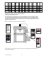
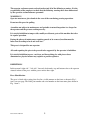
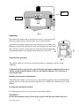
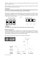
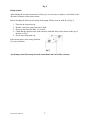
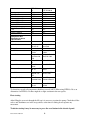
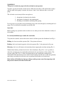
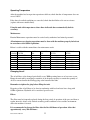
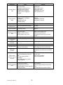
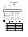
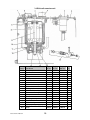
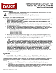
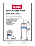
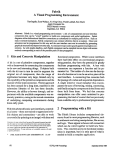
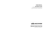
724 Robbins Road
Grand Haven, Michigan 49417
616-842-7110
Phone 800-937-3253
616-842-0859
Fax 800-846-3253
Web: www.dakecorp.com
E-mail: [email protected]
[email protected]
Dura Press Models
FORCE 40, 70 & 100
Dual voltage machines for 220 / 440 volts
Use and Maintenance Manual
Model No: _________________
Serial No: _________________
Force 40 70 100 Ton
1
Model
Max
Ton
Width
between
uprights
Width
between
table
channels
Max.
Ram
travel
Max.
Ram
to
table
Ram
rapid
advance
Ram
pressing
speed
Base
(W x D)
Height
Weight
FORCE
40
40
35"
8"
19"
37"
68 ipm
7 ipm
63" x 27"
88"
880
lbs.
FORCE
70
70
35"
8"
19"
37"
42 ipm
4 ipm
63" x 27"
88"
1100
lbs.
FORCE
100
100
41"
10"
19"
39"
52 ipm
3 ipm
75" x 33"
90"
2200
lbs.
Maximum operating pressure for all models 280 bars
Sound pressure maximum 78,6 db
For the safety of the operator/owner it is your responsibility to review the follow warnings
and safety labels located in this manual and on the machine. It is the responsibility of the
operator/owner to understand these labels. If there are any questions regarding these labels
call Dake at 1-800-937-3253.
Below is a diagram of where the safety labels are required.
Part number
76462
Part number
300168
Part
number
84935
Part number
84487
Part
number
84399
If at any time these safety stickers need to be replaced or are missing lock out the machine and
contact Dake immediately.
Force 40 70 100 Ton
2
The operator and owner must read and understand all of the following warnings. It is the
responsibility of the employer to check that the following warnings have been understood
by the operator and maintenance personnel.
WARNING!!!!
Operator must never place hands in the area of the ram during pressing operations.
Do not use this press for pulling.
A machine not subject to maintenance and periodic structural inspection is a danger for
the operator and the persons working near by.
It is strictly forbidden to tamper with, modify or elaborate parts of the machine that alter
its regular operation.
During the phases of maintenance requiring guards to be removed, machine must be
locked out according to local and state laws.
This press is designed for one operator.
All work requiring the piece to be pressed to be supported by the operator is forbidden.
It is strictly forbidden to press, cut, draw and do anything else with pieces whose
dimensions or physical nature may explode or produce splinters.
DEFINITIONS
In this manual “right side”, “left side”, forwards, backwards, top and bottom refer to the operator
situated in front of the press with the power unit to there right.
Press Identification
The press is fitted with a rating plate fixed in a visible manner on the front as shown in Fig. 1
item 1 on next page. The Dake part number and serial number on the front name plate shown in
Fig. 1 item 2.
Force 40 70 100 Ton
3
Item 1
Item 2
Unpacking
Fig. 1
The machine has shrink wrap on it and any accessories, spare part may be
Packed in cardboard boxes and positioned on top of the work table.
To remove the packing, cut the plastic wrap, taking care not to damage the
Machine or any part of it. Remove the accessories from the top of the work
table, check the contents correspond to the order and to the accompanying
documentation. Remove the lag bolts that hold the press to the skid.
Disposing of the packaging
Fig. 3
The packing will have to be disposed of be the purchaser in compliance with the current
regulations.
Claims shall not be accepted in the event of the goods not being in conformity with order or
with the accompanying documents if they are not notified within five days of the date of
receiving the goods.
Handling and transport and positioning
For handling the machine it is necessary to use special lifting equipment whose maximum lifting
capacity must be no lower than the total weight of the press which can be found on page 2 of this
manual.
Loading and unloading the machine
Use lifting straps are to be used to position as shown below in Fig 4.
WARNING!!!
Be sure the maximum capacity of each strap is greater than the total weight of the press.
Force 40 70 100 Ton
4
Do not make sudden movements when transporting the machine.
The manufacturer is not responsible for damage to the machine while loading or unloading the
press.
Pick up
here
Pick up
here
Fig. 4
Positioning the press
Simple precautions are necessary for correctly positioning the press always consider the safety
aspect not only in relation to the work carried out with the press, but also to the dangers
originated by the other machines in the workplace.
Do not position on unstable or unleveled floor.
Below in fig. 4 is the allowable distance from the wall, other machines or other objects.
Fig. 4
Commissioning and Starting
Electrical connection
This machine is dual voltage 220 3 phase / 440 3 phase. The amp rating on these machines are
6.8 amps on 220 volt 3 phase and 3.4 amp on 220 volt 3 phase.
WARNING!!!
Only a certified electrician that follows local and state laws is authorized to perform any
type of electrical connection on this machine. The electrical power supply voltage must be
made in compliance with local and state laws.
Force 40 70 100 Ton
5
For proper operation it is necessary to ensure constant voltage and it must not exceed or be lower
than 5% of the rated value.
Before making any electrical connection confirm voltage rating of the machine. There is a black
plastic box mounted on top of the reservoir.
WARNING!!!
Be sure there is no power to the machine before checking the following connections. It may
be necessary to lock out the machine for proper power disconnection.
Remove the two mounting screws that hold this box in place. Under this box you will see one of
the following possibilities in fig. 5. After confirming or changing this to the correct voltage
mount the cover with the two screws. Now, open the electrical panel on the transformer be sure it
is set for the correct output voltage.
Fig. 5
220 Volt connection
440 volt connections
WARNING!!!
Any damage caused by a faulty electrical connection is not covered by warranty.
Filling the pumping unit
To fill the pumping unit, use exclusively the oils indicated in the table on the next page or
equivalent. The environmental conditions must be considered before purchasing oil. To transfer
the oil from the container to the tank use an external filter as shown in Fig. 6 in order to prevent
the introduction of foreign material or liquids at the time of filling.
The amount of oil required for each model is described in the chart below.
40 Ton
70 ton
100 Ton
10.5 Gallons
10.5 Gallons
15.5 Gallons
A - Oil
Force 40 70 100 Ton
B - Pump
6
C - Filter
D - Press Oil
Fig. 6
Pump rotation
After making the electrical connections to the press it is necessary to make a visual check on the
direction of rotation of the electric motor.
Before checking the direction of rotation of the pump, fill the reservoir with oil see Fig. 6
1.
2.
3.
4.
Unscrew the inspection cap.
Identify a reference point on the drive shaft.
Power up the motor for Max. 1-2 seconds.
Check that the rotation of the shaft coincides with that of the arrow shown on the top of
the unit see Fig 7.
5. Screw down inspection cap.
If the motor rotates in the wrong direction:
See your electrician.
Fig. 7
Any damage caused by wrong electrical connection is not covered by warranty
Force 40 70 100 Ton
7
Gravity
Maximum Pour
Flash Point
Viscosity @ 100 F.
Viscosity @ 130 F.
Viscosity @ 210 F.
Color
Viscosity Index
Also Passes ASTM Rust
Test
Oiliness Additive
DTE Oil No.
24
31
20 F.
395 F
145-160
84.5
44
3 Max.
95 Min.
DTE Oil No.26
26
20 F
400 F.
290-310
144
53
3.5 Max.
95 Min.
Yes
Yes
Yes
Yes
Pacemaker Oil
NO. XD 15
Nuto H32
Harmony No.
43 AW
Puropale Rx
Anti Wear No.
150
Pacemaker Oil
No. XD30
Nuto H68
Harmony No.
54AW
Puropale Rx Anti
Wear No. 300
Tellus Oil No.
32
Duro Oil
AW16
Rycon Indl Oil
No. 15
Sunvis No.
706 No. 816
WR
No. 475
Diamond Roza
L
Tellus Oil No. 68
Rycon Indl Oil
No. 31
Sunvis No. 754
No. 831 WR
Rando Oil No.
HD-32
Rando Oil No.
HD-68
Competitive Oils
Equivalent to above
specifications
Cities Service
Exxon Co.
Gulf Oil Co.
Pure Oil Co.
Shell Oil
Sinclair Oil
Standard Oil
Sun Oil Co.
Sunray DX Oil Co.
Texaco
Duro Oil AW31
No. 477
Diamond Roza H
To obtain best results oil temperature should not exceed 140 F. When using DTE No. 26 as an
Alternative for DTE No. 24 there might be a slight variation in the ram speeds.
First starting
After filling the reservoir through the fill cap it is necessary to prime the pump. Check that all the
valves and distributors are in the rest position, at the time of starting do not operate any
movement.
To obtain starting it may be necessary to press the reset button in the electrical panel.
Force 40 70 100 Ton
8
WARNING!!!
This press is exclusively prepared to be used only by one operator.
To prime, jog the start button (electric motor). When the unit emits a dull sound with no jumps
and the sound of the pump is constant. An uneven “tinny” noise indicates there is air in the
pump.
The oil in the reservoir may fall on start up due to:
1. absorption of volume by the cylinder
2. Absorption of volume by the pumping unit.
3. Discharge of air bubbles remaining in the piping.
It is necessary to top off the level of oil bringing it up to the correct height, by checking the level
gauge. The level should be about half way up the stick.
Operation
Before starting any operations make sure there are no other persons in the immediate vicinity of
the machine.
It is strictly forbidden to pass under the work table.
To operate the cylinder, activate the master switch, and then operate the distributor lever Fig. 8.
Pulling - the lever toward the operator (Pos. 2) the piston rod lowers.
Pushing - the lever from the opposite side to the operator (Pos. 3) the piston rod will go up.
Releasing - the lever will return to the neutral position stopping the ram from moving (Pos. 1).
With the hand wheel positioned on the side of the distributors (Fig. 8 Pos. 4) it is possible to
adjust the operating pressure continually and therefore the pressing force of the cylinder. The
pressure gauge (Fig. 7 Pos. 5) allows displaying the pressure during the working phases.
Adjustment of the maximum pressure must be made starting from the lower value and gradually
increasing to reach the pressure necessary to perform the operation to be carried out.
Dake declines all liability for damage to things and/or persons caused by tampering with
the pressure control valve fitted on the unit.
Force 40 70 100 Ton
9
Fig. 8
Work table height adjustment
To optimize the use of the press it is necessary to set the work table at a convenient height in
relation to the operation to be carried out and to the equipment to be used.
Before proceeding to lift the mobile table, check that:
- The eyebolts fixed to the work table are fully tightened Pos. 01.
- The eyebolt support (nose piece) is properly screwed onto the cylinder ram (Pos. 2)
- The eyebolts fixed to the nose piece are fully tightened.
1. Hook the chains (Pos. 5) to the respective eyebolts and lift the cylinder ram until the
chains are set under tension but, do not lift the table.
2. Check the chain connections to all eyebolts to ensure a safe secure connection.
3. When the connection is safe, lift the table just above the desired table height.
4. Take the split pins (Pos. 6) off the pins then remove the pins.
5. Insert the pins to the desired work table height pin location then, insert the split pins.
6. Slowly move the table down until it rests on the table pins.
7. Check to be sure the position and the assembly of the pins are correct.
8. Unhook the chains and leave them hang in a downward position (Pos. 5).
Pos. 6
Pos. 2
Pos. 3
Pos. 1
Pos. 5
Force 40 70 100 Ton
10
Operating Temperature
After the machine has been put into operation at full rate, check that the oil temperature does not
exceed 140 F.
If the above described conditions are exceeded, check that the fluid used is not too viscous
(replace with more suitable fluid).
Using the unit with temperatures above those indicated above automatically forfeits
warranty.
Maintenance
Routine Maintenance operations must be carried out by authorized and trained personnel.
All maintenance or cleaning operations must be done with the machine properly locked out
in accordance with OSHA regulations.
Below is a table with the normal times for maintenance work:
HOURS
50
100
300
500
1000
1500
2000
CHECK OIL
FILTER
YES
CHECK
OIL
CHANGE
OIL
CHANGE OIL
FILTER
CHANGE AIR
FILTER
YES
YES
YES
YES
YES
YES
YES
YES
YES
YES
YES
YES
YES
Changing the oil
The oil will have to be changed periodically every 2000 operating hours or at least once a year.
Empty the unit tank by arranging a container of an adequate capacity to contain the quantity of
oil to be removed under the drainage plug at the bottom of the tank.
Remember to tighten the plug before filling the tank.
Disposing of the oil will have to be done in conformity with local and state laws along with
OSHA regulations. Hydraulic oil is considered special waste.
Filters
The filter must be frequently replaced during the first period of operation of the press and then at
regular intervals of time to be defined according to the conditions of use and the environment
where the machine is located.
It is recommended to change the filter after the first 100 hours of operation. After that
approximately every 500-600 hours.
Force 40 70 100 Ton
11
On this unit there are three filters:
- Oil outlet filter
- Oil inlet filter
- Air inlet filter
Replacing the filters will help give the pump, oil and generally all the moving components longer
service life.
Failure to comply with the maintenance table in changing the filter will forfeit the
warranty.
Force 40 70 100 Ton
12
Malfunction
Origin
Air in the pump.
Air in the circuit
Damaged cylinder gaskets
Damaged or worn pump
Sequence valve jammed
Delivery oil line clogged or
choked
Remedy
Bleed the air
Bleed the air
Replace the gaskets
Replace the pump
Recondition seq. valve
Check hydraulic lines
Electric motor will not turn
Piston gaskets completely
Damaged
Blocked distributor
Damaged pump
Check motor
Replace
Recondition distributor
Recondition or replace
Head gaskets damaged or worn
Lack of pressure from pump
Pressure control valve set low
Filter Suction clogged
Fluid too viscous
Fluid level too low
Fluid unsuitable
Fittings or joints let air in
Air discharge in the circuit
Replace
Recondition pump
Set valve
Clean or replace
Replace
Bring back up to correct level
Replace with suitable fluid
Replace or tighten fittings
Discharge the remaining air from the
system
Worn or damaged
Operating instability
Recondition or replace
Replace or recondition
Pumps worn or damaged
Replace and recondition
Pump joint broken or undone
Valve seat damaged
Pressure not constant
Dirty fluid
Check or replace
Replace or recondition
Check pump or pressure relief valve
Drain off fluid clean system and
components refill with clean and filtered
fluid
Piston moves
irregularly or will
not move
Lack of pressure from the pump
Pressure adjustment valve set
low
The translating cylinder is
damaged
Translating wheels or guides
dirty or blocked
Recondition the pump
Set the valve
Check and recondition
Clean or replace parts
Excessive wear on
parts
Oil containing abrasives
Insufficient lubrication
High operating pressure
Foreign bodies in the oil not held
back by the filter
Replace the fluid
Poor quality oil
Lowe the setting of the pressure relief
valve
Insufficient filtering, replace the filters
Cylinder moves
slow
Piston will not
move
Cylinder leaks oil
Piston ram will not
build pressure
Pump Cavitation
Foam forms in the
fluid
Pumps
Pressure relief
valves
Pumps deliver little
or no oil
Pump will not turn
Unstable valves
Valve parts
jammed
Force 40 70 100 Ton
13
Putting out of service
In the case of not operating for a long period it is necessary to disconnect the press from the
sources of electrical power supply.
Empty the unit of oil and protect it suitably so there is no dust, moisture or other foreign bodies
that can damage the parts of the unit.
Demolition and division of materials
If you are not going to use the machine any more, it is recommended to make it inoperative by
removing the oil contained in the tank and eliminating the oil remaining in the cylinder,
hydraulic lines, pump body and valves.
When going for demolition the press must be treated as special waste, it must therefore be split
up into its homogeneous parts, these parts must be separately disposed of in conformity with
local and state laws along with all OSHA regulations.
Force 40 70 100 Ton
14
Electrical box Parts breakdown
1
2
3
4
Item #
1
2
3
4
5
6
7
7A
8
Part Name
Pump Start button
Stop button
Start button
Emergency button
Power light
Main power switch
Elect. Box lock
Door key
Female plug
N/A
Male plug
Electrical box w/ all
components
Electrical box w/ no
components
N/A
N/A
Force 40 70 100 Ton
5
6
15
7
Part
number
716542
716539
716556
300351
300298
80554L
300628
80511
8
Qty.
1
1
1
1
1
1
1
1
301547
1
300387
1
300389
1
Electrical box components parts
1
2
Item #
1
2
3
3
3A
4
5
5B
6
6A
Force 40 70 100 Ton
3
4
Part Name
Contactor
Transformer
Overload 220 volt
Overload 440 volt
N.O. contact block
Relay
Fuse block
Fuse 2 amp
Terminal block ground
Terminal block black
5
6
40 Ton
70 Ton
100 Ton
300842
302187
302189
302192
72300000
300843
77523
300842
302187
302189
302192
72300000
300843
77523
300842
302187
302188
302192
72300000
300843
77523
16
Qty
1
1
1
1
1
1
1
3
2
3
2.6 Exchange valve
Item #
1
N/A
N/A
Force 40 70 100 Ton
Part Name
Complete relief valve
O-ring kit spring
washer
Valve handle
Part #
40 Ton
300178
Part #
70 Ton
300178
Part #
100 Ton
300178
Qty
1
1
301393
17
301393
301393
1
2.5 Distributor section
Item #
N/A
1, 2, 3, 4,
5
6, 9, 10
Not shown
7
8
11, 12, 13
Force 40 70 100 Ton
Part Name
Complete valve assembly
Knob lever pin fork powder
scraper
Shaft group cap group main
body
Relief valve
Cover Body
Gasket Set
Back valve body entry
collector body max valve
18
Part
number
300179
302211
302210
300852
302209
300886
302208
Qty
1
1
1
1
1
1
1
Cylinder breakdown
8
4
7
1
2
Item #
1
2
3
4
5
6
7
8
8A
Not
shown
Not
shown
Not
shown
Force 40 70 100 Ton
Part Name
Piston Gasket
Piston 0-ring
Head guide rings
Head o-ring
Head gasket
Head scraper
Washer
Hose fitting top
Hose fitting bottom
Complete cylinder
Gauge
Hydraulic hose B
port
Hydraulic hose A
port
3
5
Part#
Part#
Part#
40 Ton
70 Ton
100 Ton
300609
301195
301189
300610
301196
301186
300647
301197
301187
300648
301198
301188
300649
301199
301185
300650
301200
301184
Washer comes with fitting
301390
301390
301390
301390
301390
301390
300698
300642 SS100C00
6
Qty
1
1
1
1
1
1
2
2
2
1
300359
300360
1
300382
300382
1
300383
300383
1
19
2.4 Hydraulic pumping unit
Item #
1
1
2
3
4
5
6
7
*8
*9
8 9 11
10
*11
12
13
14
15
16
N/A
Force 40 70 100 Ton
Part #
40 Ton
300633
301388
300388
302055
300391
300392
Part Name
Complete power unit
Tank cover
Electrical cover
Fill cap
Air filter
Drain filter
Back motor bearing
Motor rotor
Driving shaft
Drive shaft assembly
Front motor bearing
Pump motor
Blade
Pumping bearing
Eccentric
Roller bearing
High pressure pump group
Outlet filter / on bottom of
pump
Part#
70 Ton
300633
301388
300388
302055
300635
300392
301848
301848
302200
302200
Part
#
100 Ton
79937
301391
300388
302055
300224
300223
Qty
1
1
1
1
1
1
1
1
1
302056
302056
301115
301115
301115
1
1
1
1
1
1
2
300393
300393
300394
1
20
Hydraulic diagram
Force 40 70 100 Ton
21
Electrical schematic
Force 40 70 100 Ton
22
DURA PRESS
Gauge Conversion
Force 40
Bore 120 mm = 4.73 =
40 Tons
35 Tons
30 Tons
25 Tons
20 Tons
15 Tons
10 Tons
5 Tons
1 Ton
Force 40 70 100 Ton
=
=
=
=
=
=
=
=
=
314 Bar
275 Bar
235 Bar
196 Bar
157 Bar
117 Bar
78 Bar
39 Bar
7.8 Bar
23
=
=
=
=
=
=
=
=
=
4555 PSI
3986 PSI
3416 PSI
2847 PSI
2277 PSI
1708PSI
1138 PSI
569 PSI
114 PSI
DURA PRESS
Gauge Conversion
Force 70
Bore 160 mm = 6.299
70 Tons
65 Tons
60 Tons
55 Tons
50 Tons
45 Tons
40 Tons
35 Tons
30 Tons
25 Tons
20 Tons
15 Tons
10 Tons
5 Tons
1 Ton
Force 40 70 100 Ton
=
=
=
=
=
=
=
=
=
=
=
=
=
=
=
299 Bar
278 Bar
256 Bar
235 Bar
214Bar
192 Bar
171 Bar
150 Bar
128 Bar
110 Bar
88 Bar
66 Bar
44 Bar
22 Bar
4.4 Bar
24
=
=
=
=
=
=
=
=
=
=
=
=
=
=
=
4493 PSI
4172 PSI
3851 PSI
3530 PSI
3209 PSI
2888 PSI
2567 PSI
2246 PSI
1925 PSI
1605 PSI
1284 PSI
963 PSI
642 PSI
321 PSI
64 PSI
DURA PRESS
Gauge Conversion
Force 100
Bore 180 mm = 7.086 =
100 Tons
95 Tons
90 Tons
85 Tons
80 Tons
75 Tons
70 Tons
65 Tons
60 Tons
55 Tons
50 Tons
45 Tons
40 Tons
35 Tons
30 Tons
25 Tons
20 Tons
15 Tons
10 Tons
5 Tons
1 Ton
Force 40 70 100 Ton
=
=
=
=
=
=
=
=
=
=
=
=
=
=
=
=
=
=
=
=
=
350 Bar
332 Bar
315 Bar
297 Bar
280 Bar
262 Bar
245 Bar
227 Bar
210 Bar
192 Bar
175 Bar
157 Bar
135 Bar
122 Bar
105 Bar
87 Bar
70 Bar
52 Bar
35 Bar
17 Bar
3.4 Bar
25
=
=
=
=
=
=
=
=
=
=
=
=
=
=
=
=
=
=
=
=
=
5074 PSI
4820 PSI
4566 PSI
4312 PSI
4058 PSI
3805 PSI
3551 PSI
3298 PSI
3044 PSI
2790 PSI
2536 PSI
2283 PSI
2028 PSI
1775 PSI
1522 PSI
1268 PSI
1014 PSI
761 PSI
507 PSI
253 PSI
50 PSI