1
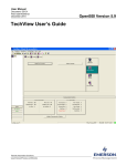
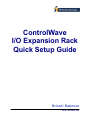
ControlWave
I/O Expansion Rack
Quick Setup Guide
Bristol Babcock
D5122 – December, 2005
The information in this document is subject to change without notice. Every effort has been
made to supply complete and accurate information. However, Bristol Babcock assumes no
responsibility for any errors that may appear in this document.
Bristol Babcock does not guarantee the accuracy, sufficiency or suitability of the software
delivered herewith. The Customer shall inspect and test such software and other materials to
his/her satisfaction before using them with important data.
There are no warranties, expressed or implied, including those of merchantability and fitness for
a particular purpose, concerning the software and other materials delivered herewith.
Bristol is a registered trademark of Bristol Babcock. Other trademarks or copyrighted products
mentioned in this document are for information only, and belong to their respective companies,
or trademark holders.
Copyright (c) 2005, Bristol Babcock, 1100 Buckingham St., Watertown, CT 06795. No part of
this manual may be reproduced in any form without the express written permission of Bristol
Babcock.
2
IMPORTANT! READ INSTRUCTIONS BEFORE STARTING!
Be sure that these instructions are carefully read and understood before any
operation is attempted. Improper use of this device in some applications may result
in damage or injury. The user is urged to keep this book filed in a convenient
location for future reference.
These instructions may not cover all details or variations in equipment or cover
every possible situation to be met in connection with installation, operation or
maintenance. Should problems arise that are not covered sufficiently in the text, the
purchaser is advised to contact Bristol Babcock for further information.
EQUIPMENT APPLICATION WARNING
The customer should note that a failure of this instrument or system, for
whatever reason, may leave an operating process without protection. Depending
upon the application, this could result in possible damage to property or injury to
persons. It is suggested that the purchaser review the need for additional backup
equipment or provide alternate means of protection such as alarm devices, output
limiting, fail-safe valves, relief valves, emergency shutoffs, emergency switches, etc.
If additional information is required, the purchaser is advised to contact Bristol Babcock.
RETURNED EQUIPMENT WARNING
When returning any equipment to Bristol Babcock for repairs or evaluation,
please note the following: The party sending such materials is responsible to ensure
that the materials returned to Bristol Babcock are clean to safe levels, as such levels
are defined and/or determined by applicable federal, state and/or local law
regulations or codes. Such party agrees to indemnify Bristol Babcock and save
Bristol Babcock harmless from any liability or damage which Bristol Babcock may
incur or suffer due to such party's failure to so act.
ELECTRICAL GROUNDING
Metal enclosures and exposed metal parts of electrical instruments must be
grounded in accordance with OSHA rules and regulations pertaining to "Design
Safety Standards for Electrical Systems," 29 CFR, Part 1910, Subpart S, dated: April
16, 1981 (OSHA rulings are in agreement with the National Electrical Code).
The grounding requirement is also applicable to mechanical or pneumatic
instruments that include electrically-operated devices such as lights, switches, relays,
alarms, or chart drives.
Before You Begin
This guide is intended to help you get 'up-and-running' with a minimal amount of effort. It does
NOT, however, tell you everything you need to know about setting up and configuring a
ControlWave I/O Expansion Rack. We have included references throughout this book to other
places in the documentation set, where you can get more details on a particular subject.
Throughout your configuration activities, please be aware of the following items:
Shock Hazard! Always follow accepted safety guidelines. As with all electronic devices,
improper installation, grounding, or usage can cause an electrical shock. If you have any doubts
about how to install, ground, and use this product safely, please consult a qualified electrician.
Electrostatic Discharge (ESD) - Sensitive electronic devices such as this can be damaged by
electrostatic discharge. Please follow accepted ESD guidelines.
If You Need Help…
If you're having problems setting up and configuring this unit, please call our ControlWave
Application Support team at (860) 945-2394 or (860) 945-2286 for assistance. Help is available
Monday through Friday 8:00 AM to 4:30 PM Eastern Time, excluding holidays, and scheduled
factory shutdowns.
4
Table of Contents
Introduction..................................................................................................................................... 6
Setting up the Hardware........................................................................................................... 7
Setting Configuration Parameters ............................................................................................ 7
Setting up the Host to Reference the I/O Expansion Rack ...................................................... 7
Setting Up the Hardware................................................................................................................. 8
Setting Configuration Parameters ................................................................................................. 12
Establishing Communications Using LocalView .................................................................. 12
Signing On in the Flash Configuration Utility ....................................................................... 14
Defining an Ethernet Port....................................................................................................... 15
Defining IP Parameters .......................................................................................................... 16
Setting Application Parameters.............................................................................................. 17
Power Fail Timeout................................................................................................................ 17
Host Comm Loss Timeout ..................................................................................................... 18
Saving Your Configuration Parameter Changes to the I/O Rack........................................... 20
You MUST power-off then re-start to activate the newly saved parameters......................... 20
Setting up the Host to Reference the I/O Rack ............................................................................. 21
Configuring the I/O Boards in ControlWave Designer.......................................................... 21
Select List of Boards: ............................................................................................................. 22
Configure Selected I/O Boards: ............................................................................................. 23
5
Introduction
Introduction
The I/O capacity of the ControlWave Process Automation Controller can be increased by the
addition of one or more ControlWave I/O Expansion Racks.
The ControlWave Controller is referred to as the host of the I/O Expansion Racks.
Communication between the I/O Expansion Rack and its host ControlWave is via Ethernet. The
I/O Racks can be part of their own IP sub-net, or they can sit on the wider Ethernet network,
depending upon the requirements of your particular application.
More than one ControlWave can reference a single I/O Rack (necessary for redundant
configurations) however, only one ControlWave can use an I/O Rack at any one time.
NOTE: The I/O Expansion Rack can be distinguished from the Process Automation Controller
by looking for the Run/Remote/Local key switch. On the I/O Rack, there is no key switch, simply
a plug where the keyhole would appear.
ControlWave Process
Automation Controller
(HOST)
Ethernet cabling
ControlWave
Expansion I/O Rack
ControlWave
Expansion I/O Rack
6
Introduction
The configuration process for the I/O Expansion Rack is divided up into 3 parts.
Setting up the Hardware
This section gives you a quick overview of how to unpack the I/O Expansion Rack, install
the modular components, set the switches, and connect the cable between the rack and the
PC. References are included to the hardware manual for details of the individual steps.
Setting Configuration Parameters
This section describes how to establish communications with the rack using LocalView, and
how to use the Flash Configuration Utility to specify an Ethernet Port for the rack. This
section also discusses how to set up certain IP and application parameters.
Setting up the Host to Reference the I/O Expansion Rack
This section shows how to use the I/O Configuration Wizard in ControlWave Designer to
modify the ControlWave Project in the host controller, so that it can make use of the boards
in the I/O Expansion Rack.
7
Setting up the Hardware
Bezel
Port80
Display
(Plastic bezel covers the
power supply sequencer
module in slot 1 and CPU
module in slot 2.)
Chassis
Serial Port COM1
Chassis
Serial Port COM2
Ethernet Port 1
I/O Modules
(install in chassis
slots 3 to 10)
Bezel Door
(for access to power
switch and PSSM
LEDs)
Setting Up the Hardware
This involves unpacking the ControlWave I/O Expansion Rack hardware, mounting the chassis,
installing I/O modules, wiring I/O terminations, making proper ground connections, connecting a
communication cable to the PC workstation and setting switches.
1. Remove the Chassis from its carton and install it at its assigned work site. (see Section 2.3.1
of CI-ControlWaveEXP).
2. Remove the Power Supply Sequencer Module (PSSM) from its carton and install it into
Chassis slot 1, i.e., the first slot from the left end of the installed unit. (see Section 2.3.2 of
CI-ControlWaveEXP).
8
Setting up the Hardware
3. Remove the CPU Module from its carton and install it into Chassis slot 2, i.e., the second slot
from the left end of the installed unit. CPU Module DIP Switches may be configured before
or after the module has been installed into the Chassis. (see Section 2.3.3. of CIControlWaveEXP).
Reset
Switch
Port 80
Display
SW1
Comm.
Port 1 (J1)
SW3
Lithium
Battery
3.6V
950mA-hr
½ AA Cell
Comm.
Port 2 (J2)
Ethernet
Port 1 (J3)
Leave all SW3
CPU switches
in default 'OFF'
position, except
for #4.
Enlarged detail
of CPU switch
banks
(CAPITALIZED entry
indicates ON position)
Diagnostics DISABLE / enable
UNIT A / unit B
Redundancy DISABLE / enable
static memory RETAIN / initialize
NORMAL / updump
Soft switches USE / ignore
Soft switches write UNLOCK / lock
Watchdog circuit ENABLE/disable
ENABLE/disable battery backup
recovery mode ENABLE/disable
Unused
Unused
SW3
SW1
(CAPITALIZED entry
indicates ON position)
By default, SW1
switches should
all be 'ON' unless
this rack is part of
a redundant pair.
NOTE: For the initial configuration activities described in this manual, we recommend you leave
most of the CPU switch settings in their default positions, as set at the factory:
9
Setting up the Hardware
•
Switch bank SW1: all switches in the ON position, unless this I/O rack is part of a
redundant pair. (A redundant pair would require two I/O Expansion Racks, hooked
through a ControlWave Redundant I/O Switcher (CWREDIO) to the host
ControlWave unit(s).)
If this I/O rack is part of a redundant pair, set switch SW1-6 and SW1-7 as shown in
the table, below:
For these switches:
SW1-6
SW1-7
If this I/O Expansion Rack is part of a
redundant pair…
This must be set OFF.
This switch must be set either ON or OFF
based on whether this is the "A" I/O rack or the
"B" I/O rack of this redundant pair.
•
•
•
SW1-7 must be ON if this is the "A" rack
SW1-7 must be OFF if this is the "B" rack
Switch bank SW3: all switches in the OFF position, except SW3-4, which you will
want to set to the ON position to enable the backup battery when the I/O Expansion
Rack is ready to be put into service. If the rack is NOT going to be put into service for
an extended period of time, leave this OFF to avoid draining the battery.
4. For the configuration activities, described in this manual, we will use Serial Communication
Port 2 (COM2) on the rack, which is configured by default for 9600 baud. (For more
information on communication ports see Section 2.3.3.2 of CI-ControlWaveEXP).
•
•
Plug one end of an RS-232 null modem cable1 into one
of your PC communication ports.
Plug the other end of the RS-232 null modem cable
into Serial Communication Port 2 (COM2) of the I/O
Expansion Rack
Plug RS-232
null modem
cable into
COM2
5. Remove I/O Modules from their cartons and install them into the Chassis. I/O Modules
reside in slots 3 through 4, 3 through 6 or 3 through 10 for units supporting 2, 4 or 8 I/O
Modules respectively. Install I/O wiring to each I/O Module (see Section 2.3.4 of CIControlWaveEXP).
1
For a wiring diagram of an RS-232 null modem cable, see Figure 2-8 in the CI-ControlWave manual.
10
Setting up the Hardware
6. Install a ground wire between the Chassis Ground Lug and a known good Earth Ground (see
Section 2.3.1.1 of CI-ControlWaveEXP).
7. Install Watchdog /MOSFET Redundancy Switch wiring (see Section 2.3.5.3 of CIControlWaveEXP). (OPTIONAL - perform this step only if you want to use this feature.)
8. Connect Bulk DC Power to the PSSM Module (see Section 2.3.5.1 and Section 2.3.5.2 of CIControlWaveEXP).
Typical Configurations
+12Vdc Bulk Supply #1 Pos. Term.
+12Vdc Bulk Supply #1 Neg. Term.
Chassis Ground
+24Vdc Bulk Supply #1 Pos. Term.
+24Vdc Bulk Supply #1 Neg. Term.
Chassis Ground
1 +VIN
+VINF
Shared +12Vdc Power Supply
-VIN
-VINF
5 CHASSIS
1 +VIN
+VINF
Shared +24Vdc Power Supply
-VIN
-VINF
5 CHASSIS
9. Install the Bezel so that it covers the PSSM and CPU Modules (see Section 2.3.7 of CIControlWaveEXP).
10. Plug an Ethernet connection from your network into the
Ethernet port of the I/O Rack.
11. Open the Bezel door, and apply power to the I/O Expansion
Rack by setting the Power Switch on the PSSM Module to the
‘1’ position.
12. When the ControlWave I/O Expansion Rack completes its
power-on sequence, the Port 80 display should be blank.
11
Eth erne t
Port
Setting Configuration Parameters
Setting Configuration Parameters
Establishing Communications Using LocalView
Before you begin, you must plug a cable from a serial port on your PC running Open BSI, to
serial port COM2 on the I/O Expansion Rack.
1. Click as follows: StartÆProgramsÆOpenBSI ToolsÆLocalView
2. Choose 'Local' for the mode, enter a name for the LocalView file, and click on [Create].
First, choose
'Local' as
the mode.
Next, enter a
name for this
LocalView
file.
Finally, click
on [Create]
3. Choose the communication port on the PC workstation which you will use to communicate
with the ControlWave I/O Expansion Rack. Then, specify the baud rate for that port, and
click on the [Next>] button.
Choose the communication port on the PC
workstation (NOT on the Expanded I/O Rack)
Specify the baud rate for that port
Finally, click on [Next>]
12
Setting Configuration Parameters
4. First, turn off auto local address detection by answering "No" to the question. Then specify
'1' as the local address, and 'CWave_RIO' as the RTU type. Finally, click on [Finish].
Turn off auto local address detection
Choose
'CWave_RIO'
Use "1" as the local address
Finally, click on [Finish]
5. At this point, LocalView will create a temporary network with a single 'RTU'. Right-click on
the icon, then choose RTUÆ RTU Configuration Parameters from the pop-up menus.
This will call up the Flash Configuration Utility.
Right-click on the ‘CWave_RIO’ icon
13
Setting Configuration Parameters
Signing On in the Flash Configuration Utility
Tabs for
calling up
other pages
You must click here to sign-on
with a username and password
in order to access any flash
parameters.
For purposes of this configuration we are leaving the
local address at a value of "1". If we were configuring
I/O racks which communicated via MODBUS, the
local address would be used as the MODBUS slave
address.
Enter the username and password and click on
[OK].
Once you have signed on, you can proceed to:
•
•
•
•
•
Define an Ethernet Port
Define IP Parameters
Define Application Parameters
Save Changes to the I/O Rack
Turn off the I/O rack and re-start it
These steps will be covered in the pages which follow.
14
Setting Configuration Parameters
Defining an Ethernet Port
When you have successfully signed on, click on the "Ports" tab. On the 'Ports' page, you must
now define an Ethernet Port. Select the ENET1 port, then enter an IP address in "IP ADDR A"
and an "IP MASK" to define the valid range of IP addresses to which this port can send data.
Next, enter an IP address,
then enter an IP mask
to define the valid range
of IP addresses to which
this port can send data.
First, you must select the
Ethernet Port (ENET1).
For an explanation of IP addresses and IP masks, see Chapter 1 of the Open BSI Utilities Manual
(document# D5081).
IMPORTANT
In newer ControlWave units, all Ethernet ports are pre-programmed at the factory with initial IP
addresses and masks. For the I/O Expansion Rack’s Ethernet port, the initial address and mask are:
ETH1
IP Address: 10.0.1.1
IP Mask: 255.255.255.0
Because each unit shipping from the factory will have these initially pre-programmed, you should
only use this address for ‘bench’ testing and configuration. This address must be changed before
putting the unit on an actual network, since an address conflict would exist as soon as the second unit
was placed online.
15
Setting Configuration Parameters
Defining IP Parameters
Click on the 'IP Parameters' tab, and specify the IP address of the host ControlWave controller in
the "IP ADDR A" field; NOT the Network Host PC (NHP).
If another ControlWave controller serves as a redundant standby unit for the host controller,
enter the redundant unit's IP address in the "IP ADDR B" field.
For the I/O rack, this is the IP address
of the host ControlWave controller;
not the Network Host PC
NOTE: For more information on what the other parameters on this page mean, please refer to
Chapter 5 of the Open BSI Utilities Manual (document# D5081).
NOTE: The “Challenge Protocol Default Username” refers to a username defined on the
‘Security’ page of the Flash Configuration utility. The same combination of the
username/password defined on that page must also be defined in the host ControlWave unit in
order for a successful sign-on, and communications between the host and the I/O rack. If no
default username, is assigned, the system will attempt to use, “SYSTEM” and “666666” as the
username/password, and failing that, the first defined username/password combination in the
system. Redundancy, PAP/CHAP protocols, and host-to-I/O rack communications all make use
of this username/password combination.
16
Setting Configuration Parameters
Setting Application Parameters
Click on the 'Application Parameters' tab.
This timeout determines
what happens to output
values when the I/O rack's
power is restored following
a power failure.
This timeout determines
what happens to output
values when the I/O rack
loses communications
with its host controller.
Timeouts
Power Fail
Timeout
If the I/O rack loses power, and static memory is configured to
RETAIN values (SW1-5 set ON), the "Power Fail Timeout" specifies
how the I/O rack will handle output values when power is restored. The
function of the Power Fail Timeout is described in the table, below:
Value of "Power Fail
Timeout"
Power Fail Timeout is
set to 0 seconds.
Affect on outputs when power is restored
DOs will be set to 0 (FALSE).
AOs will be set to the "User Configured
Output" value, if any.
If the amount of time the power was off is less
than the specified Power Fail Timeout, outputs
are set to the last state they were in prior to the
power failure.2
Power Fail Timeout is
set to a value greater
than 0 and less than
65,535 seconds.
2
The last state is stored in static memory.
17
Setting Configuration Parameters
If the amount of time the power was off is
greater than the specified Power Fail Timeout,
DOs will be set to 0 (FALSE), and AOs will be
set to the "User Configured Output" value.
Power Fail Timeout is
set to 65,535 seconds.
AOs and DOs will be set to the last state they
were in prior to the power failure.2
NOTE: In the event of a Watchdog failure (CPU failure, but power is not
lost), AOs will be set to the "User Configured Output". When the system
attempts to restart, and if the restart is completed before expiration of the
Power Fail Timeout, AOs will then be set to the last output they had prior
to the Watchdog failure.
Host Comm Loss
Timeout
The Host Comm Loss Timeout determines how certain outputs are
affected if the I/O Rack loses communications with its host
ControlWave controller. Enter a time in seconds.
If you enter a value of 0 for the "Host Comm Loss Timeout", outputs
will be left unchanged in the event communications are lost with the
host.
The table, below, describes how the length of time communications are
lost affects the outputs:
Length of Time Communication
was lost with the Host Controller
If the communications were down
for less than or equal to the Host
Comm Loss Timeout…
If communications were down for
more than the Host Comm Loss
Timeout
Affect on Outputs
Do not change outputs
DOs are set to 0 (FALSE), and
AOs are set to the "User
Configured Output" value.
IMPORTANT: The affect on outputs (see table above) via the Host Comm
Loss Timeout feature is suspended if “Serial Failover Enabled” is
checked, and serial MODBUS communications are functioning. If
communications with the host are lost and serial MODBUS
communications fail as well, and the Host Comm Loss Timeout has
expired, however, outputs will be set according to the table, above.
18
Setting Configuration Parameters
Redundancy Transfer
Unit A Addr
This must be an IP address corresponding to an Ethernet port on the
‘A’ I/O Expansion Rack in a redundant pair.
Unit B Addr
This must be an IP address corresponding to an Ethernet port on the
‘B’ I/O Expansion Rack in a redundant pair.
MODBUS Write Access
Serial Failover
Enabled
Normally, should communications be lost between the host
ControlWave and the I/O Expansion Rack, the I/O points are set to the
‘safe’ state described under “Host Comm Loss Timeout”. When
“Serial Failover Enabled” is checked, however, write control through
serial MODBUS communications are allowed with the I/O Expansion
Rack, even though communications with the host ControlWave have
been lost. This allows control operations to continue via the I/O rack,
until Ethernet communication with the host can be re-established.
This is also true in cases where a redundant pair of I/O Expansion
Racks have been configured; a failover from the on-line rack to the
standby rack will not occur just based on a loss of communications
with the host, if serial MODBUS communications are still active.
In order for the “Serial Failover Enabled” feature to work, MODBUS
communications must have been fully pre-configured, and ready to use
when communications are lost with the host. If serial MODBUS
communications fail, and the user configured “Host Comm Loss
Timeout” has expired, all outputs will be set according to the “Host
Comm Loss Timeout” description, above.
NOTE: Serial MODBUS read requests are unaffected by the “Serial
Failover Enabled” check box. Reads are always allowed. Serial
MODBUS writes are only allowed when “Serial Failover Enabled” is
checked.
The “Serial Failover Enabled” feature requires firmware 04.00 or
newer.
19
Setting Configuration Parameters
Saving Your Configuration Parameter Changes to the I/O Rack
To save your configuration
changes, click on the [Save to
Rtu] button. This button saves
ALL entries in the pages of
the Flash Configuration Utility
to the I/O Rack. NOTE: If you
haven't signed on prior to
clicking on this button, you
will be prompted to do so.
A prompt will now appear
asking if you want to save the
parameter changes to the
NETDEF file. You should
click on [No], since the I/O
Rack is not considered a node
in the NETDEF file.
At this point, you can click on [Close] to exit the Flash Configuration Utility.
You MUST power-off then re-start to activate the newly saved parameters
At this point, you should power off, and then re-start the I/O Rack for the newly saved
parameters to be activated.
20
Setting up the Host to Reference the I/O Rack
Setting up the Host to Reference the I/O Rack
Configuring the I/O Boards in ControlWave Designer
Now that the I/O Expansion Rack is configured, you must make reference to its boards in the
ControlWave project of the host ControlWave controller.
NOTE
This section assumes that the following has already been done:
•
•
•
The host controller must have been installed.
The host controller must have a ControlWave project already defined.
ControlWave Designer software must have been installed on a PC to allow editing of the
ControlWave project.
1. Start ControlWave Designer software by clicking on StartÆProgramsÆOpenBSI
ToolsÆControlWave Designer
2. Open the ControlWave Project used in the Host Controller by clicking on File Æ Open
Project / Unzip Project.
3. Start the I/O Configuration Wizard by clicking as follows: ViewÆIO Configurator
4. Define I/O Boards in the I/O Configuration Wizard. This involves selecting the proper
board(s) from a list, specifying the IP addresses and slot numbers for the boards, and defining
variable names and other parameters for the individual I/O pins. (These subjects are
discussed on the pages that follow.) For more details on using the I/O Configuration Wizard,
see the Getting Started with ControlWave Designer Manual (document# D5085).
5. Once you have defined the I/O boards, and named the individual pins, you can reference
those pin names as I/O variables within your control strategy. For more information on using
variables see the Getting Started with ControlWave Designer Manual (document# D5085)
and the ControlWave Designer Reference Manual (document# D5088).
6. Compile your revised project, and download it into the ControlWave host controller. For
details on compiling and downloading, see the Getting Started with ControlWave Designer
Manual (document# D5085).
21
Setting up the Host to Reference the I/O Rack
Select List of Boards:
NOTE: The I/O Configuration Wizard starts with page 2 by default; you do NOT need to use
page 1 for this configuration.
The I/O Configuration Wizard allows the user to identify which process I/O boards are actually
installed in the I/O Expansion Rack. Boards should be selected from the “Available Boards
List” list box in the ascending order of their slot number in the rack.
First, specify the type of host ControlWave
Then for each board which resides in the rack,
choose the board name, then click on [Add] to
add the board to the “Selected Boards List”.
First, choose the “Unit Type”. This specifies the type of ControlWave host you are using.
(‘CW_’ = ControlWave, ‘LP_’ = ControlWave LP, ‘CWM_’ = ControlWave MICRO.).
22
Setting up the Host to Reference the I/O Rack
In the "Ext Rack Boards" section, is a list of boards which can reside in the I/O Expansion
Rack. The possible choices include:
ER_DI32
ER_DO32
ER_AI16
ER_AO8
ER_HSC12
ER_STAT
32 Digital Inputs (DI)
32 Digital Outputs (DO)
16 Analog Inputs (AI)
8 Analog Outputs (AO)
12 High Speed Counter Channels (HSC)
Statistics
Click on the choice which corresponds to the board in the first I/O slot of the I/O rack, then click
on the [Add] button (or just double-click on the choice). In either case the board will be added to
the "Selected Boards List". Repeat for each additional board residing in the I/O rack, in the
order they reside in the rack.
Click on [Next] to configure the board.
Configure Selected I/O Boards:
To configure a board, click on its name in the "Selected Boards List" and complete the
parameters on the right hand side of the page. NOTE: It is possible to have both local I/O boards
in the ControlWave host controller, and remote I/O boards in the I/O Expansion Rack.
The I/O slot (1 to 8)
in the rack.
This must match
the IP address
defined for the
Ethernet Port of
the I/O Rack
We recommend you
do NOT leave this at
‘IGNORE TASK’ but
instead reference one
of your cyclic tasks.
This should be
checked only if this
unit is part of a
redundant pair.
Click here to
define the
I/O pins
23
Setting up the Host to Reference the I/O Rack
The "Board Name" and "Map Type" may be left at their defaults.
"Slot Number" should be set to the I/O slot number (1 through 8) in the I/O Expansion Rack
which holds the corresponding board. NOTE: I/O slot 1 is equivalent to the 3rd slot in the chassis,
I/O slot 2 is the 4th slot in the chassis, etc. Also, be aware that slot numbering between I/O
rack(s) and local I/O in the host controller does not conflict, i.e. you can have the same slot
number used in multiple I/O racks, and in the host ControlWave, because the IP addresses
identify them as residing in different physical devices.
"IP Address" should be set to the IP address for the I/O Expansion Rack's Ethernet Port (see
Defining an Ethernet Port earlier in this manual).
"Related Task” allows you to associate this board with a cyclic task in your project.
IMPORTANT:
It is recommended that you use the "Related Task" field to associate the board with an
executing task in the ControlWave project that uses data from this board. This ensures that
data will be requested from the board whenever the cyclic task using the data executes.
“Redundant Expansion Rack” should only be checked if this I/O Expansion Rack is a member
of a redundant pair of I/O Expansion Racks, used in conjunction with the ControlWave
Redundant I/O Switcher (CWREDIO). Checking this box causes software variables to be created
which are used to support redundant operations.
“Mark Variables as PDD OPC” determines how values of the I/O variables associated with
this board will be made available to other software programs. Checking “PDD” allows the
controller to reference variables by name, which is necessary if you intend to access a variable
by external software which requires ‘read-by-name’ access, such as DataView, or one of the
other Open BSI Utilities. Checking “OPC” adds this variable to a collection list used by the
OPC Server or by the Open BSI Signal Extractor. This is necessary when data is to be extracted,
and sent to a database.
Click on the [Show Detail Pins' Information] button to configure the I/O pins for the board. Pin
configuration varies somewhat depending upon the type of board being configured. See the
pages that follow for information on particular board types:
24
Setting up the Host to Reference the I/O Rack
Analog Boards (ER_AI16, ER_AO8)
Some fields only appear in the Analog Output (AO) board and are not available for the Analog
Input (AI); these will be noted, below:
Analog Input (AI) Board Page
Analog Output (AO) Board Page
List of Available
Pins
Displays a list of the individual pins (I/O points) on this process I/O
board. If the pin is displayed in RED, that pin is active. If the pin is left
grayed out, that pin is considered unused.
25
Setting up the Host to Reference the I/O Rack
Pin Name
Defines a name identifying this pin. IMPORTANT: This name is used
as a variable name in your POU to reference the I/O pin.
Zero
Defines the lowest value of the range for this I/O pin. Used to scale the
input/output value.
Span
Span is added to the ZERO value to define the highest value of the
range for this I/O pin. Used to scale the input/output value.
Add Over Range
Status
When selected, will cause a variable to be created to store the value of
the overrange status bit. Over range conditions occur when an attempt
is made to drive the variable associated with this pin outside the range
defined by the zero and span. When this occurs, the over range status
bit will be set to TRUE.
Set Actual Output
Value
When selected, this will cause a variable to be created which displays
the actual value which was written to the output pin. (AO ONLY)
Add Board Status
When selected, will cause a variable to be created to store board status
information.
Add Last Operation
Status
When selected, will cause a variable to be created to store the status of
the last conversion operation information.
Value
Defines the initial value for this output pin, in floating point format.
(AO ONLY)
Mark All Pins Used
When checked, will activate all pins on this I/O board. They will all
appear in RED.
Configure Hold
Values
When checked, enables other fields on the page for configuring a hold
value for this pin. A hold value is the value used by the I/O card if it
detects a watchdog of the CPU. The I/O board maintains this value at
the pin until the unit is reset. (AO ONLY)
Update Default
Value
When checked, allows the "User Configured Output" hold value to
be changed on-line; otherwise the hold value can only be set in the I/O
Configurator. (AO ONLY)
Hold Last Output
When checked, specifies that during a watchdog failure, the hold value
for this pin will be whatever value was on the pin when the failure
occurred. NOTE: "Hold Last Output" and "User Configured
Output" are mutually exclusive. Either one may be configured for a
particular pin, but NOT both. (AO ONLY)
26
Setting up the Host to Reference the I/O Rack
User Configured
Output
When checked, allows the user to enter a value for this pin which will
be used as the hold value in the event there is a watchdog failure of the
ControlWave. (AO ONLY)
If the power fail timeout has been configured, please see the note on
page 18 for more information.
NOTE: "Hold Last Output" and "User Configured Output" are
mutually exclusive. Either one may be configured for a particular pin,
but NOT both.
When all pins have been configured, click on [Done]. You can then proceed to configure another
board.
Digital Boards (ER_DI32, ER_DO32)
Some fields only appear in the Digital Output (DO) board and are not available for the Digital
Input (DI); these will be noted, below:
Digital Input Board Page
27
Setting up the Host to Reference the I/O Rack
Digital Output Board Page
List of Available Pins
Displays a list of the individual pins (I/O points) on this process
I/O board. If the pin is displayed in RED, that pin is active. If the
pin is left grayed out, that pin is considered unused.
Pin Name
Is a name identifying this pin. This name is used as a variable
name in your POU to reference the I/O pin.
Set Pin Status
Sets the initial value for this digital output (DO). (DO ONLY).
Add Board Status
When selected, will cause a variable to be created to store board
status information.
Mark All Pins Used
When checked, will activate all pins on this I/O board. They will
all appear in RED.
When all pins have been configured, click on [Done]. You can then proceed to configure another
board.
High Speed Counter (ER_HSC12) Board
High Speed Counter Page
28
Setting up the Host to Reference the I/O Rack
List of Available
Channels
Displays a list of the individual channels (counter I/O points) on
this process I/O board. If the channel is displayed in RED, that
channel is active. If the channel is left grayed out, that channel is
considered unused.
Channel Name
Is a name identifying this channel. This name is used as a variable
name in your POU to reference the channel.
Add Input Channel State When selected, displays the TRUE/FALSE value of the channel.
Reset Point Count
When set to ON, allows the number of counts to be reset. This
occurs automatically whenever the board is reset.
Select Filter
Specifies how the High Speed Counter board will operate for this
channel:
'None'
Defaults to 30 millisecond filtering.
'30 ms'
Turns on 30 millisecond filter. Typically used for
push-button debouncing.
'1 ms'
Turns on 1 millisecond filter. Used for low speed
counter applications.
'HSC Channel' High Speed Counter.
Add Board Status
When selected, will cause a variable to be created to store board
status information.
Add Time Stamp of Last
Sample
When selected, will cause a variable to be created to store the
timestamp of the last sample collected by this I/O board.
Mark All Pins Used
When checked, will activate all channels on this I/O board. They
will all appear in RED.
Statistics Board
The Remote I/O Status Board does
NOT have a slot number. It is a
'virtual' board, i.e. there is no actual
physical board. By including it within
your ControlWave project, global
variables will be created to store
communication statistics information,
and board ID strings for the
ControlWave I/O Expansion Rack.
To create the variables, select "Board Statistics" and/or "Board ID Strings" as desired, then
click on [Done].
29
Setting up the Host to Reference the I/O Rack
These variables are:
Variable
ERSTAT_x_BOARDSTATUS
ERSTAT_x_BATSTAT
ERSTAT_x_HOTCARDSTAT
ERSTAT_x_HOTCARDCT
ERSTAT_x_DOWNTIMEUSER
ERSTAT_x_DOWNTIMEACT
ERSTAT_x_WRITECT
ERSTAT_x_READCT
ERSTAT_x_CONNECTS
ERSTAT_x_HEARTBEAT
ERSTAT_x_MASTER_IS_B
ERSTAT_x_STBYVALID
ERSTAT_x_FAILOVERERR
ERSTAT_x_REDUNSTAT
ERSTAT_x_FAILOVER_O
ERSTAT_x_BDSTR1 to
ERSTAT_x_BDSTR8
Description
Board status code. Always present.
Battery status. Always present.
Hot Card Replacement in progress. Always present.
Count of number of hot card replacement operations
User configured down time for I/O Expansion Rack
Actual time rack was down
Number of writes to rack
Number of reads (updates sent from rack)
Number of IP connections or re-connects to rack
Heartbeat count
This is used in Redundant I/O Racks. This value is set
TRUE when the “B” unit is the primary online (master)
unit.
This is used in Redundant I/O Racks. This value is set
TRUE when the standby (backup) unit is ready to take over
in the event of a failure of the primary online unit (master).
This is used in Redundant I/O Racks. This is set TRUE if
an error occurs during an attempted forced failover from
the online unit to the backup unit.
This is used in Redundant I/O Racks. This is a status code
related to redundant operations.
This is used in Redundant I/O Racks. It may be set TRUE
by the user’s application to force a failover between the
online rack and the backup rack. After the failover occurs,
it will automatically be set FALSE. If it is set TRUE, and
remains TRUE, that means a forced failover was not
possible.
ID strings for I/O cards in the rack.
30
READER RESPONSE FORM
Please help us make our documentation more useful to you! If you have a complaint, a
suggestion, or a correction regarding this manual, please tell us by mailing this page with your
comments. It's the only way we know we're doing our job by giving you correct, complete, and
useful documentation.
DOCUMENT NUMBER: D5122
TITLE: ControlWave Expansion I/O Rack Quick Setup Guide
ISSUE DATE: December, 2005
COMMENT/COMPLAINT:
______________________________________________________________________________
______________________________________________________________________________
______________________________________________________________________________
______________________________________________________________________________
______________________________________________________________________________
______________________________________________________________________________
______________________________________________________________________________
______________________________________________________________________________
______________________________________________________________________________
______________________________________________________________________________
______________________________________________________________________________
______________________________________________________________________________
______________________________________________________________________________
FAX this page to (860) 945-2213 or
Mail this page to:
Bristol Babcock Inc.
1100 Buckingham Street
Watertown, CT 06795
Attn: Technical Publications Group, Dept. 610
Bristol Babcock
1100 Buckingham Street
Watertown, CT 06795
Phone: +1 (860) 945-2200
Fax: +1 (860) 945-2213
Website: www.bristolbabcock.com
U.S.A. Locations:
Northern Region
Bristol Babcock Inc.
1100 Buckingham Street
Watertown, CT 06795
Phone: +1 (860) 945-2381
Fax: +1 (860) 945-2525
[email protected]
Helicoid Instruments
1100 Buckingham Street
Watertown, CT 06795
Phone: +1 (860) 945-2218
Fax: +1 (860) 945-2213
[email protected]
Gulf Coast Region
Bristol Babcock Inc.
2000 Governor's Circle
Suite F
Houston, TX 77092-8731
Phone: +1 (713) 685-6200
Fax: +1 (713) 681-7331
Western Region
Bristol Babcock Inc.
1609 South Grove Avenue
Suites 106 & 107
Ontario, CA 91761
Phone: +1 (909) 923-8488
Fax: +1 (909) 923-8988
Southeast Region
Bristol Babcock Inc.
317 S. North Lake Blvd.
Suite 1016
Altamonte Springs, FL 32701
Phone: +1 (407) 740-7084
Fax: +1 (407) 629-2106
[email protected]
[email protected]
[email protected]
Central Region
Bristol Babcock Inc.
300 North Coit Road
Suite 1300
Richardson, TX 75080
Phone: +1 (972) 238-8935
Fax: +1 (972) 238-8198
[email protected]
Rocky Mountain Region
Bristol Babcock Inc.
906 San Juan Blvd., Suite A
Farmington, NM 87401
Phone: +1 (505) 320-5046
Fax: +1 (505) 327-3273
Communications
Technology Group
Bristol Babcock Inc.
317 S. North Lake Blvd.
Suite 1016
Altamonte Springs, FL 32701
Phone: +1 (407) 629-9464
Fax: +1 (407) 629-2106
[email protected]
[email protected]
International Affiliates:
Canada
Bristol Babcock, Canada
234 Attwell Drive
Toronto, Ont. M9W 5B3
Canada
PH: 416-675-3820
FAX: 416-674-5129
[email protected]
Mexico
BBI, S.A. de C.V.
Homero No. 1343, 3er Piso
Col. Morales Polanco
11540 Mexico, D.F.
Mexico
PH: (52-55)-52-81-81-12
FAX: (52-55)-52-81-81-09
[email protected]
United Kingdom
Bristol Babcock Ltd.
Blackpole Road
Worcester, WR3 8YB
United Kingdom
PH: +44 (0) 1905 856950
FAX: +44 (0) 1905 856969
[email protected]
Asia Pacific
Bristol Babcock, Inc.
PO Box 1987
Bunbury, Western Australia
6231
PH: +61 (0) 8 9791 3654
FAX: +61 (0) 8 9791 3173
[email protected]
Victoria, Australia
PH: +61 (0) 3 9384 2171
FAX: +61 (0) 3 8660 2501
Calgary Office
Bristol Babcock, Canada
3812 Edmonton Trail N.E.
Calgary, Alberta T2E 5T6
Canada
PH: 403-265-4808
FAX: 403-233-2914
[email protected]
RC Rev: 05-Feb-04
Villahermosa Office
BBI, S.A. de C.V.
Av. Plomo No.2
Bodega No. 1 - Ciudad
Industrial
Villahermosa, Tabasco 86010
Mexico
PH: 52-993-353-3142
FAX: 52-993-353-3145
[email protected]
Middle East
Bristol Babcock Ltd.
Blackpole Road
Worcester, WR3 8YB
United Kingdom
PH: +44 (0) 1905 856950
FAX: +44 (0) 1905 856969
[email protected]
Return to the Table of Contents
Return to the List of Manuals