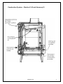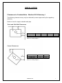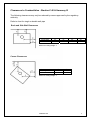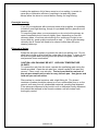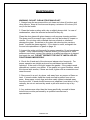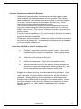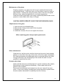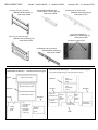
1
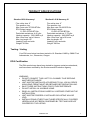
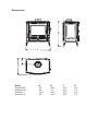
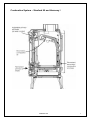
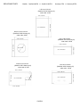
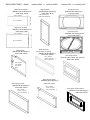
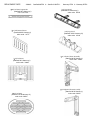
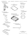
STANFORD 80
STANFORD 140
HARMONY I
HARMONY III
WOOD STOVES
INSTALLATION, OPERATING AND MAINTENANCE INSTRUCTIONS
Manufactured by:
Thermic Distribution Europe SA
5 Rue du Lion
B-5660 Couvin, Belgium
SAVE THESE INSTRUCTIONS FOR FUTURE USE AND REFERENCE
Please read this entire manual before you install and use your new room heater.
Failure to follow instructions may result in property damage or bodily injury.
395823110a
1
SAFETY NOTICE
The authority having jurisdiction (such as municipal building department, fire
department, fire prevention bureau, etc.) should be consulted before installation to
determine the need to obtain a permit.
If your Efel Stove is not properly installed, a house fire may result. For your
safety, follow the installation directions. Contact local building or fire officials
about restrictions and installation requirements in your area.
ENSURE THAT THIS MANUAL REMAINS WITH THE APPLIANCE AND IS
PASSED ON TO THE USER AFTER INSTALLATION.
DO NOT STORE OR USE GASOLINE OR OTHER FLAMMABLE VAPOURS AND
LIQUIDS IN THE VICINITY OF THIS OR ANY OTHER APPLIANCE.
WARNING:
Improper installation, adjustment, alteration, service or maintenance can cause
injury or property damage. Refer to this manual for assistance or consult a
qualified (experienced) installer.
SPECIAL NOTE:
Crazing of Porcelain Enamel:
Porcelain enamel, when heated to high temperature, is subject to crazing. Crazing is
a normal occurrence when enamel is exposed to high temperatures. Your enamel
finish will not be harmed nor will the function of the stove be impaired.
SPECIAL NOTE:
A barometric damper is recommended for installations of stoves in areas that may
have high winds, which can affect the draft. The installation must be only in units
with a newly constructed chimney, free of creosote deposits. The barometric damper
is an automatic device designed to regulate the draft in a heating appliance, which in
turn, stabilizes the chimney temperatures, lessening the potential of over-firing. Do
not place the barometric damper greater than 24 inches (610 mm) above the unit.
Excessive draft will lead to poor control of the burning rate and possible over-firing of
the stove and damage to the cast iron firebox. Most barometric dampers are
calibrated in inches of water column and can be set to draft requirements of -.03 to .08 inches (-7.5 to -20 Pa). It is recommended that the barometric dampers to be set
between -.05 and -.06 inches.
THE RECOMMENDED DRAFT REQUIREMENTS FOR EFEL STOVES IS NO LESS
THAN -.04 AND NO GREATER THAN -.08.
OPERATION OF YOUR STOVE WITH A DRAFT GREATER THAN -.08 CAN
POSSIBLY CAUSE DAMAGE TO THE STOVE AND VOID THE WARRANTY.
395823110a
3
PRODUCT SPECIFICATIONS
Stanford 80 & Harmony I
Stanford 140 & Harmony III
Flue collar size: 6”
Flue position: top
Max. burn rate: 87,000 BTU/hr
EPA Output range:
11,500–55,000 BTU/hr
Particulate emissions: 4.42 g/hr
Heating capacity: 1300-1800 sq ft
Max. burn time: up to 8 hours
Max. log length: 18”
Loading: front and side
Weight: 303 lbs.
Flue collar size: 6”
Flue position: top
Max burn rate: 96,600 BTU/hr
EPA Output range:
12,000–60,900 BTU/hr
Particulate emissions: 2.72 g/hr
Heating capacity: 1800-2500 sq ft
Max. burn time: up to10 hours
Max log length: 22”
Loading: front and side
Weight: 386 lbs.
Testing / Listing
Your Efel wood stove has been tested to UL Standard 1482 by OMNI-Test
Laboratories, Inc., Beaverton, Oregon.
EPA Certification
The Efel wood stoves have been tested to rigorous emissions standards,
and have been certified by the Environmental Protection Agency.
WARNING:
• DO NOT CONNECT THIS UNIT TO A CHIMNEY FLUE SERVING
ANOTHER APPLIANCE.
• UNIT MUST BE INSTALLED ACCORDING TO ALL LOCAL CODES.
A BUILDING PERMIT MUST BE OBTAINED BEFORE INSTALLING.
• SAVE THESE INSTRUCTIONS FOR FUTURE REFERENCE.
• DO NOT INSTALL IN A MOBILE HOME.
• READ ALL INSTRUCTIONS CAREFULLY BEFORE STARTING THE
INSTALLATION.
• UNIT MUST BE PROPERLY INSTALLED OR LISTING WILL BE
VOID.
• INSTALLATIONS OTHER THAN THOSE SPECIFICALLY COVERED
HEREIN HAVE NOT BEEN CONFIRMED BY TEST AND ARE NOT
COVERED BY THE LISTING.
395823110a
4
Dimensions
B
A
D
C
Model
Stanford 80
Stanford 140
Harmony I
Harmony III
A
24"
29"
23¾"
29"
B
28½"
31"
26½"
29½"
C
16½"
20½"
15½"
18½"
D
6½"
7½"
6½"
7½"
Combustion System – Stanford 80 and Harmony I
395823110a
5
Combustion System – Stanford 140 and Harmony III
395823110a
6
INSTALLATION
Clearances to Combustibles - Stanford 80 & Harmony I
The following clearances may only be reduced by means approved by the regulatory
authority.
Refer to chart for single or double wall pipe
Back and Side Wall Clearances
Connector pipe
Single wall
Double wall
A
27.5’’
21.5’’
B
24’’
18’’
C
27’’
27’’
D
18’’
18’’
Minimum Ceiling Height: 7’
Corner Clearances
Connector pipe
Single wall
Double wall
E
19’’
11’’
F
27’’
19’’
Minimum Ceiling Height: 5’
395823110a
7
Clearances to Combustibles - Stanford 140 & Harmony III
The following clearances may only be reduced by means approved by the regulatory
authority.
Refer to chart for single or double wall pipe
Back and Side Wall Clearances
Connector pipe
Single wall
Double wall
A
18’’
14.5’’
B
13’’
10’’
C
32’’
28.5’’
D
20’’
17’’
Minimum Ceiling Height: 7’
Corner Clearances
Connector pipe
Single wall
Double wall
E
16’’
7’’
F
27’’
18’’
Minimum Ceiling Height: 7’
395823110a
8
Standard Installation
1. Position the unit no closer than the minimum clearances to combustible
materials. Check that no overhead cross members in the ceiling or roof will be
cut. Reposition unit if necessary, being careful not to move closer than the
minimum clearances.
2. A non-combustible floor protector (hearth extension) must be installed under
the unit. The floor protector must extend a minimum of 16 inches (450 mm)
beyond the front and side doors and 8 inches (200 mm) beyond the left side.
The floor protector must be equivalent to 1/2 inch (9.5mm) with a k factor of at
least 0.84 Btu/inch°F
Determining Thickness Requirements of Alternate Floor Protection Materials
The following formula gives the means of determining thickness of alternate
materials:
k of the alternate material
k of the specified material
x
thickness of
specified material
=
thickness of
alternate material
For example common brick has a k value of 5.0. The following would
determine the thickness necessary:
5.0
0.84
x
1/2 inch
=
3.0 inches of common brick
3. Mark the position of the required floor protector on the floor. Remove the unit
and install the floor protector.
4. Position the unit on the floor protector at the proper clearances.
5. Install a 6-inch diameter, minimum 24 MSG black or 26 MSG blued steel
connector pipe on the flue collar of the unit.
•
The stove is NOT to be connected to any air distribution duct or system.
•
A chimney connector shall not pass through an attic or roof space,
closet or similar concealed space, or a floor, or ceiling. Where passage
through a wall or partition of combustible construction is desired, the
installation shall conform to CAN/CSA-B365, Installation Code for SolidFuel-Burning Appliances and Equipment. (Canadian installations only )
6. Use a chimney connector adapter to connect the chimney connector up to the
chimney. The small ends of the chimney connector should all point down for a
drip free installation. Position all seams toward the back for aesthetics. The
chimney connector must be 6-inch diameter.
395823110a
9
7. Check that all clearances are still within the allowable tolerances.
8. Secure adjoining sections of chimney connector to each other using three
equally spaced sheet metal screws. Secure the connector pipe to flue collar
using three equally spaced sheet metal screws. DO NOT secure chimney
connector to chimney with screws.
DO NOT CONNECT THIS UNIT TO A CHIMNEY FLUE SERVING ANOTHER
APPLIANCE.
9. The unit must be connected to either:
•
•
a code-approved masonry chimney with a flue liner, or
a 6 inch diameter factory built chimney complying with the requirements
for Type HT chimneys in the standard UL 103.
Minimum Chimney Height
American National Standards Institute ANSI/NFPA 211-92, draft 1-7 states that a
chimney or vent shall be so designed and constructed to develop a flow sufficient
to completely remove all flue and vent gases to the outside atmosphere. The
venting system shall satisfy the draft requirements of the connected appliance in
accordance with the manufactures instructions.
The “3-foot, 2-foot, 10-foot rule” on chimney height states that a chimney must be:
1. at least 3 feet higher than the highest part of the roof opening through which it
passes,
2. and at least 2 feet higher than any part of the roof within 10 feet, measured
horizontally.
2'
10'
3'
395823110a
10
395823110a
11
Freestanding Installations
If the chimney connector must pass through a combustible wall to reach
the chimney, follow the recommendations in the Wall Pass-Through
section that follows.
The opening through the chimney wall to the flue (the “breach”) must be
lined with either a ceramic or metal cylinder, called a “thimble”, which is
securely cemented in place. Most chimney breeches incorporate
thimbles, but the fit must be snug and the joint between the thimble and
the wall must be cemented firmly (Fig. A)
A special piece called the “thimble sleeve”, slightly smaller in diameter
than standard connectors and most thimbles, will facilitate the removal of
the chimney connector system for inspection and cleaning. Thimble
sleeves are available from your local dealer.
To install a thimble sleeve, slide it into the breech until it is flush with the
inner flue wall. Do not extend it into the actual flue passage, as it could
interfere with the draft.
The thimble sleeve should protrude 1-2” (25-50 mm) into the room. Use
fire cement and thin gasketing to seal the sleeve in place in the thimble.
Secure the chimney connector to the outer end of the sleeve with sheet
metal screws.
Above a Fireplace
In this installation, the chimney connector rises from the stove, turns 90°,
and then goes into the fireplace chimney (Fig. B) The liner of the fireplace
chimney should extend at least to the point at which the chimney
connector enters the chimney. Follow all the guidelines for installing a
chimney connector into a freestanding masonry chimney, and pay special
attention to these additional points:
• Double check the connector clearance from the ceiling: 18” minimum.
• The fireplace damper must be closed and sealed to prevent room air
from being drawn up the flue, thereby reducing the draft. However, it
must be possible to re-open the damper to inspect the chimney.
Wall Pass-Throughs
Whenever possible, design your installation so that the wall connector
does not pass through a combustible wall. If you are considering a wall
pass-through in your installation, check with your building inspector before
you begin. Also check with the chimney connector manufacturer for any
specific requirements.
Accessories are available for use as wall pass-throughs. If using one of
these, make sure it has been tested and listed for use as a wall passthrough.
The National Fire Protection Association (NFPA) has established
guidelines for passing chimney connectors through combustible walls.
395823110a
12
Many building code inspectors follow these guidelines when approving
installations.
The methods approved by the NFPA are:
• Cutting away all combustible material in the wall a sufficient distance
from the single wall connector, to provide the required 12” (300 mm)
clearance for the connector. Any material used to close the opening
must be noncombustible (as in Fig . C).
• Using a section of double-wall chimney with a 9” (230 mm) clearance
to combustibles.
• Placing a chimney connector pipe inside a ventilated thimble, this is
then separated from combustibles by 6” (150 mm) of fiberglass
insulating material.
• Placing a chimney connector pipe inside a section of 9” (230 mm)
diameter, solid-insulated factory built chimney, with two inches of air
space between the chimney section and the combustibles.
Chimney
A.
Chimney
connection
connection
is aisfreestanding
a freestanding
installation
installation
Chimney
B.
Chimney
connector
connector
enters
enters
chimney
chimney
above
above
thethe
fireplace
fireplace
AnAn
C.
approved
example
wall
of an
pass-through
approved wall
for the
pass-through
United States
395823110a
13
GUIDELINES FOR SAFE OPERATION
Due to high temperatures, the appliance should be located out of traffic and
away from furniture and draperies.
Advise all adults and especially children to be alert to the hazard of high
temperatures and that they should stay away to avoid burns.
Supervise young children when they are in the same room as the appliance
and/or use a fire guard.
It is imperative that the control compartments and circulating air passageways
of the appliance be kept clean.
The appliance should be inspected before use and the chimney cleaned at
least annually. More frequent cleaning may be required due to poor
operation, installation, or low quality fuel.
CAUTION:
• Hot while in operation. Do not touch. Keep children, clothing and furniture
away. Contact may cause skin burns.
• This room heater is a heat producing appliance and may cause severe
burns if touched. Keep children away.
• All furnishings and other materials should be kept a considerable distance
from the appliance.
• Do not over-fire. If any portion of unit or chimney connector starts to glow,
you are over-firing.
This unit is designed as a radiant room heater and should be used for no other
purpose. Be sure to provide combustion air into the dwelling when using the
appliance. A partially open window or outside air register in the vicinity of the
unit would be acceptable for this purpose.
Unattended Fires
Many structure fires have resulted when a slow burning fire has been left
unattended for an extended period of time. These fires normally occur
because combustible materials close to an appliance become heated to the
ignition point by an over-fired appliance which the operator thought was safely
"throttled down."
Fire intensity is a function of several factors. One of these factors is draft.
Normally, increasing draft increases fire intensity. Conversely, increasing the
fire intensity will increase draft. Draft can also be affected by external factors
such as wind strength and direction, outside temperature, airflow in or out of
the structure, and so forth. If one of these factors changes, the draft of a lowburning appliance may increase. This increased draft may cause dangerously
high temperatures to develop, possibly causing failure of the unit or flue, or
ignition of nearby combustibles. Closing down the combustion air flow
controls may not guarantee that this will not happen.
Exercise extreme caution if a fire must be left unattended
395823110a
14
NOTES ON FIREWOOD
Logs up to 18 inches in length (for Stanford 80 & Harmony I) or 22 inches in
length (for Stanford 140 & Harmony III) allow for better stacking, filling and
operation of your stove.
Use dry wood which by definition must be wood which has been dried under
cover for more than 18 months, in which case the logs contain less than 20%
moisture.
•
•
•
DO NOT USE FUELS OTHER THAN SEASONED WOOD.
NEVER USE GASOLINE, GASOLINE-TYPE LANTERN FUEL,
KEROSENE, CHARCOAL LIGHTER FLUID, OR SIMILAR LIQUIDS TO
START OR “FRESHEN UP” A FIRE IN THIS HEATER. KEEP ALL
SUCH LIQUIDS WELL AWAY FROM THE HEATER WHILE IN USE.
DO NOT BURN TRASH, GARBAGE OR FLAMMABLE FLUIDS SUCH
AS GASOLINE, NAPHTHA OR ENGINE OIL.
Heating the air in a closed building decreases the relative humidity of the air,
which will dry wood and other combustible materials. This drying lowers the
ignition temperature of these materials, thus increasing the fire hazard. To
reduce the risk of fire, some provision should be made for replenishing
moisture to the air whenever a structure is being heated for extended periods.
What is the best wood for the fire?
Some types of wood are easier to light than others.
The best fire wood is always the driest wood.
Using dry wood will minimize creosote build-up.
What are the drawbacks of damp wood?
Damp wood has far less heating power. This lowers the combustion
temperature of the fire, and therefore the output. It is difficult to light, burns
badly and gives off smoke.
Above all the use of damp wood causes the formation of deposits (tarring and
soot staining) in the chimney flue and on the glass door.
Flue gas temperature
The most important aspect of stove operation is maintaining a high
combustion temperature. If the combustion of the fuel is at the correct
temperature, most of the soot and tars (hydrocarbons) are burned. These
hydrocarbons, when not burned, can be seen as tar and creosote deposits on
the internal surfaces of the stove, glass and chimney surfaces. To assist in
maintaining these temperatures, a surface mounted stove thermometer is
recommended.
High combustion temperatures are the secret to clean glass operation. When
loading wood, add one or two logs at a time, depending on size. Loading the
395823110a
15
appliance full of damp wood on a low fire is certain to cause poor combustion
efficiency, resulting in tar and dirty glass.
It is recommended that you heat your stove to at least 400°F before reducing
the air controls. This procedure should always be carried out after reloading.
Storage time for wood
Wood supplied in ready-cut lengths stored immediately under a ventilated
shelter dries quicker than wood stocked in high piles. Quarters (split wood)
dry quicker than round logs. Wood which is too small to split must be drained,
by removing some of the bark. Round logs left in the open for more than a
year end up rotten. The drying time for the fire wood must be at least 18
months to 2 years. This period can be shortened (12 to 15 months) if the wood
is cut to the right length and immediately stored under a ventilated shelter.
395823110a
16
OPERATING INSTRUCTIONS
Air intake controls
Primary Air Control
The Primary Air Control allows you to adjust the rate of burn. Sliding the lever to
the left decreases air intake, thus increasing the burn time. Sliding the lever to
the right increases air intake, resulting in higher flames and a cleaner burn.
Adjustable Primary Air Control
(All Models)
Start-up Air Control
Additional air for start-up can be supplied from the ignition booster air control,
located on the back right corner of the Stanford 140 and Harmony III models.
This can be especially helpful when your chimney is cold. Sliding the lever to the
right increases air for start-up. Five minutes after lighting the fire, close the
ignition booster air supply by sliding fully to the left. Do not operate the stove for
long periods of time with the ignition booster open.
Start-up Air Control for Ignition Booster
(Stanford 140 and Harmony III only)
395823110a
17
Starting a Fire
1.
2.
Fully open the primary air control.
Place a small amount of paper in the firebox and cover with a few pieces of
kindling.
Light the paper in the stove.
Once the kindling is burning quickly, add several pieces of wood. Be
careful not to smother the fire. For best results, use smaller pieces of wood
to get the stove temperature high before loading larger wood for sustained
burns.
Load logs evenly across the base being cautious not to place wood in front
of the rear edge of the log guard.
Close the loading door.
With the primary air control open to its maximum, open the stove door a
fraction and burn for 5 minutes. Then close the stove door. Never leave the
stove unattended when the door is open.
Adjust the primary air control depending on the temperature of the stove
required.
3.
4.
5.
6.
7.
8.
Reloading the Stove
To prevent smoke blowing into the room follow these recommendations:
1.
Open the primary air control to allow fire to recover for a few minutes.
2.
Close the primary air control and open the loading door.
3.
Rake the embers towards the front of the stove and spread evenly. If there
are logs only partially burned rake these to the front of stove.
4.
5.
6.
7.
-
-
Feed the logs to the embers. Try to use side loading door as it will allow for
cleaner operation. Load logs evenly across the base being cautious not to
place wood in front of the rear edge of the log guard.
Close the loading door.
Open the primary air control to its maximum, open the stove door a fraction
and burn for 5 minutes. Then close the stove door. Never leave the stove
unattended when the door is open.
Adjust the primary air control depending on the temperature of the stove
required.
In order to maintain an attractively burning fire, logs should be up to 18"
long (Stanford 80 and Harmony I) or 22” long (Stanford 140 and Harmony
III) and well seasoned.
High combustion temperatures are the secret to clean glass operation.
When loading wood add one or two logs at a time, depending on size.
395823710a
18
Loading the appliance full of damp wood on a low setting, is certain to
cause poor combustion efficiency resulting in tar and dirty glass.
Always allow the stove to recover before closing for long burning.
Overnight burning
If you fill your appliance with wood and close all air supplies, it is possible
to achieve overnight burning, though it is probable that the glass door will
become dirty.
To keep the glass clean, we recommend you do not shut the primary air
control completely but to leave it slightly open, depending on how the
chimney draws, to achieve slow burning for a maximum of eight to ten
hours (with dry, good quality wood such as oak…). With a good drawing
chimney the air control will need to be closed further than with poor
drawing chimneys.
Disposal of Ashes
Empty the ash pan regularly to prevent the ash from spilling over. Do not
allow ash to build up and touch the under side of the grate. A layer of ash
left over the grate when burning wood will protect the grate, retain heat,
and promote clean combustion.
CAUTION: ASH PAN MAY BE HOT. USE HIGH TEMPERATURE
GLOVES.
To remove the ash from the stove, operate the oscillating grate using the
handle provided. Open the ash pan door, attach handle to ash pan and
remove. Place cover over ash pan. The tool provided for removal of
the ash pan should not be used to carry the ash pan. Use gloves and
hold ash pan on both sides.
Place ashes in a metal container with a tight fitting lid. The closed
container of ashes should be placed on a non-combustible floor or on the
ground, well away from all combustible materials, pending final disposal.
If the ashes are disposed of by burial in soil or otherwise locally dispersed,
they should be retained in the closed container until all cinders have
thoroughly cooled.
395823110a
19
MAINTENANCE
WARNING: DO NOT CLEAN STOVE WHILE HOT.
1. Always keep the area around the unit clean and clear of furniture and
other objects. Keep all furniture and drapery a minimum 36 inches (914
mm) from the heater.
2. Clean the heater surface with a dry or slightly damp cloth. In case of
condensation, clean the affected areas before they dry.
Clean the door glass with glass cleaner or all-purpose cleaning solution.
The glass used is a ceramic type, which can only be broken by impact or
misuse. Do not clean with materials that may scratch or otherwise
damage the glass. Scratches on the glass can develop into cracks or
break. Inspect the glass regularly. If you detect a crack, extinguish the
fire and see replacement of glass on page 16.
3. Inspect the entire unit frequently for proper operation, fit and soundness
of parts. If any malfunctioning, cracked, broken, or loose parts or other
problems are noted, contact your dealer or qualified serviceman to inspect
and repair the unit. DO NOT OPERATE THE UNIT IF INSTALLED OR
FUNCTIONING IMPROPERLY.
4. Check the fit and seal of the doors and ashpan door frequently. For
proper operation an airtight seal must be maintained around these
openings. If the seal is not tight, inspect the gasket. If the gasket needs
replacement, contact your dealer. If the gasket is in good condition, check
the closure latch screws; if these are loose, tighten with a screwdriver and
retest the seal.
5. Store wood in a cool, dry place, well away from any source of flame or
heat. If stored outside, keep the wood covered to protect from rain or
snow. Keep paper, wood, rags and other easily ignited materials away
from the wood. If wood should become wet, separate it and allow it to dry
naturally; do not mix wet and dry wood or pile wet wood on top of dry
wood.
6. Any maintenance other than the items specifically covered in these
instructions must be performed by a qualified manufacturer's
representative.
395823110a
20
Creosote Formation and Need for Removal.
When wood is burned slowly, it produces tar and other organic vapors,
which combine with expelled moisture to form creosote. The creosote
vapors condense in the relatively cool chimney flue of a slow burning fire.
As a result, creosote residue accumulates on the flue lining. When
ignited, this creosote makes an extremely hot fire.
The chimney connector and chimney should be inspected at least once
every two months during the heating season to determine if a creosote
build-up has occurred. The chimney connector must be in good condition
and kept clean.
If creosote has accumulated (1/8 “(3 mm) or more) it should be removed to
reduce the risk of a chimney fire. Experienced chimney servicing
personnel should be consulted.
Contact your local municipal fire authority for further information on what to
do in case of a chimney fire. It is extremely important to have a clear plan
on how to handle a chimney fire.
Procedure to follow in case of a chimney fire:
A.
Prepare to evacuate to ensure everyone’s safety. Have a wellunderstood plan of action for evacuation. Have a place outside
where everyone is to meet.
B.
Close all the air controls on the stove.
C.
Call the fire department. Have a fire extinguisher handy.
D.
After the chimney fire is out, the chimney must be cleaned and
checked for stress and cracks before starting another fire. Also
check combustibles around the chimney and the roof.
Establish a routine for the fuel, wood burner and firing technique. Check
daily for creosote build-up until experience shows how often you need to
clean to be safe. Be aware that the hotter the fire, the less creosote is
deposited. Weekly cleaning may be necessary in mild weather even
though monthly cleaning may be enough in the coldest months. Contact
your local municipal or provincial fire authority for information on how to
handle a chimney fire. Have a clearly understood plan to handle a
chimney fire.
395823110a
21
Maintenance of the glass
Properly operated, your glass door will not get coated with thick tar like
conventional stoves. If this does occur you may have to resort to using a
glass cleaner. However by using dry wood, much of the tar on the glass
will burn clean, when the appliance is run at high temperature.
Clean the ceramic glass when cold using commercial products sold for this
purpose, or warm water with a drop of vinegar.
CAUTION: NEVER OPERATE YOUR STOVE WITH BROKEN GLASS.
Replacement of the glass
1.
2.
3.
4.
Open the door as indicated below.
Remove the 4 fixing screws and fit the new glass.
Replace the seals.
Install the 4 screws. Do not over-tighten the screws.
When replacing glass always replace glass seals.
Other maintenance
Clean the unit, the flue outlet, and the chimney at the end of each heating
season or more often if the use of the stove, or the fuel make it necessary.
For cleaning purposes the baffle plates can be removed without any tools.
This gives access to the cleaning flap of the smoke flue and it is even
possible to reach the flue outlet.
Summer shut down
Ashes shall be removed, and disposed of in a steel container with a tightly
fitting lid and moved outdoors immediately. Other waste shall not be
placed in this container.
Remove all remaining ash and cinders from the unit, close all the stove
doors. If the room is damp, possibly place some absorbent crystals inside
the stove and/or disconnect it completely from the chimney.
395823110a
22
REPLACEMENT PARTS
- Models: Stanford 80 EPA & Stanford 140 EPA -
Harmony I EPA & Harmony III EPA
Left Lower Firebrick
(Stanford 140 & Harmony III)
order code: 41201
.79” / 20 mm thick
Bottom Center Firebrick
(Stanford 140 & Harmony III)
order code: 41287
10. 08” / 256mm
7.87” / 200 mm
Upper Left Firebrick
(Stanford 140 & Harmony III)
order code: 41202
7.87” x 200 mm
4.6” / 117 mm
.79” / 20 mm thick
Bottom Side Firebrick
(Stanford 140 & Harmony III)
order code: 41198
5. 51” / 140 mm
9 . 2 5 ´/ 2 3 5 m m
10.43” / 265 mm
Lower Rear Firebrick
(Stanford 140 & Harmony III)
order code: 41204
12.36” / 314 mm
.79” / 20 mm thick
.79” / 20 mm thick
2.87” / 73 mm
9.25” / 235 mm
PAGE 23
7. 87” x 200 mm
7. 87” / 200 mm
13.94” / 354 mm
REPLACEMENT PARTS - Models:
Stanford 80 EPA & Stanford 140 EPA -
Right Lower Firebrick
(Stanford 140 & Harmony III)
order code: 41203
4. 72” / 120 mm
10.43” / 265 mm
.79” / 20 mm thick
Right Firebrick
(Stanford 80 & Harmony I)
order code: 38741
Fuel Grate Frame
(Stanford 80 & Harmony I)
order code: 30863
8.47” / 215 mm x 5.12” /
130mm (.98” / 25mm thick)
Upper Rear Firebrick
(Stanford 140 & Harmony III)
order code: 41205
Fuel Grate Frame
(Stanford 140 & Harmony III)
order code: 38270
7. 87” / 200 mm
13.93” / 354 mm
.79” / 20 mm thick
Harmony I EPA & Harmony III EPA
Left Firebrick
(Stanford 80 & Harmony I)
order code: 38742
Baffle Firebrick
(above tubes on ceiling)
(Stanford 80 & Harmony I)
order code: 38745
5.87” / 149 mm
x 14.36” / 365 mm
(.98” / 25 mm thick
Air Column Gasket
(Stan 80, Harm I,Stan 140, Harm III)
order code: 40264
)
8.47” / 215 mm
x 12” / 305 mm
(.79” / 20mm
thick)
Lower Rear Firebrick
(Stanford 80 & Harmony I)
order code: 38743
6.50” / 165mm
x 12.40” / 315 mm
(.98” / 25 mm thick
)
Upper Rear Firebrick
(Stanford 80 & Harmony I)
order code: 38744
5.51” / 140mm
x 12.60” / 320 mm
(.98” / 25 mm thick
)
Start-up Air Column Gasket
(Stanford 140 & Harmony III)
order code: 40739
REPLACEMENT PARTS
- Models:
( ♦20) Fuel Grate Support Bar
(Stanford 80 & Harmony I)
order code: 32045
( ♦21) Ash Removal Grate
(Stanford 80 & Harmony I)
order code: 19777
( ♦22) Fuel Grate
(Stanford 80 & Harmony I)
order code: 39449
( ♦23) Fuel Grate
(Stanford 140 & Harmony III)
order code: 38262
Stanford 80 EPA & Stanford 140 EPA -
Harmony I EPA & Harmony III EPA
( ♦29) Log Guard
(Stanford 80 & Harmony I)
order code: 20220
( ♦30) Log Guard
(Stanford 140 & Harmony III)
order code: 41546
( ♦31) Left Air Column Assembly
(Stanford 80 & Harmony I)
order code: 39455
( ♦31) Right Air Column Assembly
(Stanford 80 & Harmony I)
order code: 39454
REPLACEMENT PARTS
- Models:
Stanford 80 EPA & Stanford 140 EPA -
Left Air Column Assembly
(Stanford 140 & Harmony III)
order code: 40706
Ashpan
(St 80, Harm I, St140, Harm III)
order code: 41526
Harmony I EPA & Harmony III EPA
Flue Outlet Collar
(Stanford 80 & Harmony I)
order code: 39443
Flue Outlet Collar
(Stanford 140 & Harmony III)
order code: 21332
Right Air Column Assembly
(Stanford 140 & Harmony III)
order code: 40715
Side View
Baffle Assembly, Ceramic Fiber
Brick (above secondary air tubes)
(Stanford 140 & Harmony III)
order code: 41540
Top View
Upper Air Deflector
(Stanford 80 & Harmony I)
oreder code: 45135
Start-up Air Channel Assembly
(Stanford 140 & Harmony III)
order code: 41530
Upper Air Deflector
(Stanford 140 & Harmony III)
order code: 41298
Fire Poker
(St 80, Harm I, St140, Harm III)
order code: 20017
REPLACEMENT PARTS
- Models: Stanford 80 EPA & Stanford 140 EPA Air Control/Ash Pan Removal Tool
(St 80, Harm I, St140, Harm III)
order code: 20034
Secondary Air Tube Assembly
(Stanford 80 & Harmony I)
order code: 39492
Harmony I EPA & Harmony III EPA
Draft Module (Air Intake Slide)
(Stanford 140 & Harmony III)
order code: 41720
Rear Firebrick Retainers
(Stanford 140 & Harmony III)
order code: 41852
Secondary Air Tube Assembly
(Stanford 140 & Harmony III)
order code: 40700
Side Retainers Not Shown
Draft Module (Air Intake Slide)
(Stanford 80 & Harmony I)
order code: 33880
Stanford 80 & Harmony I
Firebrick Placement Diagram
Stanford 140 & Harmony III
Firebrick Placement Diagram
Note: The refractory baffle assembly on ceiling (above tubes), not shown.
CEILING
BACK WALL
Baffle Firebrick, 38745
Upper Rear Firebrick, 38744
RIGHT WALL
Left Side
Firebrick
38742
Note:
St. 80 & Harm I do
not have firebrick on firebox floor (fuel
grate & frame
on floor only).
Lower
Rear Firebrick
41204
LEFT WALL
Lower Rear Firebrick, 38743
LEFT WALL
Upper
Rear Firebrick
41205
BACK WALL
Upper Left
Firebrick 41202
Lower Left
Firebrick 41201
Right Side
Firebrick
38741
RIGHT WALL
Bottom
Side
Firebrick
41198
Bottom
Side
Firebrick
41198
Bottom Center
Firebrick, 41287
FLOOR
Lower Right
Firebrick, 41203