1
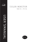
X Lite MK1
UHF Radio Paging System
Model XLUK
Installation & User Manual
XLite
Scope Marketing (Communications UK) Ltd, The Scope Complex, Wills Rd, Totnes, Devon TQ9 5XN
Tel: +44 1803 864569 Fax: +44 1803 863716
XLITE/1
Scope Xlite USA Version
PREFACE
Important Installation Information
It is the purchasers’ responsibility to determine the suitability of this equipment and its derivatives for any
given application, Scope cannot give specific advice in this manual, as each use will require independent
evaluation.
Scope has, wherever possible, employed extra safeguards or designed optional equipment to further
monitor the system’s performance. Certain system installations, operational requirements or budgets
may, however, limit the effectiveness of these safeguards. Again, the suitability of the system for any
given application must therefore be decided by the installer and their customer, relative to the application
and risk.
Licence
This equipment is cleared for use within the USA under a license assigned to the exclusive importer,
PIPS Holdings Inc. License No. 950415906. Certain restrictions apply in respect of power output and
antenna installations.
Alternative frequencies are available by formal license application (Form 600) via the FCC. These will not
be subject to the same restrictions as the standard assigned license. You should obtain the FCC Rules
and Regulations, Title 47, Part 80 to End, including Parts 90 and 95, available from the US Gov. Printing
Office, GPO Bookstore, FCC Office or www.fcc.gov/oet/info/rules/
Important Safety Information
Scope products are designed to operate safely when installed and used according to general safety
practices. The following requirements should be observed at all times.
Do NOT subject this equipment to:
Mechanical shock
Excessive humidity or moisture
Extremes of temperature
Corrosive liquids
This equipment is designed for indoor use, unless expressly stated otherwise, and must not be used in
classified Hazardous Areas, including areas containing explosive or flammable vapors, unless express
authorization has been given in writing by the manufacturer. If in doubt, consult your local product dealer
for further information.
Do not obstruct any slots or openings in the product. These are provided for ventilation to ensure reliable
operation of the product and to protect it from overheating.
Only use a damp cloth for cleaning (not liquid or aerosol based cleaners), and ensure that any power is
removed from the unit prior to beginning the cleaning operation.
Removal of covers from the equipment must only be undertaken by authorized service personnel, who
must ensure that power is isolated prior to removal.
XliteUSA 01/00
Issue 1
1
Scope Xlite USA Version
PREFACE
Equipment Applications
It is the user’s responsibility to determine the suitability of the Scope products for any given application.
Scope, including its subsidiaries and Distributors, cannot provide specific advice within this manual, as
each application will require independent evaluation. Common sense dictates that certain applications
may require back up systems to cover in the event of mains or equipment failure. All applications should
be thoroughly assessed by the installer in conjunction with the customer so as to minimize risk. Scope
has no control of the use and application of the frequencies issued by the FCC. Some equipment that is
individually licensed may have a greater degree of protection than other equipment that is operated on a
FCC License Assignment basis. The following information, however, may be of benefit.
Equipment Testing.
Range tests should be carried out at least once a week on portable radio equipment, more often when
critical criteria apply. This should involve testing the unit past the limit of its required working range. Good
working practice dictates that a suitable system installation log, covering both portable and fixed
equipment must be generated, together with a record of the dates when the system has been manually
checked and/or serviced, (with the aid of suitable test equipment etc.) enabling the system performance
to be compared with the original installation data.
The frequency of the tests required will vary between applications. If portable equipment has been
dropped or is worn by a person involved in an accident, the unit should be tested again before re-use. It
must be stressed that the physical range tests are essential and that any construction work or movement
of plant or equipment could alter the signaling capability of the unit. Radio equipment, like any other
requires servicing from time to time to ensure that it is operating to its optimum performance. It is
therefore essential that equipment is inspected and tested by authorized service centers at least once a
year.
Literature
Scope Marketing (Communications UK) Ltd, the manufacturer, in conjunction with it’s distributors
operates a policy of continual improvement, and therefore reserve the right to modify or change any
specifications without prior notice.
While every possible care has been taken in the preparation of this manual, Scope does not accept any
liability for technical or typographical errors or omissions contained herein, nor for incidental or
consequential damage arising from the use of this material.
Installation
Installation must only be undertaken by an Approved contractor, who shall ensure that all work is carried
out in compliance with the appropriate State and Federal Regulations. For mains powered equipment, a
readily accessible isolating fuse or socket must be located within 1 meter of the equipment.
Liability
Scope does not accept liability for any damage or injury, howsoever caused as the result of misuse of this
equipment. It is the responsibility of the user to ensure that the equipment is operated in the manner for
which it was intended and that it is the correct item of equipment for the required task.
XliteUSA 01/00
Issue 1
2
Scope Xlite USA Version
PREFACE
Warranty
This product is warranted as free from defects of workmanship and materials for a period of one year from
the original purchase date. During this time, if there is a defect or malfunction of this product, Scope will,
with proof of purchase, repair or replace at its discretion any defective parts, free of charge. This does not
include where the adjustments, parts and repair are necessary due to circumstances beyond the control
of Scope, including but not limited to fire or other casualty, accident, neglect, abuse, abnormal use or
battery leakage damage.
There are no other expressed or implied warranties except as stated herein, and those excluded include
those of merchantability and fitness for a particular purpose. In no event will Scope or any of its agents be
liable for direct, indirect, special incidental or consequential damages resulting from any defect in the
product, even if advised of the possibility of such damages.
The warranties and remedies set forth above are exclusive and in lieu of all others, oral or written,
expressed or implied. No Scope distributor, dealer, agent or employee is authorized to make any
modification, extension or addition to this warranty.
Some states do not allow limitations on how long an implied warranty may last and some states do not
allow exclusions or limitation of incidental or consequential damages.
Warning ! No User Serviceable Parts
Alteration or modification to any part of this equipment, without the prior written consent of the
manufacturer, will invalidate all manufacturer approvals and warranties. No adjustments can be
undertaken except by qualified and licensed persons as defined by the FCC Rules and Regulations.
Operation of altered equipment can result in fines, imprisonment, and/or confiscation of such equipment.
© Scope Marketing (Communications UK) Ltd, 2000 All Rights Reserved
XliteUSA 01/00
Issue 1
3
Scope Xlite USA Version
System Overview
The Scope Xlite is a POCSAG budget entry point data display radio paging system which can be used to
transmit alphanumeric\ text messages direct to pocket pagers carried by individuals or entire groups.
Information is input by way of an RS232 serial port. Up to 9,999 pagers can be supported on any one
system.
Base Equipment type & description:
Xlite Single Port Paging Transmitter
Transmitter FCC ID:
JRNUSASERILINK
Transmitting Frequency:
457.550 MHz or 457.575 MHz*
Effective Range:
Up to 1 mile with standard aerial!
* or as specified on separate configuration sheet
!optional external aerials and amplifiers available for greater range
Section 1: Installation
The information contained in this Section is intended for use by authorized system installation
engineers only. Unqualified personnel should not undertake installation of this equipment under
any circumstances whatsoever.
Location of the hardware
Before locating the hardware in any given location, it is important to take into account the range of
operation that you require to obtain from your system. The standard transmitter can quite easily provide
ranges of up to a mile or more and will provide excellent propagation on most industrial sites, covering a
considerable area with just a quarter wave antenna (BNC terminated) connected directly to the unit.
For coverage of very large sites, or where exceptionally difficult operating conditions exist, it may be
advantageous to install an external antenna. Installing the transmitter on the second or third floor of a
building will more often than not boost overall range. However, horizontal range is not always required as
much as propagation through a multi story building. Here it may be more useful to use a small external
antenna mounted outside the building at half the building height. Sometimes range is required more in
one direction than in the other: moving the aerial to one side of the building can provide a bias in the
required direction, which may overcome the range difficulties. (See section: Other Antennas).
Important: coaxial feeds which are longer than 5 meters must employ low loss 50 ohm coax. We normally
do not recommend feeds of more than 15 meters for standard applications. However, we suggest you
contact our technical department where other considerations may prove this to be impractical.
A further consideration that must be taken into account is the distance between the transmitter and the
source of the data feeding the transmitter. If the unit is to deploy a standard RS232 serial interface,
reliable reception of the data should not be attempted in excess of 15 meters of cable. These cables
should be screened/shielded and must be kept clear of sources of induced magnetic or electrical noise. In
the event that distances of over 15 meters are required for the data feed, additional drivers or amplifiers
must be installed at both ends of the data link.
XliteUSA 01/00
Issue 1
4
Scope Xlite USA Version
Some major points to consider when installing equipment:
1
Never install antennas near or adjacent to telephone, public address or data
communication lines or overhead power cables.
2
Avoid, where ever possible, running antenna coax alongside other cables.
3
Avoid mounting the transmitter in the immediate vicinity of telephone exchanges
or computer equipment.
4
Always use proprietary 50 ohm coaxial cable between the antenna and the
transmitter. If cable runs exceed 5 meters, always use low loss 50 ohm cable
such as RG213, UR67 or equivalent.
Coaxial cable intended for TV, Satellite or CCTV installations is normally 75 OHM
and therefore totally unsuitable for any transmitter installation manufactured by
Scope.
5
Also remember that the performance of the system will be affected by the type of
material the unit is mounted on and its surroundings.
The following is a list of materials that this transmitter will be adversely affected
by if mounted on or if mounted in close proximity to:
a)
b)
c)
d)
Foil back wallboard
Metal mesh or wire reinforced glass
Metal sheeting, large mirrors or suspended ceilings
Lift shafts
All of the above can reflect radio waves and thereby reduce the capability of the
transmitter to perform its desired functions.
6
The circuit boards within this equipment may be harmed by Electrostatic
Discharge (ESD). Installers should avoid touching the circuitry wherever
possible, and should ensure that adequate anti-static procedures are adhered to
at all times (earth bonding with wrist straps, etc).
7
Warning! Never transmit without an aerial attached to the transmitter
8
Warning! Carefully check the Installation section in this manual covering data pin
connections prior to installation. Damage caused by incorrect connection is the
responsibility of the installer!
XliteUSA 01/00
Issue 1
5
Scope Xlite USA Version
Installation
The following procedure must be adhered to when installing the Xlite paging system. Ensure you have
taken into consideration all of the above information before selecting the location for your transmitter. If in
doubt, contact your dealer for further advice.
1
Remove the cover from the Xlite transmitter unit by undoing the two Pozi head screws located on
the front of the unit (see Diagram 1).
2
Carefully lift off the cover and set aside.
3
The transmitter should be fixed to a flat wall surface using suitable screws fitted through the holes
provided in the chassis plate. Hold the chassis up to the chosen location and with the aid of a
pencil mark the position of the mounting holes.
Warning: Do not use the chassis plate as a template for drilling the holes into the wall. Hammer drills
vibrating through the chassis may irreparably damage the quartz crystals on the printed circuit boards.
4
Place the Xlite transmitter over the mounting holes and secure the unit with suitable screws.
5
Connect the antenna to the unit via the BNC connector located at the top of the housing. If the
antenna is an external antenna, or an antenna which is separate from the transmitter unit itself,
ensure that the previous criteria covered under the section headed Location of the Hardware,
have been strictly adhered to (also see section headed Other Antennas).
SERIAL PORT (25 way D Type Plug)
9PIN
TO
03
02
08
07
05
--04
25PIN
02
03
04
05
07
19
20
SIGNAL
DIRECTION
TRANSMIT DATA
(TX) OUT
RECEIVE DATA
(RX) IN
REQUEST TO SEND
(RTS) OUT
CLEAR TO SEND
(CTS) IN
GROUND
(GND)
+5V
(for Scope peripherals)
DATA TERMINAL READY (DTR) OUT
As information passes only from the host equipment to the Xlite transcoder, you will only need to read the
DTR line which, if high at the port pin, shows that power is applied to the Xlite unit. The RTS line will be
high when the transcoder ‘s ready to receive data. The Xlite RTS line should be connected to the host
CTS line to facilitate correct handshaking. Prior to connecting the data cable, thoroughly check the
system pin connections as shown above.
6
Replace the cover and re-fit the two retaining screws.
7
Power can be provided by way of an AC adapter (part no PTPS12110V, not supplied), or from the
host system (if suitably equipped) with a12-13.8 volts dc supply, @ 300 mA max. With power
applied, the red LED on the front cover of the unit should be lit.
8
The system is now ready to accept calls from the host terminal. When a call is transmitted, the
green LED on the front cover of the unit will light momentarily.
XliteUSA 01/00
Issue 1
6
Scope Xlite USA Version
X Lite
XliteUSA 01/00
Issue 1
7
Scope Xlite USA Version
Section 2: System Operation
In addition to the Scope default protocol, the Xlite can be ordered with a number of industry standard
protocols. Please check before ordering a unit for any specific application and always confirm the port
configuration, e.g. N,8,1. The system will auto detect baud rate from 600 to 9600.
Sending data in the correct format (see Technical Section, Calling Pagers) will invoke transmitted
messages to the relevant pagers.
Problems and Fault Finding.
1
Check and re-check the data cable connections. This, together with an incorrect signaling
format, result in more faults than any other problem.
2
Check that the communications configuration and protocol on the host matches the system
(e.g. 8,N,1, Scope). Note: auto baud rate detection is from 600 to 9600 baud.
3
Check that the pagers are at least 3 meters from the transmitter and aerial. Under certain
conditions it is possible to flood the pager receivers and corrupt the data received.
4
Check that the pagers have the battery installed with the correct polarity and are correctly
powered up.
5
Check that the red power LED on the front of the transcoder is lit. If not, check the power
hook up with the aid of a suitable meter.
6
Check that the green LED lights for the duration of the transmission. If not, go back to the
data cabling and re-check the signal format.
7
Check that the aerial is correctly installed.
8
Check the pagers are set to alphanumeric 1200 baud and are resident on the correct radio
frequency.
*****************************************************
XliteUSA 01/00
Issue 1
8
Scope Xlite USA Version
Other Antennas
The range and performance of this equipment can be improved by the addition of more efficient
antennas*. Aerial efficiency and choice of aerial location will have far more effect on range and
signaling integrity than deploying a power amplifier. These can be installed either inside or
outside the building and are connected to the transmitter with 50 OHM coaxial cable.
Glass mount antenna (UHFGM): for installation on the inside of a suitable window. This can boost
range, especially if it is required in one direction from the building.
The center fed half wave dipole, measuring approximately 12 inches from tip to tip, will provide
excellent all round local signaling. This can be mounted either inside or outside a building. Two
versions are available:
1) a light duty antenna suitable for sheltered environments/internal installation (LUHFDP).
2) a heavy duty stainless unit with optional mounting hardware for more arduous applications
(UHFDP).
Other antennas, including collinear, are available for external applications. Consult your dealer for
further details.
Pre-terminated coaxial feeder cables are available for 5, 10 or 15 meter requirements.
Note ! High frequencies can equate to high power losses. Always use quality cable. RG58 is only
acceptable on cable runs of up to 5 meters. We recommend RG213, or equivalent, on greater
lengths. If in doubt consult your dealer.
*subject to license conditions. Specifically, mounting height and Effective Radiated Power (ERP).
Consult your dealer before changing antenna type.
Service Information
If you experience a problem with your equipment, please contact the distributor from whom it was
purchased. In any event, ensure you have the systems details at hand for reference purposes.
Record your system details here for quick reference:Date supplied____/____/____
Supplied by (dealer):____________________________
*Serial Number: ___ ___ ___ ___ ___ ___ ___
* 7 digit number located on the rear chassis plate of the Xlite unit (see Diagram 1)
Transmitter frequency __ __ __
. __ __ __MHz
FCC ID No: JRNUSASERILINK
System base ID number__________________
Serial port configuration ________________ (e.g. 8,N,1)
Serial port protocol____________________ (e.g. SCOPE, COMP1, COMP2, TAP)
Alphanumeric Pager Ranges:
from______________ to ______________
For information on individual pager types, refer to the appropriate pager manual
XliteUSA 01/00
Issue 1
9
Scope Xlite USA Version
System Specification
Voltage Input:
12 to 13.8 volts
Power Consumption:
300 mA max
System Power Consumption:
less than 50mA standby, 300mA (transmit)
Transmitter:
Frequency Range:
450-470 MHz
Channel Spacing:
25 KHz
TX Baud Rate:
1200
FCC ID No:
JRNUSASERILINK
Serial Port:
Baud Rate:
Auto detect from 600 to 9600
Port configuration:
8,N,1 (default)
Protocol:
Scope (default)
General:
Footprint (mm):
!185 (H) x 140 (W) x 42 (D)
*dependent on system configuration
!excluding aerial
Scope’s policy is one of continuous development and specifications are subject to change without notice
XliteUSA 01/00
Issue 1
10
Scope Xlite USA Version
Section 3: Technical Information
This section provides a more in depth understanding of how messages are formatted for serial
communication from a host. It provides useful information for hook up to serial data devices or for
programming pagers and understanding the system configuration. Depending upon the issue of
software resident in the controller the message length will be a maximum of either 512 or 2000
characters. Check before quoting or ordering.
Calling Pagers
Pagers all use 7 digit numeric addresses which enables the system to support thousands of
pagers without identity clashes. Most pagers will support multiple addresses (sometimes referred
to as CAP codes, RIC’s or identities ID’s). This enables the pager not only to respond to its own
unique address but also to respond to group or global addresses.
These real 7 digit numeric codes are often substituted for shorter logical numbers which are
easier to remember and more meaningful. It also allows, in most cases logical pager numbers to
be generated to match the customers internal telephone extension numbers. Under these
conditions the host or specialty program within the transcoder will perform an algorithm on the
data string received to convert the simpler logical number back into a real 7 digit number for
transmission.
The real 7 digit pager numbers are always spaced 8 digits apart. This is a function of the
POCSAG standard, it allows for eight frames in which the pager identity can reside. Scope uses
frame 0 as a default for most systems as this provides for the fastest pager response when
called.
To avoid system identity clashes, transcoders are provided with a base number within the range
of 1000 to 1,999,000. If for example a base address of 0100,000 is applied to a transcoder, the
first real pager number will 0100,008 followed by 0100,016 and so on.
Logical pager numbers are normally used on systems fitted with the telephone interface and
those which are interfaced to personal computers. The algorithm would perform the following
function:For example take the logical pager number of 123
The logical pager number 123 will be multiplied by 8 and then added to the base number to
provide the 7digit real number
Logical No
123
Base No
x
8
=
984
+
0100,000
Real No
=
0100984
Pager address 1, or ID 1 is normally reserved as the personal identity for that specific pager.
Other addresses, of which there can be 6 or more, can be tagged to specific pagers to form
selected groups. Address 2 or ID 2 could, for example, be used for all pagers to formulate a
global call.
Address codes can be divided between full addresses and sub addresses. Full addresses can
allow four different bleep types, A, B, C or D, whereas sub-addresses will only accommodate a
fixed bleep type. A status line of information will normally be provided on the pager screen which
will highlight the type of bleep sent together with other status information.
XliteUSA 01/00
Issue 1
11