1
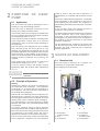
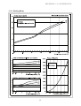
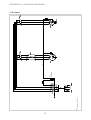
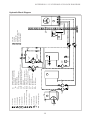
CE
MOUNTING and OPERATING MANUAL
Reversible Air-to-Water Heat Pump
for Outdoor Installation
LA 16ASR
Order No.: 452158.66.21
FD 8507
CONTENTS
1
READ IMMEDIATELY
3
1.1
1.2
1.3
Important Information
Legal Provisions and Guidelines
Energy-Efficient Use of Heat Pumps
2
PURPOSE OF HEAT PUMP
2.1
2.2
Application
Principle of Operation
3
SCOPE OF DELIVERY
3.1
3.2
3.3
Baseline Unit
Control Box
Heat Pump Controller
4
TRANSPORT
5
5
INSTALLATION
6
5.1
5.2
General
Condensate Line
6
MOUNTING
6.1
6.2
6.3
General
Heating and Hot Water Connection
Electrical Connection
7
COMMISSIONING
7.1
7.2
7.3
7.4
General
Preparation
Procedure During Heating Period
Procedure During Cooling Period
8
CLEANING / MAINTENANCE
8.1
8.2
8.3
Maintenance
Cleaning of Heating Side
Cleaning of Air Side
9
MALFUNCTIONS, TROUBLESHOOTING
9
10
DECOMMISSIONING
9
10.1
10.2
Placing Out of Service in Summer
End-of-Life Decommissioning / Disposal
11
APPENDIX
4
4/5
6/7
7/8
8/9
FF
2
READ IMMEDIATELY
1
READ IMMEDIATELY
1.2 Legal Provisions and Guidelines
1.1 Important Information
This heat pump was designed and built in
compliance with all relevant EU directives, DIN and
VDE regulations (see CE Declaration of Conformity).
CAUTION!
The electrical connection of the heat pump must be
performed according to and conforming with all
relevant VDE, EN and IEC standards. Beyond that,
all technical connection requirements of the local
electrical utility company have to be observed.
Prior to opening the unit it must be
ensured that all electrical circuits are disconnected
from the power source.
CAUTION!
On connecting the heating and cooling system,
all relevant regulations have to be complied wit.
CAUTION!
1.3 Energy-Efficient Use of the Heat
Pump
During transport, the heat pump must
not be tilted more than 45° (in either direction).
Heat pump and transport pallet are
only connected by the packaging film.
By purchasing this heat pump you contribute to the
protection of the environment. A prerequisite for
energy-efficient operation is the proper design of the
heat source system and the heat utilization/cooling
system.
CAUTION!
The intake and outlet duct openings
must not be restricted nor obstructed.
One of the most important factors of heat pump
efficiency is keeping the temperature difference
between the heating water and the heat source as
small as possible. It is therefore strongly
recommended that the design of both the heat
source system and the heat distribution system be
carried out with great care. A 1 Kelvin (1°C) higher
temperature difference corresponds to an
increase in power consumption of approx. 2.5%.
When designing the heating system care must be
taken that special applications such as domestic
water heating are taken into consideration and
dimensioned for low temperature operation. Heat
pumps are optimally suited for underfloor heating
(surface/radiant heating) applications due to the
low supply temperatures (30 °C to 40 °C).
CAUTION!
Clockwise phase sequence to be
observed: Damage to the compressor may be
incurred if it is operated in the wrong sense of
rotation.
CAUTION!
Do not use any cleaning agents
containing sand, soda, acid or chloride as these may
attack the surface.
CAUTION!
To prevent consequential damage it
is imperative that the water circuit be neutralized
after cleaning using appropriate agents.
During operation it is essential that the heat
exchanger is not contaminated as this would
increase the temperature difference resulting in an
inferior coefficient of performance.
CAUTION!
The unit is not suitable for operation
with a frequency converter.
A considerable contribution to the economical
operation is made by the heat pump controller
provided it is set correctly. For more detailed
information refer to the operating manual of the heat
pump controller.
CAUTION!
Work on the refrigeration circuit may
be performed by qualified persons only.
3
PURPOSE OF HEAT PUMP
SCOPE OF DELIVERY
2
PURPOSE OF HEAT
PUMP
valve as well as the low-noise compressor, a
desuperheater, a condenser and the electric control
unit.
2.1 Application
In the case of low ambient temperatures, air humidity
may accumulate on the evaporator in the form of
frost impairing the heat transfer. The evaporator is
automatically defrosted by the heat pump, if required.
The air-to-water heat pump is designed for use in
existing or newly built heating systems.
Cooling
In the "cooling" mode, the operating process of
evaporator and condenser is reversed..
The heat pump is designed exclusively for the
heating and cooling of heating water!
The heating water transfers the heat to the refrigerant
via the condenser that is now working as the
evaporator. In the compressor the temperature of
the refrigerant is raised, and the heat is rejected to
the ambient air via the condenser (in the heating
mode the evaporator).
In the heating mode, the heat pump is suitable both
for mono-energetic and bivalent operation at outdoor
air temperatures down to -20 oC.
In the continuous mode of operation, a heating water
return temperature of more than 18 °C must be
maintained in order to ensure proper defrosting of
the evaporator.
Via the additional heat exchanger, the waste heat
can also be used for hot water consumers such as
domestic hot water, swimming pool or bathroom
heating applications.
The heat pump is not designed for any increased
heat demand during the drying phase of new
buildings; the additional heat demand must be met
by special appliances to be supplied on site. For the
structural drying of new buildings in the autumn or
winter it is recommended that an additional electric
heating element (available as accessory) be
installed.
3
In the cooling mode, the heat pump is suited for air
temperatures ranging from +15 °C ... +40 °C.
SCOPE OF DELIVERY
3.1 Baseline Unit
The heat pump is delivered as a compact unit
containing the components listed below.
It can be used for passive and dynamic cooling
applications alike. The minimum water temperature
is +7 °C.
The refrigerant used is R404A.
1
CAUTION!
2
The unit is not suited for operation
with a frequency converter.
2.2 Principle of Operation
Heating
Ambient air is drawn in by the fan and passed over
the evaporator (heat exchanger). The evaporator
cools the air, i.e. it extracts the heat it contains. In
the evaporator, the heat removed is transferred to
the working fluid (refrigerant).
With the aid of an electrically driven compressor, the
absorbed heat is "pumped" to a higher temperature
level through pressure increase and given off to the
heating water via the condenser (heat exchanger).
The desuperheater, mounted upstream, enables
domestic hot water to be produced simultaneously
or separately.
In so doing, electrical energy is used to raise the
heat of the environment to a higher temperature level.
Due to the fact that the energy extracted from the air
is transferred to the heating water, this type of
appliance is referred to a air-to-water heat pump.
6
1) Evaporator
(heating mode)
2) Fan
3) Control box
The air-to-water heat pump consists of the following
main components: evaporator, fan and expansion
4
5
4
3
4) Pressostats
5) Condenser
(heating mode)
6) Compressor
SCOPE OF DELIVERY
TRANSPORT
3.2 Control Box
4
The control box is integrated in the heat pump. It can
be folded downward after removing the lower front
panel and loosening the fastening screws located
at the top on the right.
TRANSPORT
CAUTION!
During transport, the heat pump
must not be tilted more than 45° (in either direction).
The control box houses the mains terminals as well
as the power contactors and the soft start unit.
The plug connector for the control lead is located at
the bottom of the unit in the immediate vicinity of the
line feed-through through the bottom of the unit.
The unit should be transported to the final installation
site on a wooden pallet. The baseline unit can be
transported either by means of a lift truck, a sack
trolley, or the like, or using 3/4" pipes to be put through
the openings provided in the base plate or the frame.
3.3 Heat Pump Controller
For the operation of your reversible air-to-water
heat pump, the reversible heat pump controller
included in the scope of delivery is to be used.
he heat pump controller is a comfortable electronic
regulating and control unit. It controls and monitors
the entire heating/cooling system as a function of
the outdoor air temperature, the hot water
preparation and the safety devices.
The external temperature sensor, to be mounted by
the customer, incl. fastening hardware is shipped
with the controller.
Method of functioning and operation of the heat pump
controller are described in the enclosed operating
manual.
CAUTION!
The heat pump and transport pallet
are only connected by the packaging film.
It is necessary to remove the lower cover panel to be
able to access the transport openings in the frame.
For this purpose, loosen two screws each in the base,
retract the panels and disengage them at the
1.
3.
1.
3.
2.
1.
1.
2.
2.
Opening the cover
1.
Closing the cover
top. When reinstalling the panels, they should be
pushed upward by exerting slight pressure.
When slipping the carrying pipes through the frame,
care must be taken that no components are damaged.
5
INSTALLATION
MOUNTING
5
6
INSTALLATION
5.1 General
The unit should always be installed on a permanently
level, smooth and horizontal floor. The entire base
frame surface should thereby make close contact with
the floor in order to ensure adequate sound insulation
and to prevent water-carrying parts from cooling out.
If this is not the case, additional insulation measures
may become necessary. It must be possible to carry
out servicing work without any problems. This is
ensured if a clearance of 1.2 m to solid walls is
maintained.
6.1 General
The following connections need to be established
on the heat pump:
-
supply/return flow of heating system
supply/return flow of hot water circuit
condensate drain
control lead to the heat pump controller
power supply
6.2 Heating and Hot Water Connection
The connections on the heating side of the heat
pump are provided with 1"external thread. The hoses
to be connected exit the unit through its bottom. When
carrying out the connections, use a wrench to
counterhold at the transitions.
1,2 m
1,2 m
MOUNTING
Before completing the heat pump connections on
the heating water side, the heating installation must
be flushed in order to remove any impurities that
may be present and to ensure trouble-free operation
of the heat pump. On systems equipped with heating
water flow shut-off devices such as radiator or
thermostat valves, an overflow valve to be provided
by the customer needs to be installed behind the
heating pump in a heating system bypass. This
guarantees a minimum heating water flow through
the heat pump and prevents any malfunctions from
occurring.
1,2 m
1,2 m
CAUTION!
Once the installation on the heating side has been
completed, the heating system must be filled, deaerated and pressure-tested.
The intake and discharge openings
must not be restricted nor obstructed.
Frost Protection
As a precaution against frost, manual drain valves
should be provided. If the heat pump is placed out of
service or in the event of a power failure, the system
has to be drained at three points (see figure) and
blown out. In heat pump installations where a power
failure cannot be readily detected (holiday house),
the heating circuit must contain a suitable antifreeze
product.
5.2 Condensate Line
The condensation water that may collect during
operation must be drained in a place protected from
frost. The heat pump must be positioned horizontally
so that proper discharge can be ensured. The
condensation water pipe must have a minimum
diameter of 50 mm and should be discharged to the
sewer drain in a frost-proof location.
Wärmepumpe
Heat pump
3
1
2
6
MOUNTING
COMMISSIONING
6.3 Electrical Connection
7
The power connection of the heat pump is effected
via a commercially available 4-core cable.
The cable has to be supplied by the client and the
wire cross-section to be selected according to the
power consumption of the heat pump (see Equipment Data in the appendix) as well as the relevant
VDE (EN) and VNB regulations.
COMMISSIONING
7.1 General
To ensure proper commissioning it should be
carried out by an after-sales service authorized by
the manufacturer. Only then can an extended
warranty period of 3 years in total be granted (cf.
Warranty service).
The power supply of the heat pump must be
equipped with an all-pole disconnecting device with
a contact gap of at least 3 mm (e.g. utility company
shut-off contactor, power contactor) as well as a 3pole circuit breaker with simultaneous tripping of all
external conductors (tripping current as stated on
the device data plate).
7.2 Preparatory Steps
Prior to commissioning, the following items need to
be checked:
- All connections of the heat pump must have been
made as described in Chapter 6.
When making the electrical connection, the
clockwise phase sequence of the power supply must
be ensured.
- In the heating circuit all valves that could impair
the proper heating water flow must be open.
Phase sequence: L1, L2, L3.
- The air intake/discharge
unobstructed.
path
must
be
- The sense of rotation of the fan must correspond
to the direction of the arrow.
CAUTION!
Clockwise phase sequence to be
observed: Damage to the compressor may be
incurred if it is operated in the wrong sense of
rotation.
- The settings of the heat pump controller must be
adapted to the heating installation in accordance
with the instructions contained in its instruction
manual.
The control voltage is supplied via the heat pump
controller.
- Proper condensate drainage must be ensured.
The 230V AC-50 Hz power supply of the heat pump
controller is effected as described in its instruction
manual (fusing 16 A).
7.3 Procedure During Heating Season
The start-up of the heat pump is effected via the heat
pump controller. The settings must be made in
accordance with its instruction manual.
The control lead (not included in the scope of
delivery) is connected to the heat pump controller
via a multi-pole plug connector. In the heat pump,
the plug connector located at the bottom of the unit
in the immediate vicinity of the line feed-through
through the base of the unit. More detailed
instructions are contained in the instruction manual
of the heat pump controller.
Malfunctions during operation are displayed on the
heat pump controller and may be corrected as
described in the heat pump controller's instruction
manual.
n the case of outdoor temperatures below 10 °C
and heating water temperatures below 16 °C, the
buffer tank has to be heated to at least
30 °C using the second heat generator.
For more detailed information refer to the wiring
diagrams in the appendix.
The following procedure has to be observed so that
the commissioning activities can be carried out
without any problems:
7
a)
Close all heating circuits.
b)
Open the overflow valve all the way.
c)
Select the automatic mode on the controller.
d)
Wait until the buffer tank has reached a
temperature of 25-30 °C.
e)
Subsequently, slowly reopen the valves of the
heating circuits, one after the other, in such a
way that the heating water flow rate is
continually increased by slightly opening the
related heating circuit valve. When so doing, the
heating water temperature in the buffer tank
must not fall below 25 °C so that the heat pump
can be defrosted at any time.
COMMISSIONING
CLEANING / MAINTENANCE
f)
Once all heating circuit are fully open and a
heating water temperature of approx. 25 °C is
maintained in the buffer tank, the minimum flow
rate must be set on the overflow valve and the
heating circulating pump.
g)
New buildings have an increased heat demand
due to the energy required for structural drying.
This increased heat demand may result in
insufficiently dimensioned heating installations
not attaining the desired room temperature at
all times. In this case it is therefore
recommended that the second heat generator
be kept ready for operation in the first heating
season. The limit temperature on the heat pump
controller should therefore be raised to 15°C.
8
CLEANING /
MAINTENANCE
8.1 Maintenance
To protect the paint finish, avoid placing objects
against or on the unit. The external parts of the heat
pump can be wiped with a damp cloth and
commercially available cleaning agents.
CAUTION!
Do not use any cleaning agents
containing sand, soda, acid or chloride as these may
damage the surface.
To prevent malfunctions in the heat exchanger of the
heat pump caused by dirt deposits, care must be
taken that the heat exchanger cannot become
contaminated in the heating installation. In the event
that operating malfunctions due to contamination
occur nevertheless, the system should be cleaned
as described below.
7.4 Procedure During Cooling Season
In this case, all heating circuits can be fully opened.
The setting described in 7.3 f) must be carried out
during the heating season.
8.2 Cleaning of Heating Side
The ingress of oxygen into the heating water may
result in the formation of oxidation products. An additional contamination of the heating water caused
by residues of lubricating and sealing agents occurs
in many cases.
Both of the above causes may lead to a reduction in
the performance of the heat pump condenser. In
these cases the installer needs to clean the
condenser. Based on information known to date we
recommend cleaning with a 5% phosphoric acid
solution or, in the case that cleaning needs to be
performed more frequently, with a 5% formic acid
solution. In both cases the
cleaning fluid should be at room temperature.
Thorough flushing is necessary to ensure that all
cleaning agent residues are removed from the
system. It is recommended that the heat exchanger
is cleaned in the direction opposite to the normal
flow direction. Owing to their acid content flushing
agents must be used with caution. To prevent acidic
flushing agents from entering the heating installation
when cleaning the condenser, we recommend that
the flushing device should be mounted directly to
8
CLEANING / MAINTENANCE
MALFUNCTIONS / TROUBLESHOOTING
DECOMMISSIONING
the supply and return line of the heat pump. The
regulations of the trade associations must be
adhered to. If in doubt, contact the manufacturers of
the chemicals!
9
This heat pump is a quality product and is designed
for troublefree and maintenance-free operation. In
the event that a malfunction occurs nevertheless,
you will be able to correct the problem easily
yourself. Simply consult the Malfunctions and
Troubleshooting table in the operating manual of
the controller. Malfunctions can be interrogated at
the heat pump controller. If the problem cannot be
corrected by the user, please contact the after-sales
service in charge (see Warranty Card).
CAUTION!
To prevent consequential damage it
is imperative that the water circuit be neutralized
after cleaning using appropriate agents.
Caution - Heating Engineers
Depending on the water quality and quantity, in
particular in the case of mixed installations and
plastic pipes, mineral deposits (rust sludge, lime)
may form impairing the proper functioning of the
heating installation. A cause of this is the water
hardness as well as oxygen dissolved in the filling
water as well as additional oxygen from the air which
may penetrate via valves, fittings and plastic pipes
(oxygen diffusion). As a preventive measure it is
recommended that a physical water conditioner such
as ELYSATOR be used.
MALFUNCTIONS /
TROUBLESHOOTING
CAUTION!
Any work on the heat pump may only
be performed by an authorized and qualified aftersales service.
10
8.3 Cleaning of Air Side
DECOMMISSIONING
10.1 Placing Out of Service in Summer
Placing the heat pump out of service in summer can
be effected by switching the heat pump controller to
the "Summer" operating mode.
Evaporator, fan and condensate drain should be
cleaned of debris (leaves, branches, etc.) from time
to time. To this end, the front panel of the heat pump
should be opened first at the bottom and then at the
top.
10.2 End-of-Life Decommissioning /
Disposal
CAUTION!
Prior to opening the unit it must be
ensured that all electrical circuits are disconnected
from the power source.
Before removing the heat pump, disconnect the
machine from the power supply and close all valves.
Environment-relevant requirements regarding the
recovery, recycling and disposal of service fuels and
components in accordance with all relevant
standards must be adhered to. In this context,
particular attention must be paid to the proper
disposal of refrigerants and refrigeration oils.
The removal and reinstallation of the panel
assemblies to be performed as described in
Chapter 4.
When cleaning do not use any sharp or hard objects
so as to prevent any damage to the evaporator and
the condensate pan.
9
APPENDIX
11
APPENDIX
11.1
DIMENSION DRAWING
11
11.2
EQUIPMENT DATA
12
11.3
SCHEMATICS
11.3.1
11.3.2
Heating Mode
Cooling Mode
11.4
WIRING DIAGRAMS
11.4.1
11.4.2
11.4.3
11.4.4
Control
Load
Terminal Diagram
Legend
11.5
HYDRAULIC BLOCK
DIAGRAM
19
EC DECLARATION OF
CONFORMITY
20
WARRANTY CERTIFICATE
AFTER-SALES SERVICE
21
11.6
11.7
13
14
15
16
17
18
10
APPENDIX: 11.1 DIMENSION DRAWING
Dimension Drawing
11
APPENDIX: 11.2 EQUIPMENT DATA
Equipment Data
12
APPENDIX: 11.3 SCHEMATICS
11.3.1 Heating Mode
13
APPENDIX: 11.3 SCHEMATICS
11.3.2 Cooling Mode
14
Heat pump controller
)02(
12-6X
42-6X
01-7X
12-7X
42-7X
)Vo32( L
N
31-6X
21-6X
3-7X
31-7X
21-7X
FLR
FLR
1dreV
VMW-4
2X-4
2X-2
2X-3
ITNEV
3-6X
2-7X
ORF
2X-5
)3(
5
6k
01R
9R
11R
2 .-/ 22
5
3
1
12
2X-01
4.2/ 6
4.2/ 4
4.2/ 2
2A
1A 2K
2X-11
2X-01
2X-21
1Y
2 .-/ 41
2.-/ 22
4.2/ 6
4.2/ 4
4.2/ 2
2X-01
2A
31
12
5
3
1
1A 1K
2X-31
DN
2X-9
3X-N
22
3X-1
12
1E
1K
3X-N
22
3X-2
12
41
31
2E
2K
1K
<
<P
3F
>P
2mm57,0 ettinhcsreuQ ellA
B )22(X-8
>P
4E
2X-8
2X-8
5F
>T
3E
>P
B )2(
2
)4( C
4
1
2X-8
)1( A
)4( C
)1( A
2F
2X-8
2X-8
KT
32F
/2M
KT
Cable diameters all 0,75mm2
relgernepmupmräW
4X
5X
.lop42
)91(
01-6X
11-7X
2mm0,1x02 gnutielreuetS
)01(
11-6X
)CAV 0(0G
)11(
2-6X
4-7X
ORF
)21(
)2(
4-6X
5-7X
)31(
)4(
5-6X
)5(
2X-71
DOC
DOC
71-7X
61-7X
6-7X
DH
2X-81
2X-61
2X-1
6-6X
9-7X
DK
2X-41
VSW
9-6X
81-7X
GH
2X-7
1- 7X
)9(
81-6X
41-7X
EA
1- 6X
61-6X
71-6X
)71(
)61(
)1(
)81(
41-6X
7-7X
2X-6
)41(
7-6X
)6(
)7(
8-7X
)CAV42( G
8-6X
)8(
15
Control lead 20x1,0mm2
APPENDIX: 11.4 WIRING DIAGRAMS
11.4.1 Control
3N
3
M
U
1M
relietreV
-EP
P
E
g
e
/
g
n
g
e
/
g
n
L
3
2
L
2
1
L
1
1
L
3
4
2
L
1
3
3
L
2
1X
zH05 - CAV004 EP/3
zteN
P
E
ye/gn
W V
4
T S R
6
3 1
2
5
ye/gn
4.1/
1K
2mm57,0 ettinhcsreuQ ellA
Cable diameters all 0,75mm2
2M
2
3 1
4
3
M
2.1/32F
6
5
16
Mains
5.1/
2K
PE
distributor
APPENDIX: 11.4 WIRING DIAGRAMS
11.4.2 Load
APPENDIX: 11.4 WIRING DIAGRAMS
11.4.3 Terminal Diagram
Terminal
connection
diagram and connector assignment
Klemmenplan
und Steckverbinderbelegung
in
reversibleLuft/Wasser-Außengerät
air-to-water outdoor unit LA 16 ASR
imthe
reversiblen
1L 2L 3L EP
1 2 3
X7
n
g
/
e
g
ye/gn
X1
X6
1
1
2
3
1
3
2
Control lead
Load
ts
aL
4
)
1
(
6
5
4
)
2
(
7
)
3
(
)
4
(
0
1
8
7
6
) ) ) )
5
( 6
(
( 8
( 7
2
1
0
1
)
9
(
)
0
1
(
4
1
) )
1 2
1
( 1
(
)
3
1
(
)
4
1
(
8
1
)
5
1
(
9
1
6
1
)
6
1
(
8
1
)
7
1
(
E
1
L 2
L 3
L P
X5
X4
Wärmepumpenregler
Heat pump controller
)
2
(
2
2
4
2
)
0
2
(
)
9
1
(
4
1
9
10
15
16
20
24
21
Aderundpin
Pinnummern
Wire ()()and
numbers
)
3
(
2
1
0
2
3
2
5
X5
)
1
(
4
2
X5 / X6
Control lead
n
g
/
e
g
2
2
1
2
)
8
1
(
Wire
numbers
Ader-()()and
undpinPinnummern
3
2
1
2
0
2
7
1
gn
uit
elr
eu
et
S
Mains
Netz
3/PE 400VAC - 50Hz
9
1
6
1
5
1
3
1
2
1
7
1
5
1
4
1
1
1
9
8
3
1
1
1
9
ye/gn
Connecting lead
gn
uti
el
ss
luh
cs 4
nA
gn
uit
elr
eu
et
S
5
2
X7
X6
3
)
4
(
) ) ) )
5
( 8
( 6
( 7
(
4
3
8
6
5
)
9
(
7
) ) )
0 1 2
1
1
( (
( 1
0
1
9
2
1
1
1
) )
3 4
1 1
(
(
) )
5 6
1
1
( (
) )
7 8
1 1
(
(
)
9
1
(
3
1
5
1
7
1
9
1
4
1
6
1
8
1
X4 / X7
4
9
Heat pump controller
Wärmepumpenregler
17
15
20
24
1
5
10
16
21
)
0
2
(
0
2
)
1
2
(
1
2
)
2
2
(
2
2
)
3
2
(
3
2
)
4
2
(
4
2
APPENDIX: 11.4 WIRING DIAGRAMS
11.4.4 Legend
E1
E2
E3
E4
Crankcase heater, compressor
Fan for nozzle ring heater
Defrost end pressostat
Condensing pressure pressostat
F2
F3
F5
F23
High-pressure pressostat
Low-pressure pressostat
Thermostat HG
Winding shield, fan
K1
K2
Compressor contactor
Fan contactor
M1
M2
Compressor
Fan
N1
N3
Heat pump controller
Soft start control
R9
R10
R11
Frost protection sensor for heating water
Heating water return flow sensor
Coding resistor (5k6)
X1
X2
X3
X4
X5
X6
X7
Terminal strip: load terminal
Terminal strip: internal wiring
Terminal strip: heaters
Plug connector, heat pump controller
Plug connector, control lead
Plug connector, control lead
Plug connector, heat pump
Y1
4-way reversing valve
18
19
KW
N1-N010
N1-B3
(WWF)
T
3
WW
Flexibler
Flexible Anschlußschlauch
connecting hose
Temperature sensor
Temperaturfühler
Dreiwegemischer
3-way mixing valve
EV
M
Wärmeverbraucher
Heat consumers
N1-N06
(WUP)
Absperrventil
mitwith
Entwässerung
Shut-off valve
drain
Shut-off valvemit
with
non-return valve
Absperrventil
Rückschlagventil
Thermostat/manual
valve
Thermostat-/ Handventil
Expansion vessel
Ausdehnungsgefäß
Umwälzpumpe
Circulating pump
Sicherheitsventilkombination
Safety assembly
Überströmventil
Overflow valve
Absperrventil
Shut-off valve
N2-N02
(SUP)
4
Hot water
Warmwasser
Hot water sensor
Warmwasserfühler
WW
WWF
Heat generator
Wärmeerzeuger
Hot water circulating pump
Warmwasserumwälzpumpe
WUP
Swimming pool pump
Schwimmbadpumpe
SUP
WE
2nd heating
circuit
return sensor
2ter
Heizkreis
Rücklauffühler
N2-N01
(HUPR)
Mixer CLOSED
2nd heating circuit
Mischer
ZU - 2ter–Heizkreis
MZN
Cold water
Kaltwasser
Mixer OPEN
2ndHeizkreis
heating circuit
Mischer
AUF - –2ter
KW
MAN
NKF
Circulating pump
2ndHeizkreis
heating circuit
Heizungspumpe
2ter
HPN
N1-N011
(HPN)
EV
M
N1-N05
(HUP)
N1-N04 (2.WE)
Circulating pump
for heating
and cooling mode
HUPR Umwälzpumpe
für Heizund Kühlbetrieb
T N1-B6
(NKF)
2
N1-N012/N013
(MAN/MZN)
6
4
5
Heating water circulating pump
Heizungsumwälzpumpe
HUP
3
External
sensor
Außenwandfühler
Electric distribution
Elektroverteilung
AUF
EV
2
1
Standard controller
(with display)
Standardregler
(mit Display)
Cooling regulator
(without
Kühlregler
(ohne
Display)display)
N1
N2
6
5
X8/X11
N1-B1
(AUF)
Wärmepumpe
Heat
pump
Pufferspeicher
Buffer
tank
Warmwasserspeicher
Hot
water tank
Pufferspeicher
Abwärme
Buffer
tank for für
waste
heat
Wärmepumpenregler
Heat
pump controller
Elektroverteilung
Electric
distribution
T
1
APPENDIX: 11.5 HYDRAULIC BLOCK DIAGRAM
Hydraulic Block Diagram
APPENDIX: 11.6 EC DECLARATION OF CONFORMITY
EC Declaration of Conformity
Declaration of Conformity
The undersigned
KKW Kulmbacher Klimageräte-Werk GmbH,
Geschäftsbereich Dimplex
Am Goldenen Feld 18
D-95326 Kulmbach
hereby confirm that the design and construction of the product(s) listed below, in the version(s) placed
on the market by us, conform to the relevant requirements of the applicable EC directives.
This declaration becomes invalidated if any modifications are made to the product(s) without our
prior authorization.
Designation of the product(s):
EC Directives:
Air-to-water heat pumps
EC Directive for Low Voltage
(73/23/EEC)
EC Directive for Electromagnetic Compatibility (EMC)
(89/336/EEC)
Pressure Equipment Directive
(97/23/EEC)
for outdoor installation,
containing R404A
Type(s):
Harmonized EN Standards:
LA 16ASR
Requirements of category II
Order No.:
National Standard/Directives:
342 070
Kulmbach, 25.07.2003
General Manager
20
Technical Director
Notes
21
Notes
22
Notes
23
KKW Kulmbacher Klimageräte-Werk GmbH
Geschäftsbereich Dimplex
Am Goldenen Feld 18
D-95326 Kulmbach
Technical data subject to change without notice
Fax +49 (0) 92 21 709-589
www.dimplex.de