Download Best Power B510-1250A User manual
Transcript
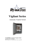
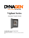
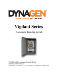
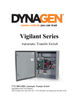
Vigilant Series Automatic Transfer Switch VTS 1000/1250A Automatic Transfer Switch Installation and User Manual Full Version File: VTS 1000/1250A Rev1.6.doc, September 2013 Thank You For Purchasing This DynaGen Product Please Read Manual Before Installing Unit Receipt of Shipment and Warranty Return Information Upon receipt of shipment, carefully remove the unit from the shipping container and thoroughly examine the unit for shipping damage. In case of damage, immediately contact the carrier and request that an inspection report be filed prior to contacting DynaGen. All returned items are to be shipped prepaid and include a Return Material Authorization (RMA) number issued by DynaGen. RMA forms are available by contacting DynaGen Technical Support through the contact methods listed below. Limited Warranty DynaGen will repair or replace any Vigilant Transfer Switch which proves to be defective under normal and proper use within Three Years from the date of shipment. This constitutes the only warranty and no other warranty shall be implied. We welcome your comments and suggestions. Please contact us at: DynaGen Technologies Inc. Phone: 1-888-396-2436 (902) 562 0133 Fax: (902) 567 0633 Email: [email protected] WEB SITE: www.dynagen.ca Table of Contents VTS 1000A / 1250A Specifications 4 1.0 Vigilant Product Series 5 1.1 Receiving, Handling, and Storage 1.1.1 Receiving: 1.1.2 Handling 1.1.3 Storage 6 1.2 Vigilant Product Number Identification 7 2.0 Vigilant Series Installation and Wiring 2.1 General Information 2.2 Mounting Location 2.3 Recommended Upstream Protection 2.4 Power Connections 2.5 VTS 1000/2000 Series Customer Connections 8 3.0 Vigilant Series General Operation 12 4.0 Vigilant Series adjustments and settings 4.1 System adjustment 4.2 Timer adjustment 4.3 Test adjustment 13 5:0 Open Type Transfer Switches 17 6.0 Manual Transfer of Mechanism 18 7.0 Recommended Maintenance 20 8.0 Drawings 8.1 VTS 1000A General Arrangements 8.2 VTS 1250A General Arrangements 8.3 VTS 1000 Series Wiring Diagrams 8.6 VTS 2000 Series Wiring Diagrams 21 9.0 Exerciser 29 10.0 Service Notes 32 VTS 1000/1250A Specifications Vigilant Series Transfer Switches do not support Delta configurations. Vigilant Series UL1008 AC Current Rating AC Voltage Rating Ambient Temperature Rating RSC Rating DC Operating Voltage DC Power Cons. Control Setting Ranges* 1000 series 2000 series Controls not included Controls included Emergency Standby rated. 1000/1250A, 2-pole, 3-pole, 4-pole 120/240V, 120/208V, 277/480V AC Voltage sensing is line to neutral.1 0 113 F (45℃) at 1000A 1130F (45℃) at 1250A 1310F (55℃) at 900A 1310F (55℃) at 1080A 0 149 F (65℃) at 750A 1490F (65℃) at 900A 1580F (70℃) at 700A 1580F (70℃) at 840A 0 0 Do not exceed 158 F (70 C). Do not exceed 1580F (700C). 10A Maximum 12/24 VDC (Voltage Range 9 - 30 VDC) 25mA @ 12 VDC Function Time Delay Engine Start Range 3-32 seconds Time Delay Transfer to Emer. Time Delay Transfer to Norm. Time Delay Engine Cooldown Neutral delay (TDNP) ** Norm. Line Sensing Under Voltage 11-64 seconds Norm. Line Sensing Under Frequency Emer. Line Sensing Under Voltage Emer. Line Sensing Under Frequency Over/Under Voltage Sensing* Over/Under Frequency Sensing* Exerciser Timer Test switch 9-256 seconds 0-256 seconds 0-64 seconds Dropout (11-18%) Pickup (6-13%) (+/- 2% accuracy) 5-12% (+/- 1% accuracy) Dropout (11-18%) Pickup (6-13%) (+/- 2% accuracy) 5-12% (+/- 1% accuracy) Setting 13 seconds (1.56Vdc@ TP J2-1) 21 seconds (0.78Vdc@ TP J2-2) 256 seconds (5.00Vdc@ TP J2-3) 256 seconds (5.00Vdc@ TP J2-4) 10 seconds (0.78Vdc@ TP J2-5) Dropout (18%) Pickup (13%) (+/- 2% accuracy) 12% (+/- 1% accuracy) Dropout (18%) Pickup (13%) (+/- 2% accuracy) 12% (+/- 1% accuracy) Dropout (11-18%) Pickup (6-13%) adjustable Percentage above or below normal voltage to recognize an unacceptable voltage condition. (+/- 2% accuracy) 5-12% adjustable Percentage above or below normal freq to recognize an unacceptable frequency condition. (+/- 1% accuracy) Included on 2000 series transfer switch Included on 2000 series transfer switch UL Withstand / Closing Ratings 20,000A with properly rated 1250A circuit breaker@480V (1000A) 25,000A with properly rated 1600A circuit breaker@480V (1250A) Lug Capacities 1000/1250A – 2 to 600MCM Overall Dimensions 1000-1250A/Open Type – 34” x 46” x 0.5” 1000-1250A/Enclosure - 36” x 60” x 24” Weight 1000A @ 510 LB, 1250A @ 542 LB *Applies to 2000 series only. **Optional Feature. 1 One of the connected L-N phases must be below the under-voltage threshold to initiate transfer sequence. 1:0 Vigilant Product Series: The VTS series transfer switch consists of 2 uniquely designed product series. Product series consist of the 1000 or 2000 series. Each series has been specifically designed with its own unique operating functionality. The 1000 series is represented by the VTS1 product identifier. The 1000 series provides a basic transfer switch mechanism with no control circuitry provided. The 1000 series is specifically designed with a 12 position terminal block provided to allow customer addition of suitable control circuitry as desired. The 2000 series is represented by the VTS2 product identifier. The 2000 series is specifically designed with all required sensing circuitry provided. The sensing circuitry allows automatic transfer of an electrical load to a stand-by power source in the event of an over/under voltage or frequency condition on any or all phases of the normal power source. Upon the restoration of the normal supply, the electrical load will be automatically re-transferred to the normal power source. Optional engine controls may be added to allow the safe operation of the generator including proper engine failure shutdown. All Vigilant Transfer switch mechanisms incorporate a double throw action switching devise for automatic transferring. The VTS mechanism is a contactor operated device controlled by a set of normal and emergency solenoids. Manual operation is also provided for manual transfer of the load between the power sources if necessary. VTS 1000 Series VTS 2000 Series 1:1 Receiving, Handling, and Storage Receiving: Every effort is made to ensure that your vigilant transfer switch arrives at its destination undamaged and ready for installation. The packing is designed to protect the transfer switches internal components as well as the enclosure. Care should be taken to protect the equipment from impact at all times. Do not remove the protective packaging until the equipment is at the installation site and ready to be installed. When the transfer switch reaches its destination, the customer should inspect the shipping box and transfer switch for any signs of damage that occurred during transportation. Any damage should be reported to a DynaGen representative once a thorough inspection is complete. A shipping label affixed to the shipping box includes a variety of product and shipping information, such as items and Customer numbers. Make certain that this information matches your order information. Each transfer switch enclosure is packaged in its own box. Heavy-duty cardboard sides surround the enclosure for protection. Do not discard the packing material until the transfer switch is ready for installation. Important documents will be found inside the Vigilant transfer switch enclosure protective packaging box including the Vigilant transfer switch user manual, VTSC100 controller manual (2000 series) and system wiring diagrams are included. Handling: As previously mentioned, each Vigilant transfer switch is packaged in its own individual box. Protect the equipment from impact at all times and do not double stack. Once the transfer switch is at the installation site and ready to be installed, the packaging material may be removed. Storage: Although well packaged, this equipment is not suitable for outdoor storage. If the transfer switch is to be stored indoors for any period of time, it should be stored with its protective packaging in place. Protect the transfer switch at all times from excessive moisture, dirty conditions, corrosive conditions, and other contaminants. It is strongly recommended that the package-protected equipment be stored in a climate-controlled environment of -20 to 65°C (-4 to 149°F), with a relative humidity of 80% or less. Do not stack other equipment on top of the stored switches. 1.2 Vigilant Catalog Number Identification The Vigilant Transfer Switch product numbering scheme provides significant information pertaining to a specific model. The product Number Identification Table (see Table 1) provides the required interpretation information. An example is offered to initially simplify the process. A product number VTSX-XXXX-X-XXX-XX-X-XX-XX would consist of a combination of information from the following table. TABLE1: IDENTIFICATION TABLE Position 1-4 Position 6-9 Position 11 Position 13-15 Position 17-18 Position 20 Position 22-23 Position 25-26 Series Amperage Phase AC Voltage DC Voltage TDNP Enclosure Labeling VTS1=1000 VTS2=2000 0100=100A 0200=200A 0400=400A 0600=600A 1000=1000A 1250=1250A 2=single 3=three 4=four 240=240V 208=208V 480=480V 12=12V 24=24V X=none D=Delay N1=nema1 N3=nema3 N4=nema4 NX=Open LS=DynaGen LX=Custom Example: The product number VTS2-1250-3-480-12-D-N4-LS would be described as follows: The transfer switch has the VVTSC100 controls included. The transfer switch is designed for a 3 phase 480V system with a current rating of up to 1250A maximum. The transfer switch may be installed in a 12VDC system. The transfer switch comes with Delay on Neutral option (TDNP) and shipped in a Nema 4 enclosure. The transfer switch includes DynaGen labeling. VTS2-1250-3-480-12-D-N4-LS 2:0 Vigilant Series Installation and Wiring: 2:1 General Information: All Vigilant transfer switches are factory tested and approved. Customer installation requires the mounting of the transfer switch as well as all external wiring for normal and emergency operation. Once the transfer switch is properly installed, it should be visually inspected and approved before any testing is performed. 2:2 Mounting Location: Vigilant Series Transfer Switches do not support Delta configurations. WARNING: Adequate lifting means must be used to lift and mount the transfer switch during installation. Failure to do so could result in personal injury. All Vigilant transfer switches require that adequate lifting means are used to install the switch at its mounting location. Be certain to choose a location that offers a flat mounting surface which is capable of supporting the transfer switch (see product specifications for proper weight details). Caution must be taking at the installation site to make sure the site is free from excessive moisture, fluctuating temperature ranges, dust, corrosive materials etc. Before any drilling takes place be certain the drilling area is free of any hazards including electrical wiring, piping etc. Extreme caution should be exercised when any installation and drilling are performed to protect the transfer switch from any debris including contaminants, filings etc. Any debris within the transfer switch may result in a system malfunction. 2:3 Recommended Upstream Protection When protected by a circuit breaker rated at 1250A maximum for 1000A rated transfer switches. This switch is suitable for use on a circuit capable of delivering not more than: 20,000A RMS SYMMETRICAL AT 480V When protected by a circuit breaker rated at 1600A maximum for 1250A rated transfer switches. This switch is suitable for use on a circuit capable of delivering not more than: 25,000A RMS SYMMETRICAL AT 480V Use copper or aluminum wiring 60/75C rating for power terminals. WARNING: Power lines may carry high voltage which can cause serious injury or death. Extreme caution must be exercised when any power connections are being installed to the transfer switch. All power connections must be de-energized before any installations are performed. 2:4 Power Connections: Proper power cables need to be installed to the transfer switch and should be installed by qualified professionals only. Improper installation or connections of these power cables are extremely dangerous and may cause severe injury or death. All power connections are to be connected to the proper lugs which are included on the switch contactor and neutral block assembly. Connect the Normal, Emergency, Neutral and load cables to the terminals which are clearly marked on the transfer switch (see figure 1). Verify that all connections are correct before tightening lugs. All power cable lug connections must be tightened to the proper torque values as shown in table 2. FIGURE 1: Power Cable Connection Locations Utility Ca b le Lug s Em e rg enc y Cab le Lug s Lo a d C a b le Lug s Ne utra l Lug s WARNING: 1000/1250A models include factory installed protective shields covering the power connections of the switch mechanism. Be certain to reinstall the supplied transparent protective shields to the switch mechanism after the proper connections are performed. TABLE 2: 400-600A Lug Torque Values Internal socket size across flats in inches 3/8 Tightening torque in inch pounds 375 Wire size range 2 to 600MCM copper using illsco lug # PB4-600 for 1000/1250A systems 2.5 VTS 2000 Series Customer Connections N.O. dry contacts Generator Battery + Battery - Transfer Switch (Internal) SPST Remote Start (Optional) Contacts – To Generator - + 12/24VDC Generator Battery Please note the VTS2000 Series Transfer Switch consists of the above 6 position terminal block for customer connections. o Battery + and Battery - must be connected for operation of the VTSC100 controller. Either 12VDC or 24VDC. A 1A fuse should be placed on the Battery + connection. Do not use an isolated power supply to power the controller as the controller requires a reference to neutral for AC Sensing which it obtains from the distribution system via battery -. o RSC1 and RSC2 need to be connected to the remote start/stop connections of the generator to allow automatic starting. These are N.O. dry contacts. o An optional customer supplied test switch may be installed by the customer using the Test 1 and Test 2 terminals. A closed circuit between the test connections will simulate a utility failure. See wiring diagram for details. The battery charger needs to be of high quality. Low quality battery chargers will often go into full recharge mode due to VTSC100 (VTS2 controller) current draw. This will quickly wear out the battery. VTS 1000 Series Customer Connections * Please note the VTS1000 Series Transfer Switch consists of the above 12 position terminal block for customer sensing connections. See wiring diagram for sensing positions. VGA – Emergency Voltage Sensing Phase A VGA – Emergency Voltage Sensing Phase B VGA – Emergency Voltage Sensing Phase C VNA – Normal Voltage Sensing Phase A VNA – Normal Voltage Sensing Phase B VNA – Normal Voltage Sensing Phase C A1/BT1 – VNA Contactor Sensing B1/AT1 – VGA Contactor Sensing Neutral – Power Neutral Line Ground – Ground Connection Location SS2 – Remote Start contacts* SS1 – Remote Start contacts* *Applying 12VDC between SS2 and SS1 will energize a relay causing a manual transfer to emergency of the transfer switch. 3.0 Vigilant Series General Operation: The VTS series transfer switch in combination with DynaGen’s VTSC100 timing module will allow for the automatic transfer of an electrical load to a stand-by power source in the event of an over/under voltage or frequency condition on any or all phases of the normal power supply. In the event of an over/under voltage or frequency condition of utility power, the onboard VTSC100 sensing circuitry will begin the initiation of the transfer process. Upon initial sensing of a loss of utility power the Vigilant series transfer switch is specifically designed to allow an engine start time delay period (TDES) to expire before starting the generator. This engine start time delay is user adjustable from the VTSC100 preventing unnecessary engine starts from a temporary loss of utility. In the event the utility source is not restored after the engine start time delay has expired the remote contacts will close sending a signal to the generator’s automatic start controller. When the VTSC100 senses that the generator has started, and is within acceptable limits, the transfer switch will wait until the normal to emergency time delay (TDNE) has expired before switching to the neutral position. While in the neutral position the transfer switch will transfer back to normal supply if the utility is restored. With no utility source the transfer switch will stay in the neutral position until the delay on neutral time has expired allowing the transfer switch to temporarily stop at the neutral position during either the normal to emergency or emergency to normal transfers. The temporary stop allows controlled isolation between both normal and emergency sources. After the neutral delay has expired the transfer switch will complete the transfer to the destination source. All connected loads will be transferred to the emergency power source. While the transfer switch is in the emergency position, the VTSC100 will constantly monitor the utility source voltage and frequency status. Once the utility source is restored the transfer switch will wait until the emergency to normal time delay (TDEN) has expired before switching to the neutral position. The TDEN delay is user adjustable from the VTSC100 to prevent unnecessary transfers caused by momentary utility restoration conditions. If the utility source remains stable after the emergency to normal time delay expires the transfer switch will transfer to the neutral position. The transfer switch will stay in the neutral position until the delay on neutral time has expired. If the utility source fails during this delay period, there will be a transfer back to the emergency position. When the delay on neutral time expires the transfer switch will transfer to the normal position. All connected loads are transferred to the normal power source. When connected loads are transferred back to the normal power source an engine cooldown period (TDEC) will be initiated allowing the generator to run in a no load condition. This engine cooldown time delay is user adjustable from the VTSC100 allowing the generator to continue running for an adjustable period after the normal utility is restored. 4:0 Vigilant Series adjustments and settings: Danger: Never adjust settings while energized. Completely isolate all sources of power from controller and transfer switch mechanism before making any adjustments. The Vigilant Series adjustments and settings may be made from the onboard VTSC100 transfer switch controller (* VTS 2000 series only). The general settings and adjustments for the VTS 2000 series are as follows. Please refer to the VTSC100 controller user manual for detailed information on adjustments. .1 System Adjustments: 1: 120/240 or 277/480 VAC: Switch #1. The dip switch located on the VTSC100 is used to set the unit for 120/240 or 277/480 VAC systems. When switch location #1 is off, the system is configured for a 120/240 VAC system. When switch location #1 is on, the unit is configured for a 277/480 VAC system. 2: 50/60 HZ: Switch #2. The dip switch located on the VTSC100 is used to set the unit for 50 or 60 Hz systems. When switch location #2 is on, the system is configured for 60 Hz. When switch location #2 is off, the unit is configured for 50 Hz systems. 3: Load/No Load: Switch #3. The dip switch located on the VTSC100 may be used for load/no load exerciser testing. When switch location #3 is on, the system is configured for a load test condition allowing transfer to an emergency power source. When switch location #3 is off, the unit is configured for a no load test condition with no transfer to an emergency power source. This setting applies to the engine exerciser test only. Please refer to the VTSC100 user manual for a more advanced and detailed outlook. 4: Under/Over voltage: Switch #4, 5, 6. The dip switch located on the VTSC100 may be used to set the Over/Under voltage setting. Depending upon the positions of Dip Switch locations 4, 5 and 6 the VTSC100 will determine the percentage range to recognise a utility failure. The failure percentage adjustments can range from 11 to 18 percent of the normal power source for dropout and 6 to13 percent for pickup. Switch 4, 5, and 6 off for 18% and on for 11% dropout. Please refer to the VTSC100 user manual for a more advanced and detailed outlook. 5: Under/Over Frequency: Switch #7, 8, 9 The dip switch located on the VTSC100 is used to set the Over/Under frequency setting. Depending upon the positions of Dip Switch locations 7, 8 and 9 the VTSC100 will determine the percentage range to recognise a utility failure. The failure percentage adjustments can range from 5 to 12 percent of the normal power source. Switch 7, 8, and 9 off for 12% and on for 5% range. Please refer to the VTSC100 user manual for a more advanced and detailed outlook. 4.2 Timing Adjustments: (*VTS 2000 series only*) 1: TDES: Time Delay Engine Start: This delay prevents unnecessary engine starts. When the VVTSC100 determines a utility failure it will wait for the engine start time delay to expire before trying to start the generator. 2: TDNE: Time Delay Normal to Emergency: This delay allows the generator to stabilize before any load is transferred. This normal to emergency time delay allows the generator to be fully running before supplying power to a load. 3: TDEN: Time Delay Emergency to Normal: This delay allows the utility source to be monitored for stability. This emergency to normal time delay allows the utility to be monitored for the set amount of time to confirm that it is fully restored and stable. 4: TDEC: Time Delay Engine Cool: This delay allows the engine to continue running after the transfer switch returns to the normal position. When the VTSC100 recognizes that the transfer switch is in the normal position after a emergency to normal transfer, the generator will continue to run under a no load condition until the engine cool time delay has expired. 5: TDNP: Time Delay Neutral Position: This delay allows the transfer switch to temporarily stop between normal to emergency and emergency to normal transfers. The temporary stop allows controlled isolation between the both normal and emergency sources. 4.3 Testing Adjustments: (*VTS 2000 series only*) 1: Controller test switch: Manual testing of DynaGen’s VLC 2000 series transfer switches may be achieved by manual adjustment of the test switch located on the VTSC100. The controller test switch will allow manual testing of the transfer switch. The purpose of the test switch is to simulate a utility power failure. Normally the test switch would be set to the normal position, allowing proper sensing for normal utility faults. To simulate a utility fault when no fault actually exists, the test switch would be set to the test position allowing the transfer switch to transfer to the emergency position. After testing, utility power can be restored simply by setting the test switch back to the normal position. 2: Remote test switch: The remote test switch will allow remote testing of the transfer switch. The purpose of the test switch is to simulate a utility power failure. The remote test switch may be installed by the customer; the switch would be installed between the test 1 and test 2 on the terminal block. Normally the test switch would be set to the Disable position. To simulate a utility fault, the test switch would be set to the Enable position allowing the transfer switch to transfer to the emergency position. A SPST test switch rated at a minimum of 1A should be used. 3: Exerciser The purpose of the exerciser is to perform a test of the transfer switch either manually or automatically. The exerciser may be customer adjusted to any specific time or day in which to perform a test. The exerciser can perform a test for a load or no load condition. For details instructions on operational and setting instructions see the “Exerciser” section on page 29. 5.0 Open Type Transfer Switches: Open type options allow transfer switches to be shipped with no enclosures. All open type UL approved transfer switch will be required to be placed in a minimum size enclosure to allow proper spacing between electrical components and the enclosure wall. The following chart shows the minimum required dimensions to allow the safe operation of these Switches. Transfer Switch Amperage Rating Enclosure Dimensions (Height x Width x Diameter) 1000A 1250A 36 x 60 x 24 36 x 60 x 24 The transfer switch must be in accordance with the following requirements: For models VTS 1000 or 2000 series rated at 400A or above: For models @ 240V 1. The minimum spacing requirements per UL-1008 must not be less than 1/4” through air and 3/8" over the surface of the insulating material. These measures must exist between any uninsulated live part and another uninsulated live part of opposite polarity, uninsulated grounded part other tan the enclosure or any exposed metal part. 2. Not less than 1/2" measured over the shortest distance between any uninsulated live parts and the walls of the metal enclosure, including fittings for conduit or armored cable. For models @ 480V 1. The minimum spacing requirements per UL-1008 must not be less than 3/8” through air and 1/2" over the surface of the insulating material. These measures must exist between any uninsulated live part and another uninsulated live part of opposite polarity, uninsulated grounded part other tan the enclosure or any exposed metal part. 2. Not less than 1/2" measured over the shortest distance between any uninsulated live parts and the walls of the metal enclosure, including fittings for conduit or armored cable. 6.0: MANUAL TRANSFER OF MECHANISM WARNING: Manual transferring is not recommended. If performing an emergency manual transfer, be certain to isolate the transfer switch from all power and load sources. Never transfer under load. Manual transferring is not recommended. If the transfer switch fails to transfer in an emergency, an optional manually transfer may be performed. Caution must be taken to confirm that the transfer switch is isolated from all possible load sources before transferring. Significant force must be supplied to the removable lever handle to perform the transfer. When performing a mechanical transfer the contactor must be properly activated as follows: The manual transfer lever (M) located on the contactor is used to manually transfer between the normal (utility) and emergency (generator) position. A separate removable lever handle is used to transfer the mechanism. See transfer instructions on the switch mechanism. Never transfer under a load condition. Always remove the handle from the manual transfer lever location after each transfer. Up M Removable Lever Handle Trip Se le c t Manual Transfer Lever Location To transfer from Normal to Emergency position: 1. Push “Trip” using an object such as a screwdriver to open the normal poles. 2. Set removable handle on “M” and operate in the “up” direction while pushing “select” with the screwdriver. To transfer from Emergency to Normal position: 1. Push “Trip” using an object such as a screwdriver to open the emergency poles. 2. Set removable handle on “M” and operate in the “up” direction. The transfer switch is in the normal position when reference A on the contactor is set to the ON position and reference B is set to the OFF position. The transfer switch is in the emergency position when reference A on the contactor is set to the OFF position and reference B is set to the ON position as seen in the 400A manual transfer detail. The switch should only need to be transferred manually in the event of a failure within the VTS controls. Please call technical support if any transfer failures are observed. 7.0 RECOMMENDED MAINTENANCE WARNING: When performing any maintenance of the mechanism, isolate the transfer switch from all possible sources of power. Periodically inspect all terminals (load, line and control), and all fasteners for any loose parts or wiring. Periodically inspect all terminals (load, line and control), and all fasteners for tightness. Test the transfer switch operation upon initial installation. Periodically check for any excessive wear on any mechanical operating parts or wiring connections. Clean or replace parts when necessary. All transfer switch parts are made of corrosion resistant material or is plated, coated or painted for corrosion protection. Procedure Action Making the transfer switch safe for inspection and maintenance. Inspect transfer switch location for possible safety hazards Disconnect all possible power sources before switch inspection. Inspect mounting location for any safety or fire hazards. Inspect for dirt, wiring damage and mechanical damages. Check all hardware including controller, exerciser, terminals etc. for any looseness due to vibrations etc. Check for any discoloration, melting or blistering of any wiring or connections Perform regular testing of the switch to check for proper operation in case of emergency Inspect transfer switch for loose hardware. Check for any overheating due to loose connections Perform regular testing of transfer switch 8:1 VTS 1000A - 3 GENERAL ARRANGEMENT 8:2 VTS 1250A - 3 GENERAL ARRANGEMENT 8:3 VTS1-1000/1250-2-240-12 WIRING DIAGRAM 8:4 VTS1-1000/1250-3-208-12 WIRING DIAGRAM 8:5 VTS1-1000/1250-3-480-12 WIRING DIAGRAM 8:6 VTS2-1000/1250-2-240-12/24 WIRING DIAGRAM 8:7 VTS2-1000/1250-3-208-12/24 WIRING DIAGRAM 8:8 VTS2-1000/1250-3-480-12/24 WIRING DIAGRAM 10 ENGINE EXERCISER AND EXTERNAL LED ANNUNCIATION Introduction NEMA 1 All Vigilant 2000 series transfer switches include an external engine exerciser and LED annunciation. The engine exerciser is easily adjustable from outside the transfer switch enclosure. External LED indication is included on all Vigilant 2000 series switches allowing visual controller status. The user may set the engine exerciser to simulate a utility power failure and test the functionality of the transfer switch system. The exact day and time may be specified for testing. External LED indication is available for normal available, emergency available, transfer to normal, transfer to emergency and exercise/test run illumination is explained in detail in the VTSC100 user manual. The functions of the exerciser time clock are described below. The exercise time clock is used to set specific times to test the transfer switch operation. The RESET BUTTON initializes the time clock erasing any previous program. The following will explain how to: 1. 2. 3. 4. Set current time and date Set program timing Review your program On/Auto/Off mode NEMA 3 Note: The exerciser clock has a backup battery. The clock runs off the battery when utility power is not available. The battery is not rechargeable. Set current time and date: 1. Press Clock and Day buttons until current day shows. Release both buttons for current day setting. 2. Press Clock and Hour buttons until current hour shows. Release both buttons for current hour setting. 3. Press Clock and Min buttons until current minute shows. Release both buttons for current minute setting. 4. After setting the weekday and time, the seconds will be set automatically. Set program timing: 1. Press timer button on the exerciser clock. The “1ON” will appear at the left side of the display. The “1ON” represents when the system test will begin. 2. Press Day button to select the program day period. There are 10 possible choices to choose from which can be selected be repeatedly pressing the Day button. The 10 possible selections are: 1. 2. 3. 4. 5. Mo. to Su. Mo. Tu. We. Th. 6. 7. 8. 9. 10. Fr. Sa. Su. Mo. to Fr. Sa. to Su. 3. Press Hour button to set hour. 4. Press Min button to set minute. 5. After setting the above testing start time, press the Timer button. After pressing the Timer button the “1OFF” will appear at the left side of the display. The “1OFF” represents when the test will end. 6. Repeat the above steps 2, 3 and 4 to set the time when the system test is to end. 7. The exerciser timer gives the user 6 different start and end set times if required. Program review: 1. Repeatedly press Timer button to advance display to each subsequent “On” or “Off” user settings. 2. The user set Days and Times will be displayed. 3. To make a change in a specific setting, Repeat Set Program timing above. On/Auto/Off mode: 1. The On/Auto/Off mode may be selected by pressing the manual button. 2. When the On mode is selected, the transfer switch will go directly to the test mode. The test mode will stay active until the On mode is unselected. 3. When the Auto mode is selected, the timer will monitor the user settable program times. The transfer switch will be tested using the programmed start and end times. 4. When the Off mode is selected, the timer will not monitor any user settable program times. The exerciser will not signal to start the generator when it is in the “off” mode. Please note: When the transfer switch is not connected to an energized utility source, the exerciser timer will use an internal battery for memory storage. With the exerciser in the OFF position very little current draw is required. With the exerciser in the ON position a larger current draw is required. With the exerciser in the AUTO position very little current draw is required when the program in not initiated. See chart below for internal battery current draw: Exerciser Position Current Draw ON OFF AUTO (program not initiated) AUTO (program initiated) 80 uA/Hour 5 uA/Hour 5 uA/Hour 80 uA/Hour The internal battery current draw would not be applicable when an energized utility source is supplying power to the switch. SERVICE NOTES-1000A, 1250A. VIGILANT ATS 1000 and 2000 series CONTENTS PAGE Replacement Parts Identification. Wiring Diagram and Wiring Harness Identification. Control Board Replacement. Switch unit Replacement. Switch Lug Replacement. Timer Replacement. LED Board Replacement. Wiring Harness Replacement. Neutral Plate Replacement. Neutral Plate Lugs Replacement. 33 33 33 35 36 37 37 38 38 38 REPLACEMENT PARTS Figure 1. The listing below identifies replacement parts. Order by using the description and stock code number. In addition, provide the serial number of the transfer switch in question. Description Stock Code Number 1000A Contactor 2 Pole 1000A Contactor 3 Pole 1000A Contactor 4 Pole 1250A Contactor 2 Pole 1250A Contactor 3 Pole 1250A Contactor 4 Pole Control Board 12v relay. 240v working. neutral delay. Control Board 12v relay. 480v working. neutral delay. Control Board 24v relay. 240v working. neutral delay. Control Board 24v relay. 480v working. neutral delay. 1000A, 1250A Contactor and Neutral lugs 1000A, 1250A Neutral Plate Neutral Insulator Timer (2000 series only) LED Board (2000 series only) Transformer (2000 series only) 12v dc Relay (1000) series only) SWT0052 SWT0053 SWT0054 SWT0055 SWT0056 SWT0057 VTSC100-240-12-D VTSC100-480-12-D VTSC100-240-24-D VTSC100-480-24-D CON 0127 DWG1189R2 INN0005 ACC0073 VTS-ANNH TSF0010 RLY0032 It is recommended that after completing any of the following procedures, a test be performed to verify the proper operation of the transfer switch. WIRING DIAGRAMS and WIRE HARNESS Vigilant Switch Model Wiring Diagram Wire Harness VTS2-1000,1250-2-240-D VTS1-1000,1250-2-240-D VTS2-1000,1250-3-240-D VTS1-1000,1250-3-240-D VTS2-1000,1250-2-480-D VTS1-1000,1250-2-480-D VTS2-1000,1250-3-480-D VTS1-1000,1250-3-480-D 1261R3 1263R1 1208R5 1257R1 1367R1 1268R4 1276R1 1268R4 1276R1 1271R5 1235R6 1265R1 1271R5 1278R1 Figure 1. REPLACEMENT PARTS TO REPLACE THE CONTROL BOARD Use a #2 Phillips screwdriver to undo four screws securing the control board cover and remove. Unplug all the connections to the control board. The green 5-pin connector pulls straight out. The white 9 and 12-pin connectors pull straight out by gripping the connectors such that the top and bottom locking clips on each connector are released by this action. Disconnect the 6-pin connector at the bottom of the control board. Remove seven screws securing the control board to the inner panel. Figure 2. Figure 2. CONTROL BOARD MOUNTING SCREW LOCATIONS The control board can now be removed from the inner panel. Remove each screw, spacer and nylon washer from the old board, and replace in the new board. Do not forget the single self retaining nylon spacer. Figure 3. Figure 3. CONTROL BOARD NYLON SPACERS The replacement control board can now be installed by following this procedure in the reverse order. Note the orientation of the control board when installing. The white 9-pin socket is at the top. Align the control board with the mounting holes. Tighten the screws evenly to avoid undue stress on the circuit board. Tighten to 5in-lb max. Replace the control board cover. TO REPLACE THE SWITCH UNIT First, make certain that the switch is disconnected from all power and control sources. Undo the front cover screws, or open the door depending on the enclosure style. Undo the screws securing the transparent switch covers and remove the covers. Figure 4. Figure 4. TRANSPARENT COVER SECURING SCREWS Figure 5. SWITCH REMOVAL Disconnect all the power and control wiring connections to the switch. Carefully withdraw the power cables from the switch terminals. Make suitable provision for supporting the switch prior to removing any fasteners. For example a shop crane could be employed to take the weight of the switch. Only when you are satisfied that the switch is securely supported, should the switch securing screws be removed, figure 1, and the complete switch unit can then be withdrawn from the enclosure supported from the lifting device. Figure 5. Follow this procedure in the reverse order to install a replacement switch unit. Confirm all wiring connections by consulting the wiring diagram. The individual wires are identified at each end. Do not forget to replace the transparent switch covers. TO REPLACE THE SWITCH LUGS First, make certain that that the switch is disconnected from all power and control sources. If the switch has previously been removed from the inner panel the lugs can simply be removed by unscrewing the fasteners. If the switch is still fastened to the inner panel, proceed by first disconnecting all the sensing wires to the normal and generator lugs. Next, carefully remove all the power cable connections to each lug. Remove the generator lugs first to access the load lug nuts. In some cases it will be impossible to completely remove the load screws due to interference with the inner panel, although complete removal of the screws is not required. Ensure that the lug and switch strap surfaces are clean and flat and that no gaps are present between the surfaces. When replacing the normal and load lugs, note that a flat washer is used on the screw head side in addition to one against the lug, and a spring lockwasher is used under the head of the hexagon nut. The generator lugs employ a spring lockwasher under the head of the screw and flat washer against the lug. Tighten all the screws to 240 in-lb. Reconnect the wire harness sensing wires to the appropriate lugs with reference to the wiring diagram. The wires are identified with a letter on each end corresponding to the wiring diagram connections. TO REPLACE THE TIMER UNIT First, make certain that the switch is disconnected from all power and control sources. Undo the front cover screws, or open the door depending on the enclosure style. Disconnect the timer wiring. Remove four screws securing the timer to the support bracket and lift the timer off. Figure 6. Figure 6. TIMER AND LED BOARD MOUNTING Re-use the four screws and spacers. Follow this procedure in the reverse order to install a replacement timer unit. Do not exceed 5in-lb torque when replacing the timer screws. TO REPLACE THE LED BOARD First, make certain that the switch is disconnected from all power and control sources. Undo the front cover screws, or open the door depending on the enclosure style. Unplug the LED board wire connector. Remove two screws securing the LED board to the support bracket and lift the LED board off. Figure 6. Re-use the two screws and spacers. Note that one 5/8” and one 1” long spacer are used on each screw. Follow this procedure in the reverse order to install a replacement LED board. Do not exceed 5in-lb torque when replacing the LED board screws. Note the orientation of the replacement board. The wire connector is on the right hand side. TO REPLACE THE WIRING HARNESS The replacement wiring harness is supplied as a complete unit, pre-formed as far as possible thus permitting a virtual “drop in” installation once the original harness is removed. First, make certain that the switch is disconnected from all power and control sources. Undo the front cover screws, or open the door depending on the enclosure style. Disconnect the white 9 and 12-pin connectors from the control board. Pull them straight out by gripping the connectors such that the top and bottom locking clips on each connector are released by this action. Disconnect the 6-pin connector at the bottom of the control board. Disconnect the green 5-pin connector from the control board. Pull all the spade terminal connectors from both the switch unit and the timer. Remove the 6-pin connector from the LED board. Disconnect all the wires from the 6-position terminal block and neutral block. Figure 1. Use wire cutters to sever the nylon wire ties to release the original harness at the tie rap base locations. Note the general layout of the original harness before lifting it clear. Install the replacement harness with reference to the wiring diagram for the wire terminations. Individual wires are identified by a letter on each end. Check the installation and replace the nylon tie raps to secure the harness. TO REPLACE THE NEUTRAL PLATE ASSEMBLY Again, make certain that the switch is disconnected from all power and control sources. Undo the front cover screws, or open the door depending on the enclosure style. First, disconnect the wires attached to the neutral plate. The neutral plate is secured to the supporting insulators by four 3/8”-16 x 7/8” long hexagon screws, flat washers and spring lockwashers. Figure 7. By removing these screws the neutral plate assembly may be detached from the insulators. Be sure to grip the insulators with a suitable tool to prevent them from rotating when removing the hexagon screws. Tighten the screws to 240 in-lb. when reassembling, again holding the insulators to prevent them from rotating. TO REPLACE THE NEUTRAL PLATE LUGS The screws securing the lugs are 3/8”-16 x 1 ¼” long hexagon screws, complete with flat washers and spring lockwashers. These thread directly into the neutral plate. Note that there is a flat washer against the lug and a spring lockwasher under the head of the screw. Ensure that the lug and neutral plate surfaces are clean and flat and that no gaps are present between the surfaces. Apply an oxide inhibitor to the lug/plate surfaces. Tighten the screws securing the lugs to 240 in-lb. Figure 7. Figure 7. NEUTRAL PLATE ASSEMBLY


