1
E n g l i s h
ELECTRICAL INSTALLATION
EN61010 - /CSA 22.2 No 1010.1 92
(See important Safety Information page 12)
Compliance shall not be impaired when fitted to the final installation.
Designed to offer a minimum of Basic Insulation only.
OUTPUT DEVICES
Two of the following output devices are fitted to the controllers, depending on the model.
1 Solid state relay drive (SSd/SSd1/SSd2)
5Vdc +0/-15%, 15mA non isolating
To switch a remote SSR (or logic)
2 Miniature power relay (rLY/rLY1) 2A/250V AC resistive, Form A/SPST contacts.
3 Sub miniature power relay (rLY2) 1A/250V AC resistive, Form A/SPST contacts.
OUTPUT DEVICE ALLOCATION
Any of the available outputs may be chosen for the main setpoint (SP1), the remaining
device being automatically allocated to the second setpoint (SP2).
Dual relay or dual SSd output models are available to order. Please contact your
local CARLO GAVAZZI distributor for details.
Designed for use with the following supply voltages:
1). 100 - 240V 50-60 Hz 4.5 VA (nominal) +/-10% maximum permitted fluctuation
The body responsible for the installation is to ensure that supplementary insulation suitable
for Installation Category II or III is achieved when fully installed.
To avoid possible hazards, accessible conductive parts of the final installation should be
protectively earthed in accordance with EN6010 for Class 1 Equipment.
Output wiring should be within a Protectively Earthed cabinet.
Sensor sheaths should be bonded to protective earth or not be accessible.
Live parts should not be accessible without the use of a tool.
When fitted to the final installation, an IEC/CSA APPROVED disconnecting device should be
used to disconnect both LINE and NEUTRAL conductors simultaneously.
A clear instruction shall be provided not to position the equipment so that it is difficult to
operate the disconnecting device.
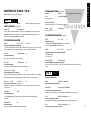
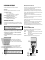
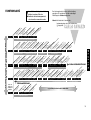
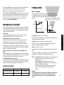
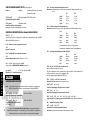
TYPICAL CONNECTION DIAGRAM
In this example the SSR driver output is allocated to SP1 and wired to switch the load
(heater) using an SSR.
F1 Fuse:
1A time lag type to IEC127. CSA/UL rating 250Vac
F2 Fuse:
High Rupture Capacity (HRC) Suitable for maximum rated load current
S1 Switch:
IEC/CSA/UL Approved disconnecting device
2). 12V - 24V (AC/DC) +/-20% 4.5 VA Polarity not required
WIRING THE CONNECTOR
Prepare the cable carefully, remove a maximum of 8mm insulation and ideally tin to avoid
bridging. Prevent excessive cable strain. Maximum recommended wire size: 32/0.2mm
1.0mm2 (18AWG).
Comms option
(when fitted)
9
+
INDUCTIVE LOADS
1
To prolong relay contact life and suppress interference it is recommended engineering
practice to fit a snubber (0.1uf/100 ohms) between terminals 5 and 6.
10 11 12 13
–
2
Sensor
+
–
3
4
5Vdc 15mA
S1
10
6
16
L
N
7
8
Supply
Open in
alarm
state
CAUTION:
+
Line
F2
Neutral
5
Output Output
SP2
SP1
Sensor
Snubber leakage current can cause some electro-mechanical devices to be held
ON. Check with the manufacturers specifications.
14 15
F1
SSR
–
Load