1
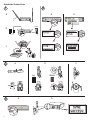
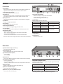
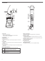
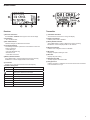
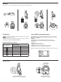
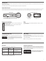
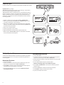
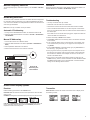
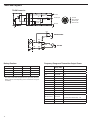
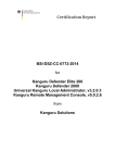
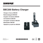
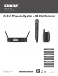
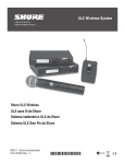
ULX-D
ULX-D Digital Wireless Microphone System
©2011 Shure Incorporated
27A16234 (Rev. 1)
27A16234
ii
IMPORTANT SAFETY INSTRUCTIONS
1.
2.
3.
4.
5.
6.
7.
8.
9.
10.
11.
12.
13.
READtheseinstructions.
KEEPtheseinstructions.
HEEDallwarnings.
FOLLOWallinstructions.
DONOTusethisapparatusnearwater.
CLEANONLYwithdrycloth.
DONOTblockanyventilationopenings.Installinaccordancewiththemanufacturer’s
instructions.
DONOTinstallnearanyheatsourcessuchasradiators,heatregisters,stoves,orother
apparatus(includingamplifiers)thatproduceheat.
DONOTdefeatthesafetypurposeofthepolarizedorgroundingtypeplug.Apolarized
plughastwobladeswithonewiderthantheother.Agroundingtypeplughastwoblades
andathirdgroundingprong.Thewiderbladeorthethirdprongareprovidedforyour
safety.Iftheprovidedplugdoesnotfitintoyouroutlet,consultanelectricianforreplacementoftheobsoleteoutlet.
PROTECTthepowercordfrombeingwalkedonorpinched,particularlyatplugs,conveniencereceptacles,andthepointwheretheyexitfromtheapparatus.
ONLYUSEattachments/accessoriesspecifiedbythemanufacturer.
USEonlywithacart,stand,tripod,bracket,ortablespecifiedbythemanufacturer,orsoldwiththeapparatus.Whenacartisused,usecautionwhen
movingthecart/apparatuscombinationtoavoidinjuryfromtip-over.
UNPLUGthisapparatusduringlightningstormsorwhenunusedforlong
periodsoftime.
14. REFERallservicingtoqualifiedservicepersonnel.Servicingisrequiredwhentheapparatushasbeendamagedinanyway,suchaspowersupplycordorplugisdamaged,
liquidhasbeenspilledorobjectshavefallenintotheapparatus,theapparatushasbeen
exposedtorainormoisture,doesnotoperatenormally,orhasbeendropped.
15. DONOTexposetheapparatustodrippingandsplashing.DONOTputobjectsfilledwith
liquids,suchasvases,ontheapparatus.
16. TheMAINSplugoranappliancecouplershallremainreadilyoperable.
17. TheairbornenoiseoftheApparatusdoesnotexceed70dB(A).
18. ApparatuswithCLASSIconstructionshallbeconnectedtoaMAINSsocketoutletwitha
protectiveearthingconnection.
19. Toreducetheriskoffireorelectricshock,donotexposethisapparatustorainor
moisture.
20. Donotattempttomodifythisproduct.Doingsocouldresultinpersonalinjuryand/or
productfailure.
Thissymbolindicatesthatdangerousvoltageconstitutingariskof
electricshockispresentwithinthisunit.
Thissymbolindicatesthatthereareimportantoperatingandmaintenanceinstructionsintheliteratureaccompanyingthisunit.
WARNING: ThisproductcontainsachemicalknowntotheStateofCaliforniatocause
cancerandbirthdefectsorotherreproductiveharm.
iii
iv
중요 안전 지침
1.
2.
3.
4.
5.
6.
7.
8.
이지침을정독해주십시오.
이지침을잘보관해주십시오.
모든경고를유의하십시오.
모든지침을준수하십시오.
이기기를물가까이에두고사용하지마십시오.
마른수건으로만닦으십시오.
통풍구를막지마십시오.제조업체의지침에따라설치하십시오.
난방기,방열조절기,스토브,기타열을발산하는기기(앰프포함)근처에설
치하지마십시오.
9. 안전을위해유극또는접지타입의플러그를반드시사용하십시오.유극유형
의플러그에는폭이다른핀이있습니다.접지형플러그에는두개의핀과하
나의접지단자가있습니다.넓은핀이나접지단자는사용자의안전을위한
것입니다.제공된플러그가콘센트에맞지않으면전기기사에게문의하여구
형콘센트를교체하십시오.
10.전원코드는밟히지않도록주의하고특히전원플러그사이,접속소켓및기
기에서나오는부분에전원코드가끼이않도록보호하십시오.
11.제조업체가지정한부속품/부품만사용하십시오.
12.제조업체에서지정하거나기기와함께판매되는카트,스탠드,받
침대,브라켓또는테이블에서만사용하십시오.카트를사용하는
경우,이동시카트와기기가넘어져부상을입지않도록주의하
십시오.
13.낙뢰시또는장기간동안사용하지않을때는기기의전원을빼놓으십시오.
14.모든서비스는자격을갖춘서비스전문가에게의뢰하십시오.전원코드나플
러그가손상된경우,기기안으로액체를들어가거나물건을떨어뜨린경우,
기기가비나물에젖은경우,기기가정상적으로작동하지않는경우또는기
기를떨어뜨린경우와같이기기가손상되었을때는서비스를받아야합니다.
15.기기에물을떨어뜨리거나뿌리지마십시오.물병과같이물이담긴물체를기
기위에올려놓지마십시오.
16.MAINS플러그나기기용커플러는작동가능한상태로남아있어야합니다.
17.AC어댑터의공기매개잡음은70dB을초과하지않아야합니다.
18.CLASSI구조의기기는MAINS소켓콘센트에보호접지연결방식으로연결
되어야합니다.
19.화재나감전위험을줄이려면이기기를빗물또는습기에노출시키지마십
시오.
20.이제품을고치려고시도하지마십시오.그렇게하면사람이다치거나제품이
고장을일으킬수있습니다.
이기호는기기에전기쇼크위험을유발하는위험한전압이
흐른다는것을의미합니다.
이기호는이기기와함께제공된문서에중요한작동및유지
보수지침의내용이들어있다는것을의미합니다.
v
vi
vii
General Description
Shure ULX-D Digital Wireless offers uncompromising audio quality and RF performance, with intelligent, encryption-enabled hardware and advanced rechargeability options for professional sound reinforcement.
A breakthrough in wireless audio quality, Shure digital processing enables ULX-D to deliver the purest reproduction of source material ever available in a
wireless system. Extended 20 Hz – 20 KHz frequency range and totally flat response captures every detail with clarity, presence, and incredibly accurate lowend and transient response. At greater than 120 dB, ULX-D delivers wide dynamic range for excellent signal-to-noise performance. For added convenience,
proprietary Shure Gain Ranging optimizes the system’s dynamic range for any input source, eliminating the need for transmitter gain adjustments.
In RF performance, ULX-D sets the bar for wireless channel efficiency and signal stability. Minimized intermodulation allows more transmitters to operate simultaneously over one TV channel than any other system. Rock-solid RF signal with no audio artifacts extends over the entire 100 meter line-of-sight range,
even using standard dipole antennas. For applications where secure transmission is required, ULX-D offers Advanced Encryption Standard (AES) 256-bit
encrypted signal for unbreachable privacy.
Advanced Lithium-ion rechargeability provides extended transmitter battery life over alkaline batteries, battery life metering in hours and minutes accurate to
within 15 minutes, and detailed tracking of battery health status.
Generations ahead of any other available system in its class, ULX-D brings a new level of performance to professional sound reinforcement.
Features
Uncompromising Professional Digital Wireless
• 24-bit/48 KHz digital audio that exceeds all other systems in accurate
reproduction of the source material
• 20 Hz – 20 KHz frequency range with flat response
• Greater than 120 dB dynamic range for excellent signal-to-noise
performance
• Encryption-enabled for any application where secure transmission is
needed:
• Advanced Encryption Standard (AES-256) conforming to the US
Government National Institute of Standards and Technology (NIST)
publication FIPS-197
• Enabled via front panel menu and IR sync
• Added benefit of eliminating stray RF interference by allowing only
encrypted signal through to the receiver
• Wide selection of trusted Shure Microphones
Rugged, Intelligent Hardware
• Optimized scanning automatically finds and deploys the cleanest
frequencies available
• Proprietary Shure Gain Ranging optimizes the system’s dynamic range for
any input source, eliminating the need for transmitter gain adjustments
• Up to 60 dB of adjustable system gain is easily accessible from the
receiver front panel
• Networkable receiver simplifies setup across multiple channels
• AMX/Crestron control-compatible
• Rugged metal housing on both transmitters and receiver
• Interference detection and alerts provide instant confirmation when
interference is present
• Upgraded LCD screens with adjustable contrast and brightness on both
transmitters and receivers
Extremely Efficient and Reliable RF Performance
Advanced Rechargeability - SB900 Shure
Rechargeable Battery
• Minimized intermodulation distortion results in significantly more
channels on air, setting the bar for wireless performance in crowded RF
environments
• Provides ULX-D transmitters with greater than 12 hours of continuous use
• Up to 64 MHz overall tuning range (region dependent)
• 14 active transmitters in one 6 MHz TV channel
• 17 active transmitters in one 8 MHz TV channel
• Over 60 compatible channels on one frequency band
• Rock-solid signal stability with no audio artifacts extends over the entire
100 meter line-of-sight range using standard supplied dipole antennas
• Lithium-Ion chemistry and intelligent Shure battery circuitry results
in rechargeable batteries with no memory effect. The battery can be
recharged at any time; a complete discharge is never necessary
• Transmitters and receivers display remaining battery life in hours and
minutes accurate to within 15 minutes
• The SBC200 Dual Docking Charger recharges batteries while in
transmitters or out
• Up to four SBC200s can be linked together to provide docked charging of
eight transmitters from one power supply
• The SBC800 Eight-Bay Charger brings up to eight SB900 batteries to full
charge within three hours and 50% charge in one hour, with charge status
LEDs for each battery
• AA alkaline backwards compatibility
• Both chargers fit in a standard-size rack drawer for easy transport and
storage
1
Quickstart Instructions
1
2
a
a
b
control
45°
12V
OUT
150 mA
line
mic
15V 0.6A
antenna . B
power
mic / line
inst / aux
control
power
SCAN
SCAN
sync
push
SCAN
push
push
power
www.shure.com
EXIT
power
mic / line
inst / aux
line
mic
antenna . A
power
mic / line
inst / aux
ULXD4
push
!! !
G:01 CH:21
485.775 MHz
Rssi: -118 dBm
EXIT
www.shure.com
ULXD4
www.shure.com
12V
OUT
150 mA
15V 0.6A
antenna . B
12V
OUT
150 mA
antenna . B
line
mic
power
15V 0.6A
power
line
mic
mic / line
mic / line
control
RF audio
gain
inst / aux
inst / aux
12V
OUT
A150
m 05mA
1
antenna . A
12V
OUT
150 mA
SCAN
antenna . A
push
power
ENTER
sync
EXIT
SCAN
push
control
RF audio
A B
gain
power
OL
ULXD4
OL
ENTER
Digital Wireless Receiver
EXIT
sync
3
SCAN
push
a
b
on
c
on
on
ULXD2
ULXD2
ULXD2
on
AA
SB900
ULXD1
ULXD1
4
a
b
control
!! ! ! ! ! !
on
! ! ! ! ! !!
!!! !
ULXD2
!!!
sync
sync
cm
<15
.)
( 8 in
EXIT
RF audio
gain
power
ENTER
EXIT
Digital Wireless
Receiver
SCAN
sync
RF audio
ULXD4
control
ENTER
push
SCAN
push
sync
gain
power
! ! ! ! ! !!!
on
!!!
SCAN
12V
OUT
A150
m 05mA
1
!! !
15V 0.6A
antenna . B
antenna . B
line
mic
15V 0.6A
!! ! ! ! ! ! !
12V
OUT
150 mA
!! !
SCAN COMPLETE
ULXD4
www.shure.com
2
power
EXIT
ULXD4
12V
OUT
150 mA
c
gain
OL
ENTER
Digital Wireless Receiver
EXIT
12V
OUT
150 mA
RF audio
A B
OL
ULXD4
antenna . A
sync
b
gain
OL
ENTER
Digital Wireless Receiver
RF audio
A B
OL
EXIT
ULXD4
ULXD4
www.shure.com
Receiver
Front Panel
① Sync Button
Press the sync button while the receiver and transmitter IR windows are
aligned to transfer settings from the receiver to the transmitter
7
④ Encryption Icon
Illuminates when AES-256 encryption is activated: Utilities > Encryption ⑤ LCD Panel
Displays settings and parameters
gain
power
OL
ENTER
Digital Wireless Receiver
EXIT
SCAN
sync
1
3
2
push
6
5
4
10
11
12
13
⑩ RF Signal Strength LEDs
Indicate the RF signal strength from the transmitter:
• Amber = Normal (-90 to -70 dBm)
• Red = Overload (greater than -25 dBm)
⑪ Audio LEDs
Indicate average and peak audio levels:
LED
Audio Signal Level
Red (6)
-0.1 dBFS
⑦ Menu Navigation Buttons
Use to select and navigate through parameter menus
Yellow (5)
-6 dBFS
Yellow/ Green (4)
-12 dBFS
⑧ Control Wheel
Push to select menu items for editing, turn to edit a parameter value
Green (3)
-20 dBFS
Green (2)
-30 dBFS
Green (1)
-40 dBFS
Note: the receiver will not output audio unless one blue LED is illuminated
RF audio
A B
OL
⑥ Scan Button
Press to find the best channel or group
⑨ RF Diversity LEDs
Indicate antenna status:
• Blue = normal RF signal between the receiver and transmitter
• Red = interference detected
• Off = No RF connection between the receiver and transmitter
9
control
ULXD4
② Infrared (IR) Sync Window
Sends IR signal to the transmitter for sync
③ Network Icon
Illuminates when the receiver is connected with other Shure devices on
the network. IP Address must be valid to enable networked control
8
Description
Overload/ limiter
Normal peaks
Signal Present
⑫ Gain Buttons
Adjust channel gain
⑬ Power Switch
Powers the unit on or off
Back Panel
① RF Antenna Diversity Input Jack (2)
For antenna A and antenna B.
② Power Supply Jack
Connect the supplied 15 V DC external power supply
③ Network Speed LED (Amber)
• Off = 10 Mbps
• On = 100 Mbps
ULXD4
www.shure.com
12V
OUT
150 mA
antenna . B
line
mic
15V 0.6A
power
1
2
3
4
6
5
mic / line
inst / aux
7
8
12V
OUT
150 mA
antenna . A
1
④ Ethernet Port
Connect to an Ethernet network to enable remote control and monitoring
⑤ Network Status LED (Green)
• Off = no network link
• On = network link active
• Flashing = network link active, flash rate corresponds to traffic volume
⑥ Mic/Line Switch
Applies a 30 dB pad in mic position (XLR output only)
⑦ Balanced XLR Audio Output
Connect to a mic or line level input
⑧ Balanced 1/4" (6.35 mm) TRS Audio Output
Connect to a mic or line level input
Receiver Output Level
The following table describes the typical total system gain from the audio
input to the receiver outputs:
Output Jack
System Gain (gain control = 0dB)
1/4" TRS
+18 dB
XLR (line setting)
+24 dB
XLR (mic setting)
-6 dB*
*This setting matches a typical wired SM58 audio signal level.
3
Transmitters
⑪
①②
③
⑨
ULXD1
④
⑤
⑥
⑦
④
⑤
②
⑥
ULXD2
on
⑦
⑧
⑧
⑩
① Power LED
• Green = unit is powered on
• Red = low battery or battery error (see Troubleshooting)
• Amber = power switch is disabled
② On/Off Switch
Powers the unit on or off
③ TA4M Input Jack
Connects to a 4-Pin Mini Connector (TA4F) microphone or instrument
cable
④ LCD Display:
View menu screens and settings. Press any control button to activate the
backlight
⑤ Infrared (IR) Port
Align with the receiver IR port during an IR Sync for automated transmitter
programming
⑥ Menu Navigation Buttons
Use to navigate through parameter menus and change values.
4
exit
Acts as a 'back' button to return to previous menus or parameters without confirming a value change
enter
Enters menu screens and confirms parameter changes
▼▲
Use to scroll through menu screens and to change parameter values
⑦ Battery Compartment
Requires Shure SB900 rechargeable battery or 2 AA batteries.
⑧ AA Battery Adapter
Handheld: rotate and store in the battery compartment to use a Shure
rechargeable battery pack
Bodypack: remove to accommodate a Shure rechargeable battery pack
⑨ Detachable Bodypack Antenna
For RF signal transmission
⑩ Integrated Antenna
For RF signal transmission
⑪ Microphone Cartridge
See Optional Accessories for a list of compatible cartridges
Home Screen
8
6
1
1
7
5
2
3
6
2
4
3
4
5
Receiver
Transmitter
① Receiver Information
Use UTILITIES > HOME INFO to change the home screen display
① Transmitter Information
Scroll ▲▼ at the home screen to change the display
② Gain Setting
-18 to +42 dB, or Mute
② Power Lock Indicator
Indicates power switch is disabled
③ Mic. Offset Indicator
Indicates offset gain is added to the transmitter
③ Battery Runtime Indicator
Shure SB900 battery: runtime is displayed in minutes remaining
AA Batteries: runtime is displayed with a 5-bar indicator
④ Transmitter Settings
The following information cycles when a transmitter is tuned to the
receiver's frequency:
• Transmitter Type
• Input Pad (Bodypack only)
• RF Power Level
• Transmitter Lock Status
⑤ Battery Runtime Indicator
Shure SB900 battery: runtime is displayed in minutes remaining
AA Batteries: runtime is displayed with a 5-bar indicator
⑥ TV Channel
Displays the TV channel that contains the tuned frequency
Transmitter Setting Icons
Display Icon
Transmitter Setting
-12 dB
Bodypack input is attenuated 12 dB
④ Menu Lock Indicator
Indicates menu navigation buttons are disabled
⑤ Mic. Offset
Displays microphone offset gain value
⑥ RF Power
Displays RF power setting
⑦ Bodypack Input Pad
The input signal is attenuated 12 dB
⑧ Encryption Icon
Indicates encryption is enabled on the receiver and has been transferred
to the transmitter from a sync
Offset gain is added to the transmitter
Lo
1 mW RF power level
Nm
10 mW RF power level
Hi
20 mW RF power level
M
Menu is locked
P
Power is locked
-No TX-
No RF connection between a receiver and transmitter
5
push
control
RF audio
A B
gain
power
OL
ULXD4
OL
ENTER
Digital Wireless Receiver
EXIT
sync
SCAN
push
Batteries
The transmitter runs on two AA batteries or the Shure SB900 rechargeable battery.
3
a
b
on
c
on
on
ULXD2
ULXD2
ULXD2
on
on
AA
SB900
ULXD1
ULXD1
4 AA Batteries
a
b Rechargeable Battery
Shure SB900
A 5-segment icon on the receiver and transmitter menu screens
indicates battery charge.
For accurate battery runtime monitoring, set the transmitter to the appropriate battery type: UTILITY > BATTERY > SET TYPE.
!!! !
AA Battery Runtime Chart (h:mm)
Battery Indicator
RF Power Setting
1/10 mW
20 mW
11:00 to 9:35
5:30 to 4:55
9:35 to 7:15
4:55 to 4:00
7:15 to 4:45
4:00 to 2:30
4:45 to 2:25
2:30 to 1:45
2:25 to 00:45
1:45 to 0:25
00:45 to 00:20
00:25 to 00:10
!!!
8 in
cm (
5
1
<
sync
Detailed information
for the SB900 is displayed in the receiver
ULXD4
EXIT
Wireless
Receiver
BATTERY INFO Digital
menu
and
the transmitter menu: UTILITY > BATTERY >
!! ! ! ! ! !
on
! ! ! ! ! !!
ULXD2
When using an SB900 rechargeable battery, the receiver and
transmitter home screens display the number of hours and mincontrol
RF audio
utes remaining.
gain
power
sync
.)
control
ENTER
SCAN
sync
BATT. STATS
RF audio
gain
power
ENTER
EXIT
push
SCAN
push
HEALTH: Overall battery health
CHARGE: Percentage of a full charge
CYCLES: Number of times the batterysync
has been charged
TEMP: Battery temperature in Celsius and Fahrenheit
Note: For additional rechargeable battery information, visit www.shure.com.
AA Battery Adapter
on
Handheld: Rotate and store in battery door when using Shure SBC900
6
Bodypack: Remove when
using the Shure SBC900
Setting Gain
Adjust gain at the receiver so that the average signal levels are solid green and yellow with peaks that flicker the red overload LED. Attenuate the gain if the
signal overloads repeatedly.
Set the XLR output to line-level when possible to optimize sound system noise performance.
System Gain Control
The gain control on the receiver sets the audio signal level for the entire system. This allows adjustments to be made during a live performance. It is not necessary to change the gain on the transmitter (mic offset) to optimize the gain structure. Any required changes to gain should be made from the receiver.
Adjusting Gain
control
Large Gain Adjustments
RF audio
A B
gain
OL
ULXD4
OL
ENTER
Digital Wireless Receiver
RF audio
AB
power
gain
power
RF audio
A B
OL
OL
L
OL
gain
power
ULXD4
Digital Wireless Receiver
control
or
EXIT
sync
SCAN
sync
push
Reading the Audio Meter
RF audio
A B
OL
OL
Audio peaks illuminate the LEDs for 2 seconds while RMS signal
is displayed in realtime.
gain
power
OL (Overload) LED: Illuminates red when the internal limiter is
EXIT
SCAN
push
Use the control wheel in
the AUDIO menu
Press and hold a
gain button
Press the ▲▼ gain buttons on the front of the receiver to incrementally adjust gain from -18 to +42 dB.
OL
ENTER
Mute
To mute the audio, use Shure Wireless Workbench® software or a thirdparty control device.
engaged, preventing digital clipping.
Transmitter Input Clip
The following warning displays on the receiver LCD panel when the transmitter input is clipped:
Tx OVERLOAD
To correct, attenuate the signal source. If the source
cannot be attenuated while using a bodypack transmitter, select INPUT PAD from the main menu to attenuate
the input signal 12 dB.
Mic. Offset
Use this to compensate for signal level differences between transmitters
that share the same receiver.
Set the offset gain on a low signal level transmitter to match a louder transmitter: Utility > Mic.Offset
Note: For normal gain adjustments, use the receiver gain buttons.
RF
RF Power
Reference the following table for setting RF Power:
RF Power Setting
System
Range
Application
1 mW
33 m (100 ft.)
For increased channel reuse
at close distances
10 mW
100 m (330 ft.)
Typical setups
20 mW
100 m (330 ft.)
For hostile RF environments
or long-distance applications
Interference Detection
Interference Detection analyzes the quality of the RF signal and detects interference conditions that have caused an audio signal dropout. When interference is identified, the RF LEDS illuminate red and the following warning
displays on the receiver LCD panel.
Perform a Scan and Sync during a performance break if the warning display persists
or the audio drops out repeatedly.
Note: Using the 20 mW setting decreases the transmitter battery runtime
and reduces the number of compatible systems.
7
Scan and Sync
EXIT
Use this procedure to tune a receiver and transmitter to the best open channel.
control
RF audio
AB
gain
power
OL
ULXD4
OL
ENTER
Digital Wireless Receiver
SCAN
EXIT
SCAN
sync
push
Important! Before you begin:
Turn off all transmitters for the systems you are setting up. (This prevents
them from interfering with the frequency scan.)
Turn on potential sources of interference such as other wireless systems or
devices, computers, CD players, large LED panels, effects processors, and
digital rack equipment so they are operating as they would be during the
presentation or performance (so the scan will detect and avoid any interference they generate).
1
2
EXIT
EXIT
SCAN
SCAN
1.Perform a channel scan on the receiver: SCAN > CHANNEL SCAN.
2.Select a group and press the SCAN button. SCANNING displays on the
LCD while it searches for an open frequency.
3
4
ULXD2
7.When complete, SYNC SUCCESS! appears. The transmitter and receiver
are now tuned to the same frequency.
!! !
!! !
SCAN COMPLETE
G:01 CH:21
485.775 MHz
Rssi: -118 dBm
6.Align the IR windows until the receiver IR port illuminates red.
! ! ! ! ! !!!
ULXD2
!!!
5.Press the sync button on the receiver.
!! ! ! ! ! ! !
4.Power on the ULXD transmitter.
on
on
!! !
3.After the scan completes, the receiver displays the group, channel and
frequency of the best available channel. Press the flashing ENTER button
to save the value to the receiver.
5
6
sync
!!!
ULXD2
!!! ! ! ! !
!! ! ! ! !!
on
!!!
sync
m (8
c
<15
Multiple System Setup
in.)
control
RF audio
gain
power
ENTER
EXIT
SCAN
push
sync
Non-networked Receivers
A setup using networked receivers is the fastest and easiest way to distribute the best open channel to each system. See Networking Receivers for
networking details.
1.Turn on all receivers.
2.Conduct a group scan on the first receiver to find the best group of frequencies in your RF environment: SCAN > GROUP SCAN
Networked Receivers
3.Select a group that contains enough open frequencies to accommodate
the entire setup.
1.Turn on all receivers.
2.Conduct a group scan on the first receiver to find the best group of frequencies in your RF environment: SCAN > GROUP SCAN.
3.Press ENTER to accept the group number and automatically assign the
next best channel to each receiver on the network.
4.Turn on a transmitter and sync to the receiver. Repeat this step for
each additional system.
8
4.Turn on the transmitter and sync to the first receiver.
Repeat the following steps for each additional system:
5.Go to SCAN > CHANNEL SCAN on the receiver to select the group assigned in step 2
6.Press the SCAN button to find the next best open frequency.
7.Press ENTER to assign the channel to the receiver.
8.Sync the transmitter to the receiver.
Manual Frequency Selection
To manually adjust group, channel or frequency, use the RADIO > SET FREQ
menu.
Device ID
Name the receiver's Device ID to easily identify it through the network or in
Wireless Workbench: UTILITIES > NETWORKING > Dev. ID
Networking Receivers
The receiver uses an Ethernet connection to network with other components.
For automatic network configuration, use a DHCP enabled Ethernet switch
such as the Shure AXT620. Use multiple Ethernet switches to extend the network for larger installations.
1.If using a Shure AXT620 Ethernet switch, set the DHCP switch to ON.
2.Set the IP Mode to Automatic for all receivers: UTILITIES > NETWORKING >
CTRL NETWORK
1.Connect the receivers to an Ethernet switch.
2.Set the IP Mode to Manual for all devices (UTILITIES > NETWORKING >
MODE)
3.Set compatible IP addresses for all devices.
ON
OFF
DHCP
RF audio
A B
gain
power
gain
power
gain
power
If the LEDs are not on and the cable is plugged in, replace the cable and
recheck the LEDs and network icon.
1.Start WWB6 software and use Inventory view to see devices connected
to the network.
2.If not, find the IP address from one of the devices on the network (such
as an ULXD receiver) and see if you can ping it from the computer running WWB6.
3.From a WINDOWS/MAC command prompt, type ‘ping IPADDRESS’ of
the device (e.g. "ping 192.168.1.100").
4.Set the subnet mask to the same value for all devices.
control
If the icon is not illuminated, check the cable connection and the LEDs on
the network jack.
To check connectivity of WWB6 to the network:
Manual IP Addressing
4.If the ping returns success (no packet loss), then the computer can see
the device on the network. If the ping returns failure (100% packet loss),
then check the IP address of the computer to ensure it’s on the same
subnet as the Axient device.
5.If the pings are successful and the devices still do not show up in the
WWB6 inventory, check to ensure all firewalls are either disabled or allow
the WWB network traffic to pass to the application. Check that firewall
settings are not blocking network access.
OL
OL
ENTER
• All devices must share the same subnet mask
• Look for the illuminated network icon on the front panel of each device:
Automatic IP Addressing
Digital Wireless Receiver
• Use only one DHCP server per network
• All receivers must have the same level of firmware revision installed
Note: Note use only one DHCP server per network.
ULXD4
Troubleshooting
EXIT
sync
SCAN
push
control
RF audio
A B
OL
ULXD4
OL
ENTER
Digital Wireless Receiver
EXIT
sync
SCAN
push
control
RF audio
A B
Automatic IP
Addressing with
Shure AXT620
OL
ULXD4
OL
ENTER
Digital Wireless Receiver
EXIT
sync
SCAN
push
Home Screen Display Options
Receiver
Edit the following parameters in the UTILITIES menu:
EDIT NAME: Edits the receiver's channel name (transfers to the transmitter
Transmitter
Home Screen: Press the ▲▼ arrows at the home menu to display one of
the following screens:
during a sync).
HOME INFO: Changes the information displayed on the LCD home screen:
DISPLAY: Use BRIGHTNESS parameter to adjust the brightness of the LCD
panel, meter LEDs and front panel icons and CONTRAST parameter to
adjust the contrast of the LCD panel.
9
Locking Controls and Settings
Use the LOCK feature to prevent accidental or unauthorized changes to the hardware. Attempting to
access a locked feature will display the following
message:
System Reset
Use this feature to overwrite current settings with saved or factory default
settings.
Save a System Preset
To save the current receiver setup as a new preset: UTILITES >
SYSTEM RESET > SAVE > CREATE NEW PRESET.
Receiver
Menu path: UTILITIES > LOCK MENU: All menu paths are inaccessible. To unlock, press the EXIT button,
turn the control wheel to select UNLOCKED and press ENTER to save.
GAIN: Gain adjustment is locked
POWER: Power switch is disabled
SCN/SYC: Cannot perform a Scan and Sync
Transmitter
Restore Settings
To restore saved or factory default settings:
1.Go to UTILITES > SYSTEM RESET > RESTORE.
2.Scroll to the preset or default settings option and press ENTER. The following warning will display:
3.Press the flashing ENTER button to overwrite the current settings.
Menu path: UTILITY > LOCK MENU: All menu paths are inaccessible. To unlock, press the ENTER button
four (4) times to pass through the following screens: UTILITY > LOCK >
MENU UNLOCK
POWER: Power switch is disabled
Quick-Lock Option: To turn on the transmitter with its power and menu
navigation buttons locked, press and hold the ▲ button during power-on
until the locked message is displayed.
To unlock, turn the power switch to the off position, then press and hold
the ▲ button while turning the power switch to the on position.
Advanced RF
RF Mute
Use this to turn on a transmitter without interfering with the RF spectrum.
Press and hold the exit button during power-on
until RF MUTED is displayed. To un-mute, restart
the transmitter.
Custom Groups
Transmitter Presets
Use the TX SYNC SETUP menu to store settings on the receiver to transfer to
the transmitter during a sync. Each parameter has the default value KEEP,
which leaves that setting unaffected by a sync.
Feature
Setting
BP PAD
0 dB, -12 dB
LOCK
All, Power, Menu, None
RF POWER
High, Mid, Low
BP OFFSET, HH OFFSET
0 dB to +21 dB (in 3 dB increments)
BATT
NiMH, Lithium, Alkaline
Cust. Group
On, Off
Note: When Cust. Groups is set to on, it may take up to 30 seconds to complete an IR sync.
Encryption
ULXD features Advanced Encryption Standard (AES-256) encryption,
conforming to the US Government National Institute of Standards and
Technology (NIST) publication FIPS-197.
1.Enable encryption on the receiver: UTILITIES > ENCRYPTION.
The encryption symbol illuminates green and the LCD displays
SYNC NOW FOR ENCYPTION.
2.Sync the transmitter to the receiver. The encryption symbol displays on
the transmitter.
Note: Any change to the encryption status on the receiver requires a sync
to transfer the setting to the transmitter. The Encryption Mismatch warning
will display on the receiver LCD panel if they are not on the same setting.
10
Use this feature to create up to six groups of manually selected frequencies
that can be exported to networked receivers to simplify system setup.
To create a custom group: UTILITES > ADVANCED RF > CUSTOM GROUPS
Note: Use Wireless Workbench or Wireless Frequency Finder to select the
best compatible frequencies. See www.shure.com for more information.
To export a custom group:
1.Go to UTILITES > ADVANCED RF > CUSTOM GROUPS > EXPORT. The following screen will display.
2.Press the flashing ENTER button to export all custom groups to all receivers on the network.
Antenna Bias
To turn off: UTILITES > ADVANCED RF > ANTENNA BIAS.
Firmware
Firmware is embedded software in each component that controls functionality. Periodically, new versions of firmware are developed to incorporate additional
features and enhancements. To take advantage of design improvements, new versions of the firmware can be uploaded and installed using the Firmware
Update Manager tool available in Shure's Wireless Workbench® (WWB) software. Software is available for download from http://www.shure.com/wwb.
Perform the following steps to update the firmware for the ULXD system:
1.From Shure Wireless Workbench software, open the Firmware Update
Manager: Tools > Firmware Update Manager.
2.Click Check Now to view new versions available for download.
3.Select the updates and click download.
4.Connect the receiver and computer to the same network.
5.Download the latest firmware to the receiver.
6.To upload the firmware to the transmitter, go to UTILITIES > TX FW UPDATE
on the receiver.
7.Place the transmitter on its side and align the IR ports.
8.Press ENTER on the receiver to begin the download to the transmitter. IR
ports must be aligned for the entire download, which can take 50 seconds
or longer.
Once the download is complete, the receiver automatically begins the firmware update, which overwrites the existing firmware.
CAUTION! Do not turn off the receiver until the update is complete.
Troubleshooting
Issue
See Solution...
No Sound
Power, Cables, or RF
Faint sound or distortion
Gain
Lack of range, unwanted noise bursts, or dropouts
RF
Cannot turn transmitter off or change frequency settings, or can't program receiver
Interface locks
Encryption error message
Encryption Mismatch
Power
Make sure that the receiver and transmitter are receiving sufficient voltage.
Use the 15 V DC power supply furnished with the ULXD4 receiver. Check
the battery indicators and replace the transmitter batteries if necessary.
Gain
Adjust the system gain on the front of the receiver. Ensure the output level
(XLR output only) on the back of the receiver corresponds to the input of the
mixing console, amplifier, or DSP.
Cables
Check that all cables and connectors are working correctly.
Interface Locks
The transmitter and the receiver can be locked to prevent accidental or
unauthorized changes. A locked feature or button will produce the Locked
screen on the LCD panel.
Encryption Mismatch
Re-sync the receiver and transmitter after enabling or disabling encryption.
Radio Frequency (RF)
Compatibility
• Perform a Scan and Sync to ensure the transmitter and receiver are set
to the same group and channel.
• Look at the label on the transmitter and receiver to make sure they are in
the same band (G50, J50, L50, etc...).
Reducing Interference
• Perform a group or channel scan to find the best open frequency.
Perform a sync to transfer the setting to the transmitter.
• For multiple systems, check that all systems are set to channels in the
same group (systems in different bands do not need to be set to the
same group).
• Maintain a line of sight between transmitter and receiver antennas.
• Move receiver antennas away from metal objects or other sources of
RF interference (such as CD players, computers, digital effects, network
switches, network cables and Personal Stereo Monitor (PSM) wireless
systems).
• Eliminate RF overload (see below).
Increasing Range
If the transmitter is more than 6 to 60 m (20 to 200 ft) from the receiver antenna, you may be able to increase range by doing one of the following:
• Reduce interference (see above).
RF LEDs
• Increase transmitter RF power level.
The amber RF Signal Strength LEDs indicate the amount of signal being
received. This signal could be from the transmitter, or it could be from an
interfering source, such as a television broadcast. If more than one or
two of the amber RF LEDs are still illuminated while the transmitter is off,
then that channel has too much interference, and you should try a different
channel.
Eliminating RF Overload
The red RF LED indicates RF overload. This will usually not cause a problem unless you are using more than one system at the same time, in which
case, it can cause interference in the other system.
• Use omnidirectional antennas
If neither blue RF Diversity LED is illuminated, then the receiver is not detecting the presence of a transmitter.
• Use an active directional antenna, antenna distribution system, or other
antenna accessory to increase RF range.
If you see the red RF LED on a receiver, try the following:
• Reduce the transmitter RF power level
• Move the transmitter further away from the receiver—at least 6 m (20 ft)
• If you are using active antennas, reduce antenna or amplifier gain.
11
ULXD Specifications
RF Carrier Frequency Range
470–814 MHz, varies by region (See Frequency Range and Ouput Power table)
Working Range
100 m (330 ft)
Note: Actual range depends on RF signal absorption, reflection and interference.
RF Tuning Step Size
25 kHz, varies by region
Image Rejection
>70 dB, typical
RF Sensitivity
-98 dBm at 10-5 BER
Latency
<2.9 ms
Audio Frequency Response
ULXD1:
ULXD2:
Audio Dynamic Range
System Gain @ +10
>120 dB, A-weighted, typical
Total Harmonic Distortion
−12 dBFS input, System Gain @ +10
<0.1%
System Audio Polarity
Positive pressure on microphone diaphragm produces positive voltage on pin 2 (with respect to pin 3 of XLR
output) and the tip of the 6.35 mm (1/4-inch) output.
Operating Temperature Range
-18°C (0°F) to 50°C (122°F)
20 – 20 kHz (±1 dB)
Note: Dependent on microphone type
Note: Battery characteristics may limit this range.
Storage Temperature Range
-29°C (-20°F) to 74°C (165°F)
Note: Battery characteristics may limit this range.
ULXD4
Dimensions
197 mm x 171 mm x 42 mm (7.75 in. x 6.75 in. x 1.65 in.), H x W x D
Weight
913 g (2.0 lbs), without antennas
Housing
steel
Power Requirements
15 V DC @ 0.6 A, supplied by external power supply (tip positive)
RF Input
Spurious Rejection
>80 dB, typical
Connector Type
BNC
Impedance
50 Ω
Bias Voltage
12 - 13 V DC, 170 mA maximum, per antenna
Audio Output
Gain Adjustment Range
-18 to +42 dB in 1 dB steps (plus Mute setting)
Configuration
1/4" (6.35 mm):
XLR:
Impedance balanced (Tip=audio, Ring=no audio, Sleeve=ground)
balanced (1=ground, 2=audio +, 3=audio −)
Impedance
1/4" (6.35 mm):
XLR:
100 Ω (50 Ω Unbalanced)
100 Ω
Full Scale Output
1/4" (6.35 mm):
XLR:
+12 dBV
LINE setting= +18 dBV, MIC setting= -12 dBV
Mic/Line Switch
Phantom Power Protection
30 dB pad
1/4" (6.35 mm):
XLR:
Yes
Yes
Networking
Power Over Ethernet (PoE)
No, protected
Network Interface
Single Port Ethernet 10/100 Mbps
Network Addressing Capability
DHCP or Manual IP address
Maximum Cable Length
100 m (328 ft)
12
ULXD1
Gain Offset Range
0 to 21 dB (in 3 dB steps)
Battery Type
Shure SB900 Rechargeable Li-Ion or LR6 AA batteries 1.5 V
Battery Runtime
@ 10 mW
Shure SB900:
alkaline:
>12 hours
11 hours
See Battery Runtime Chart
Dimensions
86 mm x 66 mm x 23 mm (3.4 in. x 2.6 in. x 0.9 in.) H x W x D
Weight
142 g (5.0 oz.), without batteries
Housing
Cast aluminum
Audio Input
Connector
4-Pin male mini connector (TA4M), See drawing for details
Configuration
Unbalanced
Impedance
1 MΩ, See drawing for details
Maximum Input Level
1 kHz at 1% THD
Preamplifier Equivalent
Input Noise (EIN)
System Gain Setting ≥ +20
Pad Off:
Pad On:
8.5 dBV (7.5 Vpp)
20.5 dBV (30 Vpp)
-120 dBV, A-weighted, typical
RF Output
Connector
SMA
Antenna Type
1/4 wave
Impedance
50 Ω
Occupied Bandwidth
<200 kHz
Modulation Type
Shure proprietary digital
Power
1 mW, 10 mW, 20 mW
See Frequency Range and Ouput Power table, varies by region
ULXD2
Gain Offset Range
0 to 21 dB (in 3 dB steps)
Battery Type
Shure SB900 Rechargeable Li-Ion or LR6 AA batteries 1.5 V
Battery Runtime
@ 10 mW
Shure SB900:
alkaline:
>12 hours
11 hours
See Battery Runtime Chart
Dimensions
256 mm x 51 mm (10.1 in. x 2.0 in.) L x Dia.
Weight
340 g (12.0 oz.), without batteries
Housing
Machined aluminum
Audio Input
Configuration
Unbalanced
Maximum Input Level
1 kHz at 1% THD
Note: Dependent on microphone type
145 dB SPL (SM58), typical
RF Output
Antenna Type
Integrated Single Band Helical
Occupied Bandwidth
<200 kHz
Modulation Type
Shure proprietary digital
Power
1 mW, 10 mW, 20 mW
See Frequency Range and Ouput Power table, varies by region
13
Tables and Diagrams
TA4M Connector
500 Ω
500 Ω
1µF
910k Ω
Z
Active
Load
100 µF
440 pF
Pad
12dB
5 V DC
Ground
Bias Voltage
Audio Input
Active Load
Audio Input
Ground
22 µF
instrument/ aux
50 Ω
50 Ω
22 µF
22 µF
-30 dB
50 Ω
22 µF
Battery Runtime
Frequency Range and Transmitter Output Power
Battery Type
1 mW
10 mW
20 mW
SB900
>12 hours
>12 hours
>8 hours
Alkaline
<11 hours
<11 hours
<5.5 hours
NiMH
<11 hours
<11 hours
<8 hours
Li-primary
12.5-18 hours
12.5-18 hours
9.5-12 hours
The values in this table are typical of fresh, high quality batteries.
Battery runtime varies depending on the manufacturer and age of
the battery.
14
mic/ line
Band
Frequency
Range ( MHz)
Power ( mW)
G50
470 to 534
1/10/20
G51
470 to 534
1/10/20
G52
479 to 534
1/10
H51
534 to 598
1/10/20
H52
534 to 565
1/10
J50
572 to 636
1/10/20
K51
606 to 670
1/10
L50
632 to 696
1/10/20
L51
632 to 696
1/10/20
P51
710 to 782
1/10/20
R51
800 to 810
1/10/20
JB (Tx only)
806 to 810
1/10
AB (Rx and Tx)
770 to 810
Q51
794 to 806
1/10/20
X50
925 to 932
1/10
"A" band (770.250-805.750): 1/10/20
"B" band (806.125-809.750): 1/10
Furnished Accessories
Optional Accessories
All Systems
Receiver
ULXD4
Power Supply
95-17019
1/2 Wave Antenna (2)
95T9279
2' BNC Cable (2)
95K2035
BNC Bulkead Adapters (2)
95A8994
Rackmount Kit (1)
90AZ8100
5' Ethernet Cable (1)
95A16941
AA Alkaline batteries (2)
80B8201
Rackmount Bracket, Short
53A8611
Rackmount Bracket, Long
53A8612
Link Bar
53B8443
Handheld Systems
Handheld Transmitter
ULXD2
Cartridge
see options below
Microphone Clip
95T9279
Zipper Bag
95B2313
AA Battery Adapter for Handheld
Transmitter
95A15842
Choice of one (1) of the following:
SM58
RPW112
SM86
RPW114
SM87A
RPW116
Beta 58A
RPW118
Beta 87A
RPW120
Beta 87C
RPW122
Shure Rechargeable Battery
SB900
8-Bay Battery Charger
SBC800
Dual Docking Battery Charger
SBC200
Carrying Case
WA610
Antenna Distribution System
UA845
Passive Antenna Splitter/Combiner Kit
UA221
UHF Line Amplifier
UA830WB
UHF Antenna Power Distribution Amplifier (U.S.A.)
UA844SWB
UHF Antenna Power Distribution Amplifier (Europe)
UA844SE
UHF Antenna Power Distribution Amplifier (UK)
UA844UK
Front Mount Antenna Kit (Includes 2 cables and 2 bulkhead adapters)
UA600
Remote Antenna Bracket with BNC Bulkhead Adapter
UA505
UHF Powered Directional Antenna
UA870WB
Passive Directional Antenna
PA805SWB
Coaxial Cable, BNC-BNC, RG58C/U type, 50 Ohm, 2 ft
length (0.6 m)
UA802
Coaxial Cable, BNC-BNC, RG58C/U type, 50 Ohm, 6
ft length (2 m)
UA806
Coaxial Cable, BNC-BNC, RG8X/U type, 50 Ohm, 25 ft
length (7.5 m)
UA825
Coaxial Cable, BNC-BNC, RG8X/U type, 50 Ohm, 50 ft
length (15 m)
UA850
Coaxial Cable, BNC-BNC, RG213/U Type, 50 Ohm,
100 ft length (30 m)
UA8100
Bodypack System
Bodypack Transmitter
ULXD1
Antenna
95G9043
Zipper Bag
95A2313
AA Battery Adapter for Bodypack
Transmitter
65A15224
Choice of one (1) of the following:
Instrument cable
WA302
Instrument Clip-on microphone
Beta 98H/C
Lavalier microphone
MX150, MX153, WL183,
WL184, WL185
Headset microphone
WH30TQG
15
Certifications
ULXD1, ULXD2, ULXD4
Meets essential requirements of the following European Directives:
• Low Voltage Directive 2006/95/EC
• R&TTE Directive 99/5/EC
• WEEE Directive 2002/96/EC, as amended by 2008/34/EC
• RoHS Directive 2002/95/EC, as amended by 2008/35/EC
Note: Please follow your regional recycling scheme for electronic waste
Conforms to the relevant requirements of regulation (EC) No.278/2009, for
low voltage external power supplies.
Meets requirements of the following standards: EN 300 422 Parts 1 and 2,
EN 301 489 Parts 1 and 9.
ULXD1, ULXD2
Certified under FCC Part 74.
Certified by IC in Canada under RSS-123 and RSS-102.
IC: 616A-ULXD1 G50, 616A-ULXD1 J50, 616A-ULXD1 L50; 616A-ULXD2
G50, 616A-ULXD2 J50, 616A-ULXD2 L50.
FCC: DD4ULXD1G50, DD4ULXD1J50, DD4ULXD1L50; DD4ULXD2G50,
DD4ULXD2J50, DD4ULXD2L50.
ULXD4
Approved under the Declaration of Conformity (DoC) provision of FCC Part
15.
Certified in Canada by IC to RSS-123.
IC: 616A-ULXD4 G50, 616A-ULXD4 J50, 616A-ULXD4 L50
This Class B digital apparatus complies with Canadian ICES-003. Cet appareil numérique de la classe B est conforme à la norme NMB-003 du
Canada.
This device complies with Industry Canada licence-exempt RSS
standard(s). Operation of this device is subject to the following two conditions: (1) this device may not cause interference, and (2) this device must
accept any interference, including interference that may cause undesired
operation of the device.
Le présent appareil est conforme aux CNR d'Industrie Canada applicables
aux appareils radio exempts de licence. L'exploitation est autorisée aux
deux conditions suivantes : (1) l'appareil ne doit pas produire de brouillage, et (2) l'utilisateur de l'appareil doit accepter tout brouillage radioélectrique subi, même si le brouillage est susceptible d'en compromettre le
fonctionnement.
Note: EMC conformance testing is based on the use of supplied and recommended cable types. The use of other cable types may degrade EMC
performance.
The CE Declaration of Conformity can be obtained from Shure Incorporated
or any of its European representatives. For contact information please visit
www.shure.com
The CE Declaration of Conformity can be obtained from: www.shure.com/
europe/compliance
Authorized European representative:
Shure Europe GmbH
Headquarters Europe, Middle East & Africa
Department: EMEA Approval
Jakob-Dieffenbacher-Str. 12
75031 Eppingen, Germany
Phone: 49-7262-92 49 0
Fax: 49-7262-92 49 11 4
Email: [email protected]
16
LICENSING INFORMATION
Licensing: A ministerial license to operate this equipment may be required
in certain areas. Consult your national authority for possible requirements.
Changes or modifications not expressly approved by Shure Incorporated
could void your authority to operate the equipment. Licensing of Shure wireless microphone equipment is the user’s responsibility, and licensability
depends on the user’s classification and application, and on the selected
frequency. Shure strongly urges the user to contact the appropriate telecommunications authority concerning proper licensing, and before choosing
and ordering frequencies.
Information to the user
This equipment has been tested and found to comply with the limits for a
Class B digital device, pursuant to Part 15 of the FCC Rules. These limits
are designed to provide reasonable protection against harmful interference
in a residential installation. This equipment generates uses and can radiate
radio frequency energy and, if not installed and used in accordance with
the instructions, may cause harmful interference to radio communications.
However, there is no guarantee that interference will not occur in a particular installation. If this equipment does cause harmful interference to radio or
television reception, which can be determined by turning the equipment off
and on, the user is encouraged to try to correct the interference by one or
more of the following measures:
• Reorient or relocate the receiving antenna.
• Increase the separation between the equipment and the receiver.
• Connect the equipment to an outlet on a circuit different from that to
which the receiver is connected.
• Consult the dealer or an experienced radio/TV technician for help.
WARNING: Danger of explosion if battery incorrectly replaced.
Operate only with Shure compatible batteries.
Note: Use this receiver only with the included power supply or a Shureapproved equivalent.
WARNING
• Battery packs may explode or release toxic materials. Risk of fire or
burns. Do not open, crush, modify, disassemble, heat above 140°F
(60°C), or incinerate
• Follow instructions from manufacturer
• Never put batteries in mouth. If swallowed, contact your physician or local
poison control center
• Do not short circuit; may cause burns or catch fire
• Do not charge or use battery packs with other than specified Shure
products
• Dispose of battery packs properly. Check with local vendor for proper
disposal of used battery packs
• Batteries (battery pack or batteries installed) shall not be exposed to
excessive heat such as sunshine, fire or the like
FREQUENCIES FOR EUROPEAN COUNTRIES
ULXD-G51 470 - 534 MHz, max. 20 mW
Country Code
Code de Pays
Codice di paese
Código de país
Länder-Kürzel
A, B, BG, CH, CY, CZ, D, EST
F, GB, GR, H, I, IS, L, LT
NL, P, PL, S, SK, SLO
DK, FIN, M, N
Frequency Range
Gamme de frequences
Gamme di frequenza
Gama de frequencias
Frequenzbereich
470 - 534 MHz *
470 - 534 MHz *
470 - 534 MHz *
*
All other countries
*
HR, E, IRL, LV, RO, TR
*
ULXD-H51 534 - 598 MHz, max. 20 mW
Country Code
Code de Pays
Codice di paese
Código de país
Länder-Kürzel
A, B, BG, CH, CY, CZ, D, EST
F, GB, GR, H, I, IS, L, LT
NL, P, PL, S, SK, SLO
DK, FIN, M, N
Frequency Range
Gamme de frequences
Gamme di frequenza
Gama de frequencias
Frequenzbereich
534 - 598 MHz *
534 - 598 MHz *
534 - 598 MHz *
*
All other countries
*
HR, E, IRL, LV, RO, TR
*
ULXD-P51 710 - 782 MHz, max. 20 mW
Country Code
Code de Pays
Codice di paese
Código de país
Länder-Kürzel
A, B, BG, CH, CY, CZ, D, EST, F, GB,
GR, H, I, IS, L, LT, NL, P, PL, S, SK, SLO
RO
DK, E, FIN, HR, IRL, LV, M, N, TR
all other countries
Frequency Range
Gamme de frequences
Gamme di frequenza
Gama de frequencias
Frequenzbereich
710 - 782 MHz *
710 - 782 MHz *
“718-719; 726-727; 734-743;
750-751; 758-759 MHz*”
*
*
ULXD-R51 800 - 810 MHz, max. 20 mW
Country Code
Code de Pays
Codice di paese
Código de país
Länder-Kürzel
N
A, B, BG, CH, CY, CZ, D, DK, E, EST
F, FIN, GB, GR, H, HR, I, IRL, IS, L, LT
LV, M, N, NL, P, PL, S, SK, SLO, TR
All other countries
Frequency Range
Gamme de frequences
Gamme di frequenza
Gama de frequencias
Frequenzbereich
800 - 810 MHz*
*
*
*
*
ULXD-K51 606 - 670 MHz, max. 20 mW
Country Code
Code de Pays
Codice di paese
Código de país
Länder-Kürzel
A, B, BG, CH, CY, CZ, D, EST
F, GB, GR, H, I, IS, L, LT
NL, P, PL, S, SK, SLO
RO
Frequency Range
Gamme de frequences
Gamme di frequenza
Gama de frequencias
Frequenzbereich
606 - 670 MHz *
606 - 670 MHz *
606 - 670 MHz *
646-647;654-655;662-663 MHz*
All other countries
*
DK, E, FIN, HR, IRL, LV, M, N, TR
*
* IMPORTANT
NOTE: THIS EQUIPMENT MAY BE CAPABLE OF OPERATING ON SOME FREQUENCIES NOT AUTHORIZED IN YOUR REGION. PLEASE CONTACT YOUR NATIONAL AUTHORITY TO
OBTAIN INFORMATION ON AUTHORIZED FREQUENCIES AND RF POWER LEVELS FOR WIRELESS MICROPHONE PRODUCTS IN YOUR REGION.
A ministerial license may be required to operate this equipment in certain areas. Consult your national authority for possible requirements.
* WICHTIG
HINWEIS: DIESES GERÄT KANN MÖGLICHERWEISE AUF EINIGEN FREQUENZEN ARBEITEN, DIE IN IHREM GEBIET NICHT ZUGELASSEN SIND. WENDEN SIE SICH BITTE AN DIE
ZUSTÄNDIGE BEHÖRDE, UM INFORMATIONEN ÜBER ZUGELASSENE FREQUENZEN UND ERLAUBTE SENDELEISTUNGEN FÜR DRAHTLOSE MIKROFONPRODUKTE IN IHREM GEBIET
ZU ERHALTEN.
Zulassung: In einigen Gebieten ist für den Betrieb dieses Geräts u.U. eine behördliche Zulassung erforderlich. Wenden Sie sich bitte an die zuständige Behörde, um Informationen
über etwaige Anforderungen zu erhalten.
*IMPORTANT
REMARQUE: IL EST POSSIBLE QUE CE MATÉRIEL SOIT CAPABLE DE FONCTIONNER SUR CERTAINES FRÉQUENCES NON AUTORISÉES LOCALEMENT. SE METTRE EN RAPPORT AVEC
LES AUTORITÉS COMPÉTENTES POUR OBTENIR LES INFORMATIONS SUR LES FRÉQUENCES ET NIVEAUX DE PUISSANCE HF AUTORISÉES POUR LES SYSTÈMES DE MICROPHONES
SANS FIL LOCALEMENT.
Autorisation d’utilisation : Une licence officielle d’utilisation de ce matériel peut être requise dans certains pays. Consulter les autorités compétentes pour les
exigences possibles.
*IMPORTANTE
NOTA: QUESTO APPARECCHIO PUÒ ESSERE IN GRADO DI FUNZIONARE A FREQUENZE NON AUTORIZZATE NELLA REGIONE IN CUI SI TROVA L’UTENTE. RIVOLGERSI ALLE AUTORITÀ
COMPETENTI PER OTTENERE LE INFORMAZIONI RELATIVE ALLE FREQUENZE ED AI LIVELLI DI POTENZA RF AUTORIZZATE NELLA PROPRIA REGIONE PER I PRODOTTI MICROFONICI
SENZA FILI.
Concessione della licenza all’uso: per usare questo apparecchio, in certe aree può essere necessaria una licenza ministeriale. Per i possibili requisiti, rivolgersi alle autorità competenti.
*IMPORTANTE
NOTA: ES POSIBLE QUE ESTE EQUIPO FUNCIONE EN ALGUNAS FRECUENCIAS NO AUTORIZADAS EN SU REGION. POR FAVOR CONTACTE A LA AUTORIDAD NACIONAL PARA OBTENER INFORMACION ACERCA DE LAS FRECUENCIAS AUTORIZADAS Y LOS NIVELES DE POTENCIA DE RADIOFRECUENCIA PARA PRODUCTOS CON MICROFONOS INALAMBRICOS
EN SU ZONA.
Licencia de uso: Se puede requerir una licencia ministerial para utilizar este equipo en algunas áreas. Consulte a la autoridad nacional sobre los posibles requisitos.
United States, Canada, Latin
America, Caribbean:
Shure Incorporated
5800 West Touhy Avenue
Niles, IL 60714-4608 USA
Phone: 847-600-2000
Fax: 847-600-1212 (USA)
Fax: 847-600-6446
Email: [email protected]
www.shure.com
©2011 Shure Incorporated
Europe, Middle East, Africa:
Shure Europe GmbH
Jakob-Dieffenbacher-Str. 12,
75031 Eppingen, Germany
Phone: 49-7262-92490
Fax: 49-7262-9249114
Email: [email protected]
Asia, Pacific:
Shure Asia Limited
22/F, 625 King’s Road
North Point, Island East
Hong Kong
Phone: 852-2893-4290
Fax: 852-2893-4055
Email: [email protected]