1
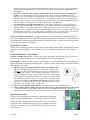
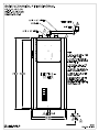
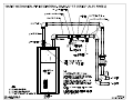
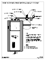
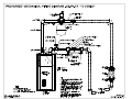
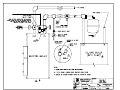
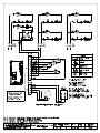
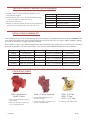
ELECTRO-BOILER TS Series INSTALLATION & OPERATING INSTRUCTIONS Model APPLICATION: EB-WO-13 EB-WO-18 EB-WO-23 EB-WO-27 This Electro-Boiler is factory equipped with WarmFlo smart controller. WarmFlo automatically regulates outlet water temperature based upon outside temperature and presetup parameters (commonly called “outdoor reset”). Primary application is any hydronic water heating system where reduced flow or radiation can cause overheat conditions (example, zones). However, if it is a mixture of large and small zones, the sudden capacity and flow changes may cause some internal timing/overtemp conditions. With the mixture of zones the zone controller ZTS-* option is highly recommended (see page 2). This series is equipped for load management interrupt and can apply to standard baseboard radiation, dual heat combinations, under floor radiant, wood boiler supplement, etc. Note: If this installation does not include dual heat standby boiler, the front panel switch must always be in the “normal” position. ACCESSORIES: Attached BL001 lists various accessory or option items which are not part of basic Electro-Boiler. Also page 3 has additional information on slab stat. Page 2 gives information on a zone control update which stages elements based upon zone capacity. Note: This product meets the requirements of the ASME Boiler and Pressure Vessel Code. Drawings: 03/19/2009 BX501 BX502 BX201 BH502 BS502 BL001 XX017 BI502 TABLE OF CONTENTS Description Page Introduction 1 System or Water Flow 2 Multiple Zones & Radiant Temperatures 2 Zone Controller 2 Room Thermostat Placement 3 Multiple Boilers 3 Two-Temperature Operation or Feature 4 Boiler/Plumbing Kit Placement 4 Installation Requirements 4 Mechanical Installation 03/19/2009 Under-Floor Radiant 6 Dual Heat 7 Electrical Hookup 8 Standby Boiler 9 Remote Display 9 Water Fill Procedure 9 Controller Setup 10 Operational Tips 12 Replacement Parts List 13 Troubleshooting/Repair Helps 13 WarmFlo Operational Information 14 BI502 INTRODUCTION With this WarmFlo configuration, the electric heating elements are automatically modulated and controlled to establish a fixed outlet water temperature. This outlet temperature is sensed by the WarmFlo controller and is controlled by outside temperature and by setup parameters. First-time or non-routine user – before attempting installation or setup of a WarmFlo product, we suggest studying the last section of this manual, Operation Information and Technology Definitions. Also, if you have not attended a WarmFlo training session, document HC320 application flowchart, and other Electro WarmFlo written material may be of assistance. Even though this WarmFlo configured unit adjusts outlet temperature independent of water flow and prevents high limiting even with marginal water flow, it is still very important that the hydronic system be correctly designed for the building, the total heat loss requirement, and proper hydronics design and installation practices. This boiler is the energy source for the water flow and radiation system. If the water flow and radiation systems are not adequate for the Btuh heat loss of the building, installing the Electro-Boiler with WarmFlo will not necessarily supply the comfort and heating for the building. Control and operate as a “cold boiler” concept. Do not, under any circumstances, simply jumper R and W and allow the temperature sensing controller to operate this Electro-Boiler as a “hot boiler”. Unless there is at least 2 GPM flow, the staging delays will cause temperature overshoot and could open up the manual reset limits. In most dual heat installations this Electro-Boiler is plumbed in series with an existing oil, gas, or wood boiler. For gas or oil, the Electro-Boiler is generally at the gas/oil outlet; but for wood, the Electro-Boiler must be on the inlet sides. The standby boiler cannot be operated as “hot boiler”. This will defeat the Electro-Boiler. Rewire as required, standby boiler is turned on from the brown wires. In the case of existing fossil fuel boiler conversions, it is assumed the expansion tank, valving, air bleeder, and circulation pump are in place, in good operating condition, and adequate for the overall system design. In the case of new installation (floor radiant or baseboard), use standard hydronics water heating practices for the necessary expansion tank, air bleeder, valving, water pump, etc., sized for the total capacity of the system. The Electro-Boiler is turned on with an “R and W” closure from the zone system wiring. 208 Volt application – the elements within the standard product are rated a 240 volts. If operating at 208, there will be approximately 25% reduced capacity. The internal transformer may or may not adequately operate the control system from a 208 source. Voltage measurements between “R” and “C” must be 22VAC or greater when the system is in the complete operational mode. True 3-phase, 208-volt, models are available in the WarmFlo series. Contact factory, models EB-WO-13-2 and EB-WO-27-2. In the case of under floor radiant heating, the basic components for the electric energy, heating system typically includes: 1. 2. 3. 4. 03/19/2009 Electric boiler itself, drawing BX501 – covered by this manual. Plumbing kit or piping material at the boiler itself – can be ordered as a kit. EB-BK-TS – shown on plumbing installation drawing BX502, pages 1 and 2. EB-PK-TS – shown on plumbing installation drawing BX502, page 3. Circulating pump – typically sized for head pressure and system flow requirement, typical catalog number EB-P2. Large pump maybe required for 23 or 27 kW. The under floor circulating tubes and manifolds – provided and manufactured by others, not covered in this manual. 1 BI502 APPROVED TUBING/PIPING When plumbing this boiler and its peripheral parts to the loop system, all plumbing parts and/or tubing must be sealed to prevent entrance of oxygen. Use only tubing or polyethylene tubing with oxygen Diffusion Barrier. SYSTEM OR WATER FLOW In order to prevent hi-limiting and assure full 20+ years parts life, the piping system/basic plumbing/circulator pump must be arranged to provide flow greater than minimum GPM shown in Table 1. If zoned system, this applies when the smallest zone is operating. NOTE: Since this is an automatic temperature sensing system, both sensors and the complete control wiring are required before using or turning on this Electro-Boiler. MODEL EB-WO-13 EB-WO-18 EB-WO-23 EB-WO-27 TABLE 1 - ELECTRO-BOILER BTUH RATING 46,000 13.5 KW 61,400 18 KW 76,800 22.5 KW 92,150 27 KW AMP 56A 75A 94A 113A GPM 2-6 2-8 2-12 2-18 MULTIPLE ZONES AND RADIANT TEMPERATURES Same water temperature all zones – in this case the system can be setup as one pump with the water circulated through the boiler and directly to a manifold containing the various zone valves. Although this model series has a built-in outlet sensing and controller mechanism for staging the elements, also consider the next section, Zone Controller. If not using zone controller, the end switches of all of the zone valves are paralleled and directly control R and W to turn on the boiler. Various water temperature requirements – if this is the case, a primary loop with mixing valve for the various zone temperature requirements is necessary. Injection pump techniques can also be used. However, usually injection pump techniques come with a controller which is designed to protect a gas boiler from cool water return. This is simply not needed and a duplication with the temp. sensing controller within this Electro-boiler and the injection pump controller will be of no benefit within the operating system. The zone valve/zone pump control strategy must be wired to provide the boiler “R and W” contact closure and the primary pump is connected to the boiler pump contacts. This assures the primary pump is active and running whenever the boiler is turned on via contact closure on “R and W”. At least one zone must be open before turning on the primary pump/Electro-Boiler. Do not design a system where the Electro-Boiler is supposed to operate as a “hot boiler” based upon its outlet sensor without the primary pump circulating water, minimum 2 GPM is required. New, improved feature – the EB-ZTS-1 zone controller priority zone now has the ability to communicate with this TS Series boiler and it will automatically switch to a low mass high water temperature (150 or 180) during zone 1, priority switch on, operation. With this feature the TS boiler can automatically take care of two temperature requirements thus eliminating the need for the technique described in the paragraph above. ZONE CONTROLLER This EB-WO series boiler controls the electric elements (modulation) based upon water temperature independent of flow; therefore, in theory, a staging zone controller is not required; however, there are three suggestions or reasons why a zone controller can simplify the installation and enhance overall performance. 1. Zone wiring and troubleshooting convenience – the addition of the zone board (fits within basic boiler cabinet) allows for easy terminal block and point to point wiring for each zone thermostat and each zone valve. 03/19/2009 2 BI502 Also there are LED’s associated with the thermostat action and the zone valve action. This greatly simplifies wiring and future troubleshooting with a neat terminal block wiring arrangement and the onboard LED’s – order EB-ZT*-1. 2. Prevents over control or false staging up and down when the temperature sensors are attempting to regulate – since Electro Industries’ zone controller also has staging “smarts”, the addition of the zone controller will provide smoother boiler temperature control. The zone board has a dial switch for each zone and the installer selects one of four zone capacity sizes. When dialing in the size closest to the zone Btu/h capacity, the zone controller “smarts” only allows the appropriate boiler stage which can handle that capacity. Also this is additive if more than one zone calls at any one time – order EB-ZT*-1. 3. Two temperature system with unbalanced zones – if the application includes zone one requiring high temperature (fin tube, air handler, etc.) and the remaining zones are radiant floor low temperature, this zone controller (EB-ZT*-1) will automatically raise the output of the high temperature zone. This is a priority arrangement, zone 1 holds off the other zones while the high temperature output is heating. If at the end of the high temperature zone there is a call on any of the low temperature zones (up to three plus slave 4), there will be a pump only function until the outlet temperature drops below the front panel dial setting. Field zone controller installation – the above mentioned zone controller board is installed within the basic cabinet. However, the zone controller board must communicate with the main TS boiler board. All units manufactured prior to approximately January 10, 2004 may need a controller program chip upgrade. Verify your unit is Ver. 6.20 or higher. ZONE CIRCULATORS The EE-5051 switching relay can be used to interface line voltage pumps with the boiler R and W control terminals, see drawing BH008. This switching relay can be combined with the above zone controller board. ROOM THERMOSTAT PLACEMENT Fin tube radiation, fan coil, etc. – heat only wall t-stat, connected to operate zone valves (see previous section) or for single zone the t-stat is connected directly to Electro-Boiler R and W. Floor radiant – comfort and proper space heating response is a direct relationship to the thermostat type and the placement of the thermostat sensing bulb. Typically an under floor heating system can be broken down into three categories. A. Energy storage, water tubing is under the concrete or within the sand base – the controlling thermostat must have a remote bulb, and this remote bulb must sense the concrete slab temperature (slab stat). Coordinated with the concrete pour, install a ¾” PVC, minimum bend radius of 7 inches, and locate at approximately center (vertical) of the concrete slab. The thermostat sensing bulb can later be pushed down this PVC conduit. If the slab is already poured without conduit for slab stat, use electronic remote sensing thermostat such as Electro Industries’ ES-24-SRO or ES-24-C-RS. These devices only require a ¼” hole drilled in the floor at some convenient location (preferably off a center wall, not within 2 feet of outside wall). B. Floor covering, medium to high insulation – use slab stat as described in paragraph A above. C. Quick response, hydronic tubing just under the concrete surface, no flooring material over the concrete – in this case, heated water can directly radiate into the room, a standard wall mount room thermostat is adequate. Mount room thermostat on an inside wall similar to most heating systems. MULTIPLE BOILERS This boiler series now includes a method for automatically staging any number of parallel-plumbed boilers. Order plug-in relay EB-C-STG5. The thermostat is connected only to the first boiler, when all stages are on for more than 5 minutes, this new plug-in relay module turns on the next boiler (R and W), and a second EB-C-STG5 could be used to turn on the third, etc. 03/19/2009 3 BI502 TWO-TEMPERATURE OPERATION OR FEATURE When using Electro’s zone controller in priority mode, the boiler system can automatically raise the outlet temperature with zone 1 calling. This is setup for default of 150° or pulling a jumper peg the high temperature value is 176°. See appropriate zone controller installation manual for details. BOILER/PLUMBING KIT PLACEMENT This model series is wall hung and the vessel must be vertical, drawing BX501. The plumbing kit items are located adjacent to the boiler housing itself as shown on drawing BX501 or BX502. For future servicing, the unit itself must be installed 20” or more above the floor, the elements are screwed in from the bottom. INFORMATION/WATER FLOW CALCULATIONS Water flow, GPM, can easily be calculated if the temperature rise across the electric boiler can be measured. The formula below can only be used when the temperature rise is stable and the boiler is not hi-limiting. In other words, verify constant current draw and stable outlet temperatures for at least 15 minutes. GPM = Volts x Amps x 3.4 500 x Temp. rise INSTALLATION REQUIREMENTS 1. All installation work must be performed by trained, qualified contractors or technicians. Electro Industries, Inc., sponsors installation and service schools to assist the installer. Visit our web site at electromn.com for upcoming service schools. WARNING ALL ELECTRICAL WIRING MUST BE IN ACCORDANCE WITH NATIONAL ELECTRIC CODE AND LOCAL ELECTRIC CODES, ORDINANCES, AND REGULATIONS. WARNING OBSERVE ELECTRIC POLARITY AND WIRING COLORS. FAILURE TO OBSERVE COULD CAUSE ELECTRIC SHOCK AND/OR DAMAGE TO THE EQUIPMENT. CAUTION This unit can only be used for its intended design as described in this manual. Any internal wiring changes, modifications to the circuit board, modifications or bypass of any controls, or installation practices not according to the details of this manual will void the product warranty, the CSA/us certification label, and manufacturer product liability. Electro Industries, Inc., cannot be held responsible for field modifications, incorrect installations, and conditions which may bypass or compromise the built-in safety features and controls. 2. This installation manual and Electro-Boiler products relate only to the addition of the Electro-Boiler to the hydronics system. The owner/ installer assumes all responsibility and/or liability associated with any needed installation of the gas/oil boiler, pump, plumbing, system design, hydronics systems 03/19/2009 4 BI502 or backup gas/oil boiler, etc. Any instructions or comments made within this manual (or factory phone assistance) relating to the gas/oil furnace are provided as comments of assistance and “helps” only. CAUTION Hazards or unsafe practices could result in property damage, product damage, severe personal injury and/or death. 3. Remember, safety is the installer’s responsibility and the installer must know this product well enough to instruct the end user on its safe use. Safety is a matter of common sense - - a matter of thinking before acting. Professional installers have training and experienced practices for handling electrical, sheet metal, and material handling processes. Use them. CLEARANCES BACK LEFT RIGHT FRONT TOP BOTTOM 03/19/2009 MINIMUM CLEARANCE FROM SUGGESTED MINIMUM COMBUSTIBLE SURFACES SERVICE CLEARANCE 0 INCH 0 MM 0 INCH 0 MM 1 INCH 25 MM 12 INCHES 305 MM 1 INCH 25 MM 6 INCHES 152 MM 1 INCH 25 MM 24 INCHES 610 MM 1 INCH 25 MM 24 INCHES 610 MM REQUIRED CLEARANCE – 16 INCHES/406 MM 5 BI502 MECHANICAL INSTALLATION – UNDER-FLOOR RADIATION CAUTION Electro Industries Inc. requires the use of dielectric isolation between the boiler vessel supply and return piping when the boiler is plumbed using copper or any other dissimilar metal. Damage to the vessel caused by galvanic corrosion voids Electro Industries’ warranty. Reference drawing BX501 1. With the typical radiant floor system, a dual heat backup boiler is uncommon. If a backup boiler is required, please reference “Mechanical Installation – Dual Heat” section. 2. Unpack the Electro-Boiler, the safety relief and pipe fittings are packed within a small carton. The safety relief is plumbed to the ¾” pipe as shown on BX501 (or may be part of other components shown on BX502, page 2). 3. The Electro-Boiler must be positioned with the vessel vertical. The water IN/OUT ports must be at the top. The unit will not function properly with the vessel in a horizontal position. NOTE: Mount at least 20 inches above the floor to allow element removal and service at the bottom. 4. The plumbing components and plumbing layout shown on drawing BX502 have been very carefully chosen and should be plumbed as shown. When following this diagram, the water fill procedure becomes very simple and almost guarantees the removal of all air or prevents air locking problems. Experienced hydronic heating installers may be able to eliminate some components but the inclusion of these components guarantees installation and initial operating success. 5. The vessel is factory constructed with a “air trap” chamber at the top of the vessel, connected to the ¾” pipe and arrangement shown on BX502, page 2. 6. The key mechanical components required include: Expansion Tank – as a closed loop hydronic heating system, a minimal expansion tank is required. This can be an air diaphragm tank as provided in the plumbing kit or a basic “empty” tank where air is compressed at the tank top. Inlet Temperature Gauge – recommended to observe the operation of the system. Air Vent – install with the pressure relief valve as shown on drawing BX502, page 2 or part of the air eliminator shown on BX502, page 3. Inline Air separator – this can be installed ahead of the pump with the expansion tank moved to this point. However, the vessel designed air trap and the piping arrangement leading to the air bleeder shown on BX502 page 2 works very well. Pressure Safety Valve – this is required and is furnished as a loose component with the boiler unit itself. Failure to install the provided, 30 PSI, pressure relief valve as shown void warranty and the CSA product listing. During purging there is a requirement to bleed out the initial air within this ¾” pipe leg by manually holding open the relief valve. Add the necessary pipe extension to the relief valve to prevent water damage on this unit or surrounding area. Gate Valve/Drain Valve – these are for servicing and easy fill purposes. Circulating Pump – depending upon system lift and system loop resistance, the proper circulating pump is required to guarantee the minimum GPM flow as specified in Table I, page 1. · Comment: Circulator pump can be in the outlet or inlet. Newer, higher quality pumps seem to work better in the “supply” line. 7. To ensure safe boiler operation adequate system pressure must be maintained. Some expansion tanks may have an integral regulator and “port” for water source hookup. 8. Depending upon water conditions, determine whether water additives are necessary. 9. Purge and fill water system. Do not allow the electric element to come on until the system is purged and you have verified proper water circulation. If the pump is needed, jumper the two orange wires in order to operate the pump directly from its own 120 volt source. 10. Purge each loop individually, one at a time. 11. Check for leaks. 03/19/2009 6 BI502 MECHANICAL INSTALLATION – DUAL HEAT CAUTION Electro Industries Inc. requires the use of dielectric isolation between the boiler vessel supply and return piping when the boiler is plumbed using copper or any other dissimilar metal. Damage to the vessel caused by galvanic corrosion voids Electro Industries’ warranty. Reference drawing BX201 1. Unpack the Electro-Boiler. The safety relief and pipe fittings are packed within a small carton. 2. In most dual heat installations this Electro-Boiler is plumbed in series with an existing oil, gas, or wood boiler. For gas or oil, the Electro-Boiler is at the gas/oil outlet; but for wood, the Electro-Boiler must be on the inlet sides. The standby boiler cannot be operated as “hot boiler”. This will defeat the Electro-Boiler. Rewire as required, standby boiler is turned on from the brown wires. 3. Standard hydronic hot water heating practices apply. This procedure assumes adequate piping size to meet the flow requirements of the specific boiler model, expansion tank, pump, zones, etc. are properly designed and installed. 4. The Electro-Boiler must be positioned with the vessel vertical. The water IN/OUT ports must be at the top. The unit will not function properly with the vessel in a horizontal position. NOTE: Mount at least 20 inches above the floor to allow element removal and service at the bottom. 5. Typically this unit is wall hung next to the existing boiler. 6. Use the ¾” pipe fittings to install the safety relief valve and air vent. Add the necessary piping to the safety relief valve so that water damages do not occur in the surrounding area. 7. Connect the “hot” water line from the fossil fuel boiler to the Electro-Boiler "inlet". Connect the Electro-Boiler "outlet" to the main feed line. When facing the Electro-Boiler vessel, the "outlet" is on the LEFT. 10. If piping contains any "U" bend, an air vent may be required at the top. 11. When possible, isolating ball valves are recommended for easy servicing. 12. To ensure safe boiler operation and prevent element damage, the system should contain a pressure regulator and an automatic water fill valve. Expansion tank may have an integral regulator and “port” for water source hookup. 13. Depending upon water conditions, determine whether water additives are necessary. 14. Purge and fill water system. Do not allow the electric element to come on until the system is purged and you have verified proper water circulation. If the pump is needed, short out the two orange wires in order to operate the pump directly from its own 120 volt source. 15. Check for leaks. 03/19/2009 7 BI502 ELECTRICAL HOOKUP Reference drawing BH502 1. 240 Volt Heating Power – route and install the proper current carrying conductors from service panel fuse or circuit breaker. See page 2 Specification Table and/or product nameplate for ratings. These models contain built-in circuit breakers and meet the requirement for local disconnect for appliances greater than 10 kW. Connection is at the circuit breaker terminals. If using single feed method, single feed bus GE breakers EM5716 (two CB)/EM5717 (three CB) or Square D breakers 5701 (two CB)/5702 (three CB) should be used. Only copper wire is allowed. CB1 is highest priority stage. 2. Grounding – copper conductor is required, size per NEC code relating to the current of each feed. 3. Circulating Pump – the terminal block (orange wires) below the circuit breakers represents a switch closure (10-amp maximum) to operate an external circulating pump motor. Voltage for the pump must come from a separate source. The pump is controlled as a direct function of the R and W input. If this is connected with a standby boiler, generally the assumption is series plumbing with the single pump. In this case, the R and W function will operate the pump whether in electric or standby mode. If a standby boiler installation has parallel plumbing with two pumps, field wiring and controls will be necessary to properly operate (and typically check valve isolate) the standby boiler self-contained pump from the system pump controlled by these two terminal screws. 4. Operating Thermostat – two types can be used. Connection is at the control board bottom. Standard Mechanical – connect to “R” and “W”, bottom right. Set thermostat internal heat anticipator to 0.2. Electro-Stat – (ES-24-C-RS or ES-24-SRO) 3 wire connection required. R to R, W to W, C to common The Electro-Stat remote sensor can be extended as required. This is a three wire cable, cut and splice, up to 50 feet. Use only stranded wire, shielded cable is not required. Comment: If zone valve or zone pumps see appropriate sections. 5. Load Management Interrupt Control – this Electro-Boiler series has been pre-wired and designed for an external utility load management receiver connection. The control board lower left BLU and BLU/WHT wires represent the two contact points, extend these wires to the utility load control device. As shipped, this unit is only equipped for off-peak = N.C. logic. If reversed logic is required, contact the factory for modification. Optional – if load management is not used, simply keep the two blue wires shorted. Optional – if the power company disconnects 240V for load control, please reference BH029 for special wiring requirements. 6. Outdoor Sensor (OT) – (EB-WO models only) the loose OT sensor bracket/probe needs to sense true outdoor temperature. Mount on an outside wall position that will represent the most accurate outdoor temperature. If possible shade from direct sun rays. 7. Zone Valves or Zone Pumps – see page 2 for zone controller options. 03/19/2009 8 BI502 WARNING: The end switches from the zone valves must be an isolated contact with no voltage present on these wires or screw terminals. This is very important to make sure there isn’t any interference or feedback between the transformer operating the zone valve system and the transformer within this Electro-Boiler product. Once this has been determined, all end switches are simply paralleled with the two wires going to “R” and “W”. 8. If this is a dual heat application with standby boiler, the 2 brown wires connect to the standby boiler R and W or T and T. These 2 brown wires represent a contact closure to activate the standby boiler during load control or when the front panel switch is in the “standby” position. 9. Remote Display – an optional remote display (4-wire stat cable) can be added, call factory for details. WATER ADDITIVES 1. Unless the source water is unusually poor and/or rust elements, additives are not required. It is recommended the water source as shown on drawing BX502 comes through the household water softener or use distilled water. 2. Impurities within a closed loop hydronics boiler are considerably less damaging than the typical domestic water heater. In a closed loop electric boiler, the water impurities “boil out” and the system essentially makes its own pure water. As a closed system, this “pure water” becomes the operating mode. In the case of domestic water tank, there is always new water entering with new impurities. 3. However, if additives are required, use the recommendations and source from your local professional plumber, specializing in hydronics heating systems. WATER FILL PROCEDURE The following procedure applies to non-glycol or antifreeze and prepackaged plumbing kit and/or when the system is plumbed exactly as shown on drawing BX502. Caution: If the building supply pressure is connected directly to supply water ball valve without pressure reducing regulator, user needs to make sure the pressure within the boiler loop does not exceed 30 PSI. Careful control of the supply water ball valve opening can take care of this. Also at steps 6 and 10, use caution to make sure the building water supply pressure does not “spike” the system. 1. Connect the temporary household water supply source (probably hose connection) to the "water supply connection" input. NOTE: If water supply connection is permanent, some local building codes may require special anti-siphon check valve, RPZ check valve, or equivalent between the boiler fill regulator and the domestic water source or the city water connection. 2. Connect a drain hose to hose bib, "drain valve". 3. Open "drain valve" and close "inlet gate valve" (between drain valve and boiler inlet). 4. Verify “top gate valve” is open. 5. Do not apply 240 heating power during water fill sequence. 6. Open “water supply valve” and open household water supply source. 7. Allow system to circulate, discharging through drain valve, for at least 15 minutes. 8. Put your ear against the metal pipe and listen for air bubbles. If the water flow is consistent and quiet, the system is probably purged and water filled. 9. Close the "drain valve". Open the "inlet gate valve". 10. The cold system pressure at the gauge should be approximately 10 to 14 PSI. 03/19/2009 9 BI502 11. Close “water supply valve” and disconnect water supply. 12. Optional – energize circulating pump during this fill operation. The water pressure from the household system and as plumbed should typically flow through the circulating pump without the pump running. COMMENT: Purge one loop at a time. CONTROLLER SETUP The front panel contains a red temperature select “knob” with two selection ranges – high mass/low mass. Certain internal sequence timings and operating stage differentials adjust themselves according to the switch position. The primary noticeable difference is the supply water start point. The front panel temperature selection number coincides to the curves below. This temperature value shown on the front decal (see Table 1, next page) is actually the supply water at 0° outside. Each curve starts from a base temp point (high mass – 90°/low mass – 120°). This is the beginning ramp-up point from typical 67° outside. NOTE: The customary definition of “outdoor reset” is basically opposite to this Electro Industries’ WarmFlo concept. In the case of outdoor reset you set the maximum or worst condition operating supply temperature. As it warms up outside the supply temperature is decreased downward from that point. In the case of Electro Industries’ WarmFlo, we begin at a minimum or comfort level supply temperature and ramp upward to the higher temperature as it gets colder outside. The boiler products simply use 0° as a reference and as a point to set on the dial. The curve continues to provide higher supply temperature at temperatures below 0° F, as shown. Field base temp selection – shown in Figure 1 and Figure 2 are the factory default values. With Electro Industries’ WarmFlo Analyzer model WF-ANZ7 and newer or PC software version 4.1* or newer, the base temp start point can be changed. However the EB-WO-** must also have 6.23 or newer chip. The range is shown in Figure 1 and Figure 2. The 0° F reference point, as set on the front dial, remains the same; the slope of the curve lines simply shifts to a new 67° F outside point. 03/19/2009 10 BI502 Circulator pump mode – as factory set, the circulator pump is controlled directly from the “W” input terminal. In this setup the circulator pump continues during load control interrupt (or optional remote standby switch). There is a provision within the controller board (inside) to allow the circulator pump to not operate during load control interrupt. On the inside control board, just above the two bottom terminal blocks, is a small pin jumper arrangement. The black “device” sets up the pump mode. Just below this pin jumper arrangement are W and L lettering. When the two pin shorting device is in the W position, the pump is a direct function of R to W input. When the two pin jumper is in the L position, the pump is interrupted during a load control. WARNING: This shorting device must be in one of the two positions for the circulator pump to properly operate. 03/19/2009 11 BI502 OPERATIONAL TIPS Normal/Standby Switch If this system does not have a standby operating (gas or oil) boiler, this switch must always be in the “normal” position. To activate standby boiler, simply position front panel switch to “standby”. Monitor Lights, Front Panel HI-LIMIT, red – this will only illuminate when the vessel hi-limit opens due to excessive high water temperature. This hi-limit is self resetting. PWR ON, green – basically this is illuminated at all times. It represents 24-volt power source, good fuse, controller logic is operational, and a good outlet sensor. If the outlet sensor is inoperative, incorrectly wired, or malfunctioning; this green monitor LED should be in the blinking or pulsing mode (see page 11). EL MODE, amber – when illuminated the system is in the electric mode. If it is not illuminated the utility load control receiver is in the interrupt or on-peak mode. If there is an optional or remote standby switch, the status of the standby switch is also monitored by this amber LED. HEAT ON, red – indicates a remote switch closure (t-stat or zoning end switch) is closed between terminals R and W. Inside Controller Board STAGES, red – these four LED’s indicate which electric element stages are on and active. Manual Reset, Hi-Limit At the top of the vessel there will be either two or three surface mount hi-limits preset at 205° F. There is no light indicator associated with these safety hi-limits. Also these 205° F safety limits break the L2 current carrying 240-volt wire going to the elements. Reset involves locating a small shiny lever or metal tab protruding on the side of the black safety limit base. This small tab is pressed inward approximately 1/8” to “snap in” the contacts. Safety caution – the wires and screws have 240-volt potential and can be dangerous. Turn off circuit breakers before investigating or attempting to reset the 205° F safety limits. Internal Fuse The fuse on the controller board protects the transformer secondary, external items connected to “R”, and the circuit board itself. Replace with 2-amp fast blow, AGC2 or equivalent. Stat Heat Anticipator - If it is a mechanical stat, verify heat anticipator has been set at Ø.2 (non-zone system). System Pressure The side press/temp. gauge should be at approximately 10 to 16 PSI at room temperature water and should not rise more than approximately 4 PSI at the operating or hot water temperature. If the pressure change is more than approximately 4 PSI, the expansion tank is too small or there is a problem with the expansion tank piping, expansion tank itself. Cold slab, outdoor reset and temperature sensing prevent full boiler on – by adding a temporary jumper between the lower W screw terminal and the upper left “E” tab, all temperature sensing functions are bypassed and the control board will step in all the stages. Caution: This jumper shall not be a permanent function, jumper needs to be removed after slab is approaching normal temperature. 03/19/2009 12 BI502 Replacement Parts @WFS3 @WFS255612 @EBSTU5623 UFUSE0440 4038 5127 5535 5537 5453 5456A 5640 5639 5652 5650 5520 5541 Water sensor, 3 ft. Outdoor sensor (OT) Controller, temp. sensing 2-amp fuse, fast blow (AGC2) Triac switch module Heating relay Safety hi-limit, manual, 205° First hi-limit, auto-reset, 180° Relief valve, 30 PSIG Gauge press/temp. 60A GE circuit breaker 30A GE circuit breaker 60A SQ D circuit breaker 30A SQ D circuit breaker Electric element, 240, 4.5 kW Transformer, 24V, 40VA TROUBLESHOOTING/REPAIR HELPS 1. This WarmFlo controller contains several interference suppression components, but as an electronic logic product, unpredictable and unusual transients or interference may sometimes cause strange results. If the WarmFlo controller is “acting strange”, one immediate step would be power down reset. Simply turn off boiler power or breaker number 1, when the green LED goes out, count to 1Ø, and re-energize power supply. 2. Inoperative temperature sensor, if the internal program can detect a bad sensor (shorted, open wire, etc. – not necessarily bad value) the front panel green LED will be pulsing. By checking the pulsing pattern, the appropriate sensor can be identified. - OT sensor – 100 ms blink every second - ST sensor – two, 100 ms blinks every second - Both bad – ½ second on, ½ second off, alternating 3. The temperature sensor can be further evaluated with diagnostic program from standard PC or Analyzer software. This includes the ability to “fool” the sensor or set in an offset for various troubleshooting purposes. This software disk comes with a special cable needed for PC or Analyzer hookup. - ET-SOFT-TS – PC software disk and cable - ET-SOFT-TSP – Palm software disk and cable 4. The terminal blocks for control wire hook-up are designed for a wire insertion and screw clamp down. If there is no wire connected and the screw is loose, the screw may not necessarily make a good electrical contact to the inside components. Example - If you are jumpering the thermostat terminals without thermostat wire connection or if you are attempting to measure voltage on the screw head, you may get erroneous or unpredictable results if the screw is not tightened down. 5. The outdoor sensor (OT) must be sensing the actual outside temperature for this controller to correctly operate. Do not simply leave the outdoor sensor “hang in the room” and attempt to run this system. 6. Temperature sensing bypass – the inside control board, left side, contains a “E” tab which can be used to directly step in the heating stages and in essence bypass the temperature sensing and control functions. The “E” tab has the highest priority and overrides all temperature sensor functions. In other words, when jumpering from W to E all four stages are hard on. Note: Verify pump is operating prior to using the E terminal. Since activating this E terminal causes full electric element output, this function should only be used to verify all stages or troubleshoot proper 24Ø current at each element. 03/19/2009 13 BI502 7. Use general heating system logic information and basic understanding of the terminal block wiring functions measure various voltage points to determine proper operation. 8. Acquiring the PC software or Palm with serial port hookup cable is a positive tool for understanding and troubleshooting the WarmFlo controller. Either test set device can display all temperatures, real time evaluation of WarmFlo functions and provide temperature offsets for assimilating winter conditions. Sensor Temperature Calibration - Both remote sensors are digital electronic and factory calibrated. Normally these do not require field calibration or verification. However, if sensor temperature error is determined, there are two field calibration techniques. Proceed with extreme caution. 1. The outdoor sensor (OT) can be calibrated with ice (32F). This is not a checking temperature situation. If you proceed with this function, the sensor automatically goes to 32F. Notice a small push button next to the sensor terminal block, with the sensor at 32F, push and hold for approximately ten seconds. When the green LED next to the fuse “blinks” at you, release and now the outdoor sensor is set at 32F. 2. Use PC or Palm software to calibrate sensor. See other paragraphs. OPERATIONAL INFORMATION In order for the installer to completely understand the WF II functions and operational sequence it is recommended to thoroughly read and understand the information below. This knowledge can help in determining settings that can be set according to the end customers needs. PC software (ET-SOFT-TS) or Analyzer (WF-ANZ*) – both now have provisions for the following setup or reprogramming functions. - STANDBY RESET – allows disable of 5-minute/80° reset SOT E time, or disable – all stages on (DT flat) Stage disable temperature – 1, 2, 3, 4 * *Applies mainly to EBWO, for EBWA OT function is disabled. Warning, field reprogramming – within WarmFlo II internal logic and non-volatile memory, it can detect whether it is operating from one of the above factory pre-programmed chips or if it has been modified (reprogrammed) with PC software or Handheld. Once the user or field technician has downloaded (save), from that time forward the WarmFlo II physical control board is no longer governed by the above table, or the chip code written on the plug-in chip, etc. In other words, power up/power down, reset, or removing and re-plugging the chip does not affect any altered reprogrammed functions. It is smart enough to know it is no longer the original chip and that specific physical board, from this time forward, must be under the control of the PC software/Palm. Normal Heating Operation – whenever the WarmFlo screw terminal “W” is at 24 volt (with reference to “C”), the WarmFlo controller begins turning on the elements and automatically controls the water temperature as sampled by the ST sensor. However, if added heat is not required, no element power is used. Depending upon the Electro-Boiler model, there will be various electrical stages, all under the control of WarmFlo. Except for the first 4.5 kW element, the remaining stages operate as steps 2, 3, and 4 from the WarmFlo controller. Step 1 (first 4.5 kW) is pulse modulated through the triac (approximate 1Ø second cycle) based upon the WarmFlo controller automatic requirement. Steps 2, 3, and 4 are turned on and off with relays. However, steps 2, 3, and 4 are only used when required by the WarmFlo water temperature calculations. Stage 1 may not necessarily remain at 100%, but is modulated downward to meet the requirements of the water sensor, etc. 03/19/2009 14 BI502 The time between stage turn on depends upon where the controller logic memory was after the last thermostat call or following a power up reset condition. The longest time between staging is from the power up condition because the logic does not have a history of previous thermostat calls. Once the history of several thermostat calls has been established within memory, it automatically returns to the last active stages, with an approximate 5 seconds between stage turn on. However, during power up the logic needs to search a number of times before it finally declares the next stage. In this power up reset situation (with the call for heat) the timing is: - Stage 1 – 90 sec. full on - If no stage 1 modulation (pulsing), 2 min. - Stage 2 on - If stage 2 is on with no stage 1 modulation (pulsing), 4 min. - Stage 3 on - If stage 3 is on with no stage 2 modulation (pulsing), 4 min. - Stage 4 on Note: The above is worst case and high mass mode. For low mass it is faster, etc. A clamp-on amp meter at the service input can be used to “visualize” the stage 1 modulation and/or stage 2, 3, and 4 functions. Staging disables at specified outdoor temperatures – the factory setup allows all four stages to come on at outdoor temperatures below 90° F. Using download reprogramming, an outdoor temperature can be set for each stage allowing the disable of specific stages above the preset temperature. Delay, transfer from standby to electric – if the unit was operating in SB for more than 1 minute, the follow-up transfer back to electric engages a 2-minute delay before any of the electric stages are activated. The pump will react to the call for heat, but the elements will stay off for 2 minutes in order for the pump to cool down the standby boiler vessel. SB (Gas) 5-Minute Safety – when in the standby mode (see previous section) there is now a 5-minute timer which begins at each heat call. If after the 5 minutes the ST sensor is less than 80°, the logic board itself goes into an automatic reset and restart. This simply means it attempts to begin the heat cycle using electric in case the boiler did not ignite or “out of gas”. However, if it is in the SB mode because of Load Control it will still remain SB and try the gas boiler again. The system will never go back to electric if you have a Load Control on-peak. - This can be disabled, see previous PC Software section. EB-WO VERSUS EB-WA COMPARISON The only difference is the outdoor sensor capability and programming associated with outdoor sensing outlet temperature ramping or preset value. Both model series use plug-in chip Version 6.2*, but specifies 4-digit code for this temperature sensing programming. Model Series EB-WO EB-WA 03/19/2009 Outdoor Sensor (OT) Required, connected Not required 6.2* Code EB-WO EB-WA 15 Front Panel Decal UAI839 UAI843 Install Manual BI502 BI506 BI502 BOILER ACCESSORIES ZONE CONTROLLER This will simplify your wiring and make zoning applications much easier. In addition, enhanced communicating features have the ability to stage the electric boiler based upon the connected zone capacity. Pumps, Actuators, Valves Standard Features EB-ZTA-1 - install within boiler cabinet EB-ZEA-1 - with enclosure and 40VA transformer EB-ZEA-2 - add additional 4, enclosure and 40VA • Utility load control • Terminal block wiring, visual wiring layout • Indicator lights showing zone operation Pumps • 24-volt, 40VA transformer 120/208/240 connection Zone Valves EB-Z2P - two pumps with priority and dual temp. EB-ZTS-1 - install within boiler cabinet, encl. option EB-ZTS-2 - add additional 4, enclosure and 40VA • Fuse protection • Priority option • Dual temperature operation • Applies to digital or standard thermostats • Dial switch, select each zone capacity All Others EB-ZXA-1 - universal, pumps or valves, non-communicating, for any boiler EB-ZS-4 - automatic staging system for Brand X boilers or dual EB-R, -L, -E Series EB-ZC-4 - wiring and convenience interface, isolated boiler end switch EB-5415A - low cost, 2 or 3 zones, sheds one boiler stage (Mini-Boiler enhancement) SLAB STAT Sensing and controlling the system based upon radiant floor surface temperature or the concrete mass has very positive benefits. Radiant floor air stat in the same area as a forced air roomstat presents serious control problems. A remote sensing slab stat for the radiant floor removes this issue. Remote sensing slab stat is required for storage applications. ES-24-BR SWITCHING RELAY - EE-5051 This DPDT 24-volt switching relay provides a convenient solution to any AC or DC application. MULTI-BOILER - EB-C-STG5 Electrically connects between 2nd and 3rd, 3rd and 4th, etc. OTHER OPTIONS • • • • Ideal for zone pumps 24V coil 120V, 10A, contact sets Easy to wire and nicely packaged SOT-1 5701 5702 EB-S-SB WF-ANZ* Switchover to standby, total run time Single feed bus for 2 CB’s (SQ-D CB) Single feed bus for 3 CB’s (SQ-D CB) Dual boiler option for EB-S Series WarmFlo Analyzer, now applicable to WO and WA Series Specifications subject to change without notice, all rights reserved. TWO SUPPLY WATER TEMPERATURE REQUIREMENT • Handled as the priority zone on multi-zone (EB-ZEA-1) or two pump (EB-Z2P) controllers • Priority switch on, zone 1 active - TS boiler automatically changes to 150° (or selection 176°) supply water setting • • All other zones are held off With zone 1 satisfied or 60-minute timeout, the boiler automatically returns to the preset temperature and reacts to the other zones Low Temp High Temp Radiant, slab Radiant, staple up Radiant, slab Baseboard Radiant, slab Fan coil Radiant, slab Water heater, side arm Radiant, slab Hanging unit heater (garage, shop, etc.) INSTALLATION PLUMBING KITS These installation kits provide the critical plumbing components needed for easy installation of the Electro-Boiler. In addition to the items shown in the matrix below, each kit includes all necessary ball valves, drain valve, tees, elbows, nipples, bushings, couplings, etc. for direct connection to circulator pump and/or manifold. Electro Industries’ boilers come standard equipped with outlet temperature/pressure gauge, pressure relief safety valve, and when applicable, the WarmFloTM electronic control sensors. These kits provide the additional components for easy installation: Model Application Return Gauge EMB-BK All EMB Series EMB-PK All EMB Series EB-PK-M EB-MS, -MA, -MO Series EB-BK-TS EB-S, -WA, -WO Series EB-PK-TS EB-S, -WA, -WO Series Expansion Tank Air Vent 2.1 gal. (7.9 L), 40,000 Btu/h Basic float type 2.1 gal. (7.9 L), 40,000 Btu/h Enhanced air separator, EAS 4.5 gal. (17 L), 135,000 Btu/h Enhanced air separator, EAS 4.5 gal. (17 L), 135,000 Btu/h Basic float type 4.5 gal. (17 L), 135,000 Btu/h Enhanced air separator, EAS CIRCULATING PUMPS 5585 - Mini-Boiler & 10 kW TS Series • 120V, 1/25 HP, maintenance-free wet rotor circulator • Pump curve example - 5 GPM (19 L) @ 11 ft. of head (32.9 kPa) 07/24/2007 5586 - TS Series, Standard • 120V, 1/6 HP, maintenance-free oil lubricated circulator • Pump curve example - 10 GPM (37.8 L) @ 20 ft. of head (50.8 kPa) 5578 - 3/4” Pipe 5582 - 1” Pipe 5579 - 1-1/4” Pipe • Two flanges, with isolation valve BL001 Electro Industries, Inc. Limited Product Warranty Effective February 5, 2009 Electro Industries, Inc. warrants to the original owner, at the original installation site, for a period of two (2) years from date of installation, that the product and product parts manufactured by Electro Industries are free from manufacturing defects in materials and workmanship, when used under normal conditions and when such product has not been modified or changed in any manner after leaving the plant of Electro Industries. If any product or product parts manufactured by Electro Industries are found to have manufacturing defects in materials or workmanship, such will be repaired or replaced by Electro Industries. Electro Industries shall have the opportunity to directly, or through its authorized representative, examine and inspect the alleged defective product or product parts. Electro Industries may request that the materials be returned to Electro Industries at the owner’s expense for factory inspection. The determination as to whether product or product parts shall be repaired, or in the alternative replaced, shall be made by Electro Industries or its authorized representative. Electro Industries will cover reasonable labor costs to repair defective product or product parts for ninety (90) days after installation. TWENTY YEAR (20) LIMITED WARRANTY ON BOILER ELEMENTS AND VESSELS Electro Industries, Inc. warrants that the boiler elements and vessels of its products are free from defects in materials and workmanship through the twentieth year following date of installation. If any boiler elements or vessels are found to have a manufacturing defect in materials or workmanship, Electro Industries will replace them. TWENTY YEAR (20) LIMITED WARRANTY ON SPIN FIN ELEMENTS Electro Industries, Inc. warrants that the spin fin elements of its products are free from defects in materials and workmanship through the twentieth year following date of installation. If any spin fin elements are found to have a manufacturing defect in materials or workmanship, Electro Industries will replace them. FIVE YEAR (5) LIMITED WARRANTY ON OPEN WIRE ELEMENTS Electro Industries, Inc. warrants that the open wire elements of its products are free from defects in materials and workmanship through the fifth year following date of installation. If any open wire elements are found to have a manufacturing defect in materials or workmanship, Electro Industries will replace them. Page 1 of 2 XX017 THESE WARRANTIES DO NOT COVER: 1. Costs for labor for removal and reinstallation of an alleged defective product or product parts, transportation to Electro Industries, and any other materials necessary to perform the exchange, except as stated in this warranty. Replacement material will be invoiced to the distributor in the usual manner and will be subject to adjustment upon verification of defect. 2. Any product that has been damaged as a result of being improperly serviced or operated, including, but not limited to, the following: operated with insufficient water or airflow, allowed to freeze, subjected to flood conditions, subjected to improper voltages or power supplies, operated with airflow or water conditions and/or fuels or additives which cause unusual deposits or corrosion in or on the product, chemical or galvanic erosion, improper maintenance or subject to any other abuse or negligence. 3. Any product that has been damaged as a result of natural disasters, including, but not limited to, the following: lightning, fire, earthquake, hurricanes, tornadoes or floods. 4. Any product that has been damaged as a result of shipment or handling by the freight carrier. It is the receiver’s responsibility to claim and process freight damage with the carrier. 5. Any product that has been defaced, abused, or suffered unusual wear and tear as determined by Electro Industries or its authorized representative. 6. Workmanship of any installer of the product. This warranty does not assume any liability of any nature for unsatisfactory performance caused by improper installation. 7. Transportation charges for any replacement part or component, service calls, normal maintenance; replacement of fuses, filters, refrigerant, etc. CONDITIONS AND LIMITATIONS: 1. If at the time of a request for service the original owner cannot provide an original sales receipt or a warranty card registration then the warranty period for the product will have deemed to begin thirty (30) days after the date of manufacture and NOT the date of installation. 2. The product must have been sold and installed by a licensed electrical contractor, a licensed plumbing contractor, or a licensed heating contractor. 3. The application and installation of the product must be in compliance with Electro Industries’ specifications as stated in the installation and instruction manual, and all state and federal codes and statutes. If not, the warranty will be null and void. 4. The purchaser shall have maintained the product in accordance with the manual that accompanies the unit. Annually, a qualified and licensed contractor must inspect the product to assure it is in proper working condition. 5. All related heating components must be maintained in good operating condition. 6. All lines must be checked to confirm that all condensation drains properly from the unit. 7. Replacement of a product or product part under this limited warranty does not extend the warranty term or period. 8. Replacement product parts are warranted to be free from defects in material and workmanship for ninety (90) days from the date of installation. All exclusions, conditions, and limitations expressed in this warranty apply. 9. Before warranty claims will be honored, Electro Industries shall have the opportunity to directly, or through its authorized representative, examine and inspect the alleged defective product or product parts. Remedies under this warranty are limited to repairing or replacing alleged defective product or product parts. The decision whether to repair or, in the alternative replace, products or product parts shall be made by Electro Industries or its authorized representative. THESE WARRANTIES DO NOT EXTEND TO ANYONE EXCEPT THE ORIGINAL PURCHASER AT RETAIL AND ONLY WHEN THE PRODUCT IS IN THE ORIGINAL INSTALLATION SITE. THE REMEDIES SET FORTH HEREIN ARE EXCLUSIVE. ALL IMPLIED WARRANTIES, INCLUDING WARRANTIES OF MERCHANTABILITY AND FITNESS FOR A PARTICULAR PURPOSE, ARE HEREBY DISCLAIMED WITH RESPECT TO ALL PURCHASERS OR OWNERS. ELECTRO INDUSTRIES, INC. IS NOT BOUND BY PROMISES MADE BY OTHERS BEYOND THE TERMS OF THESE WARRANTIES. FAILURE TO RETURN THE WARRANTY CARD SHALL HAVE NO EFFECT ON THE DISCLAIMER OF THESE IMPLIED WARRANTIES. ALL EXPRESS WARRANTIES SHALL BE LIMITED TO THE DURATION OF THIS EXPRESS LIMITED WARRANTIES SET FORTH HEREIN AND EXCLUDE ANY LIABILITY FOR CONSEQUENTIAL OR INCIDENTAL DAMAGES RESULTING FROM THE BREACH THEREOF. SOME STATES DO NOT ALLOW THE EXCLUSION OR LIMITATION OF INCIDENTAL OR CONSEQUENTIAL DAMAGES, SO THE ABOVE LIMITATIONS OR EXCLUSIONS MAY NOT APPLY. PRODUCTS OR PARTS OF OTHER MANUFACTURERS ATTACHED ARE SPECIFICALLY EXCLUDED FROM THE WARRANTY. THIS WARRANTY GIVES YOU SPECIFIC LEGAL RIGHTS, AND YOU MAY HAVE OTHER RIGHTS WHICH VARY UNDER THE LAWS OF EACH STATE. IF ANY PROVISION OF THIS WARRANTY IS PROHIBITED OR INVALID UNDER APPLICABLE STATE LAW, THAT PROVISION SHALL BE INEFFECTIVE TO THE EXTENT OF THE PROHIBITION OR INVALIDITY WITHOUT INVALIDATING THE REMAINDER OF THE AFFECTED PROVISION OR THE OTHER PROVISIONS OF THIS WARRANTY. Page 2 of 2 XX017