1
Crestron 3-Series Control Systems
Reference Guide
A portion of the code in this product is covered by the Microsoft® Public License (Ms-PL), which can be found at www.microsoft.com/opensource/licenses.mspx.
This device includes an aggregation of separate independent works that are each generally copyrighted by Crestron Electronics, Inc., with all rights
reserved. One of those independent works, Linux Bridge Project, is copyrighted under the GNU GENERAL PUBLIC LICENSE, Version2,
reproduced in “GNU General Public License” on page 78, where the corresponding source code is available at: ftp://ftp.crestron.com/gpl.
The specific patents that cover Crestron products are listed at patents.crestron.com/.
Crestron, the Crestron logo, 3-Series, 3-Series Control System, Core 3, Core 3 OS, Core 3 UI, Cresnet, Crestron Mobile Pro, Crestron Toolbox, e-Control, Fusion RV,
VisionTools, and VT Pro-e are either trademarks or registered trademarks of Crestron Electronics, Inc. in the United States and/or other countries. BACnet is either a
trademark or registered trademark of American Society of Heating, Refrigerating and Air-Conditioning Engineers, Inc. in the United States and/or other countries.
iPad and iPhone are either trademarks or registered trademarks of Apple, Inc. in the United States and/or other countries. Blu-ray Disc is a trademark or registered
trademark of the Blu-ray Disc Association (BDA) in the United States and/or other countries. Android is either a trademark or registered trademark of Google, Inc. in
the United States and/or other countries. Microsoft and Windows are either trademarks or registered trademarks of Microsoft Corporation in the United States and/or
other countries. Other trademarks, registered trademarks and trade names may be used in this document to refer to either the entities claiming the marks and names or
their products. Crestron disclaims any proprietary interest in the marks and names of others. Crestron is not responsible for errors in typography or photography.
This document was written by the Technical Publications department at Crestron.
©2013 Crestron Electronics, Inc.
Crestron 3-Series Control Systems
Reference Guide
Contents
3-Series Control Systems
1
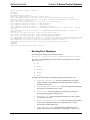
Introduction ............................................................................................................................... 1
Features and Functions ................................................................................................ 1
Core 3 OS .................................................................................................................... 2
Modular Programming Architecture ........................................................................... 2
Robust Ethernet and IP Control ................................................................................... 2
e-Control Remote Access ............................................................................................ 2
Crestron Fusion and SNMP ......................................................................................... 3
Cresnet ......................................................................................................................... 3
Onboard Control Ports................................................................................................. 3
BACnet/IP ................................................................................................................... 3
Dedicated Control Subnet (AV3, PRO3, and CP3N only) .......................................... 3
Programming Tools & Utilities ................................................................................................. 4
SIMPL Windows ......................................................................................................... 4
VisionTools Pro-e........................................................................................................ 4
Crestron Toolbox ......................................................................................................... 4
Establishing Communications with the Control System ............................................................ 6
USB Connection .......................................................................................................... 6
TCP/IP Connection ...................................................................................................... 9
Troubleshooting Communications ........................................................................................... 12
3-Series Console Commands ................................................................................................... 13
Introduction ............................................................................................................... 13
SIMPL Windows Symbols ........................................................................................ 13
Command Groups...................................................................................................... 16
3-Series Memory & Directory Structure.................................................................................. 17
Introduction ............................................................................................................... 17
Running Programs from External Storage ................................................................. 19
3-Series Control System Error Messages ................................................................................ 21
Introduction ............................................................................................................... 21
Error Levels ............................................................................................................... 21
Error Format .............................................................................................................. 21
Viewing Error Messages with Error Log Function in Crestron Toolbox .................. 22
Viewing Error Messages with Text Console in Crestron Toolbox ............................ 23
Reading Error Messages ............................................................................................ 24
Passthrough Mode ................................................................................................................... 26
Control Subnet ......................................................................................................................... 28
Master-Slave Mode .................................................................................................................. 30
Introduction ............................................................................................................... 30
Definitions ................................................................................................................. 30
Differences from the 2-Series Control Systems ........................................................ 31
Functional Behavior .................................................................................................. 31
Master / Slave Console Commands ........................................................................... 32
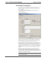
Dynamic Host Configuration Protocol (DHCP) ...................................................................... 34
Introduction ............................................................................................................... 34
Windows DHCP/DNS Server Configuration ............................................................ 34
Reference Guide – DOC. 7150A
Contents • i
Reference Guide
Crestron 3-Series Control Systems
Control System Configuration ................................................................................... 35
Secure Sockets Layer (SSL) .................................................................................................... 37
Introduction ............................................................................................................... 37
SSL Configuration ..................................................................................................... 39
Authentication.......................................................................................................................... 45
User and Group commands ....................................................................................... 45
Password Commands For Local Users ...................................................................... 48
Authentication On/Off Command ............................................................................. 49
LOGOFF Command .................................................................................................. 49
SUDO Command ...................................................................................................... 49
Audit Log Commands ............................................................................................... 50
User Access Level ..................................................................................................... 51
Local User Logon ...................................................................................................... 51
Active Directory User Logon .................................................................................... 51
Logon Session Timed Out ......................................................................................... 52
Web Server Authentication ........................................................................................ 53
Compiling and Uploading a Program ...................................................................................... 54
Compiling a Program in SIMPL Windows ............................................................... 54
Uploading a SIMPL Windows Program .................................................................... 54
IP Tables .................................................................................................................... 56
Creating the Default IP Table from SIMPL Windows .............................................. 57
Creating and Modifying IP Tables with Crestron Toolbox ....................................... 58
Running Multiple Programs..................................................................................................... 61
Device Registration Considerations .......................................................................... 61
Intra-EISC (Ethernet Intersystems Communications) Devices ................................. 62
Uploading Touch Screen Projects ............................................................................................ 63
Updating Firmware and the Operating System ........................................................................ 66
SIMPL Debugger ..................................................................................................................... 69
Using SIMPL Debugger ............................................................................................ 69
Incoming Data ........................................................................................................... 69
Status Window .......................................................................................................... 70
Trace Window ........................................................................................................... 72
Network Analyzer .................................................................................................................... 73
Support Information................................................................................................................. 74
Frequently Asked Questions (FAQs) ........................................................................ 74
Watchdog Protection ................................................................................................. 75
Further Inquiries ........................................................................................................ 76
Future Updates .......................................................................................................... 76
Return and Warranty Policies .................................................................................................. 77
Merchandise Returns / Repair Service ...................................................................... 77
Crestron Limited Warranty........................................................................................ 77
GNU General Public License .................................................................................................. 78
ii • Contents
Reference Guide – DOC. 7150A Reference Guide: 3-Series Control Systems
Crestron 3-Series Control Systems
Reference Guide
3-Series Control Systems
Introduction
The Crestron® 3-Series Control System® presents a new benchmark in control
system technology. Featuring the Core 3 OS™ control engine, the 3-Series Control
System forms the core of any modern networked home or commercial building,
managing and integrating all the disparate technologies throughout the facility to
make life easier, greener, more productive, and more enjoyable.
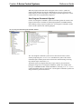
Features and Functions
•
•
•
•
•
•
•
•
•
•
•
•
•
•
•
•
•
•
•
•
Reference Guide – DOC. 7150A
Next generation control system
Core 3 OS is substantially faster and more powerful than other control
systems
Exclusive modular programming architecture
Vector floating point coprocessor
Onboard RAM & flash memory
Expandable storage
High speed USB 2.0 host port
Industry standard Ethernet and Cresnet® wired communications
Control Subnet provides a dedicated local network for Crestron devices
(not available on all devices)
Supports Core 3 UI™ XPanel web-based remote control
Supports Crestron Mobile® control apps for iPhone®, iPad®, and
Android™
Supports Crestron Fusion and SNMP remote management
Native BACnet®/IP support
Installer setup via Crestron Toolbox™ or Internet Explorer®
Backward compatible to run existing SIMPL programs
Full Unicode (multi-language) support
Increased network throughput and security
Secure access though Active Directory integration or standalone
account management
IIS v.6.0 web server
IPv6 ready
3-Series Control Systems • 1
Crestron 3-Series Control Systems
Reference Guide
Core 3 OS
Today’s commercial buildings and custom homes comprise more technology than
ever before, and all these systems need to be networked, managed, and controlled in
fundamentally new ways. The IP-based Core 3® platform is engineered from the
ground up to deliver a network-grade server appliance capable of faithfully handling
everything from boardroom AV and home theater control to total building
management.
Core 3 OS embodies a distinctively robust, dynamic, and secure platform to elevate
system designs to higher levels of performance and reliability. Compared to other
control systems, Core 3 OS provides a pronounced increase in processing power and
speed with more memory, rock solid networking and IP control, and a unique
modular programming architecture.
Modular Programming Architecture
Designed for enhanced scalability, 3-Series® processors afford high speed, real-time
multitasking to seamlessly run multiple programs simultaneously. This exclusive
programming architecture lets programmers independently develop and run device
specific programs for AV, lighting, HVAC, security, etc., allowing for the
optimization of each program, and allowing changes to be made to one program
without affecting the whole. Even as a system grows, processing resources can easily
be shifted from one 3-Series processor to another without rewriting any code. The
end benefit is dramatically simplified upgradability with minimal downtime, whether
implementing changes on site or remotely via the network.
Robust Ethernet and IP Control
IP technology is the heart of Core 3, so it should be no surprise that its networking
abilities are second to none. Gigabit Ethernet connectivity enables integration with
IP-controllable devices and allows the 3-Series Control System to be part of a larger
managed control network. Whether residing on a sensitive corporate LAN, a home
network, or accessing the Internet through a cable modem, the 3-Series Control
System provide secure, reliable interconnectivity with IP-enabled touch screens,
computers, mobile devices, video displays, Blu-ray Disc® players, media servers,
security systems, lighting, HVAC, and other equipment—whether on premises or
across the globe.
e-Control Remote Access
Years ago, Crestron pioneered the world’s first IP-based control system unleashing
vast new possibilities for controlling, monitoring, and managing integrated systems
over a LAN, WAN, and the Internet. Today, our many e-Control® solutions offer
more ways than ever for our users to control their worlds the way they want.
With e-Control, anything in a home or workplace can be controlled from anywhere
in the world using a smartphone, tablet, or computer. Built-in Core 3 UI™ XPanel
technology affords virtual touch screen control through any popular web browser
running on a laptop or desktop computer. Our Crestron Mobile Pro® app delivers the
Crestron touch screen experience to an iPhone, iPad, or Android device, allowing
safe monitoring and control of an entire facility using the one device that goes
everywhere.
Remote access is simplified using the myCrestron Dynamic DNS service to establish
a friendly URL for the home system. If technical support is ever needed, a Crestron
system installer can even perform diagnostics and implement updates to the system
remotely without coming on site.
2 • 3-Series Control Systems
Reference Guide – DOC. 7150A
Crestron 3-Series Control Systems
Reference Guide
Crestron Fusion and SNMP
As part of a complete managed network in a corporate enterprise, college campus,
convention center or any other facility, 3-Series processors work integrally with
Crestron Fusion RV® Remote Asset Management Software to enable remote
scheduling, monitoring, and control of rooms and technology from a central help
desk. Built-in SNMP (Simple Network Management Protocol) support enables
integration with third-party network management software, allowing control and
monitoring in a format that is familiar to IT personnel.
Cresnet
Cresnet provides a dependable network wiring solution for Crestron keypads,
lighting controls, thermostats, and other devices that do not require the higher speed
of Ethernet. The Cresnet bus offers easy wiring and configuration, carrying
bidirectional communication and 24 Vdc power to each device over a simple
4-conductor cable. To assist with troubleshooting, the 3-Series Control System
includes our patent pending Network Analyzer, which continuously monitors the
integrity of the Cresnet network for wiring faults, marginal performance, and other
errors.
Onboard Control Ports
In addition to Ethernet, each 3-Series Control System includes bidirectional COM
ports and IR ports to interface directly with all centralized AV sources, video
displays, and other devices. Programmable relay ports are included for controlling
window shades, projection screens, lifts, power controllers, and other contact-closure
actuated equipment. The AV3, PRO3, CP3, and CP3N provide “Versiport” I/O ports
that enable the integration of occupancy sensors, power sensors, door switches, or
anything else that provides a dry contact closure, low-voltage logic, or 0–10 Volt dc
signal. The MC3 also provides two digital inputs for use with Crestron occupancy
sensors, power sensors, door switches, or anything that provides a dry contact
closure or low-voltage logic signal.
BACnet/IP
Native support for the BACnet/IP communication protocol provides a direct
interface to third-party building management systems over Ethernet, simplifying
integration with HVAC, security, fire and life safety, voice and data, lighting,
shades, and other systems. Using BACnet/IP, each system runs independently with
the ability to communicate together on one platform for a truly smart building.
Dedicated Control Subnet (AV3, PRO3, and CP3N only)
The Crestron Control Subnet is a Gigabit Ethernet network dedicated to Crestron
devices. Via the control system’s Control Subnet port, an installer may simply
connect a single touch screen or wireless gateway, or add a Crestron PoE switch
(CEN-SW-POE-5, CEN-SW-POE-16, or CEN-SWPOE-24—all sold separately) to
handle multiple touch screens, gateways, AV components, and other devices. Autoconfiguration of the entire subnet is performed by the control system, discovering
each device and assigning IP addresses without any extra effort from the installer.
A separate LAN port on the control system provides a single-point connection to the
customer’s LAN, requiring just one IP address for the complete control system. The
LAN port allows full interconnectivity between devices on the local subnet with
other devices, systems, servers, and WAN/Internet connections outside the local
subnet. For sensitive applications that require absolute security, the entire Control
Subnet can be completely isolated from the customer’s LAN using Isolation mode.
Reference Guide – DOC. 7150A
3-Series Control Systems • 3
Crestron 3-Series Control Systems
Reference Guide
Programming Tools & Utilities
Many of the activities discussed in this document require the use of Crestron’s suite
of programming tools and utilities:
•
SIMPL Windows
•
VisionTools™ Pro-e
•
Crestron Toolbox
•
SIMPL Debugger
NOTE: The latest software can be downloaded at www.crestron.com/software.
NOTE: Crestron software and any files on the website are for Authorized Crestron
dealers and Crestron Service Providers (CSPs) only. New users must register to
obtain access to certain areas of the site (including the FTP site).
SIMPL Windows
SIMPL Windows version 3 is Crestron's software for programming Crestron 3-Series
Control Systems. It provides a well-designed graphical environment with a number
of windows in which a programmer can select, configure, program, test, and monitor
a Crestron control system. SIMPL Windows offers drag and drop functionality in a
familiar Windows® environment.
VisionTools Pro-e
Crestron VisionTools Pro-e (also referred to as VT Pro-e®) Windows-based software
is for drawing on-screen display (OSD) and touch screen pages by using two- and
three-dimensional graphics and text as well as video and sounds (recorded as WAV
files). A set of pages make up a project. Each of these projects can be loaded in a
Crestron touch screen or used as a set of web pages stored on a control system for
remote access to control system functions.
Crestron Toolbox
Crestron Toolbox is a broad-based software package that accomplishes multiple
system tasks, using mainly USB, TCP/IP, and RS-232 connections between a PC and
one or more Crestron control systems to perform many operations:
4 • 3-Series Control Systems
•
Observe system processes
•
Upload operating systems and firmware
•
Upload programs and touch screen projects
•
Set or change device Network IDs and IP IDs
•
Change the serial number reported by a device
•
Run scripts to automate tasks
•
Perform system diagnostics
Reference Guide – DOC. 7150A
Crestron 3-Series Control Systems
Reference Guide
Crestron Toolbox allows performance of these functions using simple graphical
views and click and drag methods.
Crestron Toolbox also contains the Network Analyzer and SIMPL Debugger.
Network Analyzer
The Network Analyzer utility helps to identify Cresnet network problems that can be
caused by faulty devices, electrical shorts, or breaks in network wiring. Network
Analyzer takes a sample of the voltage levels on the Cresnet “Y” and “Z” wires.
Network Analyzer is launched from within Crestron Toolbox by clicking the
Network Analyzer icon.
For more information on Network Analyzer, refer to “Network Analyzer” on page
73.
SIMPL Debugger
The SIMPL Debugger is a utility for testing and debugging a SIMPL Windows
program by monitoring the status of selected signals in real time. SIMPL Debugger
can test any program that has been compiled and uploaded to the control system.
SIMPL Debugger is launched from within Crestron Toolbox by clicking Tools |
SIMPL Debugger. SIMPL Debugger can also be opened as a standalone program.
For more information on SIMPL Debugger, refer to “SIMPL Debugger” on page 69.
Reference Guide – DOC. 7150A
3-Series Control Systems • 5
Crestron 3-Series Control Systems
Reference Guide
Establishing Communications with the Control System
Whether uploading programs, troubleshooting, or performing diagnostics,
communication between the control system and a PC must be established.
In electronic terms, a console provides a means of communication between an
operator and the central processing unit of a computer. Crestron Toolbox lets
someone talk to the console of a 3-Series dual bus control system. Crestron Toolbox
allows the operator to establish, monitor, and troubleshoot communications directly
with the control system.
Depending on the control system’s capabilities, the following communication
protocols may be used to communicate with a control system:
•
USB communication with a PC via the COMPUTER port on the
control system
•
Ethernet communication via CTP (Crestron Terminal Protocol—
reserved port number, default port is 41795)*
•
Ethernet communication via Secure CTP over an SSL connection to
port 41797 at the IP address of the processor*
•
Telnet (default port is 23)*
•
Cresnet for processors operating in the Cresnet slave mode (refer to
“Master-Slave Mode” on page 30)
Whether the intent is to use USB or Ethernet, these methods initially require
connection of the control system to a PC via USB.
Another method for submitting a command to the console is to use the “Console” or
“User Program Commands “symbols in SIMPL Windows in the control system
program. The Console symbol transmits and receives serial data to and from the
control system’s console. The “User Program Commands” symbol allows data typed
at the console to be sent to the program. For more information on the “Console”
symbol, refer to “Console Logic Symbol” on page 14. For more information on the
User Program Commands symbol, refer to “User Program Commands Symbol” on
page 15.
USB Connection
NOTE: Required for initial setup of Ethernet parameters.
NOTE: Required for loading projects and firmware.
USB Communication
PC Running
Crestron Toolbox
*
6 • 3-Series Control Systems
Control System
USB
This method is only available if the control system supports Ethernet.
Reference Guide – DOC. 7150A
Crestron 3-Series Control Systems
Reference Guide
The COMPUTER port on the control system connects to the USB port on the PC
via the included Type A to Type B USB cable:
Reference Guide – DOC. 7150A
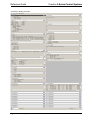
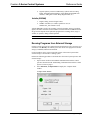
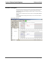
1.
Use the Address Book in Crestron Toolbox to create an entry using the
expected communication protocol (USB). When multiple USB devices are
connected, identify the control system by entering the device name in the
Model text box, the unit’s serial number in the Serial text box or the unit’s
host name in the Host Name text box. The host name can be found in the
“System Info” window in the section marked Ethernet; however,
communications must be established in order to see this information in the
“System Info” window.
2.
icon);
Display the control systems’s “System Info” window (click the
communications are confirmed when the device information is displayed.
3-Series Control Systems • 7
Reference Guide
Crestron 3-Series Control Systems
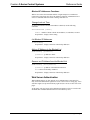
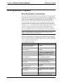
“System Info” Window for the MC3
8 • 3-Series Control Systems
Reference Guide – DOC. 7150A
Crestron 3-Series Control Systems
Reference Guide
Once the system information is displayed a variety of functions are available to the
user. For more information, refer to the Crestron Toolbox help file.
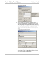
TCP/IP Connection
NOTE: DHCP is enabled by default in 3-Series Control Systems. Crestron Toolbox
autodiscover can be used if the control system has access to the DHCP server.
Before communicating with an Ethernet-enabled control system over TCP/IP, a static
IP address or the address/host name of the DHCP server (if DHCP is to be used)
must be obtained from the network administrator. The USB connection previously
described must be used to configure the unit’s TCP/IP settings. After configuring the
IP information of the control system, further communications can be done over
TCP/IP. For more information, refer to the Crestron e-Control Reference Guide
(Doc. 6052) at www.crestron.com/manuals.
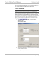
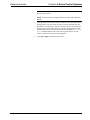
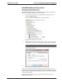
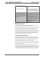
1.
Select Functions | Ethernet Addressing… to open the “Ethernet
Addressing” window.
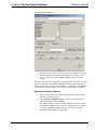
“Ethernet Addressing” Window
2.
Enable TCP/IP communications by checking Enable Ethernet and configure
for static or dynamic IP operation.
a)
Configure for static IP Operation
i.
Reference Guide – DOC. 7150A
Clear (de-select) the Enable DHCP check box.
3-Series Control Systems • 9
Crestron 3-Series Control Systems
Reference Guide
ii.
iii.
iv.
Enter the static IP address and address mask in the address
fields. If applicable, enter the default gateway address. If data
is not to be routed outside the LAN, the default gateway can
be left blank.
Enter the host name in the Host Name field. The host name
identifies the control system on the network and is
automatically translated into the numerical IP address. The
host name can consist of up to 64 characters. Valid characters
are 0–9, A–Z (must be uppercase), and the hyphen. No other
characters are valid. The host name cannot begin with a dash
or number. If a host name is specified, this host name can be
entered instead of the IP address in the Address Book.
The Domain Name is an additional qualifier that some
networks may need to resolve the name properly.
b) Configure for dynamic IP Operation (DHCP)
i.
Select the Enable DHCP check box to enable the processor to
be assigned a dynamic IP address from the DHCP server.
ii.
Select both the Enable DHCP and Enable WINS check boxes
for Windows NT 4.0 Server. The address of the WINS server
is provided by the DHCP server.
iii.
Enter the fully-qualified domain name (FQDN) of the control
system into the Host Name field. The host name identifies the
control system on the network and is automatically translated
into the numerical IP address. The host name can consist of up
to 64 characters. Valid characters are 0–9, A–Z (must be
uppercase), and the hyphen. No other characters are valid. The
host name cannot begin with a dash or number.
iv.
If applicable, enter the domain into the Domain Name field.
This is only necessary if DHCP is being configured on an
Ethernet connection to a control system that currently has a
static address. The domain name is used to reconnect to the
control system after it reboots. With a serial connection, the
domain name does not need to be entered.
The domain name supplied by the DHCP server overwrites the
domain name that is indicated in this field.
v.
To request a new IP address from the DHCP server click the
Renew DHCP button.
NOTE: Other settings can be configured as well. Refer to the
Crestron Toolbox help file for more information.
3.
Click OK to reboot the control system and set the new IP information.
Once the IP settings have been assigned, the control system can
communicate using the USB connection or a TCP/IP connection.
For TCP/IP, use CAT5 straight through cables with 8-pin RJ-45 connectors
to connect the LAN port on the control system and the LAN port on the PC
to the Ethernet hub. Alternatively, a CAT5 crossover cable can be used to
connect the two LAN ports directly, without using a hub. The following
figure illustrates pinouts for straight through and crossover RJ-45 cables.
Pins 4, 5, 7, and 8 are not used.
10 • 3-Series Control Systems
Reference Guide – DOC. 7150A
Crestron 3-Series Control Systems
Reference Guide
RJ-45 Pinouts
4.
Open the address book in Crestron Toolbox by selecting Tools | Manage
Address Book or clicking
.
5.
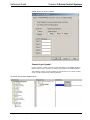
Create a new entry for the control system by clicking Add Entry or
pressing F3.
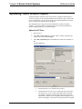
6.
Enter a name for the control system connection and select TCP as the
connection type.
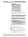
“Address Book” Window - Entering New TCP-IP Entry
Reference Guide – DOC. 7150A
7.
Enter the IP address or host name of the control system that was created on
page 10.
8.
Click OK to save the address book entry.
9.
To verify the connection, click the
“System Info” window is displayed.
icon. If the settings are correct, the
3-Series Control Systems • 11
Crestron 3-Series Control Systems
Reference Guide
Troubleshooting Communications
Use the following checklist if communication cannot be established with the control
system.
•
Verify that the correct cables are being used. With a TCP/IP connection, a
CAT5 cable with 8-pin RJ-45 connectors and the wiring shown on page 11
must be used.
•
Using a USB cable, connect the control system to a PC. Using Crestron
Toolbox go to Tools | Manage Address Book. Select the appropriate entry
for the control system and verify the correct settings have been made. Click
OK. In Toolbox navigate to Tools | System Info. When the “System Info”
window opens, select the communication method from the drop-down
menu. Communication is confirmed when the system information is loaded
on the screen.
If after performing all of the troubleshooting steps described in this section,
communication can still not be established or the control system is still locked up,
reload the device’s firmware.
Refer to the procedure below to erase existing and install new 3-Series Control
System firmware:
NOTE: This procedure erases the control system’s firmware and reinstalls it. If
problems persist before a SIMPL Windows program is loaded, contact Crestron’s
True Blue Technical Support Group. If the system locks up after a SIMPL Windows
program is loaded, there is probably an issue with the SIMPL Windows program.
1.
Download the Package Update File (.puf); save it in any directory.
2.
There are two ways to use this .puf file:
NOTE: A USB connection is the recommended type due to ease of use.
•
Double-click the filename. This starts the Package Update Tool as a
standalone application. When the Crestron Toolbox address book
opens, choose an existing connection type (i.e., USB, TCP, or Serial) or
add a new entry for a connection from the PC to the control system.
Click OK.
-or-
•
12 • 3-Series Control Systems
In Toolbox, click Tools | Package Update Tool. The operator is asked
to specify the .puf file. Click Select… to choose the .puf file. Click the
address book icon to open the address book and select an existing
connection type (i.e., USB, TCP, or Serial) or add a new entry for a
connection from the PC to the control system.
3.
The Package Update Tool connects to the control system. It analyzes the
software versions on the control system and compares them to the versions
in the .puf. It recommends which firmware files should be updated. The
user may choose to manually override the suggestions. This is only
recommended for advanced users.
4.
When the desired files to be updated have been selected, click Update. The
Package Update Tool upgrades the selected firmware. A status message is
displayed when the firmware upgrade is complete.
Reference Guide – DOC. 7150A
Crestron 3-Series Control Systems
Reference Guide
3-Series Console Commands
Introduction
The 3-Series processor is capable of understanding and responding to a set of
recognizable words known as console commands. The commands are sent through
the Text Console in Crestron Toolbox. The processor, in essence, is a computer
capable of interpreting commands received by the console via the following
methods:
•
USB communication with a PC via the USB port on the control system
•
Ethernet communication via CTP (Crestron Terminal Protocol—
reserved port number, default port is 41795)*
•
Ethernet communication via Secure CTP over a SSL connection to port
41797 at the IP address of the processor*
•
Telnet (default port is 23)*
•
Cresnet for processors operating in the Cresnet slave mode (refer to
“Master-Slave Mode” on page 30)
Another method for submitting a command to the console is to use the “Console” or
“User Program Commands” symbols in SIMPL Windows in the control system
program. The “Console” symbol transmits and receives serial data to and from the
control system’s console. The “User Program Commands” symbol allows data typed
at the console to be sent to the program.
NOTE: The method of transmitting each command to the control system varies
from command to command.
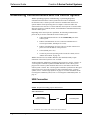
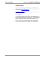
SIMPL Windows Symbols
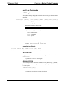
Enable Special Symbols
The “Console” and “User Program Commands” symbols only appear in the System
Control folder in the Symbol Library after enabling a special symbol set for display.
To enable this set while in SIMPL Windows, select Options | Preferences, which
opens the “SIMPL Windows Preferences” window. In the Program Editing tab and
under the Symbol Set area, select Special as shown in the following diagram. Click
OK.
*
Reference Guide – DOC. 7150A
These methods are only available if the control system supports Ethernet.
3-Series Control Systems • 13
Crestron 3-Series Control Systems
Reference Guide
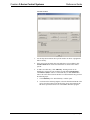
“SIMPL Windows Preferences” Window
Console Logic Symbol
Use the “Console” symbol to activate console commands via the SIMPL Windows
program. This feature is available for advanced programmers of SIMPL Windows.
After enabling viewing of special symbols as described above, the Console symbol
can be viewed as shown in the following diagram.
The Console Logic Symbol in SIMPL Windows
14 • 3-Series Control Systems
Reference Guide – DOC. 7150A
Crestron 3-Series Control Systems
Reference Guide
When the program sends data on the TX$ signal of the “Console” symbol, the
control system interprets the console command just as if it were received via the
USB or Ethernet console and outputs a serial string to the RX$ signal of the console
symbol which can be programatically interpreted.
User Program Commands Symbol
Use the “User Program Commands” symbol to send data typed at the console to the
program. This feature is available for advanced programmers of SIMPL Windows.
After enabling viewing of special symbols, the “User Program Commands” symbol
can be viewed as shown in the following diagram.
The User Program Commands Symbol in SIMPL Windows
The “User Program Commands” symbol receives data entered at the 3-Seriess
console prompt using the USERPROGCMD command. The syntax of the console
command requires double quotes before and after the command string. The string
may include escape codes such as "\x".
The double quotes are stripped off and any escape codes are processed before
passing the string to the “User Program Commands” symbol. For example, if the
user types >USERPROGCMD "TURN ON DEBUG", the string TURN ON DEBUG
(without the double quotes) is passed to the “User Program Commands” symbol. The
string can then be processed as desired.
Reference Guide – DOC. 7150A
3-Series Control Systems • 15
Crestron 3-Series Control Systems
Reference Guide
Command Groups
Console commands are grouped logically. Entering help from the console responds
with the following list of categories:
•
All – all 3-Series console commands
•
Device – pertains to the unit itself
•
Ethernet – governs parameters that involve the Ethernet port(s)
•
File – influences the internal file system
•
System – sets system-wide parameters
•
RF – displays a list of commands for the radio chip (if available)
•
OSD – displays a list of commands for the on-screen-display (if available)
•
xxx* – displays a list of commands that start with the letters that substitute
xxx
It is possible to find the same command in more than one category. Commands are
case insensitive and can be entered from the appropriate prompt. Help on individual
commands is available by typing the command followed by a ? (e.g.,
ADDMASTER ?).
*
16 • 3-Series Control Systems
Add “:InstanceNum” after the command to redirect to particular instance.
Reference Guide – DOC. 7150A
Crestron 3-Series Control Systems
Reference Guide
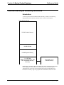
3-Series Memory & Directory Structure
Introduction
A 3-Series processor has 256 MB of built-in memory (volatile). The following
diagram illustrates the memory structure of the 3-Series Control System.
3-Series Memory Structure
256 MB Volatile Memory
128 kB NVRAM
128 MB System Memory
1 – 8 GB Flash
(SIMPL Program Storage, Web
Files, Accessible Directory
Structure)
Expandable Using
External Memory
Flash memory contains the file system inside the 3-Series control engine. NVRAM
contains program variables that are retained after the loss of electrical power.
Volatile memory is lost after a power failure. Refer to the lists that follow for a
breakdown of memory usage for program-related information stored in the unit.
Reference Guide – DOC. 7150A
3-Series Control Systems • 17
Crestron 3-Series Control Systems
Reference Guide
Flash
•
SIMPL Program
•
SIMPL+ Modules
•
Operating System (.cuz file)
The files that reside in flash conform to a flat directory structure. The following table
presents the structure of the overall file system.
The directory structure of the 3-Series Control System can be broken down into two
parts. The first part resides on the on-board flash memory and the second resides on
the optional external memory. Programs, data files, and data can be stored in the onboard flash or the optional external memory. This section briefly describes the
structure of the file system.
The files that reside in the internal flash conform to a flat directory structure while
the external memory system contains a fully FAT32 compatible file system to allow
the same external memory to be used in a Windows environment. The table that
follows presents the structure of the overall file system.
Control System Directory Structure
TOP LEVEL SECONDARY LEVEL
\
DESCRIPTION
Root of the file system
SYS
Contains various system configuration
files
HTML
Web pages
SIMPL\APPXX
Control system program files (where XX
is the program number)
USER
Used for user-defined files
RM, RM2
The mounting point for the external
removable media
NVRAM
NVRAM Legacy Directory
ROMDISK\User\Display
Contains the files for the users on screen
display
Although the file system names are case insensitive, the case is preserved to maintain
file checksums. The compact flash directory only appears when a compact flash card
is inserted into the system. To reference files on the external memory, prefix the
“\RM\” to any fully qualified path from the Windows environment. For example, if
the file in Windows is “\MyDirectory\MySubdirectory\MyFile.ext”, the complete
3-Series path for a file on the first compact flash slot (onboard) is
“\RM\MyDirectory\MySubdirectory\MyFile.ext”.
When the SIMPL Windows program is stored on the external memory, the files
reside in the directories \RM\SIMPL\APPXX where XX is the program number.
When web pages are stored on the external memory, the directory is \CF0\HTML.
Storing the program or web pages on the removable media gives those files
precedence over files stored on internal flash. That is to say, if different programs are
stored in both internal flash and external memory, the program on external memory
runs at boot-up.
Non-volatile (NVRAM)
1.
18 • 3-Series Control Systems
SIMPL+ Variables (Default if no options are specified, or using
"nonvolatile" qualifier or #DEFAULT_NONVOLATILE)
Reference Guide – DOC. 7150A
Crestron 3-Series Control Systems
2.
Reference Guide
Signals explicitly written to NVRAM (by symbols such as Analog
RAM, Analog RAM from database, Serial RAM, Serial RAM from
database, Analog Non-volatile Ramp, Digital RAM, etc.)
Volatile (SDRAM)
1.
Digital, analog, and serial signal values
2.
SIMPL+ Variables (if "volatile" qualifier is used, or
#DEFAULT_VOLATILE is used)
Volatile SDRAM is used by the operating system for dynamic storage of variables,
signals, and other constructs used at runtime. The actual amount of SDRAM used at
any given time depends on the particular program that is running; that is, usage is
variable, or dynamic, during normal operation.
NOTE: SDRAM is internal to operations and is not available to the programmer.
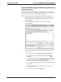
Running Programs from External Storage
Certain 3-Series processors are equipped with external storage ports. On power-up or
a hardware reset (HW-R), the control system first checks for a program on external
storage (if installed) and then internal flash.
Crestron Toolbox can be used to control the actions of the control system when
external storage is inserted into a running system.
Perform the following procedure to determine how the control system operates with
external storage:
1.
Open Crestron Toolbox and establish communications with the control
system as described in the “Establishing Communications with the Control
System” section on page 6.
2.
Select Functions | Compact Flash to display the “Compact Flash”
window.
“Compact Flash” Window
Reference Guide – DOC. 7150A
3-Series Control Systems • 19
Crestron 3-Series Control Systems
Reference Guide
NOTE: Auto-Run mode is only available when external memory is inserted
into the control system.
NOTE: Control systems are shipped with the Auto-Run mode enabled by
default.
20 • 3-Series Control Systems
3.
Click the Enable Auto-Run check box to enable the Auto-Run mode. When
operating in the Auto-Run mode, the control system is automatically reset
and runs the external program when the external storage is inserted into the
control system. If the external storage is removed, the program in internal
Flash automatically runs. When Auto-Run mode is disabled, the Program
Reset command must be sent to the control system after the external
storage is inserted or removed to run the program.
4.
Click OK or Apply for changes to take effect.
Reference Guide – DOC. 7150A
Crestron 3-Series Control Systems
Reference Guide
3-Series Control System Error Messages
Introduction
This section provides a brief description of 3-Series error messages that may be
encountered. Error messages may be the result of hardware or software failure,
hardware incompatibility with software definitions, or a programming error.
Error messages created by the control system are written to an error log that is stored
in the control system’s RAM. The error log can be saved on removable media on
processors that support it. Use Crestron Toolbox to display the error log.
NOTE: To save the error log in non-volatile memory, use the PERSISTENTLOG
console command to have the error log write to the removable media. For more
information, refer to “Running Programs from External Storage” on page 19
Error Levels
The following table lists and defines the four levels of error messages that may appear.
Error Message Levels
TYPE
DEFINITION
Notice
An event has occurred that is noteworthy, but does not affect program
operation.
Warning
An event has occurred that could affect program operation, but the
program can still run normally.
Error
An event has occurred that indicates that the program is not operating
as expected.
Fatal
An event has occurred that prevents the program from running.
Error Format
Each error message has the following format: Level: Message
Some messages have a suffix with additional information in parenthesis:
{Error Level} :{Application}[App#] # [Date/Time] # Message
Only the first two items (level and message) within the error format are of any
immediate value to the programmer.
•
Level – defined in the preceding table
•
Message – varied
•
Error# – unique identifier for Crestron use
•
Extended Error# – unique identifier for Crestron use
•
Reserved# – not yet defined; for future use
NOTE: It is important to report the exact error message to a Crestron customer
service representative. Also, be as specific as possible regarding the events that lead
to the error (e.g., pressing a certain sequence of buttons, etc). Finally, provide the
compiled archive file.
Reference Guide – DOC. 7150A
3-Series Control Systems • 21
Crestron 3-Series Control Systems
Reference Guide
Viewing Error Messages with Error Log Function in
Crestron Toolbox
Crestron Toolbox can be used with any 3-Series Control System to view messages
stored in the error log. For more detailed error messages refer to “Viewing Error
Messages with Text Console in Crestron Toolbox” on page 23.
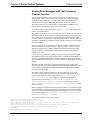
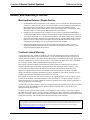
Use the following procedure to manage the Error Log with Crestron Toolbox:
1.
Open Crestron Toolbox and establish communications with the control
system as described in “Establishing Communications with the Control
System” on page 6.
2.
Select Functions | Error Log to open the “Error Log” window.
“Error Log” Window
3.
22 • 3-Series Control Systems
The “Error Log” window opens with the latest error messages from the
control system.
•
To refresh the error log, click Retrieve Error Log from Device.
•
Top copy the error log to the computers clipboard, click Copy to
Clipboard.
•
To clear the error log, click Clear Error Log in Device and click Yes
when prompted to confirm. The MSG / ERR LED on the front panel
(if present) is extinguished. The current log is displayed.
•
To save the error log, click Save As…, select a filename and directory,
and click OK.
•
To retrieve a saved error log, select Open…, select the file to be
opened, and click OK.
•
To close the window, click the Close button.
Reference Guide – DOC. 7150A
Crestron 3-Series Control Systems
Reference Guide
Viewing Error Messages with Text Console in
Crestron Toolbox
The persistent log (PLOG) is a log of error messages that are identified by the
control system. The latest PLOG can be viewed in the Text Console in Crestron
Toollbox and are available after a control system reboot. The control system, or
attached device, may have a MSG LED that indicates an error has occurred.
The control system stores current log files at “\SYS\PLOG\CurrentBoot”. The
current log file is locked and cannot be opened for transfer.
To view the contents of the current PLOG enter ERR PLOGCURRENT into the text
console in Crestron Toolbox.
The control system checks for new error messages every 2 minutes and commits any
messages to a log file for viewing. The control system creates up to 9 temporary log
files (“Crestron_01.log” to “Crestron_09.log”) and one permanent initial log file
(“Crestron_00.log”). Log files have a 256 kB maximum size for each file—when the
size limit is reached the next log file is created. Log files continue to be created until
all 10 files are full.
After all 10 log files are created and the 10th log file reached its 256 kB maximum
size the control system overwrites the first temporary log file (“Crestron_01.log”)
and begins logging until it is full. The control system then overwrites the second
temporary log file (“Crestron_02.log”). This operation repeats as long as there
continue to be errors.
If a soft reboot is performed any pending messages are written to the latest log file
and zipped into one file. On reboot the zipped file at “\SYS\PLOG\CurrentBoot” is
moved to “\SYS\PLOG\PreviousBoot”. During subsequent reboots the zipped file
from “\SYS\PLOG\PreviousBoot” is moved to “\SYS\PLOG\ZippedLogs” for future
storage.
The amount of space reserved for current and zipped log files is 50 MB. If the
control system runs out of space for log files it deletes the oldest log file. The control
system also has a maximum of 50 log files and deletes the oldest log file once the
maximum has been reached.
The control system continues logging errors as long as there are not over 250
messages per 2 minute period for two consecutive 2 minute logging periods. For
each error period the text console results displays PersistentLog: Error
state threshold met if error logging is suspended. When logging is
suspended the log file displays PersistentLog: Consecutive error
states detected; logging is suspended. The user also receives a
PersistentLog is suspended, please contact dealer. message
in the text console.
Message logging is resumed when there has been less than 10 error messages logged
for 10 consecutive 2 minute logging periods. When logging is resumed all messages
from the 10 consecutive 2 minute logging periods are logged to the log file. The log
in text console displays PersistentLog: Consecutive quite states
detected; logging is resumed.
An example of a PLOG result is shown below:
Persistent log contents during current boot:
Notice: nk.exe # 09:38:26 10-09-2013 # Power On
Notice: nk.exe # 09:38:26 10-09-2013 # System startup: MC3 [v1.007.0019 (May 15 2013) #00A09982]
setIP: Registry static IP setting = 0.0.0.0
Info: nk.exe # 09:38:26 10-09-2013 # UpdateDHCPOptions:HostName option selected
Info: nk.exe # 09:38:26 10-09-2013 # Updating DHCP options on boot
USB RESET
DRIVER_VERSION : 201, DATECODE : 111708
Reference Guide – DOC. 7150A
3-Series Control Systems • 23
Crestron 3-Series Control Systems
Reference Guide
Lan9221 identified. ID_REV = 0x92210000
USB RESET
Use IntPhy
Auto-MDIX Enable by default!!!
LayMgr.cpp: Layout Manager successfully initialized to 1
Info: CrestronMonitor.exe # 09:38:31 10-09-2013 # Crestron applications already installed
Warning: ConsoleServiceCE.exe # 09:38:36 10-09-2013 # ReadInInitialLinkStatus - Attempt to read
static DNS failed ... Defaulting
Notice: ConsoleServiceCE.exe # 09:38:37 10-09-2013 # Got Security Flag: 0
Info: TLDM.exe # 09:38:45 10-09-2013 # THAL loading now ..
Info: TLDM.exe # 09:38:45 10-09-2013 # TLDM Starting..
Info: TLDM.exe # 09:38:45 10-09-2013 # Resuming rcv task now
Info: TLDM.exe # 09:38:45 10-09-2013 # Successfully registered with the console service - Console
available
Info: RfGateway.exe # 09:38:46 10-09-2013 # TLDMInterfaceReadInMessageQueueSize - Queue size
defaults to 500
Info: nk.exe # 09:38:46 10-09-2013 # IEX: Host chip found (count 2)
Info: nk.exe # 09:38:46 10-09-2013 # IEX: NCP initialized successfully!
Info: nk.exe # 09:38:46 10-09-2013 # IEX: halStackSeedRandom=348A9A45
Ok: SimplSharpPro.exe # 09:38:58 10-09-2013 # Successfully registered the application with the TLDM
Ok: SimplSharpPro.exe # 09:39:03 10-09-2013 # Creating 5 User threads with initial priority 253
Info: CRESLOG.exe # 09:39:04 10-09-2013 # PersistentLog: Logging is started!
Notice: ConsoleServiceCE.exe # 09:41:13 10-09-2013 # USB Connection has been made.
USB RESET
USB RESET
Persistent log contents during current boot end
Reading Error Messages
Error messages are dispayed in the following format:
{Error Level} :{Application} [App#] # [HH:MM:SS MM-DD-YYYY] # Message
The error level field indicates the severity of the error message. Error levels range
from OK to Fatal:
•
OK
•
Notice
•
Warning
•
Error
•
Fatal
The application field indicates the running program that produced the error:
24 • 3-Series Control Systems
•
ConsoleServiceCE.exe – This is the application that runs all the
console transports, such as Ethernet and USB. It implements some basic
commands such as reboot.
•
SystemCommandProcessor.exe – This is the application that handles
all system level commands, such as restore.
•
CresLog.exe – This is the application responsible for writing error
messages, RM Logging, and Persistent Log.
•
RfGateway.exe – This is the application that runs on control systems
with built-in RF gateways.
•
RouterTransportProcess.exe – This is the application responsible
for the router communication subsystem. Applicable only to control
systems with a Control Subnet port.
•
DisplayManager.exe – This application is responsible for user
interface projects such as front panel, on-screen display, or touch screen.
Reference Guide – DOC. 7150A
Crestron 3-Series Control Systems
Reference Guide
•
SSHD.exe – This application handles all SSH and SFTP traffic.
•
TLDM.exe – This application is the Top Level Device Manager,
responsible for all data movement across the different sub-systems.
•
CIPCommandProcesor.exe – This is the Ethernet Stack application
responsible for all CIP communications and SIMPL+ Logic symbols for
Ethernet.
•
BACnet.exe – This application is the BACnet stack which handles the
3-Series BACnet implementation.
•
CloudClient.exe – This is the application responsible for the Crestron
Cloud projects.
•
SimplSharpPro.exe – This is the application that runs the SIMPL# Pro
applications
•
LogicEngine.exe – This application runs SIMPL Windows logic
programs.
•
SPlusManagerApp.exe – This handles all SIMPL+ and SIMPL#
modules in a single program.
•
NK.EXE – This application is the underlying kernel for the operating
system.
The APP# is displayed when there are multiple instances of a single application
(e.g., LogicEngine.exe, SPlusManagerApp.exe, and SimplSharpPro.exe) the APP#
indicates the program slot (1–10) which the application is associated.
Reference Guide – DOC. 7150A
3-Series Control Systems • 25
Crestron 3-Series Control Systems
Reference Guide
Passthrough Mode
NOTE: This procedure requires the use of Crestron Toolbox.
Passthrough mode allows a control system to act as a conduit to a device that is
serially connected to the Crestron system. Crestron Toolbox can then serially
communicate with a controlled device separate from the control system program.
This aids in troubleshooting a serial device that is connected to the network by
isolating the device from the system or the program running in the control system
without moving any wiring.
NOTE: Before using Passthrough mode to connect to a serial port on an
Ethernet device, the IP ID and associated IP address of the Ethernet device must
be listed in the control system's IP table.
Passthrough mode cannot be used with Cresnet devices that utilize slots in the
SIMPL Windows programming symbol. For example, the COM port on the
C2N-CAMIDSPT is designated as Slot 2, Port A. Passthrough mode cannot be used
to access this COM port. The COM ports on the ST-COM are not within slots and
can use passthrough for these COM ports. The “System Views” window of SIMPL
Windows shows the programmer if a COM port is a port on a device or a port within
a slot on a device.
Use the following procedure to enter Passthrough mode for connecting to serial
devices:
26 • 3-Series Control Systems
1.
Open Crestron Toolbox and establish a serial connection to the 3-Series
Control System as described in “Establishing Communications with the
Control System” on page 6.
2.
Open the Address Book. If the device has not already been added, add an
address for the control system:
•
Select Indirect for the Connection Type.
•
Select the location for the Device is at field. Refer to the illustration on
the following page for visual guidance.
Reference Guide – DOC. 7150A
Crestron 3-Series Control Systems
Reference Guide
“Address Book” Window
Reference Guide – DOC. 7150A
3.
Click OK.
4.
Add another indirect address for the serial device by clicking Add Entry
(or F3) and type a name for the entry.
a.
Click Indirect.
b.
Under Device is at select COM Port (Passthrough). A dialog box
opens. Refer to the illustration below for visual guidance.
3-Series Control Systems • 27
Crestron 3-Series Control Systems
Reference Guide
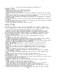
Control Subnet
The AV3, PRO3, and CP3N (referred to as “control system” for the rest of this
section) have a dedicated Control Subnet which allows for dedicated communication
between the control system and Crestron Ethernet devices without interference from
other network traffic on the LAN.
The Control Subnet can host up to 64,000 Crestron Ethernet devices. Connect a
Crestron Ethernet switch such as the CEN-SWPOE-16 16-Port Managed PoE Switch
(sold separately) to the control system’s CONTROL SUBNET port to use as a
connection point for a variety of Crestron Ethernet devices. The CONTROL
SUBNET port is used to communicate with Crestron Ethernet devices on a subnet
that is independent of the local area network connected to the LAN port. When using
the Control Subnet, observe the following:
•
The control system acts as a DHCP server to all devices connected to the
Control Subnet and assign IP addresses as needed.
•
A DNS server is built in to the control system to resolve host names.
•
Only Crestron Ethernet devices should be connected to the Control Subnet.
The control system can operate in Isolation mode. Take the following into account
when operating in Isolation mode:
•
Devices on the Control Subnet do not have access to any resources on the
LAN side. This means that if a touch screen with a smart object that
requires Internet access is installed on the Control Subnet operating in
Isolation mode, the smart object cannot work.
•
Devices on the LAN do not have access to any devices on the Control
Subnet. This includes Crestron Toolbox when it is connected to the LAN.
To configure devices on the Control Subnet with Crestron Toolbox, the PC
running Crestron Toolbox must be physically connected to the Control
Subnet.
•
Any NAT/Portmapping rules that were previously created do not work
when the control system is in Isolation mode.
CAUTION: Do not connect the CONTROL SUBNET port to the LAN. The
CONTROL SUBNET port must only be connected to Crestron Ethernet devices.
NOTE: If the control system is operating in Isolation mode, Crestron Ethernet
devices that require Internet access should not be connected to the CONTROL
SUBNET port (either directly or indirectly). Any Crestron Ethernet device that
requires an Internet connection should be connected to the local area network.
28 • 3-Series Control Systems
Reference Guide – DOC. 7150A
Crestron 3-Series Control Systems
Reference Guide
Control Subnet Application
AV3/PRO3
UT 7
TP 6
LYOU
REA 45
3
G
2
X
MA
81
G
/DC ~2.4A
UT 7 S
AC
0VHz
TP 6 S G
1A30V 100-24
60
OU
LRIA
G
50/
- SE 45 G GS
IR 3
S
2 S GS
G
S
T
NEZ G
5C
S2
OM
24Y
AS
M 4C
CL
8
CO
G7
3
6
75W
M
I/O 5
M 2 CO
34
24V
CO232/485
G
12
RS422
R
RY
M1
RAATIN
MO
FO
CO232/485RS
ME
LNU
RS422
WN
E MA
DO
RS
SE
TS
TNAC
CO
L
RO
ET US B
NT
BN
CO
SU
N
LA
LAN
LA
G
TX
RX
G
TX
RX
G
TX
RX
G
TX
RX
Projector
G
G
TX
T XRX
RXRTS
T X+
CTS
RX+
G
G
TX
T XRX
RXRTS
T X+
CTS
RX+
OM
6
1
S
8
G
N
Control Subnet
Media
Server
CEN-SWPOE-24
24-PORT MANAGED PoE SWITCH
CEN-SWPOE-16
RN
HE
ET
ER
11
R OV RT
WE / POX 10
PO 2 W MA
00 34. W 9
/10 X 255
AL
100 MA
TOT8
10/
1
2
ELEC
G
ET
12
13
14
15
16
A
-240V
100-2.0
4.8
60H
- 50/
z
7
6
5
A
US
4
47
076
3
, NJ
LE.IGH
INC
ICSCK
RO
TRON
Projection
Screen
Crestron Ethernet Devices
Reference Guide – DOC. 7150A
3-Series Control Systems • 29
Crestron 3-Series Control Systems
Reference Guide
Master-Slave Mode
Introduction
Master-Slave mode is a network configuration that allows a Crestron 3-Series
processor to access ports on other Crestron control systems over Ethernet. By
attaching a slave control system to a master control system, the master control
system can use ports it may not normally have (I/O, IR, RF, etc.).
In a master-slave environment, the master control system contains the program that
controls all Cresnet and Ethernet devices attached to it. The slave control system
turns off its processing capabilities and behaves exactly like any other Cresnet or
Ethernet device. It obeys the program in the master control system, making its ports
available for control by the master. By using slave systems, only one master program
has to be written to control multiple slave systems.
NOTE: If there is a need for a control system to run its own program but be able to
communicate with other control systems, use the “Intersystem Communications”
symbol for peer-to-peer communications between control systems over Ethernet or
serial communications. For more information on the Intersystem Communications
symbol, refer to the SIMPL Windows help file.
Depending on a control system’s communications capabilities, a control system may
function as a Cresnet master, an Ethernet master, or an Ethernet slave.
NOTE: A 3-Series Control System cannot be slaved to a 2-Series Control System.
Definitions
Cresnet Master
When in the Cresnet master mode (the default mode for most control systems), a
master control system can control Cresnet and Ethernet devices (if equipped with
Ethernet capabilities) as well as control systems operating in the Cresnet slave mode.
Control systems with Cresnet and Ethernet capabilities can function as a Cresnet
master and Ethernet master simultaneously.
Ethernet Master
When operating as an Ethernet master, a master control system can control Ethernet
and Cresnet devices (if equipped with Cresnet capabilities) as well as control
systems operating in the Ethernet slave mode.
Control systems with Ethernet and Cresnet capabilities can function as an Ethernet
master and a Cresnet master simultaneously.
Ethernet Slave
A control system operating in the Ethernet slave mode operates as an Ethernet device
and makes its built-in ports (except for Ethernet) available to a master control
system. While operating in the Ethernet slave mode, any program that is loaded into
the control system does not run.
When operating in the Ethernet slave mode, the control system can address any
installed hardware, but it cannot address Ethernet network devices. Unlike the
2-Series control systems that cannot use the Cresnet port on a 2-Series slave, the
3-Series master and 3-Series slave each have their own independent Cresnet bus.
This allows the 3-Series master to assign Cresnet IDs 03 to FE and the 3-Series slave
30 • 3-Series Control Systems
Reference Guide – DOC. 7150A
Crestron 3-Series Control Systems
Reference Guide
to issue Cresnet IDs 03 to FE, ultimately doubling the number of devices in the
network.
Slave control systems with Ethernet and Cresnet abilities can only be configured to
operate as an Ethernet slave.
The 3-series can only be an Ethernet slave to another 3-series controller, no Cresnet
slaving is supported. A 2-series can be a Cresnet or Ethernet slave to a 3-series.
Refer to the following table for reference.
NOTE: There can only be a single master IP table entry.
Master / Slave Reference Table
MASTER
SLAVE
2-Series
2-Series
Cresnet /
Ethernet
3-Series
Cresnet /
Ethernet
3-Series
Ethernet
Differences from the 2-Series Control Systems
•
Adding a Master IP Table using the ADDMaster command does not
require a reboot.
•
Removing a Master IP Table entry using the REMMaster command does
not require a reboot.
•
The prompt on the 3-Series Control System never changes.
•
Use the MIPTable command to get the master IP Table entry.
•
There is a new command which indicates the slave status.
•
New commands to configure the slave behavior.
Functional Behavior
A 3-Series Control System can switch back and forth between the slave mode and
normal mode (running registered user programs) without requiring a reboot. There
are certain parameters that determine how long the slave controller tries to connect to
the master before reverting back to the regular mode.
Assuming No Master IP Table Entry When Booting the
System
Reference Guide – DOC. 7150A
•
Adding a Master IP table entry enables the slave to start connecting to the
master. Once the slave is connected all user programs stop executing and
the device enters into the slave mode.
•
Stopping the program on the master does not force the slave back into the
regular mode. The slave tries to connect for the period based on the
configuration parameters before reverting back to the regular mode. Once
this happens, the slave controller does not go back into the slave mode until
the control system reboots or the master IP Table entry is added again. An
error gets logged indicating this condition
3-Series Control Systems • 31
Crestron 3-Series Control Systems
Reference Guide
o
•
Ethernet Slave – Reached max count of connect responses being
rejected by master before a successful connect. Not retrying Initiating normal behavior
Removing the master IP table entry forces the controller to revert back to
the normal mode.
Assuming Master IP Table Entry Exists When Booting the
System
The slave tries to connect to the master for the period set by the configuration
parameters. If the slave can connect successfully, it enters the slave mode. If not the
slave enters into the normal mode and then behaves as described above.
Master / Slave Console Commands
ADDMASTER
This command adds a master entry to the IP table.
ADDMaster [cip_id] [ip_address/name]
cip_id - ID of the CIP node (in hex)
ip_address/name - IP address in dot decimal notation or name of the
site for DNS lookup
REMMASTER
This command removes a master entry from the IP table.
REMMaster [cip_id] [ip_address/name]
cip_id - ID of the CIP node (in hex)
ip_address/name - IP address in dot decimal notation or name of the
site for DNS lookup
MIPTABLE
This command displays the master IP table.
MIPTABLE [-T]
-T displays the data in a table format
No arguments - Shows the IP table for the Master Entry
SLAVESTATUS
This command displays that status of the slave processor.
SLAVESTATUS
No parameter is needed – Displays the slave status
ETHSLVCONNFCNT
This command sets the default Slave connect response reject count. If the command
is entered with no parameter console displays the current connect response reject
count.
ETHSLVCONNFCNT [CONNECTFAILEDCOUNT]
32 • 3-Series Control Systems
Reference Guide – DOC. 7150A
Crestron 3-Series Control Systems
Reference Guide
CONNECTFAILEDCOUNT - Set the default slave connect response reject
count. Stops connecting after this number of connect response rejected
No Parameter - Show current connect response reject count
The ETHSLVCONNFCNT command tells the slave after how many unsuccessful
connect attempts to the master should the slave revert back. The default is 100 and
this happens about every 10 seconds. If the count was set to the slave would reset
back in about a minute.
This takes care of a scenario where that particular IP address is UP and running but
does not have a program which listens to that ID.
ETHSLVCONNTIMEOUT
This command sets the default Slave connection timeout setting. If the command is
entered with no parameter it displays the current connect timeout.
ETHSLVCONNTIMEOUT [TIMEOUTINSEC]
TIMEOUTINSEC - Set the default slave connect timeout in seconds. Indicates
the time (in seconds) in which the normal program resumes
No Parameter - Show current slave connect timeout
The ETHSLVCONNTIMEOUT command tells the slave after how many seconds to
wait after being unable to a make a TCP level connections should the slave revert
back to running a program...
This takes care of the case where the slave tries to connect to a non-existant IP
address or to a unit which is not up and running.
Reference Guide – DOC. 7150A
3-Series Control Systems • 33
Crestron 3-Series Control Systems
Reference Guide
Dynamic Host Configuration Protocol (DHCP)
Introduction
Crestron’s 3-Series Control Systems support DHCP (Dynamic Host Configuration
Protocol) in a Windows Server environment.
When using DHCP, a dynamic IP address is automatically assigned to a device on
the network. These IP addresses are called “dynamic” because they are only
temporarily assigned, or leased, to the device. After a certain period of time the
DHCP lease expires and may change. When a device connects to the network (or the
Internet) and its dynamic IP address has expired, the DHCP server assigns it a new
dynamic IP address.
The purpose of DHCP is to let network administrators centrally manage and
automate the assignment of IP addresses in an organization’s network. DHCP greatly
reduces the work necessary to administer a large IP network. Without DHCP, the
administrator has to manually configure the IP address each time a computer is
added to the network or moves to a different location.
DHCP provides integration with a DNS (Domain Name System) service. This
system allows hosts to have both domain name addresses (such as ftp.crestron.com)
and IP addresses (such as 65.206.113.4). The domain name address is easier for
people to remember and is automatically translated into the numerical IP address.
The domain name address (also called the Fully-Qualified Domain Name, or FQDN)
identifies the owner of that address in a hierarchical format: server.organization.type.
For example, ftp.crestron.com identifies the FTP server at Crestron, with “.com”
signifying a commercial organization.
A DNS server, also called a name server, maintains a database containing the host
computers and their corresponding IP addresses. Presented with the domain name
address ftp.crestron.com, for example, the DNS server would return the IP address
65.206.113.4.
Another name-resolution service is WINS (Windows Internet Naming Service).
WINS is used in conjunction with DNS and DHCP in a Windows NT 4.0 Server
environment.
Windows DHCP/DNS Server Configuration
Crestron’s 3-Series Control Systems support DHCP in all Windows Server
environments
In the following configuration requirements, a scope defines the range of IP
addresses for the network. Typically a scope defines a single physical subnet on the
network. Scopes provide the primary way for the DHCP server to manage
distribution and assignment of IP addresses and any related configuration parameters
to clients on the network.
Scope options are client configuration parameters applied specifically to all clients
that obtain a lease within a particular scope. Some commonly used options include
IP addresses for default gateways (routers), WINS servers, and DNS servers.
34 • 3-Series Control Systems
Reference Guide – DOC. 7150A
Crestron 3-Series Control Systems
Reference Guide
Control System Configuration
1.
Open Crestron Toolbox and establish communications with the control
system as described in “Establishing Communications with the Control
System” on page 6.
2.
Select Functions | Ethernet Addressing… to open the “Ethernet
Addressing” window.
“Ethernet Addressing” Window
3.
Select the Enable DHCP check box to enable DHCP. Select the Enable
DHCP and the Enable WINS (if available) check boxes. (The IP Address
and IP Mask fields are ignored if either check box is selected.)
4.
Enter the host name of the control system in the Host Name field. The host
name identifies the control system on the network and is automatically
translated into the numerical IP address. The host name can consist of up to
64 characters. Valid characters are 0–9, A–Z (all capitals), and the hyphen.
No other characters are valid. The host name cannot begin with a dash or
number.
5.
If applicable, enter the domain in the Domain Name field. This is only
necessary if DHCP is being configured on an Ethernet connection to a
control system that currently has a static address. The domain name is used
to reconnect to the control system after it reboots. With a serial connection,
the domain does not need to be entered.
NOTE: The domain supplied by the DHCP server overwrites the domain
that is indicated in this field.
Reference Guide – DOC. 7150A
3-Series Control Systems • 35
Crestron 3-Series Control Systems
Reference Guide
6.
Once all settings are made, click OK to store the settings and reboot the
control system.
Other Settings
It is possible to change the CIP and CTP port numbers in rare cases where a network
conflict may exist with ports 41794 and 41795.
The web port can be changed for security reasons if no firewall or router is
protecting the network. To prevent attacks by hackers the port can be moved to
another value. Users on the LAN would then have to specify the port number in the
URL (e.g., http//www.crestron.com:49153) where the value after the colon indicates
the web port.
In most cases, the port numbers do not need to be changed.
Once the IP information for the control system has been set, it becomes possible to
communicate with the control system via TCP/IP.
36 • 3-Series Control Systems
Reference Guide – DOC. 7150A
Crestron 3-Series Control Systems
Reference Guide
Secure Sockets Layer (SSL)
Introduction
Ethernet-enabled control systems provide built-in support for Secure Sockets Layer
(SSL), the standard for protecting web-based communication between clients and
servers. SSL is a protocol that provides a secure channel for communication between
two machines. The secure channel is transparent, which means that it passes the data
through, unchanged. The data is encrypted between the client and the server, but the
data that one end writes is exactly what the other end reads. The SSL protocol uses
TCP as the medium of transport.
SSL ensures that the connection between a web browser and web server is secure by
providing authentication and encryption. Authentication confirms that servers, and
sometimes clients, are who they say they are. Encryption creates a secure “tunnel”
between the two, which prevents unauthorized access to the system.
The secure tunnel that SSL creates is an encrypted connection that ensures that all
information sent between the client and server remains private. SSL also provides a
mechanism for detecting if someone has altered the data in transit. If at any point
SSL detects that a connection is not secure, it terminates the connection and the
client and server have to establish a new, secure connection.
SSL uses both public-key and symmetric-key encryption techniques. Public keys are
a component of public-key cryptographic systems. The sender of a message uses a
public key to encrypt data; the recipient of the message can only decrypt the data
with the corresponding private key. Public keys are known to everybody, while
private keys are secret and only known to the recipient of the message. Since only
the server has access to its private key, only the server can decrypt the information.
This is how the information remains confidential and tamper-proof while in transit
across the network.
An SSL transaction consists of two distinct parts: the key exchange and the bulk data
transfer. The SSL Handshake Protocol handles key exchange and the SSL Record
Protocol handles the bulk data transfer.
The key exchange (SSL handshake protocol) begins with an exchange of messages
called the SSL handshake. During the handshake, the server authenticates itself to
the client using public-key encryption techniques. Then the client and the server
create a set of symmetric keys that they use during that session to encrypt and
decrypt data and to detect if someone has tampered with the data. Symmetric key
encryption is much faster than public-key encryption, while public-key encryption
provides strong authentication techniques.
Once the key exchange is complete, the client and the server use this session key to
encrypt all communication between them. They do this encryption with a cipher, or
symmetric key encryption algorithm, such as RC4 or DES. This is the function of the
SSL Record Protocol. There are two types of ciphers, symmetric and asymmetric.
Symmetric ciphers require the same key for encryption and decryption, whereas with
asymmetric ciphers, data can be encrypted using a public key, but decrypted using a
private key.
SSL supports a variety of ciphers that it uses for authentication, transmission of
certificates, and establishing session keys. SSL-enabled devices can be configured to
support different sets of ciphers, called cipher suites.
Reference Guide – DOC. 7150A
3-Series Control Systems • 37
Crestron 3-Series Control Systems
Reference Guide
The encryption algorithms and the key lengths supported in the 3-Series processor
are as follows:
Supported Encryption Algorithms and Key Lengths for 3-Series Processors
NAME
TYPE
SESSION KEY
LENGTHS (BITS)
IN/OUT
DES
Symmetric
40 or 56
DES
3DES
Symmetric
168
3DES
RC2
Symmetric
40
RC2
RC4
Symmetric
40 or 128
RC4
AES
Symmetric
128 or 256
AES
RSA
Asymmetric
1024
RSA
SSL-enabled clients and servers confirm each other’s identities using digital
certificates. Digital certificates are issued by trusted third-party enterprises called
Certificate Authorities (CA). From the certificate, the sender can verify the
recipient's claimed identity and recover their public key. By validating digital
certificates, both parties can ensure that an imposter has not intercepted a
transmission and provided a false public key for which they have the correct private
key.
A CA-signed certificate provides several important capabilities for a web server:
•
Browsers automatically recognize the certificate and allow a secure
connection to be made, without prompting the user. (If a browser
encounters a certificate whose authorizing CA is not in its list of trusted
CAs, the browser prompts the user to accept or decline the connection.)
•
When a CA issues a signed certificate, they are guaranteeing the identity of
the organization that is providing the web pages to the browser.
Alternatively, self-signed certificates can be generated for secure web servers, but
self-signed certificates do not provide the same functionality as CA-signed
certificates. Browsers do not automatically recognize a self-signed certificate; and a
self-signed certificate does not provide any guarantee concerning the identity of the
organization that is providing the server.
There are various Certificate Authorities, notable among them being Thawte and
Verisign. For a fee, a CA investigates the organization hosting the server and issues a
certificate vouching for the identity of the server. The procedure for
obtaining/enrolling for a CA-signed certificate varies with each CA and is described
on their websites (i.e., www.thawte.com or www.verisign.com). However, all CAs
require a Certificate Signing Request (CSR). The CSR can be copied and pasted to
the online enrollment form or sent via e-mail to the CA, along with any other
pertinent information the CA requires. The CA then issues the certificate, usually via
e-mail. The Crestron Toolbox provides all the certificate management tools
necessary to generate a CSR and upload the certificate to the 3-Series processor.
The CA-signed certificate is an ASCII “base64” encoded text (*.cer) file, which the
3-Series processor converts to a binary file called \\SYS\srv_cert.der. As a part of the
CSRprocess, a private key is also created as \\SYS\srv_key.der. It is extremely
important to back up the private key, as it is unique to each CSR. If the private key is
lost the certificate is useless and it would be necessary to begin the enrollment
process all over again.
Here is a description of an SSL transaction:
1.
38 • 3-Series Control Systems
The browser sends a request for an SSL session to the web server.
Reference Guide – DOC. 7150A
Crestron 3-Series Control Systems
Reference Guide
2.
The web server sends the browser its digital certificate. The certificate
contains information about the server, including the server’s public key.
3.
The browser verifies that the certificate is valid and that a trusted CA issued
it.
4.
The browser generates a “master secret” that is encrypted using the server’s
public key and sent to the web server.
5.
The web server decrypts the master secret using the server’s private key.
6.
Now that both the browser and the web server have the same master secret,
they use this master secret to create keys for the encryption and MAC
(message authentication code) algorithms used in the bulk-data process of
SSL. Since both participants used the same master key, they now have the
same encryption and MAC keys.
7.
The browser and web server use the SSL encryption and authentication
algorithms to create an encrypted tunnel. Through this encrypted tunnel,
they can pass data securely through the network.
Though the authentication and encryption process may seem involved, the user
generally does not even know it is taking place. However, the user can tell when the
secure tunnel has been established since most SSL-enabled web browsers display a
small closed lock at the bottom (or top) of their screen when the connection is
secure. Users can also identify secure websites by looking at the website address; a
secure website’s address begins with https:// rather than the usual http://. The web
server listens for a secure connection on the well-known port 443.
SSL Configuration
This section describes the steps required to enable a 3-Series web server for SSL and
obtaining a digital certificate from a Certificate Authority. The steps are summarized
as follows (each step is described in detail later):
•
Establish a serial connection to the 3-Series Control System.
•
Enable SSL using a self-signed certificate.
•
Create an encryption public/private key pair and a certificate-signing
request (CSRbased) on the public key.
•
Back up the private key.
•
Send the CSR to a Certificate Authority such as Thawte or Verisign, who
verify the identity of the requestor and issue a signed certificate.
•
Install the CA-signed certificate and optionally, the root certificate, to the
3-Series Control System.
•
Enable SSL using the CA-signed certificate.
3-Series Control System Requirements
Reference Guide – DOC. 7150A
•
.puf: 1.5.15 or later
•
Crestron Toolbox: 1.23 or later
•
SIMPL Windows: 3.00.65 or later
3-Series Control Systems • 39
Crestron 3-Series Control Systems
Reference Guide
Enable SSL with a Self-Signed Certificate
1.
Open Crestron Toolbox and establish communications with the control
system as described in “Establishing Communications with the Control
System” on page 6.
2.
Select Functions | SSL Management… to open the “SSL Management”
window.
“SSL Management” Window
3.
Check Enable SSL.
4.
Select Self-Signed and click OK. The control system reboots.
This generates a self-signed certificate that can be temporarily used while a
CA-signed certificate is obtained. Alternatively, the self-signed certificate can still be
used so long as the client is interested only in data encryption and not server identity.
Generate a Certificate Signing Request (CSR)
40 • 3-Series Control Systems
1.
Open Crestron Toolbox and establish communications with the control
system as described in “Establishing Communications with the Control
System” on page 6.
2.
Select Functions | SSL Management… to open the “SSL Management”
window.
3.
Select the Certificate Management arrow ( ) to display the “Certificate
Management” drop-down menu.
4.
Select Generate Certificate Request… from the drop-down menu.
Reference Guide – DOC. 7150A
Crestron 3-Series Control Systems
Reference Guide
“SSL Management” Dialog Box
5.
Enter the information of the organization requesting the certificate. As
shown in the following illustration, the information includes the domain
name of the organization, the email address and department of the contact
person making the request, the company name, city and state, and the
two-letter country code. The domain name is not transferable, and thus must
be the one that is actually used by clients. The domain name must be
officially registered to the company; otherwise the certificate request is
rejected.
“Certificate Signing Request Data” Dialog Box
6.
Reference Guide – DOC. 7150A
Click OK. Toolbox generates the CSR and private key. The files are
automatically saved in the \SYS directory of the control system. In addition,
Toolbox prompts the user to save the CSR file to a directory on the hard
drive: Locate the target directory and click Save.
3-Series Control Systems • 41
Crestron 3-Series Control Systems
Reference Guide
As described earlier, the .csr file is an ASCII text file that is saved in the
\SYS directory as: \\sys\request.csr. The private key is also saved in the
\SYS directory with a .der extension as: \\sys\srv_key.der. The procedure
for backing up the private key is described in the next section.
The .csr text file is in the following format:
-----BEGIN CERTIFICATE REQUEST---MIIBZzCCARECAQAwgZQxCzAJBgNVBAYTAlVTMRIwEAYDVQQIEwlob3
N0c3RhdGUxETAPBgNVBAcTCGhvc3RjaXR5MRUwEwYDVQQKEwxob3N0b
mFtZSBpbmMxCjAIBgEAEwNNSVMxGTAXBgNVBAMTEHd3dy5ob3N0bmFt
ZS5jb20xIDAeBgkqhkiG9w0BCQEWEWhvc3RAaG9zdG5hbWUuY29tMFwwDQ
YJKoZIhvcNAQEBBQADSwAwSAJBAMxVTzjNPVWjOHUtMzEsOEWRMIQ
WvilIYliVNtK7jTbyB8WUmucwz3JGfP1LZ5AvT5OQsz8tDsILYItGGliC2tcCAw
EAAaAXMBUGCSqGSIb3DQEJBzEIEwZleHRyYTEwDQYJKoZIhvcNAQEEBQ
ADQQDLIuRV1NBOrlLr3XWI5XiHRHCfQ8gpDOP5MDCdVFgDPvxi5TpQSFV
/3PPUAm6BKAiZxmdpX8BUaEsRdQqNfof3
-----END CERTIFICATE REQUEST-----
NOTE: When sending the .csr to a Certificate Authority it may be
necessary to cut and paste the text between the “Begin certificate request”
and “End certificate request” delimiters. To do this, open the CSR file in a
text editor such as Notepad.
Backup the Private Key
1.
Select the Certificate Management arrow ( ) to display the “Certificate
Management” drop-down menu.
2.
Select Backup Private Key… from the drop-down menu.
3.
Locate the target directory in which to store the .der file and click Save.
NOTE: Since the private key is unique to each .csr, it's a good idea to back
up the file to secure media.
Obtaining the Certificate
As described earlier, the exact procedure for obtaining a certificate differs depending
on the CA, but in all cases it is necessary to submit the .csr along with all verifying
information that the CA requires. Here it may be necessary to open the .csr file in a
text editor such as Notepad and copy and paste the text between the “Begin
certificate request” and “End certificate request” delimiters before sending the file to
the CA.
The time it takes to receive the certificate varies based on how quickly the CA
receives the required documentation.
42 • 3-Series Control Systems
Reference Guide – DOC. 7150A
Crestron 3-Series Control Systems
Reference Guide
Upload the CA-Signed Certificate
Once the CA validates the .csr, the CA issues the certificate. The certificate is
usually sent to the requester via e-mail, in the following format:
-----BEGIN CERTIFICATE----MIIBZzCCARECAQAwgZQxCzAJBgNVBAYTAlVTMRIwEAYDVQQIEwlob3N0c3RhdG
UxETAPBgNVBAcTCGhvc3RjaXR5MRUwEwYDVQQKEwxob3N0bmFtZSBpbmMxCjAI
BgEAEwNNSVMxGTAXBgNVBAMTEHd3dy5ob3N0bmFtZS5jb20xIDAeBgkqhkiG9w0B
CQEWEWhvc3RAaG9zdG5hbWUuY29tMFwwDQYJKoZIhvcNAQEBBQADSwAwSAJBA
MxVTzjNPVWjOHUtMzEsOEWRMIQWvilIYliVNtK7jTbyB8WUmucwz3JGfP1LZ5AvT5
OQsz8tDsILYItGGliC2tcCAwEAAaAXMBUGCSqGSIb3DQEP/LxbucXaasoh0M1TrU/Rhj
N2wsGVWtKpjnoeXcVZn15OS0adpQtbR4NtmEvL/gXgX+pGkRImUGzYTjVAMjeau48j4
mNW6emf//dWmEHxo2LF2ReHfM3LYM5lh47Wi9Hu/fk87QQTn4lq1aHx0vyCtlMOlRXdc
TptuFywnNTZ1qTctoMbDn+e4M6ILlvyETEnvta0HcMjMOYujNm3SPXOu0shek/Czupy7sr
OvMdjV9hmZaGJ2PBpGAfPUqJh5Gb9VOThRbdomlyA==
-----END CERTIFICATE-----
1.
Copy and paste the text between the “Begin Certificate” and “End
Certificate” delimiters to a text file using a text editor such as Notepad.
2.
Save the file to the hard drive and name the file srv_cert.cer.
3.
In Toolbox, select Functions | SSL Management….
4.
Select the Certificate Management arrow ( ) to display the “Certificate
Management” drop-down menu.
5.
Select Upload Signed Certificate… from the drop-down menu.
6.
Locate the directory where srv_cert.cer was saved and click Open. This
uploads the signed certificate to the \SYS directory of the 3-Series processor
in DER format (i.e., \\sys\srv_cert.der).
Upload Root Certificate
Along with the signed certificate, all CAs electronically give access to what is called
a root certificate. A root certificate is a document that validates the CA itself. At the
time of sending the signed certificate, most CAs provide a URL to where their root
certificate is stored. The buyer of the signed certificate may then download the root
certificate onto the server. Follow steps 1 to 4 from the “Upload the CA Signed
Certificate” procedure above.
1.
Select Upload Signed Certificate… from the drop-down menu.
2.
Locate the directory where rootCA_cert.cer was saved and click Open. This
uploads the signed certificate to the \SYS directory of the 3-Series processor
in DER format, i.e., \\sys\rootCA_cert.der.
Enable SSL with CA-Signed Certificate
Reference Guide – DOC. 7150A
1.
Open Crestron Toolbox and establish a serial connection to the 3-Series
Control System as described in “Establishing Communications with the
Control System” on page 6.
2.
Select Functions | SSL Management… to open the “SSL Management”
window. Refer to the following illustration for visual guidance.
3-Series Control Systems • 43
Crestron 3-Series Control Systems
Reference Guide
“SSL Management” Window
3.
Check Enable SSL.
4.
Select CA-Signed and click OK. The control system reboots.
The processor is now SSL protected with a CA-signed certificate. Any web browser
attempting to communicate with the server displays a locked icon on the screen.
44 • 3-Series Control Systems
Reference Guide – DOC. 7150A
Crestron 3-Series Control Systems
Reference Guide
Authentication
User and Group commands
Add Local Group
When authentication is turned on, users with administrator rights can create new
local user groups. When a local user group is created, one of the pre-defined access
levels must be assigned to the group.
ADDGROUP -N:groupname -L:accesslevel
-N: specifies the name of the local group to be created
-L: specifies one of the following access levels for the group:
A - Administrator
P - Programmer
O - Operator
U - User
C - Connection only
Delete Local Group
When authentication is turned on, users with administrator rights can remove local
user groups. When a local user group is removed, users in the group are not removed
from the system. However, because a user’s access level is inherited from a group(s),
users within the group lose the access rights associated with this group.
DELETEGROUP groupname
groupname – enter the name of the group to be deleted.
Add Local User
When authentication is turned on, users with administrator right can add local user to
3-Series Control System. A local user is created without any access rights. To assign
access rights to a local user, the user must be added to at least one local group.
ADDUSER -N:username -P:password
-N: specifies name of the local user to be created
-P: specifies password for the user
Delete Local User
When authentication is turned on, users with administrator rights can perform this
operation. When a local user is deleted from the control system, the user is also
removed from the local group(s) that they are a member of.
DELETEUSER username
username - name of the user to be deleted.
Reference Guide – DOC. 7150A
3-Series Control Systems • 45
Crestron 3-Series Control Systems
Reference Guide
Add Local or Active Directory User to a Local Group
Local users are created on 3-Series Control Systems without any access rights. By
adding them to a local group, they inherit the access level from the group. A 3-Series
Control System cannot create or remove a user from Active Directory but it can
grant access to an existing user in Active Directory. To grant access to an Active
Directory user, we can either add the user to a local group on the control system, or
add the Active Directory group(s) that they are a member of to the control system.
When authentication is turned on, users with administrator right can perform this
operation.
ADDUSERTOGROUP -N:username -G:groupname
-N: specifies name of a local or domain (domain\user) user
-G:[specifies name of a local group]
Remove Local or Active Directory User from a Local Group
When authentication is turned on, users with administrator rights can perform this
operation. After a user is removed from a local group, they are deprived the access
rights associated the group. The user account is not deleted by this command.
REMOVEUSERFROMGROUP -N:username -G:groupname
-N: specifies name of a local or domain user
-G: specifies name of a local group:
Add Active Directory Group
A 3-Series Control System cannot create or remove a group from Active Directory
but it can grant access to an existing group in Active Directory. When authentication
is on, users with administrator right can add an Active Directory group to the control
system and assign certain access level. Once the group is added, all members of the
group have access to the control system.
ADDDOMAINGROUP -N:groupname -L:accesslevel
-N: specifies the domain group name (domain\group)
-L: specifies one of the following access level:
A: - as an Administrator
P: - as a Programmer
O: - as an Operator
U: - as a User
C: - for Connection only
Delete Active Directory Group
When authentication is on, users with administrator right can remove a previously
added Active Directory group from the control system. The group is not deleted from
the Active Directory. Once the group is removed from the control system, all
members of that group lose access to the control system.
DELETEDOMAINGROUP domaingroupname
domaingroupname - name of the domain group (domain\groupname) to be
deleted.
46 • 3-Series Control Systems
Reference Guide – DOC. 7150A
Crestron 3-Series Control Systems
Reference Guide
List Users
This command allows users with administrator rights to list all the users (local and
domain) added to the local groups.
LISTUSERS
No parameters needed.
List Group Users
This command allows administrators can see a list of all users in a specified group.
LISTGROUPUSERS groupname
List Local Groups
Users with administrator rights can list all the local groups added to the control
system. A 3-Series Control System comes with the following built-in groups which
cannot be deleted by any user:
Administrators, Programmers, Operators, Users, and Connects.
LISTGROUPS [A] [P] [O] [U] [C]
A: groups with administrator rights are listed
P: groups with programmer rights are listed
O: groups with operator rights are listed
U: groups with user rights are listed
C: groups with connection rights are listed
No parameter: all groups are listed
List Active Directory Groups
Users with administrator right can list all the Active Directory groups that were
added to the control system.
LISTDOMAINGROUPS [A] [P] [O] [U] [C]
A: groups with administrator rights are listed
P: groups with programmer rights are listed
O: groups with operator rights are listed
U: groups with user rights are listed
C: groups with connection rights are listed
No parameter: all groups are listed
Show User Information
Administrators can query the controller to show the access rights of a particular user.
USERINFOrmation username
Reference Guide – DOC. 7150A
3-Series Control Systems • 47
Crestron 3-Series Control Systems
Reference Guide
Who Command Change
The WHO command shows the currently logged in users. This is in addition to what it
currently lists. The list is filtered base on access level (lower access cannot see
higher access).
WHO
TableStart:[ Transport Connections ]
Name
|Index |User
|Uptime
|Address
------------------------------------------------------USB Connection |1
|james
|00:08:54
|
Password Commands For Local Users
Set Password Policy
By default, the minimum password requirement on a 3-Series Control System is the
password length must be no less than 6 characters. Users with administrator right can
change the password policy by using the following command:
SETPASSWORDRULE {-ALL | -NONE} |
{-LENGTH:minPasswordLength} {-MIXED} {-DIGIT} {-SPECIAL}
-ALL: all rules are applied.
-LENGTH: specifies minimum password length. By default, the minimum
length is 6. This parameter can't be combined with NONE.
-MIXED: password must contain a lower and upper case character. This
parameter can't be combined with NONE.
-DIGIT: password must contain a number. This parameter cannot be
combined with NONE.
-SPECIAL: password must contain a special character. This parameter cannot
be combined with NONE.
Change Local User Password
When authentication is on, any logged-in user can change his or her password. The
user is prompted to enter the old password once and the new password twice. If the
old password does not match the current password, this operation fails and the
password is not changed.
UPDATEPASSWORD
No paramters needed
Reset Local User Password
When authentication is on, users with administrator right can reset a user’s password.
RESETPASSWORD -N:username -P:defaultpassword
-N: specifies name of the user to be reset
-P: specifies the default password
48 • 3-Series Control Systems
Reference Guide – DOC. 7150A
Crestron 3-Series Control Systems
Reference Guide
Authentication On/Off Command
By default, a new 3-Series Control System comes with authentication turned off.
Any user can use the control system’s console as an administrator. When
authentication is turned on the first time, the user is asked to create an administrator
account. If SSL is not on, the control system turns it on with a self-signed certificate
automatically. Authentication and SSL can only be turned on using USB transport.
Once authentication is turned on, only users with administrator right can turn
authentication off. If an administrator turned authentication off, to turn it back on,
only users with administrator right can do that. If all administrator accounts are
deleted from the control system, authentication is turned off automatically.
Turning authentication on or off does not affect user or group accounts on the control
system.
AUTHENTICATION [ON|OFF]
ON - turns on authentication.
OFF - turns off authentication.
No parameter - displays current setting.
LOGOFF Command
A logged-in user can explicitly terminate the console session by using this command.
LOGOFF
No parameters needed
SUDO Command
All console commands are assigned with certain access level. Only users with same
or higher access level than a command can execute that command. To allow a
command be executed at elevated security level, a user can use the SUDO command
to change identity to another one with the adequate access level. Once the command
is executed the security level is changed back.
SUDO cmd [param1 param2 ...]
cmd: command to execute.
param1, param2,...: parameters for the command.
Reference Guide – DOC. 7150A
3-Series Control Systems • 49
Crestron 3-Series Control Systems
Reference Guide
Audit Log Commands
AUDITLogging
When authentication is enabled, the user hasthe option use the audit logging feature.
This log can track logons, logoffs, account management changes, and console
commands.
AUDITLogging [ON|OFF] {[ALL]|[NONE]|{[ADMIN] [PROG] [OPER] [USER]}}
ON - Enable Logging
OFF - Disable Logging
No parameter - Displays current setting
NOTE: Logons, logoffs, and authentication management is always logged.
- optional, used to log commands by access level
ADMIN - Administrator
PROG - Programmer
OPER - Operator
USER - User
ALL - All Access Levels
NONE - No Command Logging
Example: AUDITLOGGING ON ADMIN OPER
Example Log Output:
[3/2/2011 9:08:01 AM]: EVENT: Logoff (USB) james
[3/2/2011 9:08:05 AM]: EVENT: Logon
(USB) USER: James --Success
GETAUDITLOG
Using XMODEM, the user can download the audit log from toolbox text console.
GETAUDITLOG
No parameter - retrieve the audit log file
PRINTAUDITLOG
This command provides an alternative method to viewing the audit log. By default, it
prints the last 50 entries in the log to the console. An optional parameter ALL prints
the entire log file.
PRINTAUDITLOG {[ALL]}
All - Print the entire audit log
No parameter - Print the last 50 entries from the log
50 • 3-Series Control Systems
Reference Guide – DOC. 7150A
Crestron 3-Series Control Systems
Reference Guide
CLEARAUDITLOG
Command to clear the audit log of all entries.
CLEARAUDITLOG
No parameter - Clears the audit log
User Access Level
If a user belongs to multiple groups, the access level is the combined access level of
all the groups the user belongs to.
Local User Logon
Local users are created with no access rights. If a local user was never added to any
local group, even though the account is in the control system, they are unable to
connect to control system’s console if authentication is on. To grant access to a local
user, administrators must make sure the user is added to at least one local group.
If authentication is on and a user opens a connection to console, console prompts the
user for a user name (login) and password.
Following shows an example of a successful local user logon:
MC3 Console
Login: john
Password: ******
MC3>
Active Directory User Logon
After an administrator added an Active Directory user or group to control system, the
user or group’s name and SID is stored in the control system. When an Active
Directory user tries to authenticate against console, console uses the credentials
provided by user to authenticate against Active Directory. If Active Directory
authentication is successful, console queries Active Directory for this user’s SID. If
the user was added to the control system, console compares the SID from Active
Directory with the stored SID. Access is granted to the user only if SID comparison
is ok. If the user was never added to the control system, console queries Active
Directory for all the groups that this user belongs to and retrieves the group SIDs.
Console iterates these SIDs and see if any of them matches the stored group SIDs.
Access is granted to user only if at least one match is found.
To log onto console as an active directory user, both domain name and user name
must be provided and separated by a “\” or “/” when prompted for login information.
Following shows an example of a successful domain user logon:
MC3 Console
Login: firmwaredev\jsmith
Password: ***************
MC3>
Reference Guide – DOC. 7150A
3-Series Control Systems • 51
Crestron 3-Series Control Systems
Reference Guide
Logon Session Timed Out
Console keeps monitoring each user’s activities by starting a timer once a user
successfully logs in. If a user idles for more than pre-set idle minutes allowed,
console automatically logs out the user.
For dynamic transport users (console symbol), console authentication is not required.
Therefore, logon session for these users never times out unless a user explicitly sets
the idle time limit.
By default, a user is never automatically logged off unless the logon session timeout
value is changed.
Change Logon Session Timeout
To change the timeout value, the following command can be used:
SETLOGOFFIDLETIME [minutes]
minutes - idle minutes passed before current user is logged off. An entry of 0
means user is not logged off automatically.
No parameter - display current transport setting.
When authentication is on, user is given a maximum of 3 logon attempts for each
type of transport media (Ethernet, USB, and dynamic). If a user fails to authenticate
against console within maximum attempts allowed, the transport media through
which he makes the connection is blocked.
For USB transport, the transport is blocked for 5 seconds after the maximum logon
attempt is reached. If user gives another try after 5 seconds and continues to fail, the
block time is doubled. The block time continues to be doubled until a successful
logon or control system reboot happens. Once a user successfully authenticates
against console, the failure count is reset to 0 and the block time is reset to 5 seconds.
For Ethernet transport, after a remote IP fails to logon within maximum attempts
allowed, console forces the closing of the transport and block further logon attempt
from that remote IP for 24 hours unless the control system is rebooted. Once a user
successfully authenticates against console, the failure count is reset to 0 and the
remote IP is removed from the blocked list.
For dynamic transport (mainly used by console symbol), console authentication is
not required and operator’s access level is granted by default. To use other
commands that require higher access level, a SUDO command must be used to
enable those commands.
Change Login Failure Count
To change the number of invalid login attempts, the following command can be
used:
Setloginattempts ?
SETLOGINAttempts [number]
number - number of login attempts a user has before the console is blocked. 0
is infinite.
No parameter - display current setting.
52 • 3-Series Control Systems
Reference Guide – DOC. 7150A
Crestron 3-Series Control Systems
Reference Guide
Blocked IP Addresses Functions
When a user reaches the maximum number of login attempts over an Ethernet
Connection (CTP/SCTP), the client’s IP Address is blocked. Administrators have
access to commands that allow them to manage this behavior.
Change Lock out Time
To change the number of hours an IP address is blocked, use the following
command:
SETLOCKOUTTIME [number]
number - number of hours to block an IP Address, 0 is indefinite, 255 max
No parameter - display current setting.
List Blocked IP Addresses
LISTBLOCKEDip
No parameter - display current list of blocked ip addresses
Add an IP Address to the Blocked List
ADDBLOCKEDip [ipaddress]
ipaddress - ip address to block
No parameter - display current list of blocked ip addresses
Remove an IP Address from the Blocked List
REMBLOCKEDip [ALL|ipaddress]
ipaddress - ip address of the blocked connection
ALL - remove all blocked ip addresses
No parameter - display current list of blocked ip addresses
Web Server Authentication
When authentication is on, SSL and web server authentication is also turned on.
Only users with administrator rights have access to the web server setup page. Users
with other rights (except connection-only right user) have access to other web server
pages.
At this point, only local users can be authenticated against web server. Need to add
an HTTP filter to handle authentication for Active Directory users.
Reference Guide – DOC. 7150A
3-Series Control Systems • 53
Crestron 3-Series Control Systems
Reference Guide
Compiling and Uploading a Program
After a SIMPL Windows program has been completed, the program must be
compiled and uploaded to the control system.
Compiling a Program in SIMPL Windows
To compile the program in SIMPL Windows, simply click the Convert/Compile
on the SIMPL Windows toolbar, select Project | Convert/Compile, or
button
press F12. A status bar indicates the progress of the compile operation. After the
operation is complete, a window displays information about the program such as the
number and type of signals, and memory usage.
The compiled program is stored as a .lpz file in the same directory as the source file.
Uploading a SIMPL Windows Program
The SIMPL Windows file can be uploaded to the control system using SIMPL
Windows or via Crestron Toolbox.
Upload via SIMPL Windows
54 • 3-Series Control Systems
1.
Start SIMPL Windows.
2.
Select File | Open to view the “Open” window, navigate to the SIMPL
Window file (.smw), and click Open.
3.
Select Project | Transfer Program.
4.
The “Address Book” window opens. Select the preferred method of
communicating with the 3-Series Control System. The “SIMPL Program”
dialog opens. Refer to the following illustration for further guidance.
Reference Guide – DOC. 7150A
Crestron 3-Series Control Systems
Reference Guide
“SIMPL Program” Dialog Box
5.
From the drop-down menu, select the program slot to which the program
should be uploaded. Select where the program is to be sent to, Internal
Flash or Compact Flash. Press Send to upload the file to the control
system.
This screen also allows the program that is selected from the drop-down menu to be
stopped or restarted by clicking Stop or Restart. It also allows the program to be
deleted from the control system by clicking Erase…. Additionally, click Retrieve…
to download the program from the control system on to the connected computer.
Upload via Crestron Toolbox
1.
Open Crestron Toolbox and establish communications with the control
system as described on page 6.
2.
Select Functions | SIMPL Program… and select the program slot to
which the program should be uploaded.
The “SIMPL Program” window contains information about the currently
loaded SIMPL program (if any), and permits stopping, starting, erasing,
retrieving, or uploading a SIMPL program. This menu also permits
uploading to compact flash or internal flash.
Reference Guide – DOC. 7150A
3-Series Control Systems • 55
Crestron 3-Series Control Systems
Reference Guide
“SIMPL Program” Window
3.
Click the Browse button to browse for a new compiled (.spz) program.
4.
Select a file and click Open. In the “SIMPL Program” window click Send.
IP Tables
Control systems that run programs using Ethernet communication between the
control system and Ethernet-enabled network devices require an IP table to enable
the control system to identify and communicate with Ethernet equipment on an IP
network. Each controlled Ethernet device has an IP table, also known as a master list.
The master list specifies the IP ID of the controlled device and the IP address or
fully-qualified domain name (FQDN) of the control system(s) that sends it
commands.
The control system’s IP table lists the IP address/FQDN and the IP ID of every
device in the network. The IP ID is a hexadecimal value that must be unique and
ranges from 03 to FE.
56 • 3-Series Control Systems
Reference Guide – DOC. 7150A
Crestron 3-Series Control Systems
Reference Guide
Control System IP Table
IP table information can be entered in one of two ways. The first method creates
what is referred to as a default IP table based on information given in the SIMPL
Windows program. The second method uses Crestron Toolbox to manage the IP
table.
NOTE: IP tables used in Ethernet-based Master-Slave applications have their own
IP table requirements. Refer to “Master-Slave Mode” on page 30 for details.
Creating the Default IP Table from SIMPL Windows
While adding Ethernet devices (Ethernet slave processors, Ethernet-enabled touch
screens, Ethernet devices, or Ethernet modules), the IP information for each device
must be entered in Configuration Manager to determine the information contained in
the default IP table.
Reference Guide – DOC. 7150A
1.
Double-click the Ethernet device in the “SIMPL Windows Configuration
Manager” screen to open the “Device Settings” window.
2.
Select the IP Net Address tab.
3-Series Control Systems • 57
Crestron 3-Series Control Systems
Reference Guide
“Device Settings” Window
3.
Select the IP ID button and select the hexadecimal IP ID from the list (The
Remap IP ID at program upload option is reserved for future use.)
4.
Enter the IP address of the device or click Use Host Name to enter the fullyqualified domain name of the device and click OK.
5.
Repeat for every Ethernet-enabled device in the network.
NOTE: If IP information (IP address/hostname) was not entered for all of
the network devices when creating the program, the default IP table is not
created. The IP table must then be created from Crestron Toolbox. If IP
addresses for the devices are missing, the IP table can be edited from
Crestron Toolbox.
6.
After completing the SIMPL Windows logic program, compile and upload
the program. To upload the default IP table to the control system, click Yes
when prompted with the “Confirmation” dialog.
The default IP table is automatically created and uploaded using the IP information
supplied for each network device.
To create a custom IP table with Crestron Toolbox, click No.
Creating and Modifying IP Tables with Crestron
Toolbox
Crestron Toolbox can be used to create and modify a control system’s IP table. Use
Crestron Toolbox to create, modify, or send a control system’s IP table to the control
system without recompiling or transferring a SIMPL Windows program.
58 • 3-Series Control Systems
1.
Open Crestron Toolbox and establish communications with the control
system as described on page 6.
2.
Select Funtions | IP Table…. This opens the “IP Table” window.
Reference Guide – DOC. 7150A
Crestron 3-Series Control Systems
Reference Guide
“IP Table” Window
Reference Guide – DOC. 7150A
3.
Use the drop-down menu at the top of the window to choose a program IP
table to modify.
4.
If the control system already has an IP table that is to be modified, click
Load From Device to retrieve the IP table that is stored on the control
system.
5.
To add a new table entry, click Add Entry. Existing entries can be
modified by selecting an entry from the list and clicking Modify Entry.
Click Remove (Del) to remove a selected IP entry or click Clear List to
remove all of the entries from the IP table. To add an IP table entry perform
the following steps:
a.
Click Add Entry. The “IP Table Entry” window opens.
b.
As shown in the following diagram, select the hexadecimal IP ID of the
device from the IP ID list. The IP ID of the device must match the IP
ID that is specified for the device in the SIMPL Windows program.
3-Series Control Systems • 59
Crestron 3-Series Control Systems
Reference Guide
“IP Table Entry” Window
6.
c.
In the IP Address/Hostname field, enter the static IP address of the
Ethernet device, or if the device is DHCP-enabled, its fully-qualified
domain name.
d.
After entering all of the information, click OK to add the device to the
IP table.
e.
Repeat this procedure for all the Ethernet devices in the program.
Once all of the devices have been listed, click Send to Device** to upload
the IP table to the control system.
Whenever an IP table is sent to the control system, it overwrites the previously
loaded IP table and reboots the control system.
For Remote Ethernet Processing (Ethernet Slave
Processors)
For information on IP table entries on Ethernet slave processors, refer to “MasterSlave Mode” on page 30.
For Other Ethernet Enabled Devices
The procedure for setting the IP information is different for each Ethernet enabled
device and is described in each device’s manual.
60 • 3-Series Control Systems
Reference Guide – DOC. 7150A
Crestron 3-Series Control Systems
Reference Guide
Running Multiple Programs
Device Registration Considerations
The 3-Series processors run multiple programs simultaneously to allow programmers
to independently develop and run device specific programs for AV, lighting, HVAC,
security, etc. As a system grows, processing resources can easily be shifted from one
3-Series processor to another without rewriting any code. To keep the system
running seamlessly, consider the following when stopping and starting programs.
To ensure that devices are registered by the correct programs, note that programs
restart in ascending order according to program slot when the device is rebooted or
when the PROGreset command is entered. Program 1 starts before Program 2, and
so on. Since most devices can only be registered by a single program, the first
program to try registering the device succeeds; subsequent attempts to register the
device fail. If Program 1 registers a device, then Program 2 is not able to register it.
NOTE: This does not apply when programs are stopped and started individually; for
example, if the programmer stops all programs and restarts Program 10 before
Program 1, Program 10 registers its devices first.
There are exceptions to this rule, as some devices, slots, and ports can be registered
by multiple programs. Refer to the following table to determine whether a particular
device, slot, or port is exclusive (can only be registered by one program) or shareable
(can be registered by multiple programs).
Device, Slot, and Port Shareability
DEVICE, SLOT, OR PORT
3-Series Ethernet card cages (e.g.,
CEN-CI3-1 and CEN-CI3-3)
Reference Guide – DOC. 7150A
SHAREABLILITY
Shareable
BACnet
Exclusive
Built-in audio slot
Shareable
Built-in COM ports
Slots are shareable but ports are exclusive;
e.g., Program 1 can register COM2 while
Program 5 registers COM1, but both
programs cannot register COM2 at the
same time
Built-in digital inputs
Slots and ports are shareable
Built-in on screen display
Shareable; however, each program must
define its own specific device ID as a
parameter on the symbol
Built-in relays
Slots and ports are shareable
Built-in RF gateway
Slots are shareable but individual devices
are exclusive
Built-in system monitor
Shareable
Built-in Versiports
Slots are shareable; ports are shareable
only if they have the same configuration
Cresnet devices
Exclusive
Intra-EISC devices
Sharable; see “Intra-EISC (Ethernet
Intersystems Communications) Devices” on the
following page for more information
3-Series Control Systems • 61
Crestron 3-Series Control Systems
Reference Guide
Intra-EISC (Ethernet Intersystems
Communications) Devices
Intra-EISC (Ethernet Intersystems Communications) can be used to communicate
between two programs running on a 3-Series controller:
1.
Locate the Ethernet Intersystem Communications symbol in the Device
Library of SIMPL Windows.
“Ethernet Intersystem Communications” in the Device Library
2.
Drag the EISC symbol into System Views.
3.
Double-click the symbol to open the “Device Settings” window and change
the IP address to 127.0.0.2. The two programs can now talk to each other.
NOTE: Both programs must have the same IP ID to communicate.
“Device Settings” Window
If one 3-Series controller becomes overloaded, a program can be copied over to a
second controller. Simply change the IP address for the EISC symbol to match the IP
address of the new controller (on both controllers). The two controllers can then talk
to one another using EISC.
For more information on the Intersystem Communications symbol, refer to the
SIMPL Windows help file.
62 • 3-Series Control Systems
Reference Guide – DOC. 7150A
Crestron 3-Series Control Systems
Reference Guide
Uploading Touch Screen Projects
Using the network connection to the control system, compiled VisionTools Pro-e
(VT Pro-e) projects can be relayed through the control system to any Cresnet touch
screen on the network. VT Pro-e projects can also be directly uploaded via a touch
screen’s serial port or Ethernet port (if equipped).
The compiled VT Pro-e project file can be uploaded to a touch screen using
VT Pro-e or Crestron Toolbox. If loading a project to a touch screen that has an
internal compact flash slot, use Crestron Toolbox.
Upload via VT Pro-e
1.
Start VT Pro-e.
2.
Select File | Open | Project to view the “Open” window, navigate to the
VT Pro-e file (.vtp), and click Open.
3.
Select File | Upload Project. This automatically selects the compiled .vtz
file.
“Project” Dialog Box
Reference Guide – DOC. 7150A
•
Selecting Send All Files sends the entire project.
•
Selecting Send Selected File Types sends only the file types that
are selected. Core Files are files that include touch screen logic,
join number remapping, and other files related to touch screen
functionality. Graphic Files are graphics that are displayed on the
touch screen display. Sound Files are WAV files that are assigned
3-Series Control Systems • 63
Crestron 3-Series Control Systems
Reference Guide
within a touch screen project. Font Files are fonts that are part of a
touch screen project.
•
4.
Selecting Send Modified Files Only only sends files that are
different from those that are currently stored in the touch screen.
Note that if any pages in the touch screen are not present in the
project, those pages are deleted from the touch screen.
Click Send to send the files to the device.
Upload via Crestron Toolbox
1.
Open Crestron Toolbox and establish communications with the touch screen
as described in the touch screens operations guide.
2.
Select Functions | Project.
3.
The “Project” dialog box is used to select the project to be uploaded to the
touch screen.
“Project” Dialog Box
64 • 3-Series Control Systems
•
Each time a project is selected using the Browse… command, that
project is added to the Project File drop-down list. This makes it
convenient to recall projects without need to browse to a directory.
•
Selecting Send All Files sends the entire project.
•
Selecting Send Selected File Types sends only the file types that
are selected. Core Files are files that include touch screen logic,
join number remapping, and other files related to touch screen
functionality. Graphic Files are graphics that are displayed on the
touch screen display. Sound Files are WAV files that are assigned
Reference Guide – DOC. 7150A
Crestron 3-Series Control Systems
Reference Guide
within a touch screen project. Font Files are fonts that are part of a
touch screen project.
•
Selecting Send Modified Files Only sends only files that are
different from those that are currently stored in the touch screen.
Note that if any pages in the touch screen are not present in the
project, those pages are deleted from the touch screen.
4.
Click the Browse… button to browse for a new compiled (.vtz) program.
5.
Select a file and click Open. When the “Project” window re-opens click
Send to send the project to the touch screen.
To verify that the project has been transferred successfully, select Tools |
System Info. The new project information appears in the upper left corner
of the “System Info” window.
Reference Guide – DOC. 7150A
3-Series Control Systems • 65
Crestron 3-Series Control Systems
Reference Guide
Updating Firmware and the Operating System
To take advantage of all the device features, it is important that the unit contains the
latest firmware available. Please check the Crestron website for the latest version of
firmware. Not every product has a firmware upgrade, but as Crestron improves
functions, adds new features, and extends the capabilities of its products, firmware
upgrades are posted. To upgrade the firmware, complete the following steps.
NOTE: Crestron software and any files on the website are for Authorized Crestron
dealers and Crestron Service Providers (CSPs) only. New users must register to
obtain access to certain areas of the site (including the FTP site).
Perform the following steps to upload the new .puf to the control system:
1.
2.
Download an update, click the appropriate .puf file, choose the Save to
Disk option, and then specify the directory where the update is stored.
a.
Double-click the filename. This starts the Package Update Tool as a
standalone application and the Toolbox address book opens.
b.
Either choose an existing connection type (e.g., USB, TCP, or Serial)
or add a new entry for a connection from the PC to the MC3 controller.
A USB connection is recommended due to ease of use.
c.
Click OK.
In Toolbox, select Tools | Package Update Tool. The “Package Update
Tool” window is displayed.
“Package Update Tool” Window
66 • 3-Series Control Systems
a.
Click Select… to find a new .puf file to upload. The firmware
information of the .puf file is displayed.
b.
When the following screen appears, browse to locate the firmware
(.puf) file.
Reference Guide – DOC. 7150A
Crestron 3-Series Control Systems
Reference Guide
Locate Firmware in the “Open” Window
c.
3.
Click Open to select the file.
Click the Address Book icon and select the appropriate method of
communicating with the control system. The Package Update Tool window
updates to show the current firmware version of the control system. Click
the Customize>> button to show more information about the update.
NOTE: A USB connection is the recommended connection type due to
ease of use.
“Package Update Tool” Window
4.
Reference Guide – DOC. 7150A
The Package Update Tool connects to the controller. It s analyzes the
software versions on the controller and compares them to the versions in the
.puf. It recommends which firmware files should be updated. The user may
3-Series Control Systems • 67
Crestron 3-Series Control Systems
Reference Guide
choose to manually override the suggestions. This is only recommended for
advanced users.
5.
When the desired files to be updated have been selected, click Update. The
Package Update Tool now upgrades the desired firmware. When it is
complete, a status message is displayed. Refer to the illustration below.
“Package Update Tool” Window
68 • 3-Series Control Systems
Reference Guide – DOC. 7150A
Crestron 3-Series Control Systems
Reference Guide
SIMPL Debugger
Using SIMPL Debugger
The SIMPL Debugger is a utility for testing and debugging a SIMPL Windows
program by monitoring the status of selected signals in real time. SIMPL Debugger
can test any program that has been compiled and uploaded to the control system.
SIMPL Debugger is launched from within Crestron Toolbox by clicking the SIMPL
Debugger button or by selecting Tools | SIMPL Debugger. Then select the program
that that should be monitored.
The SIMPL Debugger Program
The SIMPL Debugger program is broken down into three sections:
•
Incoming Data
•
Status Window
•
Trace Window
Incoming Data
The Incoming Data section displays information received from the control system
and is unrelated to signal monitoring. This is the same data that is shown in the
Incoming Data section of the Crestron Toolbox.
Control system data can be saved to disk by selecting Save Incoming Data on the
Edit menu. The data is saved as an ASCII text file with the extension .tmi.
Text in the Incoming Data window can be copied to the clipboard by selecting Copy
from the Edit menu.
Reference Guide – DOC. 7150A
3-Series Control Systems • 69
Crestron 3-Series Control Systems
Reference Guide
To clear the contents of the Incoming Data section, select Clear Incoming Data
from the Edit menu.
Status Window
The Status Window section contains a list of signals that are selected for monitoring.
The Status Window displays the following information for each signal:
•
The type of signal:
for low digital.
•
The signal name.
•
Analog signal values, in decimal (default) or percent format. (To specify
percent format, select Show Analogs as Percent from the Options menu.)
•
Serial signal values, in ASCII (default) or hexadecimal notation. (To
specify hex, select Show Serials as HEX from the Options menu.)
for analog,
for serial,
for high digital, and
As digital signals transition in real time, the icon next to the signal changes to reflect
the new state. With analog and serial signals, the new value overwrites the previous
value.
Adding Signals to the Status
Window
Signals can be added to or deleted from the Status Window in a number of ways,
either from SIMPL Debugger or from SIMPL Windows.
There are three ways to add signals to the Status Window from SIMPL Debugger:
•
Select Add Signal from the Status Window menu. This displays the list of
all signals in the program. Select the signal(s) of interest and click Add.
•
Select the signal(s) of interest in the Trace Window and select Add Selected
Signals from Trace Window from the Status Window menu.
•
Select the signal(s) of interest in the Trace Window and select Add Signals
to Status Window.
To remove signals from the Status Window, select the signal and click Remove
Signal, or click Remove All Signals to clear the Status Window.
There are two ways to add signals to the Status Window from SIMPL Windows:
•
In Detail View, right-click the signal and select Set Watch.
•
In Program View, right-click the signal and select Set/Clear Watch.
The signal name appears in bold, indicating that it has been added to the watch list
and is displayed in the Status Window.
To remove signals from the watch list, right-click the signal and select Clear Watch
if in Detail View, or select Set/Clear Watch if in Program View. This un-bolds the
signal name.
Saving Status Window Data
To save the contents of the Status Window to disk, click Save to Disk from the
Status Window menu. The data is saved as an ASCII text file with the extension
.tms.
Bookmarks
SIMPL Debugger allows signals in the Status Window to be bookmarked. Select
Status Window | Bookmarks | Add and enter a name for the bookmark. To recall
the bookmark point to Bookmarks and click the name of the bookmark.
The Bookmarks submenu can also be used to overwrite a bookmark or remove
existing bookmarks.
70 • 3-Series Control Systems
Reference Guide – DOC. 7150A
Crestron 3-Series Control Systems
Forcing Signal Transitions
Reference Guide
SIMPL Debugger provides several commands for changing the states and values of
signals in the Status Window without need to physically press buttons on a device.
These commands are available on the SIMPL Debugger toolbar or the Status
Window menu.
Digital Signals
To change the state of a digital signal, select the signal in the Status Window and
click the desired action on the toolbar. Here the commands are only enabled for
jammable digital signals, such as button presses or the outputs of buffers.
•
Click
(or Assert Signals) to drive the signal high.
•
Click
(or De-Assert Signals) to drive the signal low.
•
Click
(or Positive Pulse Signals) to pulse the signal high
•
Click
(or Negative Pulse Signals) to pulse the signal low.
Analog Signals
To change the value of an analog signal, select the signal in the Status Window and
button, or select Modify Analog Signal from the Status
click the analog
Window menu. Enter the new value and set the numeric format to Decimal, Percent,
or Hex as shown in the following diagram.
“Modify Analog Signal” Window
Serial Signals
To change the value of a serial signal, select the signal in the Status Window and
button, or select Modify Serial Signal from the Status Window
click the serial
menu and enter the new value. As shown in the following diagram, SIMPL
Debugger supports escape codes for non-printable characters such as carriage
return/line feed.
Reference Guide – DOC. 7150A
3-Series Control Systems • 71
Crestron 3-Series Control Systems
Reference Guide
“Modify Serial Signal” Window
Trace Window
The Trace Window displays the status of the monitored signals. The Trace Window
displays the following information for each signal:
for analog,
for serial,
for high digital, and
•
The type of signal:
for low digital.
•
The signal name.
•
Analog signal values, in decimal (default) or percent format. (To specify
percent format, select Show Analogs as Percent from the Options menu.)
•
Serial signal values, in ASCII (default) or hexadecimal notation. (To
specify hex, select Show Serials as HEX from the Options menu.)
Additionally, the Trace Window includes the date and time (to the nearest second) of
each signal transition. An additional time stamp can be inserted at any point in the
button.
debugging process by clicking the time stamp
72 • 3-Series Control Systems
Reference Guide – DOC. 7150A
Crestron 3-Series Control Systems
Reference Guide
Network Analyzer
The Network Analyzer utility helps to identify Cresnet network problems that can be
caused by faulty devices, electrical shorts, or breaks in network wiring. Network
Analyzer takes a sample of the voltage levels on the Cresnet “Y” and “Z” wires for a
specified Net ID.
Network Analyzer is launched from Crestron Toolbox by selecting Tools | Network
Analyzer.
For detailed instructions on using Network Analyzer, refer to the extensive help file
by pressing F1.
Network Analyzer Application
Reference Guide – DOC. 7150A
3-Series Control Systems • 73
Crestron 3-Series Control Systems
Reference Guide
Support Information
Frequently Asked Questions (FAQs)
Following are some frequently asked questions that arise when using a 3-Series
Control System:
Frequently Asked Questions
QUESTION
ANSWER
How do I restore my control system to
the initial factory default settings?
Use Crestron Toolbox to establish a USB
connection with the control system as
described on page 6. Open a text console
window and type INITIALIZE. This
command erases the entire flash file system
(internal or compact flash) and IP
information. Upon completion, type the
command RESTORE. This command
restores the system parameters to the
factory default settings. It erases any stored
programs, web pages, and IP information.
Type the REBOOT command to execute a
reboot sequence.
After uploading a program to my
control system, the control system
continually reboots. How do I stabilize
the control system?
Use Crestron Toolbox to establish a serial
connection with the control system as
described on page 6. Open a text console
window and type STOPPROGRAM –P:#. To
stop a specific program, replace the # with
the program number (e.g.,
STOPPROGRAM P:2 to stop program 2).
Leave the # blank to stop all programs.
Enter STOPPROGRAM ? for help on this
command.This command prevents the
program from running. The console
displays:
Stopping
Program........................................................
**Program Stopped**
NOTE: To restart the program, type
REBOOT or press/release the HW-R
button on the control system then press and
hold SW-R to skip starting the programs.
The MSG/ERR LED on the front of my
control system is lit. How do I view
and/or clear the message?
Refer to “3-Series Control System Error
Messages” on page 21 for instructions on
reading and clearing messages.
(Continued on following page)
74 • 3-Series Control Systems
Reference Guide – DOC. 7150A
Crestron 3-Series Control Systems
Reference Guide
Frequently Asked Questions (Continued)
QUESTION
ANSWER
How do I find the MAC address of my
control system’s Ethernet card?
Use Crestron Toolbox to establish a
communications with the control system as
described on page 6. The MAC address
information is contained in the Ethernet
section of the “System Information” window.
My control system reboots
unexpectedly. I do not know if the
cause is a hardware/software anomaly
or induced externally (power failure). I
have no error logs because the reboot
sequence cleared out the error log.
What do I do?
Use Crestron Toolbox to establish
communications with the control system as
described on page 6. Open a text console
window and type NVRAMREBOOT ON. This
command writes rebooting messages to
NVRAM. If an anomaly exists, this
command saves the error even though the
control system has rebooted. To view the
contents of NVRAM, open the error log as
described on page 21. After the error log
has been captured, turn off the
NVRAMREBOOT command by typing
NVRAMREBOOT OFF.
Watchdog Protection
Crestron 3-Series processors are equipped with “Watchdog Protection” to monitor
internal registers on the processor as well as software processes.
The hardware watchdog monitors internal registers on a 3-Series Control System that
require periodic writing. If the registers are not being written to as required, the
watchdog sends a message to the error log and reboots the control system.
The software watchdog monitors the processor to ensure that no single process in the
system monopolizes the central processing unit. A 3-Series Control System requires
certain low-level tasks to run on a regular basis. If the control system is so busy that
one of the low-level tasks is held off for a period of time, the watchdog sends a
message to the error log and reboots the control system.
Capturing Watchdog Messages
When either watchdog triggers a reboot, the processor displays information about
what caused the reboot on the serial port and write the information to the error log.
This information allows engineers at Crestron to track down the cause of the reboot.
If a PC is connected to the control system’s serial port, the information can be
received through a serial connection to the control system console.
When a PC is not connected to a control system’s serial port, the NVRAMREBOOT
function can be used to store error logs containing watchdog messages in NVRAM
before the control system reboots.
Unexpected reboots are not considered part of normal operation. If the control
system reboots without apparent reason, please capture the watchdog messages in the
error log to NVRAM using the NVRAMREBOOT feature. All messages contained
in the error log should be forwarded to Crestron for further analysis, as workarounds
may be available to prevent future reboots. This information is greatly appreciated.
Reference Guide – DOC. 7150A
3-Series Control Systems • 75
Crestron 3-Series Control Systems
Reference Guide
Further Inquiries
To locate specific information or resolve questions after reviewing this guide,
contact Crestron's True Blue Support at 1-888-CRESTRON [1-888-273-7876] or, for
assistance within a particular geographic region, refer to the listing of Crestron
worldwide offices at www.crestron.com/offices.
To post a question about Crestron products, log onto Crestron’s Online Help at
www.crestron.com/onlinehelp. First-time users must establish a user account to fully
benefit from all available features.
Future Updates
As Crestron improves functions, adds new features, and extends the capabilities of
its products, additional information may be made available as manual updates. These
updates are solely electronic and serve as intermediary supplements prior to the
release of a complete technical documentation revision.
Check the Crestron website periodically for manual update availability and its
relevance. Updates are identified as an “Addendum” in the Download column.
76 • 3-Series Control Systems
Reference Guide – DOC. 7150A
Crestron 3-Series Control Systems
Reference Guide
Return and Warranty Policies
Merchandise Returns / Repair Service
1.
No merchandise may be returned for credit, exchange or service without prior authorization from
Crestron. To obtain warranty service for Crestron products, contact an authorized Crestron dealer.
Only authorized Crestron dealers may contact the factory and request an RMA (Return
Merchandise Authorization) number. Enclose a note specifying the nature of the problem, name
and phone number of contact person, RMA number and return address.
2.
Products may be returned for credit, exchange or service with a Crestron Return Merchandise
Authorization (RMA) number. Authorized returns must be shipped freight prepaid to Crestron, 6
Volvo Drive, Rockleigh, N.J. or its authorized subsidiaries, with RMA number clearly marked on
the outside of all cartons. Shipments arriving freight collect or without an RMA number shall be
subject to refusal. Crestron reserves the right in its sole and absolute discretion to charge a 15%
restocking fee plus shipping costs on any products returned with an RMA.
3.
Return freight charges following repair of items under warranty shall be paid by Crestron,
shipping by standard ground carrier. In the event repairs are found to be non-warranty, return
freight costs shall be paid by the purchaser.
Crestron Limited Warranty
Crestron Electronics, Inc. warrants its products to be free from manufacturing defects in materials and
workmanship under normal use for a period of three (3) years from the date of purchase from Crestron,
with the following exceptions: disk drives and any other moving or rotating mechanical parts, pan/tilt heads
and power supplies are covered for a period of one (1) year; touchscreen display and overlay components
are covered for 90 days; batteries and incandescent lamps are not covered.
This warranty extends to products purchased directly from Crestron or an authorized Crestron dealer.
Purchasers should inquire of the dealer regarding the nature and extent of the dealer's warranty, if any.
Crestron shall not be liable to honor the terms of this warranty if the product has been used in any
application other than that for which it was intended or if it has been subjected to misuse, accidental
damage, modification or improper installation procedures. Furthermore, this warranty does not cover any
product that has had the serial number altered, defaced or removed.
This warranty shall be the sole and exclusive remedy to the original purchaser. In no event shall Crestron
be liable for incidental or consequential damages of any kind (property or economic damages inclusive)
arising from the sale or use of this equipment. Crestron is not liable for any claim made by a third party or
made by the purchaser for a third party.
Crestron shall, at its option, repair or replace any product found defective, without charge for parts or labor.
Repaired or replaced equipment and parts supplied under this warranty shall be covered only by the
unexpired portion of the warranty.
Except as expressly set forth in this warranty, Crestron makes no other warranties, expressed or implied,
nor authorizes any other party to offer any warranty, including any implied warranties of merchantability or
fitness for a particular purpose. Any implied warranties that may be imposed by law are limited to the terms
of this limited warranty. This warranty statement supersedes all previous warranties.
Crestron software, including without limitation, product development software and product operating system software is licensed
to Crestron dealers and Crestron Service Providers (CSPs) under a limited non-exclusive, non-transferable license pursuant to a
separate end-user license agreement. The terms of this end user license agreement can be found on the Crestron website at
www.crestron.com/legal/software_license_agreement.
Reference Guide – DOC. 7150A
3-Series Control Systems • 77
Crestron 3-Series Control Systems
Reference Guide
GNU General Public License
Version 2, June 1991
Copyright (C) 1989, 1991 Free Software Foundation, Inc., 51 Franklin Street, Fifth Floor, Boston, MA 02110-1301 USA
Everyone is permitted to copy and distribute verbatim copies of this license document but changing it is not allowed.
PREAMBLE
The licenses for most software are designed to take away your freedom to share and change it. By contrast, the GNU General Public
License is intended to guarantee your freedom to share and change free software--to make sure the software is free for all its users.
This General Public License applies to most of the Free Software Foundation's software and to any other program whose authors
commit to using it. (Some other Free Software Foundation software is covered by the GNU Lesser General Public License instead.)
You can apply it to your programs too.
When we speak of free software, we are referring to freedom, not price. Our General Public Licenses are designed to make sure that
you have the freedom to distribute copies of free software (and charge for this service if you wish), that you receive source code or can
get it if you want it, that you can change the software or use pieces of it in new free programs and that you know you can do these
things.
To protect your rights, we need to make restrictions that forbid anyone to deny you these rights or to ask you to surrender the rights.
These restrictions translate to certain responsibilities for you if you distribute copies of the software or if you modify it.
For example, if you distribute copies of such a program, whether gratis or for a fee, you must give the recipients all the rights that you
have. You must make sure that they too receive or can get the source code. And you must show them these terms so they know their
rights.
We protect your rights with two steps: (1) copyright the software, and (2) offer you this license which gives you legal permission to
copy, distribute and/or modify the software.
Also, for each author's protection and ours, we want to make certain that everyone understands that there is no warranty for this free
software. If the software is modified by someone else and passed on, we want its recipients to know that what they have is not the
original, so that any problems introduced by others will not reflect on the original authors' reputations.
Finally, any free program is threatened constantly by software patents. We wish to avoid the danger that redistributors of a free
program will individually obtain patent licenses, in effect making the program proprietary. To prevent this, we have made it clear that
any patent must be licensed for everyone's free use or not licensed at all.
The precise terms and conditions for copying, distribution and modification follow.
GNU GENERAL PUBLIC LICENSE
TERMS AND CONDITIONS FOR COPYING, DISTRIBUTION AND MODIFICATION
0. This License applies to any program or other work which contains a notice placed by the copyright holder saying it may be
distributed under the terms of this General Public License. The "Program" below refers to any such program or work, and a "work
based on the Program" means either the Program or any derivative work under copyright law: that is to say, a work containing the
Program or a portion of it, either verbatim or with modifications and/or translated into another language. (Hereinafter, translation is
included without limitation in the term "modification".) Each licensee is addressed as "you".
Activities other than copying, distribution and modification are not covered by this License; they are outside its scope. The act of
running the Program is not restricted, and the output from the Program is covered only if its contents constitute a work based on the
Program (independent of having been made by running the Program). Whether that is true depends on what the Program does.
1. You may copy and distribute verbatim copies of the Program's source code as you receive it, in any medium, provided that you
conspicuously and appropriately publish on each copy an appropriate copyright notice and disclaimer of warranty; keep intact all the
notices that refer to this License and to the absence of any warranty; and give any other recipients of the Program a copy of this
License along with the Program.
78 • 3-Series Control Systems
Reference Guide – DOC. 7150A
Crestron 3-Series Control Systems
Reference Guide
You may charge a fee for the physical act of transferring a copy and you may at your option offer warranty protection in exchange for
a fee.
2. You may modify your copy or copies of the Program or any portion of it, thus forming a work based on the Program, and copy and
distribute such modifications or work under the terms of Section 1 above, provided that you also meet all of these conditions:
a) You must cause the modified files to carry prominent notices stating that you changed the files and the date of any change.
b) You must cause any work that you distribute or publish, that in whole or in part contains or is derived from the Program or any
part thereof, to be licensed as a whole at no charge to all third parties under the terms of this License.
c) If the modified program normally reads commands interactively when run, you must cause it, when started running for such
interactive use in the most ordinary way, to print or display an announcement including an appropriate copyright notice and a
notice that there is no warranty (or else, saying that you provide a warranty) and that users may redistribute the program under
these conditions, and telling the user how to view a copy of this License. (Exception: if the Program itself is interactive but does
not normally print such an announcement, your work based on the Program is not required to print an announcement.)
These requirements apply to the modified work as a whole. If identifiable sections of that work are not derived from the Program and
can be reasonably considered independent and separate works in themselves, then this License and its terms do not apply to those
sections when you distribute them as separate works. But when you distribute the same sections as part of a whole which is a work
based on the Program, the distribution of the whole must be on the terms of this License, whose permissions for other licensees extend
to the entire whole and thus to each and every part regardless of who wrote it.
Thus, it is not the intent of this section to claim rights or contest your rights to work written entirely by you; rather, the intent is to
exercise the right to control the distribution of derivative or collective works based on the Program.
In addition, mere aggregation of another work not based on the Program with the Program (or with a work based on the Program) on a
volume of a storage or distribution medium does not bring the other work under the scope of this License.
3. You may copy and distribute the Program (or a work based on it, under Section 2) in object code or executable form under the
terms of Sections 1 and 2 above provided that you also do one of the following:
a) Accompany it with the complete corresponding machine-readable source code, which must be distributed under the terms of
Sections 1 and 2 above on a medium customarily used for software interchange; or,
b) Accompany it with a written offer, valid for at least three years, to give any third party, for a charge no more than your cost of
physically performing source distribution, a complete machine-readable copy of the corresponding source code, to be distributed
under the terms of Sections 1 and 2 above on a medium customarily used for software interchange; or,
c) Accompany it with the information you received as to the offer to distribute corresponding source code. (This alternative is
allowed only for noncommercial distribution and only if you received the program in object code or executable form with such an
offer, in accord with Subsection b above.)
The source code for a work means the preferred form of the work for making modifications to it. For an executable work, complete
source code means all the source code for all modules it contains, plus any associated interface definition files, plus the scripts used to
control compilation and installation of the executable. However, as a special exception, the source code distributed need not include
anything that is normally distributed (in either source or binary form) with the major components (compiler, kernel and so on) of the
operating system on which the executable runs, unless that component itself accompanies the executable.
If distribution of executable or object code is made by offering access to copy from a designated place, then offering equivalent access
to copy the source code from the same place counts as distribution of the source code, even though third parties are not compelled to
copy the source along with the object code.
4. You may not copy, modify, sublicense or distribute the Program except as expressly provided under this License. Any attempt
otherwise to copy, modify, sublicense or distribute the Program is void and will automatically terminate your rights under this
License. However, parties who have received copies or rights, from you under this License will not have their licenses terminated so
long as such parties remain in full compliance.
5. You are not required to accept this License, since you have not signed it. However, nothing else grants you permission to modify or
distribute the Program or its derivative works. These actions are prohibited by law if you do not accept this License. Therefore, by
Reference Guide – DOC. 7150A
3-Series Control Systems • 79
Reference Guide
Crestron 3-Series Control Systems
modifying or distributing the Program (or any work based on the Program), you indicate your acceptance of this License to do so and
all its terms and conditions for copying, distributing or modifying the Program or works based on it.
6. Each time you redistribute the Program (or any work based on the Program), the recipient automatically receives a license from the
original licensor to copy, distribute or modify the Program subject to these terms and conditions. You may not impose any further
restrictions on the recipients' exercise of the rights granted herein. You are not responsible for enforcing compliance by third parties to
this License.
7. If, as a consequence of a court judgment or allegation of patent infringement or for any other reason (not limited to patent issues),
conditions are imposed on you (whether by court order, agreement or otherwise) that contradict the conditions of this License, they do
not excuse you from the conditions of this License. If you cannot distribute so as to satisfy simultaneously your obligations under this
License and any other pertinent obligations, then as a consequence you may not distribute the Program at all. For example, if a patent
license would not permit royalty-free redistribution of the Program by all those who receive copies directly or indirectly through you,
then the only way you could satisfy both it and this License would be to refrain entirely from distribution of the Program.
If any portion of this section is held invalid or unenforceable under any particular circumstance, the balance of the section is intended
to apply and the section as a whole is intended to apply in other circumstances.
It is not the purpose of this section to induce you to infringe any patents or other property right claims or to contest validity of any
such claims; this section has the sole purpose of protecting the integrity of the free software distribution system, which is implemented
by public license practices. Many people have made generous contributions to the wide range of software distributed through that
system in reliance on consistent application of that system; it is up to the author/donor to decide if he or she is willing to distribute
software through any other system and a licensee cannot impose that choice.
This section is intended to make thoroughly clear what is believed to be a consequence of the rest of this License.
8. If the distribution and/or use of the Program is restricted in certain countries either by patents or by copyrighted interfaces, the
original copyright holder who places the Program under this License may add an explicit geographical distribution limitation
excluding those countries, so that distribution is permitted only in or among countries not thus excluded. In such case, this License
incorporates the limitation as if written in the body of this License.
9. The Free Software Foundation may publish revised and/or new versions of the General Public License from time to time. Such new
versions will be similar in spirit to the present version but may differ in detail to address new problems or concerns.
Each version is given a distinguishing version number. If the Program specifies a version number of this License which applies to it
and "any later version", you have the option of following the terms and conditions either of that version or of any later version
published by the Free Software Foundation. If the Program does not specify a version number of this License, you may choose any
version ever published by the Free Software Foundation.
10. If you wish to incorporate parts of the Program into other free programs whose distribution conditions are different, write to the
author to ask for permission. For software which is copyrighted by the Free Software Foundation, write to the Free Software
Foundation; we sometimes make exceptions for this. Our decision will be guided by the two goals of preserving the free status of all
derivatives of our free software and of promoting the sharing and reuse of software generally.
NO WARRANTY
11. BECAUSE THE PROGRAM IS LICENSED FREE OF CHARGE, THERE IS NO WARRANTY FOR THE PROGRAM, TO
THE EXTENT PERMITTED BY APPLICABLE LAW. EXCEPT WHEN OTHERWISE STATED IN WRITING THE
COPYRIGHT HOLDERS AND/OR OTHER PARTIES PROVIDE THE PROGRAM "AS IS" WITHOUT WARRANTY OF ANY
KIND, EITHER EXPRESSED OR IMPLIED, INCLUDING BUT NOT LIMITED TO, THE IMPLIED WARRANTIES OF
MERCHANTABILITY AND FITNESS FOR A PARTICULAR PURPOSE. THE ENTIRE RISK AS TO THE QUALITY AND
PERFORMANCE OF THE PROGRAM IS WITH YOU. SHOULD THE PROGRAM PROVE DEFECTIVE, YOU ASSUME THE
COST OF ALL NECESSARY SERVICING, REPAIR OR CORRECTION.
12. IN NO EVENT UNLESS REQUIRED BY APPLICABLE LAW OR AGREED TO IN WRITING WILL ANY COPYRIGHT
HOLDER OR ANY OTHER PARTY WHO MAY MODIFY AND/OR REDISTRIBUTE THE PROGRAM AS PERMITTED
ABOVE, BE LIABLE TO YOU FOR DAMAGES, INCLUDING ANY GENERAL, SPECIAL, INCIDENTAL OR
CONSEQUENTIAL DAMAGES ARISING OUT OF THE USE OR INABILITY TO USE THE PROGRAM (INCLUDING BUT
NOT LIMITED TO LOSS OF DATA OR DATA BEING RENDERED INACCURATE OR LOSSES SUSTAINED BY YOU OR
THIRD PARTIES OR A FAILURE OF THE PROGRAM TO OPERATE WITH ANY OTHER PROGRAMS), EVEN IF SUCH
HOLDER OR OTHER PARTY HAS BEEN ADVISED OF THE POSSIBILITY OF SUCH DAMAGES.
80 • 3-Series Control Systems
Reference Guide – DOC. 7150A
Crestron 3-Series Control Systems
Reference Guide
This page is intentionally left blank.
Reference Guide – DOC. 7150A
3-Series Control Systems • 81
Crestron Electronics, Inc.
15 Volvo Drive Rockleigh, NJ 07647
Tel: 888.CRESTRON
Fax: 201.767.7576
www.crestron.com
Reference Guide – DOC. 7150A
(2029865)
11.13
Specifications subject to
change without notice.