Download D-Link SecuriCam DCS-900 Specifications

Transcript
D-Link SecuriCam
DCS-900
Internet Camera
Manual
Version 1.30
Building Networks for People
(04/01/04)
Contents
Package Contents ............................................................... 3
Introduction .......................................................................... 4
Hardware Installation ............................................................ 9
Security ..............................................................................10
Using the Setup Wizard ..................................................... 11
DCS-900 Configuration .....................................................16
Installing the DCS-900 Behind a Router............................23
IPView Lite Application Installation ....................................37
IPView Lite ...................................................................... ...42
Uninstall IPView Lite Application ........................................72
Appendix (FAQ, Troubleshooting, Time Zone Table,
Active X Installation). ............................................................74
Technical Specifications ....................................................87
Contacting Technical Support ............................................89
Warranty & Registration .............. .................................... ...90
2
Package Contents
•
•
•
•
•
One DCS-900 Internet Camera
One Installation CD-ROM
One AC power adapter
One Camera Stand
One Category 5 Ethernet Cable
If any of the above items are missing, please contact your reseller.
System Requirements:
Local Area Network: 10Base-T Ethernet or 100BaseTX Fast Ethernet
Recommended: PC, Mac or Notebook to access the Internet Camera
Web Configuration
• Java Enabled and Compliant Web Browser (recommended)
• CPU: Pentium III, 450MHz or above
• Memory Size: 128MB recommended
• VGA card resolution: 800x600 or above
IPView Lite Configuration
• Windows XP, Me, 2000, 98SE
• CPU: Pentium III, 450MHz or above
• Memory Size: 128MB (256MB recommended)
• VGA card resolution: 800 x 600 or above
3
Introduction
Congratulations on your purchase of the DCS-900 Internet Camera! The DCS-900 is a
versatile and unique solution for your small office or home. Unlike a PC Camera, the
DCS-900 is a stand-alone system with a built-in CPU and Web server that transmits
high quality video images for monitoring. The DCS-900 can be accessed remotely, and
controlled from any PC/Notebook over the Intranet or Internet via a web browser. The
simple installation procedure and intuitive web-based interface offer easy integration
with your Ethernet or Fast Ethernet network. The DCS-900 also comes with remote
monitoring capability for a complete and cost-effective solution.
Features & Benefits
Simple to Use
The DCS-900 is a stand-alone system with a built-in CPU, requiring no special hardware
or software such as PC frame grabber cards. The DCS-900 supports both ActiveX mode
for Internet Explorer and Java mode for Internet Explorer and Netscape Navigator. All that
is required is a computer with current Web browser software.
Supports a Variety of Platforms
Supporting TCP/IP networking, HTTP, and other Internet related protocols, the DCS-900
can be utilized in a mixed operating system environment such as Windows, Unix, and
Macintosh. It can also be integrated easily into other Internet/Intranet applications because
of its standards-based features.
Ethernet or Fast Ethernet Support
The DCS-900 supports traditional wired transmission, making the DCS-900 easy to
integrate into your existing network environment. The DCS-900 works with a 10Mbps
Ethernet based network or 100Mbps Fast Ethernet based network.
4
Features & Benefits (continued)
Web Configuration
Using a standard Web browser, Administrators can configure and manage the Internet
Camera directly from its own Web page via the Intranet or Internet. This means you can
access your DCS-900 at anytime from anywhere in the world!
Remote Monitoring Utility
The IPView Lite application adds enhanced features and functionality for the Internet
Camera and allows administrators to configure and access the Internet Camera from a
remote site via Intranet or Internet. Other features include image monitoring, recording
images to a hard drive, viewing up to 4 cameras on one screen, and taking snapshots.
Broad Range of Applications
With today’s high-speed Internet services, the Internet Camera can provide the ideal
solution for live video images over the Intranet and Internet for remote monitoring. The
Internet Camera allows remote access from a Web browser for live image viewing and
allows the administrator to manage and control the Internet Camera at anytime, from
anywhere in the world. Many applications exist, including industrial and public monitoring
of homes, offices, banks, hospitals, child-care centers, and amusement parks.
5
Connections
Rear Panel view
Ethernet Cable
Connector
DC Power Connector
Reset Button
Network Cable Connector
The DCS-900 features an RJ-45 connector for connections to 10Base-T Ethernet cabling
or 100Base-TX Fast Ethernet cabling (which should be Category 5 UTP cable). The port
supports the NWay protocol, allowing the DCS-900 to automatically detect or negotiate
the transmission speed of the network.
DC Power Connector
The DC power input connector is labeled DC 5V with a single jack socket to supply
power to the DCS-900.
Reset Button
Reset will be initiated when the reset button is pressed once and Power LED begins to
flash.
Factory Reset will be initiated when the reset button is pressed continuously for three
seconds or when the Power LED begins to light up. Release the reset button and the
Power LED will begin to flash indicating that the DCS-900’s settings are reverting back
to the factory settings. The IP address will also return to the default setting of 192.168.0.20.
6
Connections (continued)
Bottom Panel view
Stand Connector
7
LEDS
LED stands for Light-Emitting Diode.
Front view
Power LED
LAN LED
Power LED
The Power LED is positioned on the right side of the DCS-900 lens. Steady green confirms
that the DCS-900 is powered ON.
Note:
There are three settings for the Power LED for monitoring purposes: Normal / Off /
Dummy. Please refer to the DCS-900 Camera Configuration section for detailed
information and usage.
LAN LED
The LAN LED is positioned on the right side of the DCS-900’s lens. It is located below
the Power LED.
Steady orange confirms a good connection to the LAN.
Depending on the data traffic, the LED will begin to flash to indicate that the DCS-900 is
receiving/transceiving from/to the LAN network.
8
Hardware Installation
Attach the Swivel Stand
Locate the stand connector on the bottom panel of the
DCS-900 and screw on the swivel stand to the base of
the DCS-900.
Attach the External Power Supply
Attach the external power supply to the DC power input
connector located on the rear panel of the
DCS-900 and connect it to your local power supply.
Note: Power source is confirmed when the green LED
Power Indicator located to the right of the lens on the
DCS-900 is illuminated.
Connect the Ethernet Cable
Connect the included Ethernet cable to the network
cable connector located on the back panel of the
DCS-900 and attach it to the network. Network
Connectivity is confirmed when the orange LED
Indicator on the DCS-900 located below the Power LED
is illuminated.
9
Security
To ensure the highest security and prevent unauthorized usage of the DCS-900, the
Administrator has the exclusive privilege to authorize all users. The DCS-900 supports
multi-level password protection/access that can be restricted by the Administrator for
defined users who have a User Name and User Password.
The Administrator can release a public User Name and Password so that when remote
users access the DCS-900 they will be allowed to view the images transmitted by the
DCS-900.
Note:
When the DCS-900 is used for the first time, it is highly recommended that the Administrator
set the Admin ID and Admin Password to constrain user access to the DCS-900 since
the Default settings are Null String (no password). Once the ID and Password are defined,
only the Administrator has access to the management of the DCS-900. This procedure
should be done as soon as possible since the security features of the DCS-900 will not
be enabled until the Admin ID and Admin Password are defined.
10
Using the Setup Wizard
Follow the simple steps below to run the Setup Wizard to guide you quickly through
the installation process.
Insert the D-Link DCS-900 CD into your
CD-ROM drive.
Click Install
Software
Click Install
Wizard
Click Next
11
Using the Setup Wizard (continued)
Click Yes
Click Next
Click Finish
12
Using the Setup Wizard (continued)
To run the Setup Wizard, click on
Start->Programs->DCS-900 Series
SetupWizard.
Your camera’s IP Address will be
displayed here if it is valid.
Click Wizard
to begin
You must change the
Admin ID and Password
immediately to protect your
camera against unauthorized
access. By default, the
Admin ID and Password are
blank. To change the Admin
ID and Password, select both
Change boxes and enter a
New ID and New Password.
Click Next
The IP Address and Subnet
Mask of your camera and
Gateway must correspond
with your network settings for
you to access the camera. If
you are unsure of what these
settings should be, please
check with your network
administrator.
Click Next
13
Using the Setup Wizard (continued)
If you need to make any
changes, click Back to modify
your camera settings.
Otherwise, click Restart to
save and apply your settings.
Click Restart
Your setup is now
complete! Click Link to
launch your Web browser
and view your images.
Click Link
14
Using the Setup Wizard (continued)
If you change any of the default settings in the Setup Wizard, the following screens
may appear:
This screen appears if the default IP
Address of the camera (192.168.0.20)
does not correspond with your local
area network settings. You must assign
an IP address for your camera that
corresponds to your network’s IP
addressing scheme.
Click Yes
By default, the Admin ID and Password
are blank. If you are running this Setup
Wizard for the first time, leave both
Admin ID and Password fields blank
and simply click OK to continue. If you
changed the Admin ID and Password,
enter them and click OK to continue.
Click OK
The IP Address of your camera must
correspond with your network settings
for you to access the camera. If you are
unsure of what these settings should
be, please check with your network
administrator.
Click OK
15
DCS-900 Configuration
Web Configuration
After completing the Setup Wizard, you are ready to use your camera. The Web
configuration utility is designed to easily access and configure your DCS-900.
Clicking the “Link” button will open up the main configuration page.
If you would like to open the configuration page from a Web Browser, enter the IP
address that you assigned to your DCS-900.
Note:
The PC’s IP address must correspond with the DCS-900’s IP address in the same
segment (i.e. PC=192.168.0.5, Camera=192.168.0.20) for the two devices to
communicate. For instructions on how to do this, please access instructions for
installing any of the D-Link Broadband Gateway products from support.dlink.com/
products.
Home Screen
When you click on “Link”, the DCS-900 Home screen will appear with a still image from
your camera. There will be three options to choose from to set up and view your Internet
Camera:
!
ActiveX
!
Java
!
Setup
16
DCS-900 Configuration (continued)
Configuration
Click on Setup from the Home screen to access the settings required for the DCS-900.
There will be several options in the Configuration page to choose from to setup your
DCS-900 and they are as follows:
Advanced
•
System
•
Video
Tools
•
Admin
•
Time
•
Default
Status
Help
17
DCS-900 Configuration (continued)
Advanced > System
The System menu allows you to configure and set up your DCS-900 for operation. If you
already set up your camera using the Setup Wizard, you may view/change your settings
here.
To access the System menu, click on the Advanced Tab in the menu bar, then the
System tab in the left hand bar and the System screen will appear as illustrated below:
18
DCS-900 Configuration (continued)
Advanced > System
Camera Name:
This field is used for entering a descriptive name for the camera. The default setting for
the Camera Name is CS-xxxxxx, where xxxxxx are the last six digits of the MAC
Address. The maximum length is 32 characters (Printable ASCII).
Location:
This field is used for entering a descriptive name for the location used by the DCS-900.
IP Assignment:
There are two options to select from the IP Assignment, either Manually Assign or
Assign Automatically Using.
Manually Assign
You can click Manually Assign and directly enter a valid IP Address for your camera.
Remember that your camera’s IP Address must correspond to your network settings
if you wish to change it here.
The default settings are as follows:
!
Default IP – 192.168.0.20
!
Subnet Mask – 255.255.255.0
!
Default Gateway – 0.0.0.0
Important Information
Access to the Internet Camera is gained by assigning a proper IP Address. Please make sure to use a vacant IP address when you assign the
IP Address for the Internet Camera. This will prevent IP Address conflicts.
19
DCS-900 Configuration (continued)
Advanced > System
Assign Automatically Using
Important
These options are recommended only for advanced users and network administrators
since it may be difficult to determine the IP Address of the unit after the IP Address
has been automatically asssigned. It is recommended that an IP Address be assigned
manually.
If your network is using RARP, BOOTP, or DHCP Server you can Click Assign
Automatically Using and click on RARP, BOOTP or DHCP. Under this setting the
DCS-900 will automatically assign an IP Address from the RARP, BOOTP or DHCP
Server. Each time the DCS-900 starts up, be sure the RARP, BOOTP or DHCP Server
is set up to assign a static IP to your DCS-900.
If your application requires direct connection from an ADSL modem through the DCS900’s RJ-45 LAN port and you also have an ISP PPPoE account, click on PPPoE and
enter the Service Name, User ID and Password into the respective fields.
The DCS-900 will get an IP Address from the ISP each time it starts up.
DNS IP Address:
DNS (Domain Name Service) is an Internet service that translates domain names (ie.
www.dlink.com) into IP Addresses (ie. 64.7.210.132). The DNS IP Address can be
obtained from your ISP.
Dynamic DNS:
Dynamic DNS (Domain Name Service) is a method of keeping a domain name linked to
a changing (dynamic) IP address. With most Cable and DSL connections, you are
assigned a dynamic IP address and that address is used only for the duration of that
specific connection. With the DCS-900, you can setup your DDNS service and the DCS900 will automatically update your DDNS server every time it receives a different IP
address.
Enable DDNS -
Click to enable the DDNS function.
Provider-
Select your Dynamic DNS provider from the pull down
menu.
Host name-
Enter the host name of the DDNS server (ie.
dlink900.mine.nu).
20
DCS-900 Configuration (continued)
Advanced > System
Username/E-mail-
Enter your username or e-mail used to connect to the
DDNS server.
Password/Key-
Enter your password or key used to connect to the
DDNS server.
LED Control:
The LED control allows you to set up the LED illumination as desired. This feature
provides flexibility for surveillance activity.
There are three options as follows:
!
Normal
Power -LED indicator is steady ON.
LAN- When LAN activity is present, the LED indicator will flash randomly
ON.
!
OFF
Power - LED indicator is off.
LAN – LED indicator is off.
!
Dummy
Power - LED indicator is steady ON.
LAN - LED indicator is ON flashing randomly.
The default setting for the LED control is Normal. When you have configured the LED
control the correct illumination will be applied after 1 minute.
Note: The three LED options allow the Administrator to customize the LEDs for
discreet camera operation in surveillance scenarios. In Normal Mode, the LED
indicator functions normally. Under Off Mode, the LED indicators are both OFF during
active monitoring. In Dummy Mode, the LEDs are active and monitoring is either
active or inactive.
Loading ActiveX From:
This field is used to specify the location of Xplug Control (ActiveX) plug-in program. Enter
the information as required in .ocx format, for example: http://www.<your company>.com/
xplug.ocx where <your company> must be replaced with your company’s DNS server.
Instructions for installing ActiveX from the driver CD is included in this manual. Please
refer to the Appendix.
21
DCS-900 Configuration (continued)
Advanced > System
Open Second Port:
The Open Second Port option is used when multiple cameras are being installed on a
network OR if you need to use a port other than the default Port 80. If you are installing
only one camera and wish to use the default ports, you do not have to open a second port
on your camera. If you are installing a camera behind a router, you must also open a port
on your router for remote viewing of your camera. For detailed instructions on how to do
this, please refer to the next section of this manual on how to install the DCS-900 with a
router. For each additional camera that is installed, you must select the Open Second
Port option and assign the approriate Web server and Transfer Image Ports for each
camera to enable remote viewing.
For example, for a multiple camera installation, you can open the second port for each
additional DCS-900 from Port 81 to Port 85 as follows:
Internet Camera 1 – IP 192.168.0.101, second Web Port 81
Internet Camera 2 – IP 192.168.0.102, second Web Port 82
Internet Camera 3 – IP 192.168.0.103, second Web Port 83
Internet Camera 4 – IP 192.168.0.104, second Web Port 84
Internet Camera 5 – IP 192.168.0.105, second Web Port 85
IMPORTANT: You MUST also set up your router/gateway for Port Mapping--this will
enable remote viewing of your camera via the Internet. Please refer to your router’s
instruction manual on how to open up ports. For additional help on configuring your
camera to work with your router, please refer to the next section on setting up your
camera for use with a router. For installing multiple cameras, ONE port per camera must
be opened on your router, the Web server (HTTP) port.
Apply/Cancel:
After making sure all your settings are correct, click on the Apply button to store the
settings. You can alternatively click on the Cancel icon to restore all settings to the
values last saved to or retrieved from the DCS-900.
22
DCS-900 Configuration (continued)
Installing the DCS-900 Behind a Router
Single Camera Installation
If you are installing a single camera on your network the installation is an easy 4–step
procedure:
1)
2)
3)
4)
Identify Your Camera on the Network
Assign a Local IP Address for Your Camera
Determine Your Router’s WAN IP Address (Enable Remote Viewing)
Open Virtual Server Ports for Your Router (Enable Remote Viewing)
Multiple Camera Installation
If you are installing multiple cameras on your network, the installation is an easy 5step procedure:
1)
2)
3)
4)
5)
Identify Your Camera on the Network
Assign a Local IP Address for Your Camera
Open a Second Port on the Camera
Determine Your Router’s WAN IP Address (Enable Remote Viewing)
Open Virtual Server Ports for Your Router (Enable Remote Viewing)
23
DCS-900 Configuration (continued)
Installing the DCS-900 Behind a Router
1) Identify Your Camera on the Network
Once you are logged into the camera via a web browser on your network PC,click
on the Advanced Tab, and select System. Enter a unique Camera Name and
Location. These settings are important if you are installing several cameras on your
network.
Enter a
Unique
camera
name and
location
Identify Your Camera on Your Network
2) Assign a Local IP Address for Your Camera
A Local IP Address is required to configure your camera and to view your
camera within your local (home) network. You may use the default camera IP
Address of 192.168.0.20. If you wish to use a different IP Address, be sure that the
camera settings correspond to your network settings. The Default Gateway will be
the IP Address of your router’s Local IP Address(i.e.192.168.0.1 if you are using a DLink router)
Enter a valid
IP address
for your
camera.
Assign a Local IP Address
24
DCS-900 Configuration (continued)
Installing the DCS-900 Behind a Router
Assigning and opening second port in the DCS-900
( For Installing Multiple Cameras)
Opening ports will allow users to view the camera via the Internet. The ports that
are opened must be unique for each camera in order to successfully view the
images remotely.
3) Open Second Port
The Open Second Port option is used when multiple cameras are being
installed behind a single public IP address and will be accessed
remotely OR for using a port other than the default port for image
viewing. For each additional camera that is installed, you must select
the Open Second Port Option and assign the appropriate Web server
port for each camera to enable remote viewing.
By default, port 80 (Web server port) is open. If these ports are available
for use, you DO NOT have to open a second port and can proceed to the
next section. If port 80 is not available (for example, if you are already
using port 80 to run a Web server or your ISP blocks access on port 80*)
you MUST open a second port and designate a new Web server port (81,
82, 83,…etc). IMPORTANT: Be sure to take note of these settings since
these same settings will be used to configure your router.
Enter the
desired port
settings for
your camera
here.
Open a Second Port for Your Camera
*IMPORTANT NOTE: Some ISPs block traffic on commonly used ports like port
80 to disallow consumers from putting a server on their network. Be sure to check
with your ISP so that you can open the appropriate ports accordingly. If your ISP
does not pass traffic on port 80, you will need to change the Web server port the
camera uses from 80 to something else, like 800. If you are behind a residential
gateway, you will need to open a corresponding port on your gateway as well. Not
all gateways are the same, please refer to your user’s manual for specific
instructions on how to forward ports.
25
DCS-900 Configuration (continued)
Installing the DCS-900 Behind a Router
ROUTER SET-UP AND INSTALLATION
The following steps generally apply to any router that you have on your network. The
D-Link DI-614+ is used as an example to clarify the configuration process.
Your WAN IP
Address
information
will be listed
here.
Determine Your Router’s WAN IP Address
Note: Because a dynamic WAN IP address can change from time to time
depending on your ISP, you may want to obtain a Static IP address from your
ISP. A Static IP address is a fixed IP address that will not change over time
and will be more convenient for you to use to access your camera from a
remote location. You can use DDNS to obtain an IP address, please refer to
P.20 for more information.
26
DCS-900 Configuration (continued)
Installing the DCS-900 Behind a Router
ASSIGNING AND OPENING VIRTUAL SERVER PORTS
5) Open Virtual Server Ports To Enable Remote Image Viewing
The Virtual Server Ports of your router must be opened for remote access to
your camera. This is also referred to as port forwarding. Please proceed as
follows:
• Select Enabled to enable virtual server settings.
• Select a camera name.
• Enter your camera’s Local IP Address in the Private IP field.
• Select TCP under Protocol Type.
• If you are using the default camera port settings, enter 80 in to the
Public and Private Port section.
• Schedule should be set to Always so that the camera images can
be accessed at any time.
• In the Virtual Servers List, a check mark appearing before the
camera name will indicate that the ports are enabled.
• Click Apply to save your settings. Note: If you are installing multiple
cameras, be sure to open ONE port per additional camera installed:
port 81, 82, etc. for web server.
Opening Virtual Server Ports on Your Router
27
DCS-900 Configuration (continued)
Installing the DCS-900 Behind a Router
Viewing Your Camera
After all settings have been entered correctly, a user inside or outside your
network will have access to the camera through a standard web browser. To
access from the Internet, simply type in the Static IP Address of the router
given to you by your ISP, a colon, and the port number that you gave your
camera. (Ex. http://205.163.122.96:83). To access from a computer on your
local (home) network, simply enter the local IP Address of your camera (i.e.
192.168.0.35).
Viewing Your camera
28
DCS-900 Configuration (continued)
Advanced > Video
The Video menu allows you to control and adjust the image settings for your DCS-900.
Click on Video on the left hand panel and the Image screen will appear as shown in the
following illustration:
Video Resolution:
Select the desired video resolution format: 320x240 (default) or 640x480.
Compression Rate:
Select the desired compression rate ranging from very low to very high. Higher video
compression rates will generate more compact file sizes with less video quality, and lower
video compression will result in larger files with higher video quality. The default setting is
Medium.
Frame Rate:
Select the frame rate desired. Use the default setting of Auto for optimal results.
Brightness Control:
Allows you to adjust the brightness level. The default setting is 64.
Contrast Control:
Allows you to adjust the contrast level. The default setting is 64.
Hue Control:
Allows you to adjust the hue level. The default setting is 64.
29
DCS-900 Configuration (continued)
Advanced > Video
Light Frequency:
Adjust the light frequency to suit your area of operation. 50 Hz and 60 Hz variants are
available to accommodate the different light frequencies found in USA (60 Hz) and Europe
(50 Hz) for optimal image quality.
Apply/Cancel:
After making sure all your settings are correct, click on Apply to store the settings. You
can alternatively click on Cancel to restore all settings to the values last saved to or
retrieved from the DCS-900.
Tools > Admin
The Tools->Admin menu allows the system administrator to assign users permission
to monitor the DCS-900 from a remote site.
Click on Tools, then Admin in the left hand panel to access the Admin menu.
Enter the Admin
Password with a
maximum length of 8
(Printable ASCII)
characters.
To confirm the Admin
Password, type in your
password again.
30
The default setting
for Admin ID is
blank (Null String).
You need to key in
the Admin ID with a
maximum length of
12 (Printable ASCII)
characters.
DCS-900 Configuration (continued)
Tools > Admin
Add User
User Name:
Enter the user name in this field. A maximum of 8 user names are allowed, however
each user name must be different. Each user name can be used as a group. For
example, if the Username is Guest and the User Password is Guest, anyone can access
the DCS-900 using this information. The maximum length for the User Name is 12
characters (Printable ASCII).
User Password:
Enter the user’s password you want to assign to the specific Username. The maximum
password length is 8 characters (Printable ASCII).
To add a new Username, input the necessary information first and click on Add.
Delete User: Select the user you wish to delete from the pull down menu and click on
the delete icon.
Important Information
Once the administrator has added users for the DCS-900, users will be required to
enter a login password to access the video image from the DCS-900. The password
dialog box is illustrated below.
31
DCS-900 Configuration (continued)
Tools > Time
The Time menu sets the DCS-900’s time and date requirements to provide correct
information to users who are accessing from a remote site. The two options in the Time
settings are Synchronized with Time Server or Set Manually.
Click on Time in the left hand panel and this screen will appear as illustrated below:
DateTime:
Select Synchronized with Time Server and the time will be based on the GMT setting.
This is the default setting for the DCS-900. Using a time server with your camera is
recommended for time/date accuracy for your recorded video images and is critical for
surveillance applications. Public time servers are available on the web. You must choose
the appropriate time server matching your region of operation.
The NTP server IP address listed below will set the time server.
http://192.6.38.127
NTP protocol is used primarily by Windows and Mac users. Time Protocol is used by
Linux users.
IP Address:
Enter the IP Address of the Time Server in this field. The IP address will be listed with
the time server information on the web.
32
DCS-900 Configuration (continued)
Tools > Time
Protocol:
Two options are available for linking with the Time Server. The default setting is NTP.
TimeZone:
The System administrator must select the time zone for the region. Please refer to the
Appendix for the time zone selection table.
To set the Time manually select Set Manually. The system administrator must then
enter the Date and Time in the respective field manually. When Set Manually is selected,
each time the DCS-900 is powered off, the time must be reset manually at reboot.
Apply/Cancel:
After making sure all settings are correct, click on the Apply icon to store the settings
in the DCS-900. You can alternatively click on the Cancel icon if you do not wish to
make new changes to the DCS-900.
33
DCS-900 Configuration (continued)
Tools > Default
The Default tab contains commands for restarting the DCS-900.
Click on Tools, then the Default tab in the left hand panel and the Tools screen will
appear as illustrated below:
Factory Reset:
A factory reset restarts the DCS-900 and returns all settings to their default values. The
Factory Reset will prompt you with a “Do you really want to factory reset this device?”
message and a YES button. If you do not want to carry out a factory reset command,
exit the panel without clicking YES, otherwise click on the “YES” icon and factory reset
will be initiated.
Warning
All settings must be reconfigured after a Factory Reset!
Status
The Status menu displays information about your DCS-900.
Click on Status and the Information screen will appear as illustrated below:
The Information table provides detailed information about the DCS-900 such as the Model
Name, Firmware Version, Mac Address, and IP Address.
34
DCS-900 Configuration (continued)
Status
Completing Your Camera Configuration
Once the configuration is completed, click on Home to return to the Home screen and
select the desired Viewing Image using either ActiveX Mode or Java Mode as described
in the next section.
The last step is to position the DCS-900 and adjust the focus, by manually turning the
lens clockwise or counter-clockwise to the desired image quality.
ActiveX
To view video images from the browser, click on ActiveX in the Home screen, and the
following screen appears below:
Camera Name The Camera name
will be displayed in
the top bar located
above the camera
image when the
Camera Name field
is entered in the
Web Configuration
setting under
Advanced >
System.
Location- The location of the DCS-900
will be displayed
when the Location
field is changed in
the Web Configuration settings under
Advanced > System.
Date/Time - The date/time of the DCS-900 will be displayed
according to your time server settings or from settings you
have made manually.
Note:
Please refer to the Appendix for instructions on how to install ActiveX.
35
DCS-900 Configuration (continued)
Java
Click on Java from the Home screen to access the video images from the Internet
Explorer or Netscape browser as illustrated below:
Camera Name - The
Camera name will be
displayed when the
Camera Name field is
changed in the Web
Configuration setting
under Advanced >
System.
Location - The
location of the DCS900 will be displayed
when the Location
field is changed in the
Web Configuration
settings under
Advanced > System.
Date/Time - The date/time of the DCS-900 will be displayed
according to your time server settings or from your manual
settings.
36
IPView Lite Application
Installation
IPView Lite software is included for administrators to manage up to 4 DCS-900s
remotely, record to hard drive, and configure advanced settings for the DCS-900.
IPView Lite is a complete software management tool for the DCS-900 and includes all
configurable settings available in the web configuration utility.
Insert the CD-ROM into the CD-ROM drive. A menu screen will appear as shown on
below.
Click Install
Software
Click Install
IPView Lite
37
IPView Lite Application Installation
Click Next
Click Yes
Click Next
38
(continued)
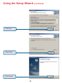
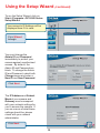
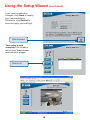
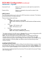
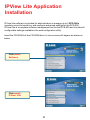
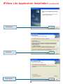
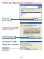
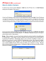
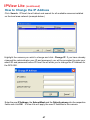
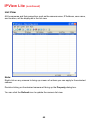
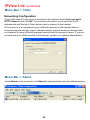
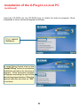
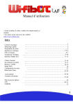
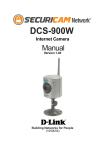
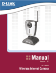
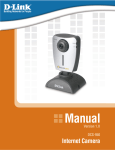
IPView Lite Application Installation
Click Next
If your sound card or video card has
not passed Windows Logo testing,
this window will appear.
Click Continue Anyway
If there are previously installed
target files that are newer than the
source files, do NOT overwrite them.
Click No
39
(continued)
IPView Lite Application Installation
(continued)
Click Finish
After successfully installing the IPView Lite, the application program for the DCS-900
is automatically installed to \Programs\IPViewLite Directory.
To start running the IPView Lite click on windows Start > Programs > IPViewLite >
IPViewLite.
Enter the default User Name:
admin into the respective field
and click on OK to log into the
application.
Click OK
40
IPView Lite Application Installation
(continued)
Once logged in, the IPView Lite application is executed and the IPView Lite interface
will appear in the default List View format:
41
IPView Lite
This section describes the operation of the IPView Lite application User Interface with
detailed procedures for using the application.
IPView Lite
IPView Lite allows you to manage your cameras by enabling you to search, configure
and preview all the DCS-900s from one location.
It is designed with a user-friendly interface for ease of control and navigation.
How to Change the Password
Change Password
When IPView Lite is used for the first time, it is highly recommended that the Administrator
change the User Name and Password for security purposes. Once the User Name
and Password are defined, only the Administrator has access to the management of
IPView Lite applications. This procedure should be done as soon as possible to prevent
unauthorized usage of the IPView Lite application.
To change the administrator User Name and Password, select Tools > Options. The
Options dialog box will appear (see below).
Enter a User Name and enter the Password twice. Once all the new details are
entered click OK.
42
IPView Lite (continued)
How to Add a Camera
To add a new camera select Camera > Add from the IPView Lite. An Add Camera
dialog box will appear. (See below.)
Enter the IP Address of the camera in the specified field and click Add. If the IP Address
is entered incorrectly or if you have a bad network connection, a dialog box will appear
to notify you of the error. To add cameras in IPView Lite, check that you have your
network configured correctly. To add a remote camera, you need to have Internet access.
If you are unsure of the IP Address of the camera, you can click on Browse to search
for cameras on your local area network. The Browse Camera dialog box will appear
with a blank screen. (See below.)
Note: Only cameras on your local area network can be located using Browse
in IPView Lite. If you want to add a camera via the Internet, you must enter in
a physical IP Address. Remember that if your camera is behind a router, you
will need to enter your router’s WAN IP followed by a colon, then the port number
that is assigned to your camera, i.e. 68.2.34.156:800, where 68.2.34.156 is
your router’s WAN IP and :800 is the port that your camera is using. Please
refer to the DCS-900 Configuration, Installation Behind a Router section of this
manual for details on P.23.
43
IPView Lite (continued)
How to Add a Camera
Click on Search. IPView Lite will detect and search for all the available cameras that
are installed on the local area network.
Highlight the camera you wish to add and click on Add. The Add Camera dialog box
will appear once again with the IP Address entered. Click on Add. The camera will
automatically be added into the IPView Lite list view.
Alternatively, you can double-click on the camera you wish to add and the Add Camera
dialog box will appear once again with the IP Address entered. Click on Add, and the
camera will automatically be added into the IPView Lite list view.
192.168.0.20
44
IPView Lite (continued)
How to Add/Delete a Camera
If the Login Camera dialog box appears, make sure to enter the correct Username
and Password. Click OK. The camera will be added into IPView Lite, in list format. If
the Username and Password are entered incorrectly, the camera will not be added
into IPView Lite.
The Login Camera dialog box will appear regardless of password settings on the camera.
If you have not created a password yet, leave both fields blank and press enter.
How to Delete a Camera
To delete a camera you must highlight the camera you wish to delete from the IPView
Lite list view format. From the menu bar select Camera > Delete. A Delete Camera
dialog box will appear. Click Yes to delete the camera, or click No if you do not wish to
delete the camera.
List view
Click Yes.
45
IPView Lite (continued)
How to Change the IP Address
Changing the IP Address
To change an IP Address for a camera, select Camera > Add. An Add Camera dialog
box will appear (see below).
Click on Browse. The Browse Camera dialog box will appear with a blank screen (see
below).
46
IPView Lite (continued)
How to Change the IP Address
Click Search. IPView Lite will detect and search for all available cameras installed
on the local area network (example below.)
Highlight the camera you wish to change and click Change IP. If you have already
changed the administrator user ID and password, you will be prompted to enter your
admin ID and password before IPView Lite will allow you to change the IP Address for
the DCS-900.
Enter the new IP Address, the Subnet Mask and the Default gateway into the respective
fields and click OK. IPView Lite will apply the new IP Address to the camera.
47
IPView Lite (continued)
How to Format the Camera view
From the menu bar select View > 4 Cameras. (See below.)
The icon on the upper left corner of the screen will appear with the camera number
that is being displayed.
To return to the IPView Lite list view , click on the icon located on the upper left corner of
the screen and a case sensitive menu will appear. Select List and the viewing image will
return to the list view format.
A maximum of 4 cameras can be viewed simultaneously with IPView Lite.
48
IPView Lite (continued)
How to Rotate the Video view
In View Mode format, click on the icon located on the upper left corner of the screen and
a pop-up menu will appear.
Once you click Rotate Right or Rotate Left in the menu, the video will rotate 90 degrees
to the right or left.
How to take a Snap-Shot with the Camera
To take a snap shot with the camera, you must highlight the camera you wish to use
from the IPView Lite list view format. From the menu bar select Camera > Snap
shot. A Save Image dialog box will appear for you to save the snap shot picture.
Alternatively, select from the viewing mode either 1 or 4 cameras. Click on the icon
located on the upper left corner of the screen. A case sensitive menu will appear. Select
the Snap shot icon. A Save Image dialog box will appear for you to save the snap shot
picture.
49
IPView Lite (continued)
How to Start Recording
To start recording with a camera you must highlight the camera you want to use from the
list view format. From the menu bar select Camera > Start. An AVI file will appear in
your IPView Lite folder to save the recorded videos.
Alternatively, in the viewing mode (using either 1 or 4 cameras), right-click on the icon
located on the upper left corner of the screen. A case sensitive menu will appear. Select
the Start icon. An AVI file will appear in your IPView Lite folder to save the recorded
videos.
Note :
You must stop recording before changing any camera settings.
How to Stop Recording
To stop recording with a camera, you must highlight the camera you wish to stop from the
list view format. From the menu bar select Camera > Stop. The recording function will be
stopped.
The other alternative is to click the icon located on the upper left corner of the screen
under the viewing mode of either 1 or 4 cameras; a case-sensitive menu will appear.
Select Stop. The recording will now cease.
50
IPView Lite (continued)
Camera Property Settings > General
Once you have completed the initial configuration of the DCS-900 using the Web-based
interface, you can review or change your configuration using either the Web-based
configuration utility or the Property Settings in the DCS-900 IPView Lite.
To access the Property Settings menu, select Camera > Property from the main menu
or double-click on the camera link from within the list view. The Camera Property box
will appear which allows for Web Configuration settings and upgrading firmware. Select
the desired options from the tab selections to configure the camera.
General
Allows settings for the camera name, location and administrator information such as
administrator ID and password. Please refer to the DCS-900 Configuration section under
Advanced – System for further details (P.18.)
51
IPView Lite (continued)
Camera Property Settings > IP Assignment
IP Assignment
If you need to change your IP Address, select the IP Address tab in the Camera
property window. There are two options: Manually Assign or Assign Automatically
Using. Please refer to the DCS-900 Configuration section: Advanced – System for
further details (P.18).
52
IPView Lite (continued)
Camera Property Settings > DNS
DNS
DNS (Domain Name System) server is an Internet service that translates domain names
into IP Addresses. Please refer to the DCS-900 Configuration section under Advanced
- System for further details (P.18).
36.137.143.135
4.3.2.1
53
IPView Lite (continued)
Camera Property Settings > Misc, Image
Misc
Configure the LED Control, ActiveX control location, and second port in this menu. Please
refer to the DCS-900 Configuration section under Advanced– System for further details
(P.18).
Image
Brightness, contrast, hue, resolution, compression, frame rate, and light frequency can
be adjusted for your camera. Please refer to the DCS-900 Configuration section under
Advanced – Video for further details (P.28).
54
IPView Lite (continued)
Camera Property Settings > Users
Users
Set up user accounts with user name and password for camera access. Please refer to
the DCS-900 Configuration Setting under Tools-Admin for more detailed information
(P.30).
To add a user click on the Add icon and the Add User dialog box will appear. Enter the
User Name and Password into the specific field.
To delete a user, select the user and click Delete.
55
IPView Lite (continued)
Camera Property Settings > Date/Time
Date/Time
Set the camera’s time and date to provide correct time information for remote users by
selecting Synchronized with Time Server or Set Manually. Please refer to the
DCS-900 Configuration section under Tools-Time for further details (P.32).
56
IPView Lite (continued)
Camera Property Settings > Information
Information
Displays information about the camera such as the model, firmware version, MAC address,
and IP address. Please refer to the DCS-900 Configuration section under Status for
further details (P.34).
57
IPView Lite (continued)
Camera Property Settings > Tools
Tools
Reset the camera and update firmware in this section. Please refer to the DCS-900
Configuration section under Tools-Default for further details (P.34).
Upgrade Firmware
Enter the full path of the firmware binary file name in the Update Firmware field or you
can click on the Browse button to select the file. Once the firmware file is entered click
on the Update button to proceed with the update process. Once completed, click OK.
Warning
The download firmware procedure cannot be interrupted. If the
network connection is broken during the download procedure it
could cause serious damage to the Internet Camera.
58
IPView Lite (continued)
Camera Property Settings > Recording
Recording Options
Manual Recording
If the Manual Recording option is chosen, you must manually start recording in the
List view of the DCS-900 in the Menu Bar or by clicking on the Record Icon. Choose
Round the Clock to enable the DCS-900 to record all video frames continuously to
your hard drive. Larger files will be generated if Round-the-Clock Manual Recording is
chosen. The Dynamic Recording option uses movements to record only relevant
video frames and will generate much smaller files to save your hard disk drive space.
59
IPView Lite (continued)
Camera Property Settings > Recording
Scheduled Recording
Select Schedule Recording to record based on specific times and dates. Click Schedule
Setting to set the time and date for recording your files. Select By Date and enter in the
dates, Start, and Stop Times. The camera will start to record according to the specified
date and time period entered. Select By Weekday to indicate specific days to record
and the time period. Larger files will be generated if Round-the-Clock Manual Recording
is chosen. The Dynamic Recording option uses movements to record relevant video
frames and will generate much smaller files to save your hard disk drive space.
60
IPView Lite (continued)
Camera Property Settings > Recording
Motion Trigger Recording
Checking Motion Trigger Recording enables the DCS-900 to record based on motion.
When this option is selected and the camera detects motion within the range of the
viewing window, recording will be triggerd. Recording will continue until no motion is
detected. Click on Sensitivity Setting to set the sensitivity levels for the DCS-900.
61
IPView Lite (continued)
Camera Property Settings > Recording
File Options
You can adjust the maximum file size by clicking on By File Size from the Recording
File Options field. The file size must be between 10 and 50MB. If the recorded video files
reach the file size allocated, video images will be recorded into another file automatically.
Be sure to click Apply to save your settings, then click OK to exit this screen.
Note: If you are using Windows Media Viewer to view your recorded videos, make sure
that you have the most up-to-date version in order to view the videos correctly.
File Path
The software will create a folder in the Recording File Path specified and record the
video images with the file name by date and time. Multiple file paths can be specified to
store your video images. The current path where recorded images are being stored is
designated as “Working”. Once this path has reached full capacity, the images will then
be stored in the next designated file path. To change file paths, highlight the file path and
double-click to select a new drive/directory to store your video images.
The screen below will appear. Click Browse to select a drive/directory, and place a
check mark in the Path box to enable the drive/directory for use. Click OK to save your
changes.
62
IPView Lite (continued)
Menu Bar
The menu bar makes it easier to navigate IPView Lite. All Management functions can
be accessed from the menu bar.
Menu Bar > File
New > Opens a new camera list. Cameras must then be added to the list for
configuration
Open > Opens saved camera lists.
Save/Save As > Saves your current list of cameras and configurations.
Exit > Exits the IPView Lite Application.
.
63
IPView Lite (continued)
Menu Bar > View
View on the menu bar provides users with management capabilities for Columns,
List, Camera and Refresh. You can view the Camera in 1 Camera or 4 Camera
mode. The View menu bar is pictured below.
Columns
When Columns is launched, a dialog box will appear displaying the Column
Settings. Select the columns that you wish to appear in the List View as illustrated
below.
Viewing Format
You can view the format in List view. The List viewing format allows easy management
and control of each camera.
64
IPView Lite (continued)
List View
All the cameras and their properties, such as the camera name, IP Address, user name,
and location, will be displayed in the list view.
Note:
Right click on any camera to bring up a menu of actions you can apply to the selected
camera.
Double-clicking on the desired camera will bring up the Property dialog box.
You can click the Refresh icon to update the camera list view.
65
IPView Lite (continued)
Menu Bar > Camera, Tools
Camera on the menu bar provides options to manage the camera. Add up to 4 additional
Cameras for viewing. The Camera menu also allows you to Delete a camera, manage
the Property, Enable real-time video capture, or take a Snap shot image.
Enable Function
By default, the video image is enabled. There will be a check next to the Enable command
to show that the Enable function is working. To disable the real-time image select
Camera > Enable and the real-time video image will stop and shutdown.
Menu Bar > Tools
Tools on the menu bar allows you to change account information and system
configuration. From the menu bar, select Tools > Options.
66
IPView Lite (continued)
Menu Bar > Tools
Account
The account menu is for administrators to change user name and password.
System Configuration
.
This menu allows you to set overwrite options to overwrite old recorded files with new
recorded files. Check the Load Last Configuration When Program Starts to load all
your configured settings each time you run IPView Lite. It is highly recommended
that you select this option to save your camera settings in IPView Lite.
In order to allow old video files to be overwritten and replaced by new recorded files, place
a check mark in the Recycle Box and click on By HDD Reserved Space or By Time.
The Single HDD Reserved Space field refers to the amount of space left on your drive
before overwrite takes place. For instance if you enter 1000 MB, and your total hard drive
space is 3000 MB, as soon as your drive reaches 2000 MB capacity, your files will be
67
IPView Lite (continued)
Menu Bar > Tools
overwritten. You can specify between 500MB to 5GB hard drive reserve space. Click on
By Time to overwrite old files with new files once the time frame that you specify has
been reached.
Clicking on By HDD Reserved Space
allows new files to overwrite old files. You
can reserve 500MB to 5GB HDD for the
program.
Click on By Time (Time: 1-240 Hours) to
overwrite old files with new files once the
time frame that you specify has been
reached.
Note: Selecting the Recycle option will disable the Recording File Path Settings in
the Recording menu.
68
IPView Lite (continued)
Menu Bar > Tools
Networking Configuration
If your LAN uses a Proxy server to connect to the Internet, select Use a proxy for
HTTP Protocol, and click OK. If you choose this option, you must enter the IP
address and port that your Proxy server uses to connect to the Internet.
A Proxy server is a computer on your LAN that connects to the Internet without
compromising the security of your internal network. A proxy server is normally used
on a network to more efficiently manage Internet traffic for groups of users. If you are
not sure how your LAN connects to the Internet, contact your system administrator.
Menu Bar > About
Under About on the menu bar, click About for camera details such as software version.
69
IPView Lite Icon Description
Open a new file. The hot key is Ctrl+N.
Open an existing file. The hot key is Ctrl+O.
Save a file. The hot key is Ctrl+S.
List view format. The hot key is Ctrl+F1.
1 Camera view format. The hot key is Ctrl+F3.
4 Camera view format. The hot key is Ctrl+F4.
Refresh IPView Lite application. The hot key is F12.
Add a camera. The hot key is Shift+Ins.
Delete a camera. The hot key is Del.
Property setting to configure the camera. The hot key is F2.
Snap shot to capture a single still image. The hot key is F5.
Start recording video image. Alternatively the hot key is F7.
Stop recording video image. Alternatively the hot key is F9.
Options to modify the User Name and Password for IPView Lite.
The hot key is F10.
70
IPView Lite (continued)
Context Sensitive Menu
In List View format, highlight a camera and right-click to bring up a context sensitive
menu for features such as Add, Delete, Property, Enable, and Snap shot and Start/
Stop recordings.
In View mode format click on the icon located on the upper left corner of the screen and
a case sensitive menu will appear (see below).
These features will be available: Enable, Rotate Right, Rotate Left, Snap Shot, Start,
List, 1 Camera or 4 Cameras, Previous Page and Next Page.
71
Uninstall IPView Application
Click on windows Start Menu / Programs / IPView / Uninstall IPView. A new
prompt screen will be displayed like the one below confirming the removal.
Choose the option that you want and click Next to continue the process or click on
Cancel to reject the uninstall process.
After you click on Next, a Confirm Uninstall dialog box will appear. Click OK to
continue the process.
72
Uninstall IPView Application
(continued)
The InstallShield Wizard prompt will appear. Click Finish to complete the uninstallation
procedure.
73
Appendix A
Frequently Asked Questions
Internet Camera Features
Q: What is an Internet Camera?
A:The Internet Camera is a standalone system connecting directly to an Ethernet or
Fast Ethernet network and supported by the wireless transmission based on the IEEE
802.11b standard. It is different from the conventional PC Camera, the Internet Camera
is an all-in-one system with built-in CPU and web-based solutions providing a low cost
solution that can transmit high quality video images for monitoring. The Internet Camera
can be managed remotely, accessed and controlled from any PC/Notebook over the
Intranet or Internet via a web browser.
Q: What is the maximum number of users that can be allowed to access DCS900 simultaneously?
A: Maximum number of users that can log onto the Internet Camera at the same time is
8. Please keep in mind the overall performance of the transmission speed will slow down
when multiple users are logged on.
Q: What algorithm is used to compress the digital image?
A: The Internet Camera utilizes JPEG image compression technology to provide high
quality images. JPEG is a standard for image compression and can be applied to various
web browser and application software without the need to install extra software.
Q: Can I capture still images from the Internet Camera?
A: Yes you are able to capture still images with the snapshot function from the IPView
Lite application supplied with the Internet Camera CD-ROM. You may also use the
first page that shows up when you type in the IP Address of the camera. When
viewing this page, press the “refresh” button on your web browser to update the
image. Please refer to the User’s Guide for detailed information.
74
Frequently Asked Questions (continued)
Internet Camera Installation
Q: Can the Internet Camera be used outdoors?
A: The Internet Camera is not weatherproof. It needs to be equipped with a weatherproof
case to be used outdoors and it is not recommended.
Q: What network cabling is required for the Internet Camera?
A: The Internet Camera uses Category 5 UTP Twisted-pair cable allowing 10 Base-T and
100 Base-T networking.
Q: Can the Internet Camera be setup as a PC-cam on the computer?
A: No, the Internet Camera is used only on Ethernet and Fast Ethernet network or
supported by wireless transmission. The D-Link DSB-C110, DSB-C310 can be used as
a PC Camera (Webcam).
Q: Can the Internet Camera be connected on the network if it consists of only
private IP Addresses?
A: Yes, the Internet Camera can be connected to a LAN with private IP Addresses.
Q: Can the Internet Camera be installed if a firewall exists on the network?
A: If a firewall exists on the network, port 80 is open for ordinary data communication.
You will need to do port forwarding by opening a port to the camera. Please refer to your
firewall’s product manual for detailed instructions.
Troubleshooting
Q: I cannot access the Internet Camera from a web browser.
A1: The possible cause might be the IP Address for the Internet Camera is already being
used by another device. To correct the possible problem, you need to first disconnect
the Internet Camera from the network. Then run the PING utility (follow the instructions
in Appendix B - PING Your IP Address.)
75
Troubleshooting
(continued)
Internet Camera Installation
A2: Another possible reason is the IP Address is located on a different subnet. To fix the
problem, run the PING utility (follow the instructions in Appendix B - PING Your IP
Address). If the utility returns “request timed out” or similar, the finding is probably
correct, then you should proceed as follows:
In Windows 98SE and 2000, check that the IP Address of the Internet Camera is within
the same subnet as your workstation.
!
Click Start, Setting, Control Panel, and the Network icon.
!
Select TCP/IP from the Network dialog box and from the TCP/IP Properties
dialog box click on Specify an IP address.
!
If the Internet Camera is situated on a different subnet than your workstation, you
will not be able to set the IP Address from this workstation. To verify, make sure
the first 3 sections of the IP Address of the Internet Camera corresponds to the
first 3 sections of the workstation. Therefore the IP Address of the Internet Camera
must be set from a workstation on the same subnet.
A3: Other possible problems might be due to the network cable. Try replacing your
network cable. Test the network interface of the product by connecting a local computer
to the unit, utilizing a standard Crossover Cable. If the problem is not solved, the Internet
Camera might be faulty.
Q: Why does the Power LED not light up constantly?
A: The power supply used might be at fault. Confirm that you are using the provided
power supply, which is DC 5V, for the Internet Camera and verify that the power supply
is well connected.
Q: Why does the LAN LED not light up properly?
A1: There might be a problem with the network cable. To confirm that the cables are
working, PING the address of a known device on the network. If the cabling is OK and
your network is reachable, you should receive a reply similar to the following (…bytes =
32 time = 2 ms).
A2: The network device utilized by the Internet Camera is not functioning properly, such
as hubs or switches. Confirm the power for the devices are well connected and functioning
properly.
76
Troubleshooting
(continued)
Internet Camera Installation
Q: Why does the Internet Camera work locally but not externally?
A1: Might be caused from the firewall protection. Check the Internet firewall with your
system administrator. The firewall may need to have some settings changed in order for
the Internet Camera to be accessible outside your local LAN.
A2: Make sure that the Internet Camera isn’t conflicting with any web server you may
have running on your network.
A3: The default router setting might be a possible reason. Check that the configuration
of the router settings allow the Internet Camera to be accessed outside your local LAN.
Q: Why does a series of broad vertical white lines appear through out the image?
A: It could be that the CMOS sensor (a square panel situated behind the lens that
measures the light signals and changes it into a digital format so your computer can
present it into an image that you are familiar with) has become overloaded when it has
been exposed to bright lights such as direct exposure to sunlight or halogen lights.
Reposition the Internet Camera into a more shaded area immediately as prolonged
exposure to bright lights will damage the CMOS sensor.
Q: The focus on the Internet Camera is bad, how can I correct it?
A1: Adjust the Internet Camera focus manually as described in “Adjusting the Internet
Camera Focus” in the Appendix section of this manual on P.85.
Q: Noisy images occur. How can I solve the problem?
A1: The video images might be noisy if the Internet Camera is used in a very low light
environment. To solve this issue you need more lighting.
77
Troubleshooting (continued)
Q: The images are poor quality, how can I improve the image quality?
A1: Make sure that your computers display properties are set to at least 15-bit color.
Using 16 or 256 colors on your computer will produce dithering artifacts in the image,
making the image look as if it is of poor quality.
A2: The configuration on the Internet Camera image display is incorrect. Through the
Web Configuration Video section of the web management you need to adjust the image
related parameters for improved images such as: brightness, contrast, hue and light
frequency. Please refer to the Web Configuration section for detailed information.
Q: There are no images available through the web browser?
A1: The ActiveX might be disabled. If you are viewing the images from Internet Explorer
make sure ActiveX has been enabled in the Internet Options menu. Alternatively, you
can use the Java Applet for viewing the required images.
A2: If you are using Windows XP, please make sure that you have downloaded Java and
installed it properly.
A3: Make sure that your web browser supports Java. If you are using Internet Explorer or
Netscape Navigator with a version number of lower than 4, then you will need to upgrade
your web browser software in order to view the streaming video transmitted by the Internet
Camera.
Appendix B
How to PING Your IP Address
The PING (Packet Internet Groper) command can determine whether a specific IP Address
is accessible by sending a packet to the specific address and waiting for a reply. It is a
very useful tool to confirm if the IP Address conflicts with the Internet Camera over the
network.
Follow the step-by-step procedure below to utilize the PING command.
78
How to Ping your IP Address (continued)
Start a DOS window Start>Program>Accessories>Command Prompt
Type ping x.x.x.x, where x.x.x.x is the IP Address of the Internet Camera.
1) A successful connection to the camera will be indicated by 4 reply statements
(above). If you fail to connect to your camera you will see the following:
2) Check to see if you have entered your camera’s IP Address correctly or reassign yor
camera’s IP Address.
79
Time Zone Table
GMT stands for Greenwich Mean Time, which is the global time that all time zones
are measured from.
80
Time Zone Table (continued)
81
Xplug Control Installation
Installation to a Web Server
Important Information
It is highly recommended to install the Xplug Control application to the Web Server
for Internet Explorer 5.0. It must be installed to a Public Domain with a Fixed IP
Address.
1. Installation:
Copy the “xplug.ocx” file to any Web Server table. Note the web address of the
file location so that you can use it in the next step.
2. Configuration:
From the Web Configuration menu, select “System” and under the “Loading
ActiveX From” input web server location, type:
http://www.web server location.com/.
Once the settings are completed, you should now be able to access the Internet Camera
from the web browser by selecting ActiveX mode.
82
Installation of the X-Plug to a Local PC
(continued)
Insert the CD-ROM into the CD-ROM drive to initiate the auto-run program. Once
completed, a menu screen will appear as follows:
Click Install
Software.
To install Xplug Control click on the
“Install X Plug” button to activate the
installation procedure for the plug-in
program. Once executed a prompt
will appear requesting the input of the
desired language selection. Make the
desired selection and click on “OK”
to continue.
83
Installation of the X-Plug to a Local PC
(continued)
Click Next
Click Yes
84
Installation of the X-Plug to a Local PC
(continued)
Click Finish
Adjusting the Camera Focus
To help you get the best image quality, keep in mind that while adjusting the DCS-900
focus you can preview the image quality from your Web browser.
Camera Lens
Adjust by turning
clockwise or
counter-clockwise
85
Adjusting the Camera Focus (continued)
Note:
You can further adjust the Internet Camera’s image quality through the
Web Configuration under Advanced-Video. Please refer to the Web
Configuration section for further details.
Warning
Direct exposure to sunlight may cause permanent damage to the CMOS
sensor. Therefore do not expose the Internet Camera’s lens directly to
sunlight. When operation is required in glaring light environment, it is recommended to use an iris lens.
The Internet Camera is designed for indoor usage and if your application
requires prolonged exposure to sunlight, a sun visor is recommended to
protect the Internet Camera.
86
Technical Specifications
Video specification
Resolution:
Sensor:
Gain control:
Exposure:
White Balance:
Shutter:
Minimum Illumination:
Focal Length:
Aperture:
640 x 480 pixel
1/3" color CMOS sensor
Automatic
Automatic
Automatic
Electronics 1/60 ~ 1/15000 sec
[email protected], 3000K color
6.0 mm
F=1.8
Image (Video Setting)
Image compression:
Frame rate:
Compression Rate selection:
Frame rate setting:
Video resolution:
Brightness control:
Contrast control:
Hue control:
JPEG
20fps@SIF, 10fps@VGA
5 level (Very Low, Low, Medium, High, Very High)
1, 5, 7, 15, 20, auto (depends on the video format)
320x240, 640x480
Range 1- 128
Range 1- 128
Range 1- 128
System Hardware
LAN Connector:
One RJ-45 port to connect to 10/100Mbps
Ethernet, auto-sensed
87
Technical Specifications (continued)
LED Indicator:
Power LED (Green)
LAN Activity LED (Orange)
(Normal / Off / Dummy)
Power Supply:
Power Communication:
DC 5V/2.5A, switching type
4.5 Watt (900mA x 5V)
Communication Support
Communication:
Communication protocol:
10/100Mbps Ethernet and Fast Ethernet only
HTTP, TCP/IP, UDP, ARP,
ICMP, BOOTP, RARP, DHCP, PPPoE
Web Configuration Requirements:
•
•
•
•
•
•
Internet Explorer 5.0 or above or Netscape 6.0 or above
CPU: Pentium II, 266 MHz or above
Memory Size: 32 MB (64 MB recommended)
VGA card resolution:
800x600 or above
ActiveX Control requires IE4.0 or above (Windows)
Java Applet requires IE4.0 or above (Windows/Mac) or Netscape 4.0 or above
(Windows/Mac/Linux)
PC Requirements for IPView Lite:
•
•
•
Windows XP, Windows 2000, Windows Me, Windows 98SE
Pentium III, 450 MHz CPU or above
128 MB (256 MB Recommended)
EMI & Safety
FCC, CE, VCCI
88