1
IPD Vision Appliances
VA61
GigE Camera Vision Appliance
User’s Reference Manual
405-00022-00
Rev. 00
16 October 2007
VA61 GigE Camera Vision Appliance User’s Reference Manual
Document Number 405-00022-00
Revision 00; 16 October 2007
CopyrightE2007 DALSA Corporation.
All rights reserved.
Printed in the United States of America.
All copyrights in this manual, and the hardware and software described in it, are the exclusive property of DALSA Corporation and its licensors. Claim of copyright does not imply waiver of DALSA Corporation or its licensor’s other rights in the work. See the following Notice of
Proprietary Rights.
NOTICE OF PROPRIETARY RIGHTS
This manual and the related hardware and software are confidential trade secrets and the property of DALSA Corporation and its licensors.
Use, examination, reproduction, copying, transfer and/or disclosure to others of all or any part of this manual and the related documentation
are prohibited except with the express written consent of DALSA Corporation.
The information in this document is subject to change without notice. DALSA Corporation makes no representations or warranties
with respect to the contents of this manual and specifically disclaims any implied warranties of merchantability or fitness for a particular purpose. DALSA Corporation assumes no responsibility for errors or omissions in this document.
iNspect, iLabel, Sherlock, and the DALSA logo are trademarks of DALSA Corporation.
Camera Configurator is a registered trademark of DALSA Corporation.
All other trademarks are the property of their respective owners.
DALSA IPD
Email: [email protected]
http://www.goipd.com
IPD Headquarters
700 Technology Park Drive
Billerica, MA, USA 01821
Tel 1.978.670.2002 Fax 1.978.670.2010
405-00022-00
VA6x User’s Reference
Table of Contents
1. Introduction . . . . . . . . . . . . . . . . . . . . . . . . . . . . . . . . . . . . . . . . . . . . . . . . . . . . . . . . . .
Overview . . . . . . . . . . . . . . . . . . . . . . . . . . . . . . . . . . . . . . . . . . . . . . . . . . . . . . . . . .
About This Manual . . . . . . . . . . . . . . . . . . . . . . . . . . . . . . . . . . . . . . . . . . . . . . . . . .
2. Before You Begin . . . . . . . . . . . . . . . . . . . . . . . . . . . . . . . . . . . . . . . . . . . . . . . . . . . . . .
Product Verification . . . . . . . . . . . . . . . . . . . . . . . . . . . . . . . . . . . . . . . . . . . . . . . . . .
Handling and Operating Precautions . . . . . . . . . . . . . . . . . . . . . . . . . . . . . . . . . . . . .
ElectroStatic Discharge . . . . . . . . . . . . . . . . . . . . . . . . . . . . . . . . . . . . . . . . . . .
User Service Warning . . . . . . . . . . . . . . . . . . . . . . . . . . . . . . . . . . . . . . . . . . . .
Environmental Requirements . . . . . . . . . . . . . . . . . . . . . . . . . . . . . . . . . . . . . .
3. Support and Maintenance . . . . . . . . . . . . . . . . . . . . . . . . . . . . . . . . . . . . . . . . . . . . . . .
Warranty . . . . . . . . . . . . . . . . . . . . . . . . . . . . . . . . . . . . . . . . . . . . . . . . . . . . . . . . . .
Support and Authorized Return Information . . . . . . . . . . . . . . . . . . . . . . . . . . . . . . .
Documentation . . . . . . . . . . . . . . . . . . . . . . . . . . . . . . . . . . . . . . . . . . . . . . . . .
IPD Website . . . . . . . . . . . . . . . . . . . . . . . . . . . . . . . . . . . . . . . . . . . . . . . . . . .
Factory Support . . . . . . . . . . . . . . . . . . . . . . . . . . . . . . . . . . . . . . . . . . . . . . . . .
Maintenance . . . . . . . . . . . . . . . . . . . . . . . . . . . . . . . . . . . . . . . . . . . . . . . . . . . . . . .
Regulatory Compliance . . . . . . . . . . . . . . . . . . . . . . . . . . . . . . . . . . . . . . . . . . . . . . .
FCC Compliance Statement . . . . . . . . . . . . . . . . . . . . . . . . . . . . . . . . . . . . . . .
Declaration of Conformity of a Class B Digital Device
According to the FCC Rules . . . . . . . . . . . . . . . . . . . . . . . . . . . . . . . . .
European Declaration of Conformity . . . . . . . . . . . . . . . . . . . . . . . . . . . . . . . .
4. Product Overview . . . . . . . . . . . . . . . . . . . . . . . . . . . . . . . . . . . . . . . . . . . . . . . . . . . . .
Product Description . . . . . . . . . . . . . . . . . . . . . . . . . . . . . . . . . . . . . . . . . . . . . . . . . .
Typical Applications . . . . . . . . . . . . . . . . . . . . . . . . . . . . . . . . . . . . . . . . . . . . .
Components . . . . . . . . . . . . . . . . . . . . . . . . . . . . . . . . . . . . . . . . . . . . . . . . . . . . . . . .
5. Installation . . . . . . . . . . . . . . . . . . . . . . . . . . . . . . . . . . . . . . . . . . . . . . . . . . . . . . . . . . .
Pre-Installation Checks . . . . . . . . . . . . . . . . . . . . . . . . . . . . . . . . . . . . . . . . . . . . . . .
Interface Specifications . . . . . . . . . . . . . . . . . . . . . . . . . . . . . . . . . . . . . . . . . . . . . . .
Camera Connections . . . . . . . . . . . . . . . . . . . . . . . . . . . . . . . . . . . . . . . . . . . . .
Camera Settings . . . . . . . . . . . . . . . . . . . . . . . . . . . . . . . . . . . . . . . . . . . . . .
GigE Camera Video Data Cable . . . . . . . . . . . . . . . . . . . . . . . . . . . . . . . . . .
Camera Control & Power Cable . . . . . . . . . . . . . . . . . . . . . . . . . . . . . . . . . .
Network Connection . . . . . . . . . . . . . . . . . . . . . . . . . . . . . . . . . . . . . . . . . . . . .
1
1
1
2
2
2
2
2
3
4
4
4
4
4
4
5
5
5
5
5
6
6
6
7
8
8
8
9
9
10
10
12
Rev 00; 16 October 2007
iii
VA6x User’s Reference
405-00022-00
Serial Port Connection . . . . . . . . . . . . . . . . . . . . . . . . . . . . . . . . . . . . . . . . . . .
Industrial I/O Connections . . . . . . . . . . . . . . . . . . . . . . . . . . . . . . . . . . . . . . . .
Input Electrical Specifications . . . . . . . . . . . . . . . . . . . . . . . . . . . . . . . . . . .
Output Electrical Specifications . . . . . . . . . . . . . . . . . . . . . . . . . . . . . . . . . .
I/O Breakout Options . . . . . . . . . . . . . . . . . . . . . . . . . . . . . . . . . . . . . . . . . . . .
Standard Terminal Breakout (A-IOB-011) . . . . . . . . . . . . . . . . . . . . . . . . . .
Optional Isolation Breakout (A-IOB-100) . . . . . . . . . . . . . . . . . . . . . . . . . .
Solution Switching Using I/O . . . . . . . . . . . . . . . . . . . . . . . . . . . . . . . . . . . . . .
Status LEDs and RESET Switch . . . . . . . . . . . . . . . . . . . . . . . . . . . . . . . . . . . . . . . .
iNspect & iLabel function . . . . . . . . . . . . . . . . . . . . . . . . . . . . . . . . . . . . . .
Sherlock function . . . . . . . . . . . . . . . . . . . . . . . . . . . . . . . . . . . . . . . . . . . . .
Mounting Options . . . . . . . . . . . . . . . . . . . . . . . . . . . . . . . . . . . . . . . . . . . . . . . . . . .
VA61 Chassis . . . . . . . . . . . . . . . . . . . . . . . . . . . . . . . . . . . . . . . . . . . . . . . .
Cameras . . . . . . . . . . . . . . . . . . . . . . . . . . . . . . . . . . . . . . . . . . . . . . . . . . . .
Breakout Module . . . . . . . . . . . . . . . . . . . . . . . . . . . . . . . . . . . . . . . . . . . . .
Installation . . . . . . . . . . . . . . . . . . . . . . . . . . . . . . . . . . . . . . . . . . . . . . . . . . . . . . . . .
Camera Configuration . . . . . . . . . . . . . . . . . . . . . . . . . . . . . . . . . . . . . . . . . . . . . . . .
Troubleshooting . . . . . . . . . . . . . . . . . . . . . . . . . . . . . . . . . . . . . . . . . . . . . . . . . . . . .
Appendix A. Connectors and Pinouts . . . . . . . . . . . . . . . . . . . . . . . . . . . . . . . . . . . . . . . .
Camera Control Connectors . . . . . . . . . . . . . . . . . . . . . . . . . . . . . . . . . . . . . . . . . . .
Power Connector . . . . . . . . . . . . . . . . . . . . . . . . . . . . . . . . . . . . . . . . . . . . . . . . . . . .
I/O Connector . . . . . . . . . . . . . . . . . . . . . . . . . . . . . . . . . . . . . . . . . . . . . . . . . . . . . .
Ethernet and USB Connectors . . . . . . . . . . . . . . . . . . . . . . . . . . . . . . . . . . . . . . . . . .
Display Connector . . . . . . . . . . . . . . . . . . . . . . . . . . . . . . . . . . . . . . . . . . . . . . . . . . .
Serial Connector . . . . . . . . . . . . . . . . . . . . . . . . . . . . . . . . . . . . . . . . . . . . . . . . . . . .
Appendix B. Staging and Presentation . . . . . . . . . . . . . . . . . . . . . . . . . . . . . . . . . . . . . . .
An Example . . . . . . . . . . . . . . . . . . . . . . . . . . . . . . . . . . . . . . . . . . . . . . . . . . . . . . . .
Part-in-Place Sensor . . . . . . . . . . . . . . . . . . . . . . . . . . . . . . . . . . . . . . . . . . . . . . . . .
Reducing Blurring Caused by Part Motion . . . . . . . . . . . . . . . . . . . . . . . . . . . . . . . .
Progressive Scan Cameras . . . . . . . . . . . . . . . . . . . . . . . . . . . . . . . . . . . . . . . . . . . . .
Strobe Lighting . . . . . . . . . . . . . . . . . . . . . . . . . . . . . . . . . . . . . . . . . . . . . . . . . . . . .
Using Contact Closures . . . . . . . . . . . . . . . . . . . . . . . . . . . . . . . . . . . . . . . . . . . . . . .
Using Photo-Sensors . . . . . . . . . . . . . . . . . . . . . . . . . . . . . . . . . . . . . . . . . . . . . . . . .
Appendix C. Sherlock Digital I/O Assignments . . . . . . . . . . . . . . . . . . . . . . . . . . . . . . . .
Appendix D. Non-Standard Options . . . . . . . . . . . . . . . . . . . . . . . . . . . . . . . . . . . . . . . . .
Current Sourcing PNP Output . . . . . . . . . . . . . . . . . . . . . . . . . . . . . . . . . . . . . . . . . .
iv
12
13
14
14
15
15
15
16
17
17
17
18
18
19
19
20
22
22
23
23
24
25
26
27
27
28
28
29
29
30
30
31
32
33
34
34
Rev 00; 16 October 2007
405-00022-00
VA6x User’s Reference
List of Tables
Title
Recommended Camera List . . . . . . . . . . . . . . . . . . . . . . . . . . . . . . . . . . . . . . . . . . . . . . .
Cable Pin-Out . . . . . . . . . . . . . . . . . . . . . . . . . . . . . . . . . . . . . . . . . . . . . . . . . . . . . . . . .
I/O Connector Definitions . . . . . . . . . . . . . . . . . . . . . . . . . . . . . . . . . . . . . . . . . . . . . . . .
Example Load Resistance (based on 10 mA load) . . . . . . . . . . . . . . . . . . . . . . . . . . . . .
Terminal Block Definitions for Opto-Isolation Breakout . . . . . . . . . . . . . . . . . . . . . . . .
Camera Control Pin-Out . . . . . . . . . . . . . . . . . . . . . . . . . . . . . . . . . . . . . . . . . . . . . . . . .
I/O Connector Pinout . . . . . . . . . . . . . . . . . . . . . . . . . . . . . . . . . . . . . . . . . . . . . . . . . . . .
I/O Connector Definitions . . . . . . . . . . . . . . . . . . . . . . . . . . . . . . . . . . . . . . . . . . . . . . . .
Ethernet Pinout . . . . . . . . . . . . . . . . . . . . . . . . . . . . . . . . . . . . . . . . . . . . . . . . . . . . . . . .
USB Pinout . . . . . . . . . . . . . . . . . . . . . . . . . . . . . . . . . . . . . . . . . . . . . . . . . . . . . . . . . . .
Display Pinout . . . . . . . . . . . . . . . . . . . . . . . . . . . . . . . . . . . . . . . . . . . . . . . . . . . . . . . . .
Serial Pinout . . . . . . . . . . . . . . . . . . . . . . . . . . . . . . . . . . . . . . . . . . . . . . . . . . . . . . . . . .
Default Digital I/O Definitions . . . . . . . . . . . . . . . . . . . . . . . . . . . . . . . . . . . . . . . . . . . .
Rev 00; 16 October 2007
Page
9
11
13
14
16
23
24
25
26
26
27
27
33
v
VA6x User’s Reference
405-00022-00
List of Figures
Title
Page
Figure 1. VA61 Installation . . . . . . . . . . . . . . . . . . . . . . . . . . . . . . . . . . . . . . . . . . . . . . .
Figure 2. VA61 Rear Panel . . . . . . . . . . . . . . . . . . . . . . . . . . . . . . . . . . . . . . . . . . . . . . .
Figure 3. Control and Power Cable . . . . . . . . . . . . . . . . . . . . . . . . . . . . . . . . . . . . . . . . .
Figure 4. Typical Output Wiring Diagram . . . . . . . . . . . . . . . . . . . . . . . . . . . . . . . . . . .
Figure 5. Terminal Breakout Module . . . . . . . . . . . . . . . . . . . . . . . . . . . . . . . . . . . . . . .
Figure 6. Isolation Breakout Module . . . . . . . . . . . . . . . . . . . . . . . . . . . . . . . . . . . . . . . .
Figure 7. Solution ID Switching Circuit . . . . . . . . . . . . . . . . . . . . . . . . . . . . . . . . . . . . .
Figure 8. Front Panel Status LEDs and Reset Switch . . . . . . . . . . . . . . . . . . . . . . . . . . .
Figure 9. VA61 Mounting Holes . . . . . . . . . . . . . . . . . . . . . . . . . . . . . . . . . . . . . . . . . . .
Figure 10. Genie Camera Mounting Holes . . . . . . . . . . . . . . . . . . . . . . . . . . . . . . . . . . .
Figure 11. Isolated Breakout Board . . . . . . . . . . . . . . . . . . . . . . . . . . . . . . . . . . . . . . . . .
Figure 12. VA61 Installation . . . . . . . . . . . . . . . . . . . . . . . . . . . . . . . . . . . . . . . . . . . . . .
Figure 13. Video Ports . . . . . . . . . . . . . . . . . . . . . . . . . . . . . . . . . . . . . . . . . . . . . . . . . . .
Figure 14. Power Connector . . . . . . . . . . . . . . . . . . . . . . . . . . . . . . . . . . . . . . . . . . . . . .
Figure 15. I/O Connector . . . . . . . . . . . . . . . . . . . . . . . . . . . . . . . . . . . . . . . . . . . . . . . . .
Figure 16. Ethernet and USB Connectors . . . . . . . . . . . . . . . . . . . . . . . . . . . . . . . . . . . .
Figure 17. Bottle Inspection Line . . . . . . . . . . . . . . . . . . . . . . . . . . . . . . . . . . . . . . . . . .
Figure 18. Example of switch “bounce” during a contact closure . . . . . . . . . . . . . . . . .
Figure 19. Photosensor Connections . . . . . . . . . . . . . . . . . . . . . . . . . . . . . . . . . . . . . . . .
Figure 20. PNP Sourcing Outputs . . . . . . . . . . . . . . . . . . . . . . . . . . . . . . . . . . . . . . . . . .
vi
7
8
11
14
15
15
16
17
18
19
19
21
23
24
25
26
28
31
32
34
Rev 00; 16 October 2007
405-00022-00
VA6x User’s Reference
1. INTRODUCTION
Congratulations on your purchase of the VA61 GigE Camera Vision Appliance! You now own a
powerful, integrated system that can be applied to a diverse range of industrial vision applications. As a valued DALSA customer, you can now look forward to easily implementing robust
solutions, the Vision Appliance way.
Overview
The VA61 is an integrated platform that includes processing, display, image capture, networking,
communication and industrial I/O. These standard hardware components, encased within an aluminum chassis, provide the basis for a powerful industrial vision system.
About This Manual
This manual will assist you with the installation and setup of your Vision Appliance product and
the inspection software. It describes what the product supports and how to connect the external
interfaces.
If your Vision Appliance questions are not answered in this reference, please contact your local
DALSA representative who will be happy to answer or direct your question to the appropriate
factory resource.
In the unlikely event of failure, the warranty and return information is included in Section 3, starting on page 4.
Rev 00; 16 October 2007
1
VA6x User’s Reference
405-00022-00
2. BEFORE YOU BEGIN
Product Verification
Before getting started, please take a few minutes to verify that your shipment is complete and in
good condition. If your product has been visibly damaged during shipment or is missing parts,
please contact your local DALSA representative immediately.
Handling and Operating Precautions
Care should always be exercised when handling and operating your VA61 system. Even though
the system is encased within a rugged, industrial enclosure, incorrect use or handling can result in
damage to your investment. To prevent this, we recommend you avoid the following:
• “Hot-plugging” cables and devices. Be sure to shut the system down and remove power before
connecting or disconnecting anything to it.
• “Free-standing” operation. Whenever possible, we advise mounting the system to prevent it
from falling accidentally. Mounting holes are provided at the base of the unit. DIN mounting
hardware is optionally available.
• “Pulling power while operating”. Whenever possible, gracefully shutdown the system if at any
time you need to remove power.
• “Operating the system in a hazardous environment”. The system is not NEMA rated.
ElectroStatic Discharge
Avoid the damage that ESD can cause. Never expose the internal electronics to a potentially hazardous environment by opening the enclosure. Doing so may cause serious damage.
User Service Warning
This product has no field-replaceable components. Tampering with the unit will void the product
warranty.
2
Rev 00; 16 October 2007
405-00022-00
VA6x User’s Reference
Environmental Requirements
For reliable operation, this product should be operated within the following environmental conditions:
• Stable ambient temperature from 10°C to 45°C
• Relative humidity to 90% non-condensing
• Stable ambient lighting
• No excessive vibration or mechanical shock
• No contact with corrosive agents
• No liquid splash
• Dust and dirt controlled (regular maintenance checks)
CAUTION: The enclosure includes air intake holes at the rear of the unit and a small exhaust fan
on the front. For the continued reliability of the system, it is important that these areas are not
obstructed when the unit is mounted.
Rev 00; 16 October 2007
3
VA6x User’s Reference
405-00022-00
3. SUPPORT AND MAINTENANCE
Warranty
DALSA warrants the VA61 against defects in materials and workmanship for a period of one year
from the date of delivery. DALSA and its representatives expressly disclaim any and all other
warranties.
Your sole remedy shall be repair or replacement of the VA61 product and associated optional
components, provided that the defective product is returned within the warranty period.
If you need to return the system, you must contact the DALSA representative who sold you the
system. Do not return your product to DALSA IPD without authorization.
DALSA assumes no liability for damages resulting from the use of this manual.
Support and Authorized Return Information
DALSA IPD provides the following support resources:
Documentation
In addition to this manual, the following information ships with the product:
Online help – fingertip help is available on every screen (“panel”) of the User Interface.
PDF document – a copy of this manual is located on the hard drive, in directory “PDF Manuals”.
IPD Website
Our www.goipd.com website is updated regularly with the latest information.
Factory Support
Call, fax, or email your local representative, or the DALSA IPD Headquarters, for product support.
DALSA IPD
700 Technology Park Drive
Billerica, MA 01821
Main Number: +1.978.670.2002
FAX: +1.978.670.2010
Email: [email protected]
Internet: http://www.goipd.com
Local Representative
Affix the business card of your local
DALSA IPD representative here.
4
Rev 00; 16 October 2007
405-00022-00
VA6x User’s Reference
To assist our staff in supporting you better, please have the following information available:
1. Name of DALSA IPD representative who sold you the product.
2. Serial number of the unit.
3. Description of how the product is being used (application and environment).
4. Description of the problem and what you were doing when the problem occurred.
5. Exact wording of any error or warning messages that the product displayed.
6. What you have done to try and solve it.
Maintenance
For continued product health and reliable results, DALSA recommends regular maintenance
checks to keep the equipment free of dust and dirt. Use anti-static compressed air to blow dust off
the Lens and use a lens cloth or cleaner to wipe away grease, oil, or fingerprints.
Regulatory Compliance
FCC Compliance Statement
This product has been tested and found to comply with the limits for a class B digital device, pursuant to Part 15 of the FCC rules. These limits are designed to provide reasonable protection
against harmful interference in a residential installation. This equipment generates, uses and can
radiate radio frequency energy and may cause harmful interference to radio communication.
Declaration of Conformity of a Class B Digital Device According to the
FCC Rules
We, the responsible party, DALSA Corporation, hereby declare that the product supported by this
manual complies with Part 15 of the FCC Rules.
European Declaration of Conformity
This product has been tested to comply with the EC Directive for a class B digital device. It has
been tested and found to comply with EN55022/CISPR22.
Rev 00; 16 October 2007
5
VA6x User’s Reference
405-00022-00
4. PRODUCT OVERVIEW
Product Description
The VA61 is an optical inspection appliance designed for high-speed applications requiring
single or multiple views of a part. Both easy to learn and deploy, the VA61 is an ideal choice for
manufacturers who need to ensure the best possible quality in their product.
The VA61 is a stand-alone product that does not require interfacing to a PC for setup. Remote
connections are available for control and monitoring. All required software, user interfaces and
communication controls are resident in the product.
Pre-inspection setup requires adjusting the sensor trigger-to-image delay, focusing the camera
lens and adjusting the light source to optimize image picture quality (highlight features of interest). This is an important step to assure accurate and repeatable results.
Inspections are quickly set up by applying instances of tools to an image template captured by
each of the cameras. Once configured with acceptable tolerances, the device is ready to start inspecting. In inspect mode, results and images are posted to the local display continuously. At the
same time, outputs control downstream part handling and results are communicated to related
equipment via RS-232 or Ethernet.
The VA61 accommodates both translation (X,Y) and 360° rotation of parts. While fixturing is
recommended wherever possible, it is not a requirement for operation of this product. The VA61
can store over 256 solutions, 32 of which can be switched externally through user I/O for line
changeovers.
Typical Applications
The VA61 can be applied to solve a diverse range of manufacturing problems across a multitude
of industries. Typical applications include:
• Detect missing or incorrect components in a package or assembly
• Inspect front, back and top surfaces simultaneously
• Track or verify products – barcode or 2D matrix
• Align PCBs – locate and report position of multiple fiducials
• Locate and count objects
• Verify label position, fill level, cap and safety seal on bottles
• Check for surface defects
• Verify a label is not torn, smeared, stained or folded
6
Rev 00; 16 October 2007
405-00022-00
VA6x User’s Reference
Components
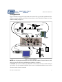
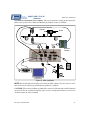
Figure 1 illustrates the physical components associated with a typical VA61 installation. Information on connector pinouts and electrical characteristics can be found in this Chapter, or in Appendix A starting on page 23.
detector
Kicker
1
1
2
Breakout
Module
2
+24
VDC
Figure 1. VA61 Installation
NOTE: Not all of the physical interfaces are used by the VA61 software. They are, however, available to the user for interfacing with third party products, if required.
CAUTION: The enclosure includes air intake holes at the rear of the unit and a small exhaust fan
on the front. For the continued reliability of the system, it is important that these areas are not
obstructed when the unit is mounted.
Rev 00; 16 October 2007
7
VA6x User’s Reference
405-00022-00
5. INSTALLATION
Pre-Installation Checks
1. Read the handling and operating precautions in Section 2.
2. Check that all essential components are present:
a. The VA61 unit
b. Display, keyboard and mouse
c. Camera(s) and associated cable(s)
d. C-Mount Lens for each camera
e. 24VDC power supply with 3.3 A output
f. Light Source, cable and power supply if necessary
g. Sensor trigger and cable (if required)
h. I/O breakout hardware
Interface Specifications
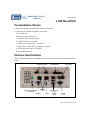
Before attempting installation, familiarize yourself with the various hardware interfaces detailed
below.
Industrial I/O
Camera Control
1
1
DC Power
2
2
Camera
Mouse & Keyboard
Network Port
Ports
PS/2 ports
and
Display
Audio
2 USB
Ports
Serial
Port
Figure 2. VA61 Rear Panel
8
Rev 00; 16 October 2007
405-00022-00
VA6x User’s Reference
Camera Connections
The standard camera that ships with the product has a resolution of 640x480 pixels, but this is
expandable up to 1600x1200. Different size cameras are available to suit application space
constraints.
DALSA offers cameras for use with our vision systems, some of which are referenced below. See
also directory: D:\PDF Manuals for available camera manuals.
NOTE
When you select the camera from DALSA, it will be tested with the cables and
Vision Appliance that are being shipped to you. Furthermore, the VA61will
have the appropriate configuration file loaded, making for a smooth out-of-thebox experience.
The camera interface supports:
• 2 camera inputs, supporting progressive scan digital GigE (Gigabit Ethernet) cameras with
standard or double-speed capabilities. Sherlock supports 2 asynchronous cameras. iNspect
and iLabel solutions support synchronous cameras; multiple cameras in a single Solution must
be synchronous. iNspect and iLabel do not support color cameras.
Recommended Camera List
The following cameras are offered by DALSA. Consult DALSA for alternate choices if required.
Model
Genie* M640
Genie M1024
Genie M1400
Genie M1600
Genie C640
Genie C1024
Genie C1400
Genie C1600
Type
monochrome
monochrome
monochrome
monochrome
color
color
color
color
Resolution
640x480
1024x768
1360x1024
1600x1200
640x480
1024x768
1360x1024
1600x1200
Full frame speed
64 fps
20 fps
15 fps
12 fps
64 fps
20 fps
15 fps
12 fps
* Standard camera that ships with the VA61.
Sherlock uses a separate configuration file, usually found in the \IFC\Config directory.
Camera Settings
NOTE
Cameras ordered with the VA61 are configured with two different IP Addresses
that match the two different GigE Port addresses on the VA61. The cameras cannot be swapped between the two camera ports.
Rev 00; 16 October 2007
9
VA6x User’s Reference
405-00022-00
In the factory default setting, VA61 Camera Port 1 is set to IP Address 10.1.64.5, and VA61 Camera Port 2 is set to IP Address 10.1.128.7. The VA-Genie Camera Setup program assigns compatible addresses to the two cameras. Once addresses are assigned, the cameras cannot be swapped
between the two camera ports.
Genie cameras purchased through a different distribution channel are usually set to dynamic addressing by default. This is usable in a distributed network situation, but not when cameras are
directly connected to the VA61 camera ports. The VA61 is not a DHCP server. Connect the cameras and run the VA-Genie Camera Setup program, to assign fixed addresses to the cameras.
The camera parameters are programmable through the GigE interface. DALSA IPD provides the
Sherlock camera I/O instructions, Sapera CamExpert utility, and iNspect/iLabel Sensor Setup
panel, for programming camera settings.
GigE Camera Video Data Cable
The GigE cameras are compatible with standard RJ45 ethernet connectors and cables. The Genie
cameras automatically sense or detect the transmit and send signals. This means you can use either a regular network cable or a crossover cable. DALSA offers a crossover cable with a locking
connector that attachs to the camera. This cable is also compatible with the standard RJ45 or
Ethernet connectors.
Part Number
A-CAB-GE-00
A-CAB-GE-01
A-CAB-GE-02
Cable Length
3 meters
5 meters
10 meters
Camera Control & Power Cable
The VA61 provides two standard DB15 or 15-pin D-Sub connectors for Camera I/O signals to
control trigger and receive strobe. 12 Volt power is also available on this connector.
• The camera can be triggered through the VA61 I/O. The external trigger would be input at the
25-pin Industrial I/O connector, and output to the cameras through the DB15 connectors, as
Camera IN2, illustrated in Figure 1 on page 7.
• The camera may have a Strobe output, that can be connected to the VA61 through the DB15
connectors, as Camera OUT2, and output to external lighting control equipment through the
25-pin Industrial I/O connector.
NOTE
10
iNspect, iLabel, and Sherlock assume IN2 is the camera trigger input, and
OUT2 is the camera strobe output. If you yuse CamExpert to create a camera
configuration file, make sure you use In2 for trigger, and Out2 for strobe.
Rev 00; 16 October 2007
405-00022-00
VA6x User’s Reference
Cable Pin-Out
Camera 12-Pin Hirose
1
2
3
4
5
6
7
8
9, 10
11
12
Description
Power Ground
+12 Volt Power
OUT 1 –
OUT 1 +
IN 1 –
IN 1 +
Out 2+ / Strobe
Out 2 –
No Connection
IN 2 + / Trigger
IN 2 –
Direction
Camera Output
Camera Input
Camera Output
Camera Input
VA61 15-Pin DB15
10
15
7 (no connnection on VA61)
13 (no connnection on VA61)
8 (no connnection on VA61)
14 (no connnection on VA61)
12
6
1,2,3,5,11
9
4
see below
12 pins
15 pins
Figure 3. Control and Power Cable
Part Number
A-CAB-GTP-00
A-CAB-GTP-01
A-CAB-GTP-02
Cable Length
3 meters
5 meters
10 meters
Another possible configuration would be:
• The camera is triggered directly from the part sensor, bypassing the VA61.
• The camera’s strobe output is connected directly to the lighting equipment, bypassing the
VA61.
For this case, DALSA offers an optional DCI-100 DALSA Camera Interface module for connecting the camera signals to terminal block connectors. The same Control and Power cable is
used to connect the Cameras to the DCI-100. The Camera Connectors on the VA61 would not be
used for the strobe and trigger signals when the DCI-100 is in use.
Rev 00; 16 October 2007
11
VA6x User’s Reference
405-00022-00
Network Connection
If your system is to be connected to a LAN (Local Area Network), connect a network cable to the
RJ45 Ethernet jack located over the 2 USB ports. The VA61 supports GigE (1,000BaseT) Fast
Ethernet (100BaseT) and Twisted Pair Ethernet (10BaseT). If you plan to use Fast Ethernet or
GigE, use a Category 5 (UTP5) cable. The default network port is the connector above the USB
ports. This network port is configured for Dynamic Addressing or DHCP. (The two camera ports
are configured for Static Addresses 192.168.0.100 and 192.168.1.100.)
Serial Port Connection
The VA61 has one RS-232/485 compliant serial port. The serial port is typically used for passing
results to a third party device, such as a PLC or other peripherials. The serial port is used to communicate with the optional DCI-100 DALSA Camera Interface module.
12
Rev 00; 16 October 2007
405-00022-00
VA6x User’s Reference
Industrial I/O Connections
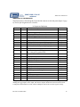
The VA61 interfaces I/O through the 25-pin D-Sub connector on the back panel (Figure 2, page
8). The I/O pin designations are as follows:
I/O Connector Definitions
Pin #
1
2
3
4
5
6
7
8
9
10
11
Direction
–
In
In
In
In
–
Out
Out
Out
Out
In
12
13 & 14
15
16
17
18
19
20
21
22
23
24
25
Out
–
In
In
In
In
–
Out
Out
Out
Out
Out
–
Definition in iNspect and iLabel
Ground
GPI0 or Trigger 1 input, from a part sensor
GPI2 Solution ID 1
GPI4 or Trigger 2 input, from a part sensor
GPI6 Solution ID 3
Ground
GPO0 or Strobe 1 output, to lighting equipment
GPO2 Decision Output 1
GPO4 or Strobe 2 output, to lighting equipment
GPO6
User Power input on PNP option
not connected on standard NPN
Fused +12V at 0.75A
Ground
GPI1 Change Solution input
GPI3 Solution ID 0
GPI5 Solution ID 2
GPI7 Solution ID 4
Ground
GPO1 Decision Output 0
GOP3 Inspection Running Status
GPO5
GPO7
Fused +5 V at .75 A
Ground
Sherlock
In Channel 0
In Channel 2
In Channel 4
In Channel 6
Out Channel 0
Out Channel 2
Out Channel 4
Out Channel 6
In Channel 1
In Channel 3
In Channel 5
In Channel 7
Out Channel 1
Out Channel 3
Out Channel 5
Out Channel 7
The application software (iNspect and iLabel) overrides I/O settings in the Camera Configuration File,
defining the trigger inputs, strobe output, and decision outputs. Sherlock uses the VA-Genie Camera
Configuration file definitions for I/O, and the CamExpert Camera file for Genie register settings.
Rev 00; 16 October 2007
13
VA6x User’s Reference
405-00022-00
Input Electrical Specifications
All VA61 inputs are single-ended, with the following specification:
Signal state
Low (Inactive)
High (Active)
Turn ON current
Min.
0V
2.4 V
1 mA
Max
0.8 V
30 V
Output Electrical Specifications
All VA61 outputs are single-ended, open collector, current sinking (NPN), with the following
specification:
Max
30 V
500 mA
25 V
Parameter
Output Voltage
Output Sink Current
Short Circuit Protection
NOTE
The NPN outputs are Open Collector. A pull-up resistor is needed to test the outputs.
VA61
non-isolated
sinking NPN output
External
Power
+7V–+35V
– +
User’s
active-low
sourcing input
V+
VA61
non-isolated
sinking NPN output
Out
External
Power
+7V–+35V
– +
Out
IN
GND
V+
R
GND
GND
User’s
active-low
sourcing input
IN
GND
Figure 4. Typical Output Wiring Diagram
Example Load Resistance (based on 10 mA load)
Voltage Source
24 V
30 V
14
Load R
4.8 K ohms
6 K ohms
Rev 00; 16 October 2007
405-00022-00
VA6x User’s Reference
I/O Breakout Options
The Industrial I/O connector is a standard 25-pin D-Sub connector. You may create your own
cable for making your connections. There is an optional VA61 breakout module with terminal
connectors and LED indicators, available from DALSA IPD.
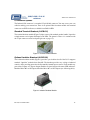
Standard Terminal Breakout (A-IOB-011)
The terminal breakout module (Figure 5) ships as part of the standard product bundle. It provides
a simple means to wire inputs and outputs to the VA61. The pinout is a direct 1–1 correlation with
the 25-pin connector on the back panel (pin-out on page 13).
Figure 5. Terminal Breakout Module
Optional Isolation Breakout (A-IOB-100)
The isolation breakout module (Figure 6) provides opto-isolation for all of the I/O. It supports
standard “Openline” modules from Grayhill. The breakout provides easy wiring to industrial
controls, while providing protection from potentially harmful power sources. Each module supports either 2 inputs or 2 outputs. Output modules are fused and provide status LED indicators.
Modules M0 to M3 are DC Inputs, Modules M4 to M7 are DC Outputs (see following table).
Figure 6. Isolation Breakout Module
Rev 00; 16 October 2007
15
VA6x User’s Reference
405-00022-00
Terminal Block Definitions for Opto-Isolation Breakout
Pin #
1
2
3
4
5
6
7
8
Function
IN0
GND
IN1
GND
IN2
GND
IN3
GND
Pin #
9
10
11
12
13
14
15
16
Function
IN4
GND
IN5
GND
IN6
GND
IN7
GND
Pin #
17
18
19
20
21
22
23
24
Function
OUT0+
OUT0–
OUT1+
OUT1–
OUT2+
OUT2–
OUT3+
OUT3–
Pin #
25
26
27
28
29
30
31
32
Function
OUT4+
OUT4–
OUT5+
OUT5–
OUT6+
OUT6–
OUT7+
OUT7–
Solution Switching Using I/O
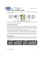
iNspect and iLabel Solutions can be switched through the I/O Connector or the Breakout board,
for line changeovers. You supply a 5-bit “Solution ID” number, 00 through 31, and a “load” signal, using 5 switches and a button. The necessary circuit is illustrated below, and the I/O Connector pin numbers are given.
Solution ID bit 0 pin 16
V+ pin 24
Solution ID bit 1 pin 3
Solution ID bit 2 pin 17
Solution ID bit 3 pin 5
Solution ID bit 4 pin 18
Change Solution input pin 15
Figure 7. Solution ID Switching Circuit
If there is no ID switch circuit attached, the application opens with Solution 00 running. If an ID
switch circuit is attached, the application starts/opens running the Solution ID indicated by the
switch.
NOTE
Do Not change the running Solution when in the History Recall panel, or when
any dialog boxes or message windows are open, such as image save, file or directory browse, Reject Restart Count, alarm messages.
If there is no ID switch attached, the Solution ID inputs 0–4 may be used as General Purpose inputs GPI3–GPI7 in Conditional Outputs and Equation Assignments in iLabel and iNspect Solutions.
16
Rev 00; 16 October 2007
405-00022-00
VA6x User’s Reference
Status LEDs and RESET Switch
The Vision Appliance provides 7 LEDs on the front panel, as visual health and status indicators
(shown in Figure 8).
LED0
Application
Amber
Red
Reject
LED3
LED1
Camera
Amber
Yellow
Recycle
LED4
LED2
Switch Solution Amber
Green
Pass
LED5
Reset Switch
Blue – Power
Figure 8. Front Panel Status LEDs and Reset Switch
The Reset button, when depressed, will initiate a system reset/reboot. The button is recessed in
the front panel to prevent accidental contact.
iNspect & iLabel function
As the iNspect or iLabel application opens, two of the LEDs start flashing. These represent “application” and “camera” health. The application “heartbeat” has a 2 second cycle, at 50% duty.
The camera “heartbeat” rate is dependent upon the type of camera and external event time or line
speed, and can be rapidly flashing, or may seem to be constantly on.
The other LED indicators represent “switch solution command” and inspection results (Pass/Recycle/Reject). In the iNspect and iLabel applications, the inspection results are updated with every inspection and visually indicate the state of the outputs on the I/O connector. The inspection
results LEDs are latched after a decision, and stay latched until the next decision is available.
Sherlock function
In Sherlock, all 6 LEDs are under your inspection program control. There are no predefined functions to the LEDs in Sherlock. The LEDs are available in Sherlock as Digital I/O output channels
8 through 13.
LED
LED0 amber
LED1 amber
LED2 amber
Sherlock Digital Output
Channel 8
Channel 9
Channel 10
Rev 00; 16 October 2007
LED
LED3 red
LED4 yellow
LED5 green
Sherlock Digital Output
Channel 11
Channel 12
Channel 13
17
VA6x User’s Reference
405-00022-00
Mounting Options
VA61 Chassis
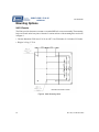
The VA61 provides the means to mount to a standard DIN rail or custom assembly. The mounting
holes are located on the base plate of the unit. Location and size of the mounting holes are shown
in Figure 9.
• Cabinet dimensions: W 20 cm x L 21.56 cm x H 7.5 cm; W 8 inches x L 8.6 inches x H 3 inches.
• Weight: 2.62 kg; 5.75 lb.
Dimensions are shown in inches.
Figure 9. VA61 Mounting Holes
18
Rev 00; 16 October 2007
405-00022-00
VA6x User’s Reference
Cameras
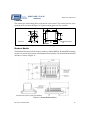
The cameras provide mounting holes on the bottom of the camera. The location and size of the
mounting holes are shown in Figure 10. Tripod mounting plates are also available.
13
50
44
Unit: mm
26
29
60
67
M3x0.5 4 Deep
8x
Figure 10. Genie Camera Mounting Holes
Breakout Module
The Breakout Boards provide the means to mount to a standard DIN rail. Standard DIN mounting
brackets are located on the bottom of the Breakout Board assembly. The Isolated Breakout Board
Assembly is shown in Figure 11.
Dimensions are shown in inches (and millimeters)
Figure 11. Isolated Breakout Board
Rev 00; 16 October 2007
19
VA6x User’s Reference
405-00022-00
Installation
1. Mount the Camera(s) and VA61 in a location free from excessive shock, moisture, and
vibration. The VA61 can be used with a standard DIN rail mount. Mounting holes are located on the base plate. See Figure 9 on page 18.
2. Connect a standard VGA Monitor to the Display connector.
3. Connect a mouse and keyboard, using either the PS/2 or USB connectors.
4. Thread the lens onto each camera lens mount.
5. Attach camera cables to each camera and connect them to the camera ports on the VA61. See
“Interface Specifications” and Figure 2, on page 8. If you ordered 2 cameras with the
VA61, make sure you match the camera and port correctly. The IP Addresses are configured for one port or the other and are not interchangable.
6. Connect the sensor trigger inputs to the I/O Connector (see pin-out, page 13) or the breakout
module.
7. Mount the light source. Connect the strobe controller (if required) to the strobe output of the
I/O Connector (see pinout, page 13) or the breakout module.
8. Wire the required outputs from the I/O to the PLC or pass/reject mechanisms (see pinout,
page 13).
9. Connect network as required (see “Network Connection” on page 12).
10. Connect Serial connections as required (see “Serial Port Connection” on page 12).
Before powering on the unit, take a couple of minutes to verify your hardware installation:
11. Verify all cable connections
12. Verify all electrical connections
13. Verify all components are securely mounted.
Complete the installation by applying power to the unit. The VA61 is powered from an external
supply (option A-PWR-NSII) that connects to the 3-pin D-Sub connector. The power requirements are:
• +24 Volts at +/– 3 Amperes
When the VA61 has booted, the Genie cameras take a minute to acquire their network connection
to the VA61. There is a camera icon in the system tray (near the time). Message balloons may
appear saying devices are connected or disconnected. Hover the cursor over this camera icon to
see status on the number of cameras successfully configured and available. Run the VA-Genie
camera setup utility to verify the cameras are connected correctly.
20
Rev 00; 16 October 2007
405-00022-00
VA6x User’s Reference
The hardware installation is now complete, and you can proceed to setting up the inspection.
Refer to the separate User’s Reference Manuals for iNspect, iLabel, or Sherlock.
detector
Kicker
Breakout
Module
+24
VDC
Figure 12. VA61 Installation
NOTE: Not all of the physical interfaces are used by the VA61 software. They are, however, available to the user for interfacing with third party products, if required.
CAUTION: The enclosure includes air intake holes at the rear of the unit and a small exhaust fan
on the front. For the continued reliability of the system, it is important that these areas are not
obstructed when the unit is mounted.
Rev 00; 16 October 2007
21
VA6x User’s Reference
405-00022-00
Camera Configuration
The Appliance is configured for the camera ordered with the unit, before shipping from DALSA.
The “IPD Camera and Language Selector” allows you to change the camera for the iNspect and
iLabel applications. If a saved Solution is not compatible with the selected camera, it will not
load or run. Use the Start button (or desktop icon if available) to open the camera selector. The
“IPD Camera and Language Selector” does not configure the camera for the Sherlock application. Use the Sherlock Options Menu –> Acquisition to select the camera. Refer to the Sherlock
Help or User’s Manual. The Sapera Acquisition Wizard identifies all available Sapera supported
hardware.
The iNspect and iLabel applications use a configuration file “NSPtest.txt” in the D:\iNspect directory. This file is copied from the directory \iNspect\Camera Files. This file defines the image
size and camera type, required to interface a particular camera. You can change settings in the
iNspect or iLabel application. The camera type and settings are saved in the Solution file. These
values are sent to the camera when the saved Solution is loaded.
The Sherlock software uses the values stored in the camera, or in a camera file. The SaperaLTDrv.ini file tells Sherlock how many Genie cameras are connected, and points to the CamExpert camera files. You can change settings using the Sapera CamExpert utility, or the Sherlock
instructions to set Gain and Exposure (shutter time).
Troubleshooting
1. You have powered the VA61 and launched iNspect or iLabel, but you do not see an image on
the display.
a. Verify the acquisition heartbeat is flashing. If it is not, a connection problem is likely.
Verify the cables again.
b. Verify that the lens aperture is not closed.
c. Verify that the inspection area (meaning the area that the camera is viewing) is correctly
illuminated.
d. Verify that all cameras are successfully configured and available, by hovering over the
camera icon in the System tray (by the time display in the lower right corner).
e. Verify that the camera and configuration file match. The iNspect/iLabel configuration
file is found at: D:\inspect\nsptest.txt. The VA61 was configured before shipping from
DALSA, to match the cameras ordered with the VA61. If the file does not match your
camera, contact your DALSA local representitive, or DALSA IPD headquarters, for help.
22
Rev 00; 16 October 2007
405-00022-00
VA6x User’s Reference
APPENDIX A
CONNECTORS AND PINOUTS
This section provides the connector pinout information for each of the VA4x external interfaces.
Camera Control Connectors
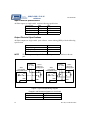
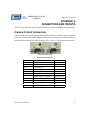
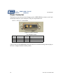
Camera image data is carried through RJ45 Ethernet connectors. Camera control signals and
power are available on two DB15 connectors. The location and pinout for the D-Sub connectors
are shown below. Each D-Sub cable can supply up to 0.5 A at +12 Volts from chassis power.
Pin 1
Figure 13. Video Ports
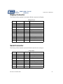
Camera Control Pin-Out
Pin number
1, 2, 3
4
5, 10
6
7
8
9
12
13
14
15
Rev 00; 16 October 2007
Description
Not Connected
Camera Input 2 –
Power Ground
Camera Output 2 –
Camera Output 1 –
Camera Input 1 –
Camera Input 2 + (trigger)
Camera Output 2 + (strobe)
Camera Output 1 +
Camera Input 1 +
+12 Volts (0.5A)
Direction
Out of VA61
In to VA61
no connection
no connection
Out of VA61
In to VA61
no connection
no connection
23
VA6x User’s Reference
405-00022-00
Power Connector
The VA61 is powered from an external supply (option A-PWR-NSII) that connects to the 3-pin
male D-Sub connector on the back panel. The power requirements are:
+24 V +/–10% @ 2.5 A maximum.
Pin 1
Figure 14. Power Connector
I/O Connector Pinout
Pin
1
2
3
Name
GND
+24V
NC
Direction
–
Input
–
Description
Ground
DC Power
not connected
A power cable (A-CAB-NSII-PWR), with open leads on one end and a mating connector plug on
the other, is shipped standard with the product.
24
Rev 00; 16 October 2007
405-00022-00
VA6x User’s Reference
I/O Connector
The Industrial I/O is available through the female 25-pin D-Sub connector.
Pin 1
Figure 15. I/O Connector
I/O Connector Definitions
Pin #
1
2
3
4
5
6
7
8
9
10
11
12
13 & 14
15
16
17
18
19
20
21
22
23
24
25
Direction
–
In
In
In
In
–
Out
Out
Out
Out
In
Out
–
In
In
In
In
–
Out
Out
Out
Out
Out
–
Definition in iNspect and iLabel
Ground
GPI0 Trigger 1 input
GPI2 Solution ID 1
GPI4 Trigger 2 input or Solution ID 5
GPI6 Solution ID 3
Ground
GPO0 Strobe 1 output
GPO2 Decision Output 1
GPO4 Strobe 2 output
GPO6
Not connected on standard NPN. User Power input on PNP option.
Fused +12V at 0.75A
Ground
GPI1 Change Solution Input
GPI3 Solution ID 0
GPI5 Solution ID 2
GPI7 Solution ID 4
Ground
GPO1 Decision Output 0
GOP3 Inspection Running Status
GPO5
GPO7
Fused +5 V at .75 A
Ground
The application software (iNspect and iLabel) overrides I/O settings in the Camera Configuration
File, defining the trigger inputs, strobe output, and decision outputs.
Rev 00; 16 October 2007
25
VA6x User’s Reference
405-00022-00
Ethernet and USB Connectors
The Ethernet RJ-45 connector is an 8-pin male connector. The two USB 1.1 connectors reside
below the Ethernet connector. They are identical, rectangular type-A, 4-pin sockets.
Ethernet
USB
USB
Figure 16. Ethernet and USB Connectors
Ethernet Pinout
Pin
1
2
3
4–5
6
7–8
Name
TD+
TD–
RD+
NC
RD–
NC
Direction
Out
Out
In
–
In
–
Pin
1
2
3
4
Name
VCC
DATA–
DATA+
GND
Direction
Out
I/O
I/O
–
Description
Transmit Data+
Transmit Data–
Receive Data+
not connected
Receive Data–
not connected
USB Pinout
26
Description
Power, +5 V (1 A max)
Data–
Data+
Ground
Rev 00; 16 October 2007
405-00022-00
VA6x User’s Reference
Display Connector
The VA4x provides standard 15-pin female D-Sub connection for Display.
Display Pinout
Pin
1
2
3
4
5–8
9
10
11
12
13
14
15
Name
RED
GREEN
BLUE
NC
GND
+5V
GND
NC
SDA
HS
VS
SCL
Direction
Out
Out
Out
–
–
Out
–
–
I/O
Out
Out
I/O
Description
Red
Green
Blue
not connected
Ground
+5 V
Ground
not connected
Serial data
Horizontal Sync
Vertical Sync
Serial data clock
Serial Connector
The VA4x provides standard 9-pin male D-Sub connection for serial port.
Serial Pinout
Pin
1
2
3
4
5
6
7
8
9
Name
DCD
RXD
TXD
DTR
GND
DTS
RTS
CTS
RI
Rev 00; 16 October 2007
Direction
In
In
Out
In
–
Out
Out
In
In
Description
Data Carrier Detect
Receive Data
Transmit Data
Data Terminal Ready
Ground
Data Set Ready
Request to Send
Clear to send
Ring Indicator
27
VA6x User’s Reference
405-00022-00
APPENDIX B
STAGING AND PRESENTATION
To measure or inspect a part or object, it must be positioned so the camera can see it. Positioning,
sometimes called staging, presentation, or fixturing, puts the part in the camera’s field of view
(FOV), signals the Vision Appliance that a part is available, and helps hold the part steady while
an image is being taken.
The camera is responsible for generating an electronic image of the part for processing by the
Vision Appliance. The camera and lighting help with the part positioning because they are used
to “freeze” or “stop” the motion of a moving part.
An Example
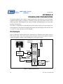
Figure 17 illustrates a bottle inspection line, seen from above. The bottles move along a conveyer
belt, past the camera. The conveyer belt positions the bottle in front of the camera, so that the
camera can capture an image of the threading on top of the bottle’s neck.
Bottle Line
Movement
Vision
Appliance
L
i
g
h
t
Camera
Part–in–Place Sensor
Reject
Defective
Bottles
Good Bottles
Figure 17. Bottle Inspection Line
28
Rev 00; 16 October 2007
405-00022-00
VA6x User’s Reference
A diffuse, uniform light behind the threads gives a sharp, high-contrast image of the threads. The
Vision Appliance inspects this image and signals a rejection “kicker” to move defective product
off the production line.
Part-in-Place Sensor
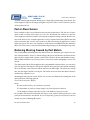
In this example we have two problems because the parts (bottles) move. We first have to know
when a bottle is in front of the camera so it can “see” the threads. One solution is to have the
Vision Appliance look for the threads, and only take an inspection image when the thread is centered in the field of view. A simpler approach is to have a separate Part-in-Place (PiP) sensor that
detects when the bottle is in the correct position. A PiP sensor allows the Appliance to work at
higher part speeds. We have used inexpensive, PiP sensors from HTM Electronics Industries
(http://www.htm–sensors.com) and from Banner Engineering (www.bannerengineering.com).
Reducing Blurring Caused by Part Motion
The second problem is blurring caused by motion of the part. When the part is in place, the motion of the part must be “frozen” so that the image of the part is not blurred by the motion. Sometimes the part is stopped while a picture is taken. This is ideal for the best measurement accuracy.
With continuous motion, as on a conveyer belt, we rely on the camera and lighting to “freeze” the
motion.
The camera used with the Vision Appliance has a programmable exposure time so you can set the
part viewing time. Selecting the viewing time depends on the part speed, the amount of blurring
due to motion that can be tolerated, and the amount of available light. The shorter the viewing
time, the more light is needed to see the part. The camera also has an electronic shutter, but this is
automatically adjusted for you.
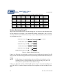
Assuming that only one part is in the field of view at a time, an estimate of the viewing time can be
derived from the following equation:
View Time in seconds = B/(P*I)
where:
B is the amount of blur you can tolerate (in pixels),
P is the number of pixels per image (image size) in the direction of motion,
I is the number of images taken per second, or the number of parts per second.
For example, if the motion is horizontal with respect to the camera, and the picture size is 640
pixels per horizontal line, then P=640. If you are inspecting 5 parts per second (I=5), and can
tolerate one pixel of blurring (B=1) then:
Rev 00; 16 October 2007
29
VA6x User’s Reference
405-00022-00
View Time = 1/(640*5) = 315 microseconds
This is within the camera exposure range (and shutter speeds) but will require good illumination,
perhaps by an LED strobe, because the exposure time is brief.
In iNspect/iLabel, you adjust the camera’s exposure time using the Exposure Control slider on
the Vision Appliance’s Sensor Setup screen. In Sherlock you adjust the exposure time by programming the shutter speed, using the IO:Camera:Set Shutter instruction, or using CamExpert to
create a camera file. The maximum shutter time (exposure time) must be less than the frame time.
As the frame rate increases, the maximum shutter time decreases.
In practice, you will adjust the exposure to balance good image contrast against visible blur due
to part motion.
Blurring of the image caused by the motion of the part (motion blur), even when not visible to the
human eye looking at the camera image, will reduce the accuracy of measurements. Ideally, measurements should be performed on a part that is not moving, so there is no motion blur and so that
a longer exposure (and smaller lens aperture) can be used.
Progressive Scan Cameras
In addition to programmable exposure, the camera is non-interlaced (usually called progressive
scan). If you intend to use a different camera with your Vision Appliance, call ipd for supported
cameras. Make sure that it is progressive scan, has an electronic shutter, and is compatible with
the control signals, power, and cabling.
Strobe Lighting
A strobe light provides a brief, high-intensity pulse of light that can help reduce motion blur and
still provide adequate illumination to the part being inspected. Traditional xenon strobe lights are
bright and can be very short in duration, less than 100 microseconds, to “freeze” the part motion.
Xenon strobes have substantial variability in intensity. This can create variations in the image
quality, which could be mistaken for variation in the part quality. Xenon strobe lights are used
only when there is no easier way to get short, high-intensity light. LEDs (Light Emitting Diodes)
can also be used as a strobe, and over-driven to give a short, bright pulse of light.
Even with a strobe illumination source, you need a camera with an electronic shutter and exposure time to prevent ambient light from contaminating the image. The Vision Appliance has a
dedicated I/O line for firing a fast strobe, because this must be done at a certain time after the
exposure has been triggered. Longer duration light, for example LEDs again, can be controlled
30
Rev 00; 16 October 2007
405-00022-00
VA6x User’s Reference
using a standard I/O line, and are turned on before the camera’s exposure is triggered and turned
off after the exposure is done. This minimizes the intensity variation on different exposures.
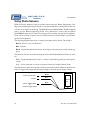
Using Contact Closures
Mechanical contacts, such as switches or relays, typically exhibit “bounce.” The moving contact
makes the electrical circuit by touching a fixed contact, but then bounces off this fixed contact.
The result is a series of rapid closing and openings of the contact until the moving contact stops
bouncing. Bouncing typically continues for less than 10 milliseconds, but the duration depends
on mechanical factors of the switch. This oscilloscope trace shows about 5 ms (milliseconds) of
bounce when a switch is closed:
Figure 18. Example of switch “bounce” during a contact closure
From Switch Bounce and Other Dirty Secrets, Maxim Integrated Products, Inc., Sept. 2000
The problem is, the Vision Appliance “sees” the bouncing as multiple, rapid input signals. For
example, if your “part in place” sensor is a mechanical switch (say, a photocell running a relay),
the contact bounce will make it appear as if many parts were being presented to the Vision Appliance in a few milliseconds.
Here are three ways to deal with bounce. (1) Use a signal that does not bounce; for example, from
a photoelectric sensor. (2) Use the built-in de-bouncing circuits. The de-bounce circuit delays the
VA4x from responding to the input for some number of microseconds (us) to allow time for the
contact to settle. The de-bounce time can be programmed through the camera configuration file.
(3) Externally de-bounce the switch closure using commercial de-bounce chips (for example, the
Maxim MAX6816), or a low-pass filter and Schmitt trigger.
Both the Vision Appliance and external de-bounce circuits delay the input signal by the debounce period. This delay is rarely long enough to be a problem, but might have to be considered
in very high-speed applications where any delay might mean the parts being inspected move partially out of the field of view.
Rev 00; 16 October 2007
31
VA6x User’s Reference
405-00022-00
Using Photo-Sensors
HTM Electronics Industries (http://www.htm–sensors.com) and Banner Engineering Corp.
(http://www.bannerengineering.com) and several other manufacturers make photoelectric sensors that do not require de-bouncing. The HTM Electronics MP-D0380D-CX9Q4UE infrared
sensor, and the Banner Engineering R55F series photoelectric sensors and the SM312
LVAGMHSQD photoelectric sensor have been used successfully with the Vision Appliance.
These sensors are rated to operate on 10 to 30 VDC; but do not exceed 24 VDC or you will damage the Vision Appliance.
The following diagram shows how to connect these photoelectric sensors. The wiring is:
Brown - Power (+16 to +24 Volts DC)
Blue - Ground
Black - Signal from photoelectric sensor. Goes high (to about the power voltage) when triggered.
The other two wires are not needed for using the sensor with the Breakout Board. These two wires
are:
White - Signal from photoelectric sensor – connects a small load to ground (see sensor specification)
Gray - Can be connected to a switch to ground; when closed, enables Remote Teach
The photoelectric sensor draws power from the brown and blue leads. When the photoelectric
sensor is triggered the output (black lead) goes high (to about the power supply voltage).
+ Power (16–24 VDC)
Ground
Sensor Trigger (GPI0)
or
Decision Trigger (GPI2)
Brown
Blue
Black
Sensor
Unit
Figure 19. Photosensor Connections
32
Rev 00; 16 October 2007
405-00022-00
VA6x User’s Reference
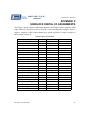
APPENDIX C
SHERLOCK DIGITAL I/O ASSIGNMENTS
The Trigger 1 input is assigned to GPI0 (input channel 0), and Trigger 2 input is assigned to GPI4
(input channel 4). The inputs are always available, even when assigned as a triggers. Strobe 1
output is assigned to GPO0 (output channel 0) by default, and Strobe 2 output is assigned to
GPO4 (output channel 4).
Default Digital I/O Definitions
Sherlock Digital I/O
output Channel 0 (Strobe 1)
output Channel 1
output Channel 2
output Channel 3
output Channel 4 (Strobe 2)
output Channel 5
output Channel 6
output Channel 7
output Channel 8
output Channel 9
output Channel 10
output Channel 11
output Channel 12
output Channel 13
input Channel 0 (Trigger 1)
input Channel 1
input Channel 2
input Channel 3
input Channel 4 (Trigger 2)
input Channel 5
input Channel 6
input Channel 7
Rev 00; 16 October 2007
Direction
out
out
out
out
out
out
out
out
out
out
out
out
out
out
in
in
in
in
in
in
in
in
Name
GPO0
GPO1
GPO2
GPO3
GPO4
GPO5
GPO6
GPO7
LED0 (amber)
LED1 (amber)
LED2 (amber)
LED3 (red)
LED4 (yellow)
LED5 (green)
GPI0
GPI1
GPI2
GPI3
GPI4
GPI5
GPI6
GPI7
I/O Connector Pin
7
20
8
21
9
22
10
23
–
–
–
–
–
–
2
15
3
16
4
17
5
18
33
VA6x User’s Reference
405-00022-00
APPENDIX D
NON-STANDARD OPTIONS
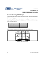
Current Sourcing PNP Output
Current Sourcing PNP output is a special order option for the VA61. The normal configuration is
NPN Current Sinking outputs.
Current Sourcing (PNP) outputs are driven high when active. The specifications are as follows.
Output Voltage is determined by the User supplied power 7–35 Volts on the User Power input
(pin 11 on the I/O connector).
Parameter
Output Voltage
Output Source Current
Over Current Protection
Max
UserPower (7–35 V)
350 mA
500 ma
Figure 20 illustrates driving an active-high sinking input with the PNP outputs.
External
VA61
Power
non-isolated
+7V–+35V
sourcing PNP output
– +
UserPower
User’s
active-high
sinking input
V+
Out
IN
GND
GND
Figure 20. PNP Sourcing Outputs
34
Rev 00; 16 October 2007