1
Installation Guide
NOVARA CP-3008 ControlPad
Overview
NOVARA CP-3008 ControlPad Specifications (Cont.)
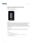
The Novara CP-3008 ControlPad (FG1302-08) (FIG. 1) with built-in Ethernet port
combines a controller with an easy to use 8-button keypad that mounts onto a
standard two gang US, UK, or EU back box. The ControlPads are configured using the
NOVARA DCS (Device Configuration Software) software application, available for
download from www.amx.com. Refer to the NOVARA 3000 Series ControlPads &
KeyPads Operation/Reference Guide (available at www.amx.com) for configuration
instructions. The CP-3008 ControlPad can be configured to control volume, input
selection and power for a wide range of A/V devices.
The ControlPad connects to AMX's Resource Management Suite® (RMS) which
enables web-based remote diagnostics and management through the built-in Ethernet
Port. The ControlPads are available in Black, White, and Brushed Aluminum finishes.
Operating
Environment:
• Storage temperature range: 14° - 140° F (-10° - 60° C)
• Operating temperature range: 32° - 104° F (0° - 40° C)
• Relative humidity: 5% to 85%, non-condensing
Included Accessories:
• Power Supply, 90-240VACIN, 12VOUT, 500MA
(24-5791-SA)
• Pre-printed labels (40-0087)
Other AMX Equipment: • CP-RMS, RMS Gateway Module (FG1310-01)
• CC-NIRC, NetLinx IR Emitter (FG10-000-11)
Certifications:
FCC Class B, CE, UL, CB Scheme
Mounting Specifications
CP-3008 8-button keypads mount onto standard 2 gang US, UK, or EU back boxes.
FIG. 2 displays the dimensions for the CP-3008 ControlPad.
FIG. 1 Novara CP-3008-BA ControlPad
Product Specifications
NOVARA CP-3008 ControlPad Specifications
Power Requirements:
• Min: 121mA@12 VDC
• Max: 320mA@12 VDC
• Using a non-PoE power supply operates on voltages
ranging from 9V to 16V continuously.
Button Layout:
• 8 red, green, and blue backlit buttons with
programmable feedback
• Pressable volume knob
• Volume indicator
Colors:
Rear Panel
Connectors:
• Aluminum: FG1302-08-A
• Black: FG1302-08-B
• White: FG1302-08-W
• Power - 1 2-pin Phoenix connector accepting 12VDC
power
• Serial - 2 3-pin Phoenix connectors for RS-232
connections.
Input voltage: VIH > +2.7 VDC, VIL < -2.7 VDC
Output voltage: VOH > +5.0 VDC @ 35 mA maximum,
VOL < -5.0 VDC @ 35 mA maximum
• IR - 2 2-pin Phoenix connectors for IR emitters.
Supports generating carriers up to 1.142 MHz. Output
only port.
Output voltage:
VOH = +3.3 VDC +/- 0.3 VDC @ 13 mA maximum
VOL = 0 VDC +/- 0.3 VDC @ 13 mA maximum
• I/O - 1 4-pin Phoenix connector for I/O connections.
Supports sensing contact closure.
Input voltage:
HIGH (no contact closure): VIH > 2.5 VDC
LOW (contact closure): VIL < 0.8 VDC
Output voltage:
VOH = +3.3 VDC +/- 0.3 VDC (internal 25k Ohm
pull-up resistor)
VOL = 0 VDC +/- 0.3 VDC (200 mA maximum sink
current)
• Relay - 1 4-pin Phoenix connector for relay connections
capable of switching 24 VDC @ 1A maximum or
28VAC @ 1A maximum
FIG. 2 CP-3008 dimensions
Wiring and Connections
Power
The CP-3008 features a 2-pin Phoenix connector accepting 12VDC power.
GND
ControlPad
FIG. 3 Power Supply wiring
Serial Connectors
The CP-3008 features two RS-232 connector ports so you can connect up to two
serial devices to the ControlPad. The serial connectors comply with EIA-232-F signal
levels.
RX
TX
TX
RX
GND
Up to 115200
Dimensions (HWD):
4 11/16" x 6" x 1 3/4" (including knob)
(11.9cm x 15.2 cm x 4.5 cm)
Weight:
0.863 lbs (0.392 kg)
GND
ControlPad
External Device
FIG. 4 Serial Connector wiring
IR Connectors
The CP-3008 features two IR connector ports so you can connect up to two
IR-controllable devices to the ControlPad. The IR/Serial connector wiring
specifications are listed in the following table:
IR Connector Wiring Specifications
IR connections
• LAN - 1 RJ-45 connector for LAN connectivity.
• Reset - 1 pinhole pushbutton for factory reset.
Supported Baud
Rates:
+12VDC
Power Supply
Signal
Function
1
GND (-)
Signal 1 (+)
Signal GND
IR data
2
GND (-)
Signal 2 (+)
Signal GND
IR data
FIG. 5 IR port
WARNING: Do NOT connect a power connector to either IR port. Doing so may
damage the ControlPad.
I/O Connectors
The CP-3008 features I/O connector so you can connect one input/output device to
the ControlPad. The PWR pin provides +12 VDC @ 200 mA and is designed as a
power output for the PCS Power Current Sensors, VSS2 Video Sync Sensors (or
equivalent). The GND connector is a common ground and is shared by all I/O ports.
A common ground is shared with I/O ports 1 - 2.
Key Cap - tilted so that the bottom
of the Cap is placed on the bottom
of the pushbutton first
At this point, do not allow the clips
on the sides of the Key Cap to engage
Clip
1
I/O Port Wiring Specifications
Signal
Clip
Function
+12V:
PWR
1:
Input/Output
2:
Input/Output
GND
Signal GND
Pushbutton on keypad
Press the top of the Key Cap
down to engage both clips at
once, securing the Key Cap
to the pushbutton
FIG. 6 I/O port
Relays
2
You cann connect up to two independent external relay devices to
the Relay connectors on the ControlPad. Connectors labeled A
are for Common and B are for output.
Once the clips are engaged,
the Key Cap is secured
to the pushbutton
3
FIG. 7 Relay port
LAN Port
FIG. 10 Placing a Button Label inside a Key Cap
The LAN RJ-45 port provides 10/100 Mbps communication via
Cat5/5e/6 network cable. The LAN port uses standard Cat5/5e/6
cables.
Note: Be careful to follow these procedures closely - the bottom of the Key Cap must
be installed on the pushbutton before the Key Cap clips engage, or there is a risk of
the button being misaligned.
Removing Key Caps
If a Key Cap needs to be removed, the user should lift it very carefully from one side
to prevent damage to the button, as indicated in FIG. 11:
FIG. 8 LAN port
Button Labelling
NOVARA ControlPads and KeyPads come with a set of clear plastic Key Caps,
which are designed to fit tightly over the pushbuttons, and allow you to place a label
on each button according to the requirements of your particular installation.
NOVARA ControlPads and KeyPads also come with a pre-printed acetate sheet with
a range of 50 (pre-cut) button label inserts. The button labels provided will
accommodate most installations, but it is also possible to print your own button labels
on acetate for custom button labelling.
WARNING: Attempting to remove the Key Caps while the faceplate is still installed
can damage the unit. Use care when removing the Key Caps. Always remove the
faceplate before removing the Key Caps. Mishandling the Key Caps can cause
permanent damage to the unit and voids warranty.
Clear Key Cap installed
on the Pushbutton
To remove the Key Cap, gently lift
up one side to remove the Cap
from the Pushbutton at an angle
Installing Acetate Button Labels and Key Caps - READ THIS FIRST!
1.
•
•
2.
Punch out the desired Button Label from the included acetate sheet.
If you have printed your own custom button labels on acetate, cut each button
label to fit inside the Key Caps.
Custom button labels must be cut to a 1.14cm (0.45") square to fit securely
inside the Key Caps.
The thickness of the acetate used must not exceed .004” (0.10 mm).
Place the Key Cap face-down, and insert the Button Label into the bottom of
the Key Cap (FIG. 9).
Acetate Button Label
(face down)
Clip
FIG. 11 Removing a Key Cap from the Pushbutton
Key Cap (face-down)
Clip
AMX recommends finalizing the ControlPad configuration prior to Key Cap and
button label installation to avoid unnecessary removal of Key Caps.
Re-Assembling the ControlPad
FIG. 9 Placing a Button Label inside a Key Cap
•
Avoid lifting the Key Cap
straight up from the Pushbutton
Orient the Button Label inside the Key Cap so that the two clips are located on
the left and right sides of the readable text on the Button Label, as indicated in
FIG. 9.
• Be sure to place the Button Label face-down inside the Key Cap (see FIG. 9),
otherwise the label will be seen in reverse once the Key Cap is installed.
3.
Install the Key Cap on the pushbutton (see FIG. 10).
Note: Verify that the vertical orientation of the Button Label is correct relative to the
keypad.
a. Gently press the bottom of the Key Cap (no clip) onto the pushbutton.
Do not allow the clips on either side to engage.
b. With the bottom of the Key Cap secured, gently press the top of the Key
Cap. This action will engage both clips simultaneously, and the Key Cap
will snap into place on the push button.
Follow these steps to re-assemble the keypad.
1.
With all button Key Caps in place, put the faceplate over the circuit board.
2.
Use the supplied #6 screws to secure the faceplate to the circuit board. There
are two screw holes on the top of the faceplate rim, and two on the bottom. Use
either the Torx screws or #4 Phillips-head screws to attach the faceplate. Use a
Torx driver with a T8 tip for the Torx screws; use a Phillips-head screwdriver for
the Phillips-head screws.
3.
Reattach the knob to the faceplate and screw it in as far as it can go.You
should be able to press the knob as a button for extra functionality.
4.
Tighten the knob in place using a .050" hex driver in the hole in the side of the
knob.
Refer to the NOVARA 3000-Series ControlPads & Keypads Operation/Reference
Guide (available at www.amx.com) for additional installation details and configuration
instructions.
For full warranty information, refer to the AMX Instruction Manual(s) associated with your Product(s).
2/12
©2012 AMX. All rights reserved. AMX and the AMX logo are registered trademarks of AMX.
AMX reserves the right to alter specifications without notice at any time.
3000 RESEARCH DRIVE, RICHARDSON, TX 75082 • 800.222.0193 • fax 469.624.7153 • technical support 800.932.6993 • www.amx.com
93-1302-02
REV: J