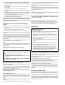
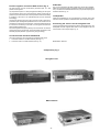
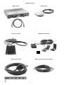
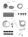
1
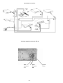
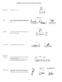
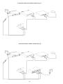
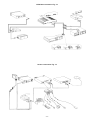
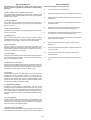
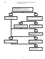
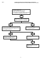
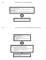
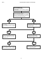
MULTIMEDIA SYSTEM
Berlin RCM 303 A
Installation instructions GB
3 D94 653 072
Navigation component
TravelPilot RG 05
7 612 001 110
GB
Positive connection Fig. 2
The navigation unit must be connected to permanent plus 12 V and
positive via the ignition.
Safety instructions
Lay the permanent plus 12 V wire (red) to the battery (do not lay the wiring
directly by the wire harnesses). Attach the fuse carrier to protect the
positive wire and connect it to the positive terminal on the battery (if
necessary, drill a hole through the splashboard and use wire bushings
accordingly).
Installation and connection regulations
While installing and mounting this equipment, you must
disconnect the negative terminal of the battery. Important:
You must also comply with all safety instructions given by the
auto manufacturer (alarm system, vehicle immobilizer, airbag)!
Use wire bushings on sharp-edged holes.
Connect the switching plus wire (black) with the fuse carrier at terminal
15 (switched to plus via the ignition) behind the fuse. In cars in which it
is not possible to connect the wire in the fuse box, use the enclosed fuse
carrier to connect the wire directly to terminal 15 at the ignition. Remove
the steering wheel panelling first.
In order to avoid any interference, lay all wiring far enough away
from the wire harnesses.
Negative connection Fig. 2
Before drilling holes for mounting the equipment or laying the
wiring, make sure that no existing wiring or auto parts (such as the
petrol tank, fuel line) will be damaged.
Equipment fuses:
Basic unit:
Screw the negative wire (brown) directly onto the chassis. Scratch the
contact point for the ground down to the bare metal and grease it with
antiseize graphite petroleum (important for good grounding).
5 A wire fuse
5 A miniature fuse
GPS receiver:
5 A wire fuse
Magnetic field sensor (electronic compass)
Notes on the operation of the system
In order to ensure the trouble-free operation of the navigation system, a
calibration must be performed after the equipment has been installed. A
special installation and calibration CD-ROM, including operating
instructions, is required. Software available for the Berlin RCM 303 A
operating panel from version 04.11.94 is capable of controlling the
navigation componentry. Older software must be replaced by the most
recent update, whereby an update for the tuner software is also required
(at least version 08.09.94).
Note: An error message list, a service checklist and diagnostic aids have
been included at the end of these installation instructions.
Componentry Fig. 1
The navigation componentry consists of a navigation computer with an
integrated CD-ROM drive (navigation unit), a NAVI interface, a GPS
receiver with an antenna, a precision resistor for the rear window
defogger, a magnetic field sensor, wheel sensors, a loudspeaker and
mounting material.
Mounting location for the navigation unit
Note: You must determine the optimum mounting location for
the magnetic field sensor in each vehicle individually. Before
permanently installing the magnetic field sensor, attach it
temporarily and then test the chosen location with the installation
and calibration CD-ROM to make sure everything operates
correctly.
The magnetic field sensor must be installed in the passenger room. It
determines the driving direction by measuring the horizontal earth
magnetic field component. Since the earth magnet field is relatively
small, you must ensure that there is no magnetic or electromagnetic
interference affecting the magnet field sensor at the chosen mounting
location.
Use the enclosed mounts to attach the magnet field sensor to a window
which cannot be opened or, especially where estate wagons or liftback
cars are concerned, mount it without fasteners underneath the inside roof
lining using double-sided sticky tape.
Note: If the magnetic field sensor is mounted in the direct vicinity
of an AM radio antenna integrated into the rear window, it may
cause occasional interference in the radio reception in the long
wave range.
Remove the transport block (two brass screws in the upper plate)
before beginning the installation work. Keep these screws in a safe
place in case the unit must be set in for servicing. After removing
the screws, insert the enclosed plugs into the holes in the upper
plate.
Testing the mounting location of the magnetic field
sensor
The navigation unit need not be installed at any particular position.
1. Test for permanent magnetic interference
When choosing the mounting location for the navigation unit, you must
make sure that the unit is installed lying in a horizontal position (you must
be able to read the writing on the flap).
Load the installation disk.
Make sure that there is enough room to insert the navigation CD into the
CD drive. Use the enclosed installation material in order to mount the
navigation unit.Positive connection Fig. 2
-1-
Two different tests are required.
Select „find compass location“, and then „compass ellipse“ and drive the
vehicle in a circle. A circle should appear on the display inside the
squares (ideally the circle should be in the centre). If this circle is partially
or entirely outside of the squares, then you must mount the magnetic field
sensor in a different place.
2. Testing for interference caused by other electrical equipment
Load the installation disk, select „find compass location“ and then
„compass error“.
Press „reset“, switch on the consumers (e.g. sliding sun roof, rear
window wiper).
The value indicated for „Loc. error“ must be less than 3.5.
Press reset each time you switch on a different piece of electrical
equipment.
of rust, dirt, grease and water. Clean the inside of the wheel rim
thoroughly (brake cleaning fluid, brake and clutch cleaner).
To ensure that the glue adheres properly, the rims must be at room
temperature.
After thoroughly cleaning and perhaps allowing the rims to warm up, glue
the magnetic strips onto the marked spots over the entire area parallel to
the outer edge of the rim, Fig. 4
Notes
After having tested each piece of electrical consumer individually,
check logical combinations as well. The sum of the values for the
consumers must not exceed a „Loc. error“ of 3.5.
Do not glue the magnetic strips directly onto the edge of the rim, as here
they can be damaged very easily.
If the value registered exceeds 3.5, then you must mount the
magnetic field sensor in a different location.
Do not piece the magnetic strip together and cut it only at the
marked points (maximum gap between the beginning and end
point, one field = 25 mm).
Note: Do not switch on the rear window defogger while testing for
interference from the electrical equipment. Any interference caused
by the rear window defogger is registered separately during
calibration and then compensated.
Mount the wheels and tighten the nuts. Align the wheel sensors in
keeping with the installation tolerances, Fig. 5, and screw them on.
Lay the sensor wires into the interior of the vehicle (use any existing
bushings or drill new holes) and lay them to the navigation unit.
Precision resistor for the rear window defogger
(shunt)
The precision resistor has 2 connection wires and 1 measuring wire:
GPS receiver
1. Connection to the ground contact of the rear window defogger
(length: 250 cm),
Mounting the antenna
2. Connection to the vehicle chassis (length: 75 cm),
3. Measuring wire to the navigation unit (length: 50 cm), Fig. 3
The mounting location of the precision resistor depends on the length of
the wiring.
Do not lengthen the connection wires for the ground contact and the
vehicle chassis. Do not attach the connection for the vehicle chassis to
the liftback in estate wagons or liftback cars. Select the mounting location
for the precision resistor so that any heat build-up will be eliminated
(chassis metal).
Important information:
- Mount the antenna on a metal roof only. It is not permissible to
mount the antenna on synthetic roofs or aluminium.
- When mounted on a roof (held only by a magnet), the antenna
must not be exposed to temperatures lying outside a range of -20°
C to +80° C.
- It is not permissible to mount the antenna on roofs covered with
leather or synthetic material.
Lay the measuring wire to the navigation unit and connect it to the
corresponding jack of the compact plug, Fig. 3
- Use protective sheathing to protect the antenna wire from being
pinched.
Note:
- The adhering surface of the antenna must be free of dirt, snow, ice,
etc.
No other electrical equipment (e.g. rear window wiper) may be connected
to the ground contact for the rear window defogger, except for the rear
window defogger.
- You must not lengthen, shorten or bend the antenna wire. Do not
remove the plug during the installation.
- If the antenna is painted with the same colour as the vehicle,
especially paints containing a high percentage of metal, this may
adversely affect the reception. There is no guarantee that the
antenna will operate properly after it has been painted.
Wheel sensors and magnetic strips Fig. 4
Safety instructions
Never drill holes in any stress-bearing parts.
Seen from the driving direction, the antenna is to be mounted on the righthand side in the rear of the vehicle (passenger’s side, in Great Britain,
driver’s side). On notchback vehicles, mount the antenna on the lid of the
boot using the corner clamps, Fig. 6.
Do not attach the sensor wiring to the brake lines or to any
moving parts.
On estate wagons and liftback cars, set the antenna on the roof with its
magnetic foot, Fig. 7.
The wheels must be tightened using the torque recommended
by the factory (approx. 100 Nm).
For a roof mount, remove the corner clamps, Fig. 8.
Never screw the wheel sensor clamp onto any stress-bearing
parts.
For estate wagons and liftback cars, lay the antenna wire along the rain
gutter downwards and into the interior of the vehicle, Fig. 9.
Mount the wheel sensors and the magnetic strips on the free-rolling
wheels, for four-wheel drive cars, on the rear wheels.
Any obstacles near the antenna, such as roof or bicycle carriers, may
adversely affect or even prevent satellite reception.
In order to mount both the wheel sensors and the magnetic strips, the
vehicle must be jacked up.
Lay the antenna wire into the interior of the vehicle and connect the BNC
plug on the antenna wire with the antenna jack on the GPS receiver.
Screw the wheel sensors onto the sensor mounts and look for a suitable
mounting location. The sensors must not swing mechanically and they
should be placed in a sheltered location.
It is advisable to remove the antenna from the roof when driving through
a carwash.
While mounting the wheel sensors, it is essential to comply with the
installation tolerances, Fig. 5
Mounting the GPS receiver
The location for the GPS receiver is dependent on the length of the
antenna wire (2.5 m) and the connection wire to the navigation unit (1.5
m).
Mounting the magnetic strips
After you have found a suitable location for the wheel sensors, you must
determine the position of the magnetic strips on the inside of the wheel
rims. Mark the location selected for the magnetic strip and remove the
wheel.
Before unscrewing the wheel nuts, mark the position of the wheel on the
wheel hub.
Because the magnetic strips are glued into position, the rim must be free
-2-
Cut the perforated strips into equal lengths and bend them to form corner
clamps, Fig. 10. Screw the clamps onto the GPS receiver using 4 screws
and tooth lock washers. Mount the GPS receiver in a dry spot in the boot
by screwing it on. Do not use screws longer than 7 mm, otherwise you
may destroy the GPS receiver.
CORA bus
Positive-negative connection GPS receiver Fig. 2
The GPS receiver must be connected to permanent plus 12 V and
positive via the ignition.
Lay the permanent plus 12 V wire (orange) to the battery (do not lay the
wire in the direct vicinity of any wire harnesses). Attach a fuse carrier to
protect the plus wire and connect it to the positive terminal of the battery
(if necessary, drill holes in the splashboard and use wire bushings
accordingly).
Connect the switching plus wire (red) to the fuse carrier at terminal 15
(switched to plus via the ignition) behind the fuse. In cars in which it is not
possible to connect the wire in the fuse box, use the enclosed fuse carrier
to connect the wire directly to terminal 15 at the ignition. Remove the
steering wheel panelling first.
Screw the negative wire (brown) directly onto the chassis. Scratch the
contact point for the ground down to the bare metal and grease it with
antiseize graphite petroleum (important for good grounding).
The unit is connected to the Berlin CORA bus via the NAVI interface.
Attach the enclosed coupling to the Berlin CORA bus (coloured wire at
Pin 1). Connect the enclosed CORA bus wire (2 m) with the coupling and
the NAVI interface, Fig. 13.
Loudspeaker
Install the loudspeaker for the voice directions in the foot area of the
vehicle so that it is possible to understand the voice instructions clearly.
Connecting the sensors for the navigation unit
Lay the connecting wires for the precision resistor, the wheel sensors, the
loudspeaker and the magnetic field sensor to the navigation unit and
connect them to the compact plugs, Fig. 14.
Connection with the Berlin RCM 303 A
There are 2 options for the connections to the Berlin RCM 303 A:
1. Connection without a TV/Video interface (see Fig. 11)
Modifications reserved!
2. Connection with a TV/Video interface (see Fig. 12)
Componentry Fig. 1
Navigation unit
NAVI interface
-3-
Componentry Fig. 1
GPS receiver
GPS antenna
Precision resistor
Magnetic field sensor
Wheel sensors (2x)
Wheel sensor extension cord (2x)
-4-
Componentry Fig. 1
Loudspeaker
Mounting material
-5-
Connection overview
Positive-negative connection Fig. 2
UBatt
Ignition
ground
terminal 30
terminal 15
brown
red
black
-6-
Precision resistor connection Fig. 3
Connection block for the navigation unit
Rear
window
Heckscheibe
+
Chassis
Chas
sis
75 cm
measuring wire 50 cm
Hecre
ksacheibe
r window
250 cm
precision resistor
Mounting the wheel sensor and magnetic strip Fig. 4
max. 25 mm
-7-
12.7 mm
12.7 mm
cut edge
rim edge
magnetic strips
Installation tolerances for the wheel sensors Fig. 5
Clearance Z:
Z = 6.5 mm ± 1.5 mm
Z
centre of the
sensor
Set angle:
The edges of the wheel sensor must be set at a
distance conforming to Z.
Y
Y
Z ≤ 8 mm
The centre of the sensor must be located over the
entire circumference of the wheel over the magnetic
strip.
Z ≥ 5 mm
Offset Y:
≤ 10˚
Turning angle:
The turning angle must not exceed 10°.
Length of the
metal holder:
≤ 90 mm
The free-standing length must be kept as short as
possible (max. 90 mm).
If the free-standing length is greater than 90 mm,
then the metal holder must be reinforced.
T
The rotation angle must not exceed 20°.
Special case: T = 90°, do not mount the metal
holder facing in the direction of the magnetic strip.
-8-
˚
90
Rotation angle T:
Special case
metal holder will affect
the magnetic field
Fig. 6
Fig. 7
Fig. 8
loop
loop
Fig. 9
max. 7 mm
Fig.10
-9-
Connection without a TV/Video interface Fig. 11
Connection with a TV/Video interface Fig. 12
- 10 -
CORA bus connection Fig. 13
Sensor connection Fig. 14
- 11 -
Error message list
Service Checklist
The following error messages can appear in the top line on the
screen in any menu regardless of what function is currently being
performed.
Check the following points during servicing!
1)
Is the operating power supply all right?
2)
Is the basic navigation unit mounted so that it is free of vibration?
3)
Has the navigation CD-ROM been loaded correctly into the CDROM player?
4)
Has the mounting location for the magnetic field sensor been
selected correctly?
5)
Does the customer transport metal parts frequently and are
these parts in the vicinity of the magnetic field sensor?
6)
Have the wheel sensors been installed on the free-rolling wheels
at a distance of 5 to 8 mm from the magnetic strips?
7)
Have the wheel sensors been mounted on the corner clamps so
that they are free of vibration?
8)
Have the magnetic strips been mounted correctly and not
damaged?
9)
Have the magnetic strips been glued in straight with a gap of not
more than 2.5 cm?
10)
Has the precision resistor been mounted correctly and its
operation tested?
11)
Is the GPS antenna all right, is the reception obstructed in any
way?
„Check r. wheel sensor“, „Check l. wheel sensor“:
No signals are being received from the wheel sensor indicated, or the
signals are being interrupted sporadically. This error can only be registered
while the car is in motion.
„Check the compass“:
The compass is not connected or the voltage level of the compass is
outside of the valid value range. This error can only be registered while
the car is in motion.
„Check the GPS antenna“:
The GPS antenna wire is faulty. This message will appear only if the GPS
receiver is connected.
„CD reading error“:
Either no data is being read from the CD or the CD player is making
repeated transmission errors. This may be caused by damp or dirty CDs,
CDs slipping in the cartridge or errors on the CD in the map data.
„Please insert disk“:
The CD has been removed while the system was in operation. If the
navigation programme continues to try and retrieve data from the CD in
order to load the map data or calculate a route, for example, then the error
message „CD reading error“ may appear.
„No voice output“:
Voice output is not possible because the vocabulary data is being loaded.
This message will only then appear, when the user allows the acoustic
driving recommendation to repeat.
„No GPS receiver connected“:
will appear in the DSC MENU / GPS STATUS if no data is received from
the GPS receiver via the serial interface. Possible causes: The wire
connecting the GPS receiver and the navigation unit is not hooked up or
is damaged, the power supply to the GPS receiver is faulty.
„No position“:
This message will appear in the DSC MENU / GPS STATUS without
including the number of satellites, if there is no information to be
evaluated from the telegram from the GPS receiver directly after the
system has been started. If the number of satellites appears on the
screen, then the current location cannot be determined because there
are not enough satellites available for locating.
„Language is being loaded“:
will appear in the DSC MENU / AUDIO MENU, when the current
vocabulary data is being loaded into the speech processor. This process
takes approximately 15 minutes and is done automatically when the data
in the speech processor storage has been lost, for example, after an
interruption in the power supply or when a different language has been
selected.
„No crossing exists“:
In order to enter a location into the DSC MENU / LOCATION ENTRY, you
must also enter a crossing. If a location is entered for which no street
names are known or if a street in the city is entered, but no crossing is
known, then this error message will appear.
„The streets cross repeatedly“:
When entering the location, streets have been selected which cross each
other more than once, for example, because they are crescent-shaped.
- 12 -
Error:
Frequent loss of locating with message faulty „left“
or „right wheel sensor“
Load the installation disk
Select „wheel sensor test“ and drive straight on.
Are the impulses for wheel 1 and 2 the same?
Is the difference between the counters practically „zero“?
yes
no
Are the magnetic strips damaged?
Have the magnetic strips been mounted at
the correct distance (6.5 mm) to the wheel
sensor?
Are the magnetic strips in position properly?
Run „sensor - emulator test“ for
basic navigation unit. O.K.?
yes
no
Have the wheel sensors been
mounted properly and at the correct
distance to the magnetic strips?
Replace magnetic strips.
No calibration required.
no
Mount the wheel sensors properly at
the correct distance (6.5 mm) to the
magnetic strips.
yes
no
„Sensor - emulator test“
Plug the wheel sensor into the emulator.
O.K.?
Replace the basic navigation unit and
do a complete calibration.
no
Replace wheel sensor.
No calibration required.
- 13 -
Error:
Locating loss when the rear window defogger is switched on
and the magnetic field sensor has been mounted on the rear window
Load the installation disk.
Select the hardware test „wiring test“.
Switch on the rear window defogger.
The indication for „precision resistor“ must change
by > 30 points, for example from 435 to 390
no
Test the basic navigation unit with the
„sensor - emulator test“. Test passed?
no
yes
Check the mechanical wiring to the precision resistor.
(Chassis and rear window wiring, signal wire to the
basic navigation unit) O.K.?
Replace the basic navigation unit and
do a complete calibration.
no
yes
Test the signal wire to the basic
unit with an ohmmeter on transition.
(Resistance measures 3.3 mΩ)
Repair wiring.
no
Replace precision resistor and do a
complete calibration on the basic
navigation unit.
- 14 -
Error:
Regular locating loss even after a short drive
Load the installation disk.
Select „find compass location“, then select
„compass ellipse“.
Drive the vehicle in a circle.
Is there an ellipse visible on the screen inside
the squares?
yes
no
Replace the magnetic field sensor.
Repeat the „compass ellipse“ test.
Is there an ellipse visible on the screen inside
the squares?
Run the „sensor - emulator test“ on
the basic navigation unit.
yes
no
no
Install the magnetic field sensor, lay
the wiring.
Do a complete calibration on the basic
navigation unit.
Replace the basic navigation unit and
do a complete calibration.
- 15 -
Replace the basic navigation unit and
do a complete calibration.
Error:
Regular locating loss due to wheel magnetism
Jack up the vehicle.
Load the installation disk.
Select „find compass location“, then select „compass error“.
Press „reset“.
Turn each wheel.
The value indicated for „Loc. error“ must be less than „3.5“.
no
Demagnetise the wheel and repeat the test.
Error:
Regular locating loss due to constant magnetic changes in the vehicle
Load the installation disk.
Select „find compass location“, then select
„compass ellipse“.
Drive the vehicle in a circle.
Is there an ellipse visible on the screen inside
the squares?
no
Metal parts affect the magnetic field sensor
e. g.- subsequently installed loudspeaker system
- loading large metal parts into the boot
- magnetic field sensor too close to vehicle chassis parts
- strong magnetism surrounding the vehicle
- sliding sun roof
Find a new location for mounting the magnetic
field sensor and do a complete calibration on
the basic navigation unit.
- 16 -
Error:
Occasional locating loss due to electrical equipment in the vehicle
Load the installation disk.
Select „find compass location“ and then select „compass error“.
Press „reset“.
Switch on each piece of electrical equipment individually.
The value indicated for „Loc. error“ must be less than „3.5“.
Check logical equipment combinations as well. The sum of the values for
the equipment must not exceed a „Loc. error“ of 3.5.
no
Find a new location for the magnetic field
sensor and do a complete calibration on the
basic navigation unit.
Eliminate interference (if possible)
e.g. relay the wiring for the car phone.
Error:
„CD reading error“ appears in the display
Remove the navigation CD from the CD-ROM player.
Is the NAV-CD lying correctly in the cartridge?
Is the cartridge closed properly?
yes
no
Are there any scratches clearly visible
on the data side of the NAV-CD?
Insert the NAV-CD correctly into its
cartridge and close it properly.
Do a test drive.
yes
no
Replace the NAV-CD and the basic
navigation unit and do a complete
calibration.
In the winter, moisture may sometimes condense on
the laser system when it warms up after starting.
After a few minutes the condensation will evaporate.
The navigation system will operate properly again.
- 17 -
Error:
No GPS satellite reception for several days
Load the installation disk.
Select „GPS status display“.
„No GPS communication available“ will appear
on the display.
Connect a test GPS antenna.
Find a clear area and switch the navigation
system on. After approximately 1 minute GPS
communication should be possible.
yes
no
Install the GPS antenna properly and
lay the wiring.
Do not calibrate the basic navigation
unit.
Check the connection wire from the
GPS receiver to the navigation and
the power supply.
yes
no
Replace defective wiring or fuses.
Do not calibrate the basic
navigation unit.
Replace the GPS receiver.
Wait approximately 1 minute.
ja
no
Install the GPS receiver properly.
Do not calibrate the basic navigation
unit.
Replace the basic navigation unit and
do a complete calibration.
- 18 -