1
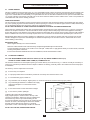
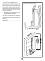
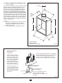
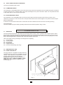
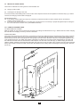
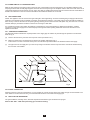
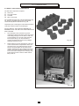
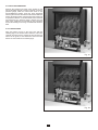
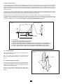
ATHENA
LF
ATHENA LF
Cat I2H G20 at 20mbar in GB and IE
FOR USE WITH NATURAL GAS ONLY
Installation & Servicing Instructions
G.C. No. 32 170 19
ÿ Product Code No. A88028
The Data Badge and Serial Number are located on the left hand side of the back panel.
PLEASE LEAVE THESE INSTRUCTIONS WITH THE USER
1
SERVICE AND INSTALLATION
CONTENTS LAYOUT
INTRODUCTION AND GENERAL INSTALLATION REQUIREMENTS
1.0 TECHNICAL DATA
2.0 CONDITIONS OF INSTALLATION
2.1
2.2
2.3
SITING GENERAL
FLUES AND CHIMNEYS
2.2.1 Brick Chimney, 178mm diameter (7 inch) Stone or Lined Flue and 125mm diameter (5 inch) Flue
2.2.2 Pre-Cast Flue
2.2.3 Metal Fluebox 125mm diameter (5 inch) Flues
SHELF HEIGHT AND SIDE CLEARANCES
2.3.1 Combustible Shelf
2.3.2 Non-Combustible Shelf
3.0 INSTALLATION OF FIRE
3.1
3.2
3.3
3.4
3.5
UNPACKING
PREPARATION OF FIRE
3.2.1 Spigot Restrictor
METHODS OF INSTALLATION
3.3.1 Fixing by Tension Cable
3.3.2 Fixing Directly onto Wall
GAS CONNECTION
3.4.1 Concealed Connection
3.4.2 Front Connection
TEST FOR GAS SOUNDNESS
4.0 COMMISSIONING
4.1
4.2
4.3
4.4
4.5
4.6
INSTALL FUEL EFFECT COMPONENTS
CHECK GAS PRESSURE
FIT TRIM AND FENDER
TEST FOR SPILLAGE
CHECK IGNITION
CHECK OPERATION OF FSD
5.0 INSTRUCT USER
6.0 SERVICING INSTRUCTIONS
6.1
6.2
6.3
6.4
6.5
6.6
6.7
6.8
6.9
6.10
6.11
REMOVE BURNER TRAY
MAIN BURNER INJECTOR
GAS TAP ASSEMBLY
PILOT ASSEMBLY
FUEL EFFECT COMPONENTS
MAIN BURNER
CONTROL KNOB
IGNITION UNIT
IGNITION BATTERY
IGNITION MICRO SWITCH
THERMOCOUPLE BREAK MICRO SWITCH
7.0 HINTS ON FAULT FINDING
8.0 SHORT LIST OF PARTS
2
INTRODUCTION
NO COMPONENT OF THIS FIRE IS MANUFACTURED FROM ASBESTOS OR ASBESTOS RELATED PRODUCTS.
The ATHENA L.F. is an open fronted inset live coal effect gas fire specially designed for Pre-Cast Flue application and is also
suitable for use with Brick Chimneys, twin walled or insulated Metal/Pre-fabricated Flues of 125mm minimum diameter and
Flueboxes conforming to the constructional requirements of BS 715. It is fitted with a combined flame supervision and oxygen
depletion monitoring device. The fire is for hearth mounting only on a non-combustible hearth. The fire is for use on Natural Gas
only.
GENERAL INSTALLATION REQUIREMENTS
In your own interest and that of safety, it is the law that all gas appliances are installed by competent persons in accordance with
the current Gas Safety (Installation and Use) Regulations. Failure to install appliances correctly could lead to prosecution.
The installation MUST be in accordance with these installation instructions, all the relevant parts of the Local and National Building
Regulations or Building Standards (Scotland) (Consolidation) Regulations and the relevant recommendations of the current editions
of the following British Standards:
B.S. 5871 : Part 2
B.S. 5440 : Parts 1 & 2
B.S. 6891
B.S. 6461 : Parts 1 & 2
B.S. 715
B.S. 1251
B.S. 1289 : 1975
B.S. 1289 : Part 1 : 1986
B.S. 1289 : Part 2 : 1989
Any other relevant British Standard Code of Practice and/or Local Building Regulations and in accordance with the rules in force.
1.0 TECHNICAL DATA
1.1
DIMENSIONS
(Overall)
mm
Height
Width
Depth
Forward Projection
Height to top of flue aperture
Weight
682
635
115
100
529
18 Kg
1.2 INPUTS AND PRESSURES
Maximum Heat Input (Gross)
Minimum Heat Input (Gross)
Supply Pressure
Setting Pressure Cold
Gas Rate Adjustment
6.0 kW
20470 Btu/h
2.3 kW
7848 Btu/h
20.0 mbar
13.0 mbar ± 1mbar
NONE
1.3 BURNER AND CONTROL DETAILS
Main Burner
Pilot Burner
Injector (Main Burner)
Ignition
Control Tap
Spark Gap
Control Knob Settings
ÿ 992174
SIT OP 9063
Bray Cat 82/440
Battery Operated Electronic Ignition. Battery Size 9V MN1604 or 6LR61
Concentric (with FSD) Model Number TESA 2762-025
3.0mm to 5.0mm
OFF, HIGH, MED, ECON, PILOT
3
2.0 CONDITIONS OF INSTALLATION
2.1
SITING GENERAL
This fire is suitable for hearth mounting only on a non-combustible hearth at least 13mm thick and measuring at least 630mm wide
by 330mm deep. Its top surface should preferably be 50mm above the floor level in order to discourage the placing of carpets or
rugs over it. It MUST NOT be fitted directly on a combustible wall. The fire should be installed so that no part of a combustible wall
i.e. not part of the fire surround but a full wall at 90o to the fire is less than 500mm from the radiant source. If this is not possible the
combustible side wall must be suitably protected.
FIREPLACE OPENING
The front opening of the fireplace must be between 305mm and 457mm wide and between 560mm and 585mm high (see Section
2.2). If the opening is greater it must be bricked up until the opening is a maximum of 585mm high and 457mm wide, alternatively a
non-combustible infill panel may be used to achieve the required dimensions.
DO NOT USE THE BACK OF A FIRE SURROUND OR MARBLE TO ACHIEVE THE ABOVE DIMENSIONS.
There must be a minimum flat surface area around the fireplace opening shown by the dotted lines in fig. 1 to ensure a good seal
between the fireplace and the fire. This area should be sound enough to take the wall plugs and screws supplied for front fixing.
Ensure that the base of the fireplace is level with the hearth and reasonably flat to prevent the fire rocking. Purpose built ventilation
bricks or additional air vents are not normally required in the room in which the fire is fitted unless specified by the rules in force.
IMPORTANT: When fitting any heating appliance or wallpapering a room in which one is fitted, soft wall coverings such as heat
sensitive wallpapers may become heat damaged or discoloured especially in the area above the fire. Please bear this in mind
when installing or decorating.
IMPORTANT NOTE
Plaster Applied Directly to Pre-cast Flue Blocks.
Some Pre-cast flues built to B.S. 1289:1975 may have plaster applied directly to the flue blocks.
A recommendation was made, in the revision B.S. 1289 part 1:1986, NOT to apply plaster directly to the flue blocks, otherwise
cracking of the plaster could occur.
It is not recommended to install this fire into such installations, unless remedial action is taken.
2.2
FLUES AND CHIMNEYS
2.2.1 SITE REQUIREMENTS FOR 228mm BY 228mm (9in BY 9in) BRICK CHIMNEY/178mm (7in)
STONE OR LINED CHIMNEY AND 125MM (5in) DIAMETER FLUE
The minimum dimensions for the fireplace opening for a brick chimney are as shown in Fig. 1. It will not normally be necessary to
remove any chair brick provided the minimum depth is obtained. A chimney previously used to burn solid fuel must be swept prior
to installation.
The chimney must be inspected to ensure that:
(a)
It serves only one fireplace.
(b)
It is properly sealed so that combustion products do not escape from the flue into the room.
(c)
It is not blocked by paper, rubble etc.
(d)
Any restriction such as damper, register plate, etc. must be removed or secured in the fully open position.
(e)
Any underdraught ventilation or additional air supply
entering the fireplace or on the hearth must be
sealed off.
(f)
It must have at least 3 metre effective flue height.
(g)
It must have a positive updraught.
IN
635 mm M
CHECK THE FLUE FOR GOOD DRAUGHT
Apply a lighted paper or smoke match to the top of the
opening in the fireplace. Observe if there is a definite flow
into the chimney and if so proceed with fitting the fire.
If no flow is indicated, warm the chimney for several minutes
and then re-check. If downdraught is observed a suitable
terminal must be fitted and the chimney re-checked.
If persistent no-flow or downdraught condition is observed
686 mm MIN
DO NOT FIT THE FIRE, SEEK EXPERT ADVICE.
Fig. 1
4
2.2.2 PRE-CAST FLUE OF MINIMUM SIZE (Fig. 2)
PRECAST FLUE INSTALLATION
This fire can be installed into a properly constructed pre-cast
flue conforming to B.S. 1289 : 1975 or B.S. 1289 : Part 1 :
1986 or B.S. 1289 : Part 2 : 1989 of at least 3 metres
effective height and having flueways of at least 198mm by
67mm or equivalent cross-sectional area with no dimension
less than 63mm. The fireplace opening width must be
between a maximum 457mm and a minimum 305mm. The
fireplace opening height must be between a maximum of
585mm and a minimum 560mm and a depth of at least
120mm above the hearth level.
NOTES:
1. The minimum dimensions for the flat area around the
opening are 686 mm high x 635 mm wide.
2. The flue spigot restrictor MUST NOT be fitted.
Ensure that any mortar fangs between the blocks do not
protrude into the flueways and if raking blocks are used they
are fitted according to the manufacturers instructions and
mortar is not allowed to drop down and accumulate in the
raked portions.
CHECK THE FLUE FOR GOOD DRAUGHT AS DETAILED
IN SECTION 2.2.1.
12
0
M I mm
N
X
MA
N
7
MI
45
5
30
5
686 MIN*
5
*
615 MAX
560 MIN
63
N
MI
Fig. 2
2.2.3 METAL FLUE BOX/125mm DIAMETER FLUES
(Figs. 3A and 3B)
This fire may be installed in a double walled or insulated
metal box built to the requirements of B.S. 715 e.g.
Selkirk, Product Code Number 0404805, using our
fixing kit G.C. Number 159 634 ÿ Number 992137.
The box must be lagged as detailed in Fig. 3B and
mounted on a non-combustible plinth at least 25mm
thick. Ensure that the base of the opening is level with
the hearth. A larger box built to the requirements of B.S.
715 and insulated as in Fig. 3B may be used. The front
opening must be as shown in Fig. 3A. The flue should
be twin walled e.g. Selkirk IL flues, or insulated type of
at least 125mm internal diameter and with a minimum
effective height of 3 metres. The depth of the opening
must be at least 200mm.
125 I/D
45
98 E
U
FL TRE
N
CE
20
0
610
560
NOTES:
1. If the flat area around the front opening of the box
is less than as specified in Fig. 1, it may be
necessary to use additional sealing material to
achieve a good seal.
2. The flue spigot restrictor MUST NOT be fitted.
7
40
7
FREESTANDING
GAS FLUE BOX
SELKIRK CODE 0404805
21
2
Fig. 3A
Refer to the following
illustrations for
configuration.
Note: The plaster board does not overlap the
edge of the fire housing. Any non-combustible
fire surround material used overlaps as
shown. The non-combustible fire surround
material must be sealed to the fire housing.
Cover the top, rear and
sides of the fire housing as
shown with 100mm (4in)
loft insulation material as
shown. If the gap between
the fire housing and any
combustible material is
less than 100mm, squeeze
the insulation material
between the two surfaces.
The minimum distance
from any studding or other
combustible material and
the flue pipe or any part of
the fire housing must be
25mm (1in).
Non-combustible fire
surround material
Non-combustible fire
surround material
Fire housing
The non-combustible material
must be sealed to the fire
housing to form an air tight seal
all around.
Sealant
Fig. 3B
6
2.3
SHELF HEIGHT AND SIDE CLEARANCES
The fire may be fitted beneath a shelf.
2.3.1 COMBUSTIBLE SHELF
The underside of a combustible shelf not more than 150mm deep must be at least 923mm from the hearth which gives a clearance
of 237mm above the fire. For deeper shelves, add 13mm shelf height for every 25mm increase in depth. For every 25mm decrease
in shelf depth subtract 13mm from the shelf height.
2.3.2 NON-COMBUSTIBLE SHELF
The underside of a non-combustible shelf not more than 75mm deep must be at least 25mm above the top of the fire. This
clearance is necessary for outer case removal. For deeper shelves, allow 13mm in shelf height for every 25mm increase in depth.
SIDE CLEARANCES:
A clearance of at least 25mm must be left on either side of the fire to facilitate removal of the outer case during servicing.
FIRE SURROUND:
The fire is suitable for purpose-made proprietary hearths/surrounds with temperature rating of 150oC.
3.0 INSTALLATION OF FIRE
3.1
UNPACKING
The fire is packed with the back coal and side cheeks already fitted in position. When unpacking refer to the check list to ensure
that all of the components are present and undamaged. Remove the top fitment from the carton. Lift the carton surround clear of
the fire. Remove the pack containing the coal bed and 9 loose coals. Remove the outer case from the fire, by lifting the it to clear
the two top locating brackets. Lift the fire clear of the bottom fitment of the carton.
Take out the polythene bag containing the fire fixing kit and comprising:
(i)
2 Fixing Cables
(ii) 2 Cable Adaptors
(iii) 2 Grub Screws
(iv) 4 Eye Screws
(v) 1 Spigot Restrictor
(vi) 4 Screws and Wall Plugs (fire fixing)
3.2
PREPARATION OF FIRE
3.2.1 SPIGOT RESTRICTOR
The spigot restrictor is supplied loose with the fire and
should be fitted only in the case of installation to a brick
chimney, 178mm diameter stone/lined flue of at least
3 metres effective height, with good draught.
DO NOT fit the spigot restrictor if installation is to a
PRE-CAST FLUE or a METAL FLUEBOX / 5 INCH
FLUE. Fit the spigot restrictor if applicable using
2 screws (Fig. 4).
SPIGOT RESTRICTOR
Fig. 4
7
2 SCREWS
3.3
METHOD OF INSTALLATION
There are two methods for securing the fire to the wall which are:
(a)
Fixing by tension cable.
(b)
Screwing the fire directly to the wall.
It is recommended, where drilling holes in the front face of the fireplace surround is unacceptable or otherwise risky e.g. a marble
surround, that fixing by tension cable is employed.
IMPORTANT NOTES
(a) If the surface of the fireplace is uneven it is necessary to prepare the surface so that a positive seal can be achieved
between the fire and the wall.
(b) If the fire is to be connected using a concealed gas connection then it is necessary to prepare the pipework prior to fitting the
fire to the wall. Refer to Section 3.4.1. (Concealed Connection).
3.3.1 FIXING BY TENSION CABLE
FIT MOUNTING EYE SCREWS
Mark the position for eye screws in the back of the opening according to the dimensions in Fig. 5. Drill the four 6mm holes and plug
the holes with the wall plugs. Fix the eye screws to the holes.
FIXING THE CABLE
First remove the burner tray (see Section 6.1). Insert the free end of each cable through the respective hole in the firebox and then
through the eye screws (refer to Fig. 5). Thread the free ends of the cable through the holes in the tensioning bolts located in the
base of the fire from the rear. Insert the fire into the opening so that the seal on the back of the fire is compressed against the face
of the fireplace/surround. Any visible gaps indicate a deviation from flatness of the surround face which MUST be corrected. Pull
the cable taut each side of the fire and insert the cable adaptors over the ends of the cable (Fig. 5). While keeping the cable taut
slide the adaptor against the tensioning bolt and tighten the grub screw to lock the cable. Using a spanner unscrew each tensioning
bolt by about 20mm to tension the cable. Prevent the cable adaptors from rotating while unscrewing the tensioning bolts. Refit the
burner tray.
Fig. 5
8
3.3.2 FIXING DIRECTLY TO SURROUND FACE
Mark the four positions of the fixing holes on the front face of the fireplace surround using the fire as a template. Drill 6mm holes
and plug the holes with the wall plugs supplied. Insert the fire into the opening in the fireplace until the seal on the back of the fire is
compressed against the surround face at every point. Note that any visible gaps between the surround face and the seal indicate a
deviation from flatness on the surround face and MUST be rectified. Screw the fire to the wall.
3.4
GAS CONNECTION
NOTE: The appliance must be connected to gas with rigid or semi-rigid tubing. A means of isolating the gas supply must be fitted
upstream of the appliance inlet to facilitate connection and subsequent servicing. The supply pipe to the fire should be installed so
that it is easy to remove the fire from the opening during servicing. Ensure that a service cock (which may be in the form of a union
restrictor elbow) is provided for isolation of the fire for servicing at a later date.
If a concealed connection from within the fireplace is required then, before the appliance is fitted into the fireplace, it will be
necessary to extend the supply line so that it will project through the sealed opening situated at the back of the firebox to the
appliance inlet elbow.
3.4.1. CONCEALED CONNECTION
The dimensions below indicate the required position of the supply pipe to enable it to pass through the aperture in the fire back.
Refer to Fig. 6.
(a)
Remove the burner tray from the fire to improve access (see Section 6.1).
(b)
Make connection from concealed point to finish in the position indicated in Fig. 6.
Ensure there is a union connection at this point. The inlet elbow provided with the fire should be fitted to the supply.
(c)
The pipe run from the supply line up to the rear opening in the firebox must be kept clear of the area which will be taken by
the box when it is installed.
73mm
115mm
Fig. 6
3.4.2 FRONT CONNECTION
After fixing the fire to the surround (Section 3.3) it is possible to connect the gas supply from either the right or left hand side. The
union elbow on the fire which has an RP1/4 internal thread should be connected to the supply pipe.
3.5
TEST FOR GAS SOUNDNESS
The gas installation, including metre, should be inspected and tested for gas soundness and purged.
Refer to B.S. 6891 : 1988 when performing gas soundness testing.
9
4.0 COMMISSIONING
4.1 INSTALL FUEL EFFECT COMPONENTS
The fuel effect components comprise:
(a)
(b)
(c)
(d)
Rear Coal
Two Side Cheeks
Coal Bed
Nine Loose Coals
The Coal Bed and the loose coals are illustrated in Fig.
7A. The fire is supplied with the rear coal and side
cheeks already fitted as illustrated in Fig. 7B.
Unpack the pack containing the coal bed and the loose
coals and check that these are undamaged.
DO NOT INSTALL THE FIRE WITH BROKEN OR
MISSING COALS. USE ONLY THE COALS SUPPLIED
WITH THE FIRE.
1.
2.
The underside of the coal bed has grooves
matching the raised ports of the burner top. Fit the
coal bed by placing it onto the burner. Take care
to avoid damage as you insert it past the pilot
burner (Refer to Fig. 7C). Ensure that it is
correctly located in the burner tray by sliding it
sideways and front to back.
Fig. 7A
Notice that there are five depressions at the front
of the coal bed and four depressions at the rear
(as shown in Fig. 7A). Place five loose coals in
the front recesses with their decorative faces
forward. Similarly place the remaining four loose
coals on top of the recesses formed by the front
loose coals and touching the rear coal (Fig. 7D).
Ensure that the loose coals are stable and not
likely to fall off.
Fig. 7B
10
4.2 CHECK GAS PRESSURE
Remove the pressure test point screw located on the
injector feed pipe just left of centre on the fire. Connect a
pressure gauge, slide the control knob down to the
PILOT/IGNITION position. Keep the knob depressed
after the pilot has lit to activate the FSD and then slide the
knob to the HIGH position. Check that the gas pressure is
as specified in Section 1.0 Technical Data. Turn off the fire
and disconnect the pressure gauge. Replace the test
point screw, relight the fire and test for gas soundness
around the sealing screw using a suitable leak detection
fluid.
4.3 FIT OUTER CASE
Align the bottom cut-outs in the outer case with the
retaining lugs on the firebox sides. Raise the outer case
vertically and then lower to engage the top onto the lugs
above the air guide, at the same time ensure that the
bottom cut-outs remain on the retaining lugs.
Fig. 7C
Fig. 7D
11
4.4 TEST FOR SPILLAGE
A test for spillage must be made before the installed fire is left with the user. This is carried out in the following manner. Light the
fire and leave at HIGH rate. Close all the doors and windows in the room and after the fire has been alight for five minutes insert
a lighted smoke match in line with the bottom edge of the canopy and 10mm below it (See Fig. 8). Hold the match with a pair of
pliers or in a metal tube. If all of the smoke is drawn into the fire the installation is satisfactory. if in doubt, repeat the test after a
further ten minutes.
If there is a fan or a fan operated appliance in a connecting room then the spillage test must be repeated with the fan running
and all inter-connecting doors between the fan and the fire left open. If the fan and the fire are in the same room, close all
windows and doors connected to the room. Switch on the fan and repeat the spillage test.
If spillage is detected, inspect the sealing of the fire to the surround / hearth. If this is satisfactory proceed as follows:
If a spigot restrictor was fitted, disconnect the fire and remove the spigot restrictor. Re-install the fire and repeat the above
spillage test. If there is still evidence of spillage then there may be a fault with the chimney or insufficient air in the room. if the
cause of the spillage cannot be corrected DISCONNECT THE FIRE AND SEEK EXPERT ADVICE.
Fig. 8
10.0
SMOKE MATCH
25.0
AIRBOX SIDE
1.
2.
3.
4.
5.
6.
7.
FIT CASE.
LIGHT FIRE AND LEAVE AT FULL RATE
CLOSE ALL DOORS AND WINDOWS
AFTER 5 MINUTES INSERT SMOKE MATCH AS SHOWN IN THE DIAGRAM.
SMOKE WILL BE DRAWN INTO THE FIRE IF INSTALLATION IS SATISFACTORY.
IF SPILLAGE OCCURS, WAIT FOR 10 MINUTES AND REPEAT THE TEST.
IF SPILLAGE IS STILL EVIDENT PROCEED AS IN FITTERS INSTRUCTIONS.
4.5 CHECK IGNITION
Fig. 9
Check that ignition of the pilot and the cross lighting to the
main burner is satisfactory.
NB. The spark gap between the electrode and
thermocouple tip should be between 3.0 and 5.0mm (See
Fig. 9).
3.0 - 5.0mm
4.6 CHECK OPERATION OF FSD
Leave the fire running on HIGH rate for 5 minutes and then
turn off the gas at the service cock. After 3 minutes turn the
service cock on again. If the gas has stopped flowing the
FSD has operated satisfactorily.
NOTE: You may hear the FSD valve close within the 3
minute period but always check that the gas has stopped
flowing.
12
5.0 INSTRUCT USER
Refer to Users Instructions
Make sure the user understands the following:
(a) How to light and operate the fire.
(b) The fire can be lit with a match or taper in the event of failure of the battery ignition.
(c) Demonstrate the removal and replacement of the coals. Advise on the need to clean these regularly.
(d) Advise that for safe and efficient operation, the fire should be serviced annually by British Gas or a CORGI registered service
agent.
(e) Explain to the user the functioning of the combined flame supervision and atmosphere monitoring device as detailed in
Section 6.4. Stress that if this device repeatedly shuts off the fire, the fault must be rectified immediately by a competent
person.
(f) When the fire is first lit a slight smell and light smoke may be noticed but this will clear away with a few hours of use on HIGH.
(g) Advise the user to carefully clean the base of the fire with a vacuum cleaner regularly.
Hand over the Users Instructions
6.0 SERVICING INSTRUCTIONS
IMPORTANT NOTES
1.
2.
3.
4.
5.
Turn off the gas supply to the fire before starting any servicing.
Always test for gas soundness after servicing or exchanging any component.
Remove the fire from the surround and inspect the catchment space for build up of debris on every service visit.
Check the fire for clearance of products on every service visit.
Remove any lint from the top of the main burner and from around the aeration hole of the pilot and main burner.
6.1
REMOVE BURNER TRAY
1.
2.
3.
4.
5.
6.
7.
Remove the outer case by lifting it upwards and away from the fire.
Remove the loose coals and coal bed.
Disconnect the gas supply at the inlet to the fire.
Remove the screw from the slider valve connection to the linkage.
Separate the yellow wires on the thermocouple break micro switch from the white wires attached to the pilot assembly.
Disconnect the red and blue wires from the ignition unit.
Remove the two screws securing the burner tray to the firebox and slide out the burner tray.
6.2
BURNER INJECTOR
1.
2.
3.
4.
5.
6.
Remove the burner tray (Section 6.1 above).
Undo the union nuts on the burner gas inlet and at the gas valve end and remove the gas pipe.
Undo the two screws securing the injector bracket to the burner manifold.
Undo the nut securing the injector to its holder, and remove the injector and washer.
Replace with the new injector.
Re-assemble in the reverse manner.
6.3
GAS VALVE / FSD ASSEMBLY
1.
2.
3.
4.
5.
6.
7.
8.
Remove burner tray (Section 6.1 above)..
Turn the tray upside down.
Undo the gas connections to the gas valve.
Release the thermocouple nut and ease out the probe.
Undo the two screws securing the burner to its tray and ease out the gas valve and gas inlet pipe.
Remove the two screws securing the gas valve to its bracket and remove the gas valve.
Replace with the new gas valve/fsd assembly.
Re-assemble in the reverse manner.
13
6.4
PILOT ASSEMBLY
The pilot is an atmosphere sensing device and must be replaced as a complete unit. Repair must not be undertaken.
NOTE: If the fire keeps going out or exhibits signs of nuisance shut off, check the operation of the pilot as follows:(a) Inspect the pilot flame, if suspect check the gas supply. Clear blockage if necessary. If flame is still suspect replace pilot
assembly.
(b) Check the thermocouple. If faulty replace the pilot assembly.
(c) Check the magnet unit in the gas valve. If faulty replace the valve.
(d) Check the thermocouple break micro switch and connections.
(d) Check the ventilation in the room. Vitiation may be due to lack of sufficient air supply.
(e) Check for satisfactory clearance of combustion products. Vitiation may be due to spillage of combustion products into the
room.
1.
2.
3.
4.
4.
5.
6.
7.
Remove burner tray (Section 6.1 above).
Release the pilot supply pipe at the pilot end and ease out the pipe.
Undo the thermocouple nut at the gas valve end and ease out the thermocouple.
Disconnect the thermocouple wires from the yellow micro switch wires.
Pull off the spark lead at the pilot end.
Remove the two screws securing the pilot assembly (and insulation pad) to its bracket.
Fit the new pilot assembly.
Re-assemble in the reverse manner.
6.5 FUEL EFFECT COMPONENTS
The loose coals and the coal bed simply lift out. To replace the rear coal and/or side cheeks proceed as follows:
SIDE CHEEKS
1.
Remove the outer case.
2.
Remove the left or right retaining panel by undoing the two screws securing it to the fire body.
3.
Slide out the side cheeks and replace with new ones. Re-assemble in reverse order.
REAR COAL
1.
Remove burner tray (Section 6.1)
2.
Remove the screws securing the lower coal support and slide out the rear coal.
3.
Replace with a new one, and re-assemble in reverse order.
6.6 MAIN BURNER
1.
2.
3.
4.
5.
6.
Remove burner tray (Section 6.1)
Undo the two screws securing the pilot assembly to the burner.
Undo the two screws securing the injector to the burner manifold.
Turn the tray upside down.
Undo the two screws securing the burner to the tray and remove the burner.
Fit the new burner and re-assemble in the reverse manner.
6.7 CONTROL KNOB
1.
2.
3.
Remove the outer case.
Remove the two screws securing the knob to the slider linkage.
Replace with a new knob and re-assemble in the reverse manner.
6.8 IGNITION UNIT
1.
2.
3.
4.
Remove the outer case.
Disconnect the red and blue wires and the ignition lead from the ignition unit.
Undo the two screws securing the ignition unit to its mounting bracket.
Replace with a new one and re-assemble in the reverse manner.
6.9 IGNITION BATTERY REPLACEMENT
1.
2.
3.
4.
5.
Remove the outer case.
The battery can now be located at the bottom of the fire, fitted into the ignition unit.
Remove the old battery from the ignition unit by pulling it out towards the right.
Replace with the new battery of the same type (see Section 1.0 Technical Data).
Note: The terminals of the battery are of different shapes to prevent incorrect connection. If it does not fit, try it the other way
round.
Re-fit the outer case.
14
6.10 IGNITION MICRO SWITCH
1.
2.
3.
4.
Remove the outer case.
Disconnect the red and blue wires from the ignition unit.
Remove the two screws securing the micro switch to the fire.
Replace with a new one and re-assemble in the reverse manner.
6.11 THERMOCOUPLE BREAK MICRO SWITCH
1.
2.
3.
4.
Remove the outer case.
Disconnect the thermocouple wires from the yellow micro switch wires.
Remove the two screws securing the micro switch to the fire.
Replace with a new one and re-assemble in the reverse manner.
7.0 HINTS ON FAULT FINDING
The following are possible fault conditions. Check the items mentioned and repair or replace parts as necessary. The list is not
exhaustive but a fair outline of possible faults.
1.
No Spark
(a) Check spark by manually operating the micro switch.
(b) The battery may be exhausted. Check and replace if necessary.
(c) Check the spark gap and electrode alignment. The electrode, thermocouple probe and horizontal arm of the pilot burner
should be in a straight line.
(d) Inspect the spark lead, ensure firm contact at the ends and that there is no shorting out of spark at either end.
2.
Spark but the pilot does not light.
(a) Verify availability of gas at the pilot burner, if possible, light with a match.
(b) If gas is available, proceed as in 1 above.
(c) If gas is not available, check the pilot burner and supply pipe for blockage.
(d) IMPORTANT: Remove the battery from the ignition unit to disable the spark ignition. Ensure gas is available at the pilot
port of gas tap, if not replace the tap.
3.
Pilot lights but goes out on heat setting.
Pilot starvation due to partial blockage. Clean the pilot gas supply line. See also 2(c) and 2(d) above.
4.
Nuisance shut off.
(a) Inspect the pilot flame.
(b) Check the thermocouple. If faulty replace the pilot assembly.
(c) Check the thermocouple break micro switch and connections.
(d) Check the magnet unit in the gas tap. If faulty replace the tap.
(e) Check the ventilation into the room. Vitiation may be due to the lack of sufficient air supply.
(f) Check for satisfactory clearance of combustion products. Vitiation may be due to spillage of combustion products into
the room.
5.
Main burner popping.
Remove the loose coals and coalbed. Light the fire and inspect the burner for cracks and leakage. Replace the burner if
necessary.
6.
Poor flame picture.
(a) Remove the burner assembly. Check the alignment of the burner ports with the holes in the coalbed. Ensure the ports
are clear.
(b) Re-assemble correctly and check the flame picture.
(c) Check the gas rate.
7.
Sooting.
Proceed as in 6 above.
8.
Spillage.
(a) Check the seal of the fire to the wall/surround.
(b) Inspect the chimney.
(c) Remove the spigot restrictor if fitted.
(d) Check the coal arrangement.
15
8.0 SHORT LIST PARTS
ÿ PART NUMBER
822309
990274
822308
993911
822238
992232
992234
992169
992178
992179
DESCRIPTION
Gas Valve / FSD Assembly
Control Knob
Pilot Assembly (Natural Gas)
Spark Lead
Ignition Unit
Rear Coal
Coal Bed
Loose Coals (9 off)
Left Side Cheek
Right Side Cheek
989882 Issue 2
ROBINSON WILLEY LIMITED
Mill Lane, Old Swan, Liverpool. L13 4AJ. England.
Telephone: 0151-228-9111 Fax: 0151-228-6661
www.robinson-willey.co.uk
16