1
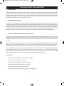
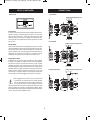
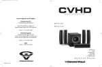
CXA Manual Rev 3_Manual_CXA_English_DB 1/31/2012 10:06 AM Page i
CXA-8 & CXA-10 AMPLIFIERS
OPERATION MANUAL
CXA Manual Rev 3_Manual_CXA_English_DB 1/31/2012 10:06 AM Page ii
WARNING
CXA Manual Rev 3_Manual_CXA_English_DB 1/31/2012 10:06 AM Page 1
Cerwin-Vega! CXA-8 & CXA-10 AMPLIFIERS
1.
INTRODUCTION
2.
UNPACKING & INSTALLATION
3.
ABOUT THE CERWIN-VEGA! CXA-8 & CXA-10 AMPLIFIERS
Congratulations! Welcome to the Cerwin-Vega! family. You’ve joined a growing group of audio professionals who have
turned to Cerwin-Vega! for the most advanced audio reproduction systems available. All Cerwin-Vega! systems are
thoroughly tested to insure that they meet or exceed our performance specifications. Backed by the best service in the
industry, Cerwin-Vega! is dedicated to quality and reliability. For a complete overview of Cerwin-Vega! products,
accessories, and services, log onto www.cerwin-vega.com.
Although it is neither complicated to install, nor difficult to operate your amplifier, a few minutes of your time are required
to read this manual for a properly wired installation, and to become familiar with the unit’s features. Please take great care
in unpacking the unit and do not discard the carton and other packing materials. They may be needed when moving the
unit and are required if it ever becomes necessary to return the unit for service. Never place the unit near a radiator, in
front of heating vents, in direct sunlight, in excessive humidity, or dusty locations to avoid damages and to guaranty a long
reliable use. Connect the unit with the system components according to the description on the following pages.
The Cerwin-Vega! CXA-8 & CXA-10 high performance stereo and bridgeable power amplifiers are for those that want to
sound like a pro! These home-use versions of the renowned Cerwin-Vega! Professional series amplifiers. The same
capability for shock and awe, but with input/output connections and a form factor suited for performing at home versus
on stage.
These workhorses have the muscle to accommodate the most demanding audio challenges. With power ratings of up to
1800 watts* (for the CXA-8) and 2800 watts* (for the CXA-10), exceptional THD (Total Harmonic Distortion) and Signal-toNoise ratings, the CV Series power amps are the right choice for a wide range of music and home theater applications.
To ensure reliable operation the CXA amps include a highly efficient variable speed tunnel cooling system that dynamically
follows amplifier output levels. The 21-position detent level control knobs help you set and maintain volume settings.
Signal and clip indicators provide a convenient way to monitor the amplifier’s status. Proven professionally -- the CXA-8 &
CXA-10 Amps are right for the job – even when the “job” is entertaining friends and family.
Main Features:
• Power ratings up to 2800 watts – run in stereo or bridged
• Professional quality design and reliability
• Flow-through cooling design prevents overheating
• Defeatable limiter and high pass filter per channel
• Detented 21-position input level control knobs
• Front panel LED indication of power, clip protect and signal status
1
CXA Manual Rev 3_Manual_CXA_English_DB 1/31/2012 10:06 AM Page 2
Cerwin-Vega! CXA-8 & CXA-10 AMPLIFIERS
CXA AMPLIFIER FRONT PANEL DESCRIPTION
Figure 1.1
1. Fan Vent
The CXA-8 & CXA-10 amplifiers are cooled by two rear-mounted
fans. Cool air flows through the front fan filters, reducing the
temperature of internal components while forcing the heat out
the rear vents. Never block these vents and keep them clean at
all times.
5. Active Indicators
These blue LED's indicate that AC power is connected and the
amplifier is turned on.
6. Protect Indicators
These red LED's indicate that the channel is in Protect mode.
When the channel goes into protect mode all output for that
channel will be muted. The protect LED's light when overheating
or other severe problems occur. This is to protect any speakers
connected to the channel. The LED's also light for approximately
five seconds whenever the unit is powered on and fade slowly
when the amplifier is powered off.
2. AC Power Switch
This switch powers the unit on and off.
3. Signal Indicators
These blue LED's will illuminate to indicate that a signal is
present at the amplifier input, and that the signal is being amplified.
7. Channel input level control
These two 21-position detented potentiometers adjust input
level for their respective amplifier channels. In Bridged Mono
Mode, only channel 1 level control is used to adjust signal level.
In Parallel Mode, both input level control are used to adjust signal level for their respective amplifier channels. At their fully
counter-clockwise position, the signal is attenuated by more
than 80dB. At their fully clockwise position, the signal is at maximum gain.When 0 dBu of signal arrives at the input jacks and
the Channel input level controls are set to their fully clockwise
position, the unit delivers full power output.
4. Clip Indicators
These red LED's will illuminate at the clipping threshold. These
lights should not light up during normal use as they indicate
signal outside of the amplification range of the amplifier. When
a signal is "clipped" and the clip indicator illuminates, it means
that the signal is being distorted at the output stage. Prolonged
clipping can not only damage your amplifier, but also your
speakers, so be careful to monitor the clip indicator during setup
and use. If the clip indicator is illuminated then simply lower the
channel gain or input signal until the indicator does not light.
2
CXA Manual Rev 3_Manual_CXA_English_DB 1/31/2012 10:06 AM Page 3
Cerwin-Vega! CXA-8 & CXA-10 AMPLIFIERS
CXA AMPLIFIER REAR PANEL DESCRIPTION
Figure 1.2
1. Fan
This is a variable speed cooling fan. Cool air enters the amplifier
through the fan filters located on the front of the amplifier. Be
sure not to block these ports when installing the amplifier or
other equipment.
2. Input connectors
Connect the input source to the unbalanced RCA connectors
using standard RCA cables.
3. Link connectors
These jacks are used to send a parallel signal to another device
or amplifier.
4. High Pass Filter (HPF) switch.
These switches are used to activate the built-in High Pass Filter.
The HPF rolls off signals below 40Hz. This improves bass performance by limiting sub-audio cone motion, making more
power available for the speaker’s rated frequency range. When
the filter is turned off, a 5 Hz roll off protects against DC or deep
sub-audio inputs.
5. Limiter switch
When the input signal connected to your amplifier is too high,
you end up with a distorted output signal. To prevent this, both
channels feature a clip limiter that can be engaged or disengaged selectively.
3
6. Bridge / Stereo / Parallel switch
This switch changes the amplifier operating mode between
stereo, mono bridged, and parallel.
7. 5-way Binding Post
Connect each channel of the unit to your speakers. Binding posts
are provided for each channel as so that paralleling of speakers
is possible. Connection to the binding posts can be made with
bare wire, banana plugs, or spade lug terminations. Make connections to both the Channel 1 and Channel 2 terminals for
Stereo or Parallel Mode, or a single connection across the red
terminals only of Channel 1 and Channel 2 for Bridged Mono
Mode.
8. Circuit breaker
The breaker acts in place of common disposable fuses. This circuit breaker will trip if there is a fault with the main voltage or
if maximum output is exceeded. Simply depress the circuit
breaker and power up the unit again.
9. AC input
IEC connector for AC power cable. Connect the supplied heavygauge 3-pin IEC power cable.
CXA Manual Rev 3_Manual_CXA_English_DB 1/31/2012 10:06 AM Page 4
PROTECTION
Every model in the CXA-Series incorporates protection features.
The front panel Protection LED indicates the activity of the
speaker connection relay circuitry in each channel.When the
protection LED turns on, this circuitry is active, and all connected
speakers are muted.
Initial power-up : For approximately five seconds after initial
power-up, the protection circuitry is activated and the speaker
outputs are muted. If everything is operating normally, you will
hear an audible click at the conclusion of this brief period, as
the protection circuitry is deactivated and the unit begins
delivering signal to the connected speakers. It is normal for the
Protection LED to fade gradually after the amplifier is powered
off.
Thermal Protection : Abnormally high heat sink temperatures
will engage the protection circuitry for the overheating channel
only. An output relay disconnects the speakers until normal
temperature range is restored. The Protect indicator will light
to show the protection circuit is active. To guard against this
problem, make sure the unit receives adequate ventilation on all
sides and that both the front and rear panels are unobstructed.
If the power transformer gets too hot, its thermal switch will
disconnect all of the secondary power and disconnect both
channel outputs.
Short circuit : If output is shorted due to faulty wiring, the
thermal circuitry will automatically protect the amplifier. If this
occurs, the load will be disconnected by the thermal protection
circuitry.
DC Voltage Protection : If an amplifier channel detects DC
voltage at the speaker output, the output relay will immediately
open to prevent speaker damage.
Subsonic Frequency Protection : The built-in High Pass Filter
provides subsonic frequency protection for each channel.
Current limiting Protection : At the amplifier’s full power limit,
or clipping point, the limiter circuitry will be activated. This is
indicated by illumination of the Clip LED. The channel gain is
automatically reduced, protecting the speakers from high
power. Uncontrolled feedback, oscillations, or improper
equipment gain setting may activate this circuitry, which is
virtually transparent in operation as full signal bandwidth is
maintained.
There is reason to be concerned any time the Protection LED
lights up (except for initial power-up during approximately five
seconds). If this occurs, turn the amplifier off immediately and
SETUP
Clip limiter
HPF (Hi-Pass Filter)
Limiter
Clipping is the result of an amplifier running into power supply
limitation. The maximum output voltage that any amplifier can
produce is limited by its power supply. Attempting to output a
voltage (or current) level that exceeds the power supply limit
will result in a flattening effect on the signal. A clipped waveform
exhibits extreme harmonic distortion, making it sound harsh or
dissonant. The clip limiter detects this and reduces the gain to
minimize the amount of overdrive. To preserve as much of the
program dynamics as possible, limiting reduces the average
program level until peaks barely clip. Each channel has its own
clip limiter, which can be switched on or off. When driving fullrange speakers, clip limiting reduces high frequency distortion
caused by bass overload. It also protects higher frequency
drivers from excess overdrive and harsh clipping harmonics.
Also known as a low-cut filter, a High Pass Filter rolls off signals
below 40Hz. The reproduction of the signal’s bass portion is thus
optimized, since ultra-low, distracting frequencies are
eliminated, and more power is available for the reproduction of
the wanted segment of the signal.
You should set up the filters so they best suit the frequency
response of your speakers, since some speakers are particularly
sensitive to over-excursion. The 40Hz filter works well with most
compact full-range speakers.
4
CXA Manual Rev 3_Manual_CXA_English_DB 1/31/2012 10:06 AM Page 5
SETUP (CONTINUED)
CONNECTIONS
Mode Select
Stereo Mode
(5-Way Ouptut Binding Posts)
Stereo Mode
In stereo mode, both channels operate independently with individual input gain controls. Signal at channel 1’s input produces output at channel 1, while signal at channel 2’s input
produces output at channel 2’s output. Recommended minimum nominal load impedance for stereo operation is 2 ohms
per channel.
Parallel Mode
Parallel Mode
When set to Parallel mode, a signal applied to channel 1’s input
will be amplified and appear at outputs for both channel 1 & 2.
The parallel mode is well suited for applications in which driving two speakers with the same signal but with separate amplification. The ‘Channel1’ and ‘Channel 2’ input gain controls
individually control the out put level on channels 1 and 2.
(5-Way Output Binding Posts)
Bridged Mono Mode
Bridged mono mode straps both amplifier channels together
to make a very powerful, single-channel monaural amplifier.
One channel ”pushes” and the other channel “pulls” equally,
doubling the power over that of either channel alone. Therefore the voltage is doubled, the peak power is quadrupled, and
program power is roughly three times as high as that of the individual channel. Signal is applied to the channel 1 input only
and channel 1 input gain control is used to adjust signal level.
The input gain control belonging to channel 2 are not used.
Bridged Mono Mode
Note : Bridged mono mode is to be used only when
the CXA-Series is connected to a 4 or 8 ohms speaker
load. Use of Bridged mode with speaker loads of less
than 4 ohms can result in severe damage to the unit
due to excessive heat and current limiting. Use extreme caution
when operating the amplifier in Bridged Mono Mode. Never
ground either side of the speaker cable; the speaker load must
“ float “ away from the amplifier chassis.
5
(5-Way Output Binding Posts)
CXA Manual Rev 3_Manual_CXA_English_DB 1/31/2012 10:06 AM Page 6
Cerwin-Vega! CXA-8 & CXA-10 AMPLIFIER SPECIFICATIONS
CXA-8
CXA-10
Stereo Both Channels Driven
Output Power (RMS)
8 ohms
400 W
600 W
4 ohms
600 W
900 W
2 ohms
900 W
1400 W
Output Power (RMS)
Bridged Mono
8 ohms
1200 W
1800 W
4 ohms
1800 W
2800 W
Signal to Noise Ratio (20 Hz - 20k Hz)
102 dB
104 dB
Distortion (SMPTE-IM)
0.01%
0.04%
Input Sensitivity @ 8 ohms
4 dBu
4 dBu
Voltage Gain
33 dB
35 dB
Output Circuitry
Class AB
Class H
Current Consumption
120V / 230V
@ 1/8 power @ 4 ohms
8.8 / 4.4 amps
6.8 / 3.4 amps
@ 1/3 power @ 4 ohms
12 / 6 amps
17 / 8.3 amps
@ Full power @ 4 ohms
19.5 / 9.5 amps
32 / 16 amps
20 Hz - 20k Hz @ 1/2 Power
0.01%
0.03%
1k Hz @ Full Power
0.10%
0.10%
Distortion
FREQUENCY RESPONSE
+/- 0.5 dB
20 Hz - 20 kHz
+/- 3 dB
5 Hz - 60 kHz
Damping Factor (400 Hz)
280
350
Input Impedance
15k ohm Un-balanced / 30k ohm balanced
Input Clipping
22 dBu (10 Vrms)
Continuously variable speed fan, front to rear
Cooling
CONNECTORS
Input
Unbalanced RCA input and link out
Output
5-way binding post
CONTROLS
Front
AC power switch / Channel 1 & 2 volume
Rear
HPF Switch / Limiter Switch / Mode Selector Switch
Indicators
Power On: Light Blue / Signal: Dark Blue / Limit-Clip: Red
Protection
Short Circuit / Thermal / Current Limit resetable breaker / DC offset /
Current In-Rush / RF Protection / On-Off Mute
Power Requirements
120V 60Hz (USA) / 230V 50Hz (EU)
Dimensions
Net Weight
482 X 101 X 420 mm
18 Kg
6
18.8 Kg
CXA Manual Rev 3_Manual_CXA_English_DB 1/31/2012 10:06 AM Page 7
Cerwin-Vega! A member of the Gibson family of brands
Gibson Customer Service • 309 Plus Park Blvd. • Nashville, TN 37218
Phone: 1-800-4GIBSON (1-800-444-2766)
E-mail: [email protected]
www.cerwin-vega.com
LITH00023 CXA OWNERS MANUAL © 2012 CERWIN-VEGA ALL RIGHTS RESERVED
This document is copyright protected. No part of this manual may be copied or reproduced in any form without prior written consent from CERWINVEGA. CERWIN-VEGA shall not be liable for operational, technical, or editorial errors/omissions made in this document.