1
MANUAL FOR MODELS
SMC40 SERIES INDEXER
December 3, 1999
#L010098
.
2
TABLE OF CONTENTS
SECTION 1 - INTRODUCTION.............................................................................................................................. 5
STEP MOTOR DRIVER ............................................................................................................................ 6
Technical Support...................................................................................................................................... 6
Ordering Information.................................................................................................................................. 6
SECTION 2 - QUICK START ................................................................................................................................. 7
10 QUICK STEPS – Tutorial Program ....................................................................................................... 7
SECTION 3 - STEP MOTOR DRIVER ................................................................................................................. 13
MODEL – DPD72401, DPK72402, & DPK72403 (BLD72 Driver) ............................................................. 13
BILEVEL DRIVE ..................................................................................................................... 13
HALF-STEP/FULL-STEP ........................................................................................................ 13
MOTOR ON/OFF INPUT ........................................................................................................ 13
FAULT PROTECTION ............................................................................................................ 13
SETTING THE KICK CURRENT ............................................................................................................. 13
GROUNDING .......................................................................................................................................... 13
MOTOR CONNECTIONS........................................................................................................................ 14
WIRING DIAGRAM................................................................................................................. 14
MODEL – DPD60401............................................................................................................................... 15
MODE SELECT SWITCHES ................................................................................................ 15
MICROSTEP SELECTION ..................................................................................................... 15
ADJUSTING THE RUNNING CURRENT ............................................................................. 16
REDUCING OUTPUT CURRENT ......................................................................................... 16
MOTOR DRIVER CONNECTIONS ....................................................................................... 16
STEP MOTOR CONFIGURATIONS ....................................................................................... 16
SECTION 4- FEATURES ..................................................................................................................................... 18
PRODUCT HIGHLIGHTS ........................................................................................................................ 18
ENCODER FEEDBACK........................................................................................................................... 18
PLC TYPE FUNCTIONS ......................................................................................................................... 18
MULTIPLE PROGRAMS ......................................................................................................................... 18
VARIABLES ............................................................................................................................................ 18
REGISTERS........................................................................................................................... 18
BITS ....................................................................................................................................... 18
MOTION STATUS BITS ......................................................................................................... 19
EXTERNAL MODULES ........................................................................................................................... 20
THUMBWHEEL SWITCH........................................................................................................................ 22
REMOTE PANEL MOUNT....................................................................................................................... 22
Installation .............................................................................................................................. 22
SECTION 5 - INSTALLATION.............................................................................................................................. 23
UNIT SELECTION................................................................................................................................... 23
BAUD RATE SELECTION ....................................................................................................................... 23
INSTALLATION – MOUNTING OPTIONS ............................................................................................... 23
DIMENSIONS - DRIVER PACKS ............................................................................................................ 24
INDEXER TERMINAL BLOCK AND SWITCH LOCATION....................................................................... 24
DIMENSIONS – PCL402 & PCL403 ........................................................................................................ 25
DIMENSIONS - SMC40M - 24I ................................................................................................................ 26
AC POWER CONNECTION AND FUSE ................................................................................................. 27
Single axis INDEXER CONNECTIONS.................................................................................................... 28
PCL INDEXER CONNECTIONS.............................................................................................................. 29
INDEXER INPUTS (Flat ribbon header).................................................................................................. 30
INDEXER OUTPUTS (Flat ribbon header) ............................................................................................... 30
MOTOR CONNECTORS......................................................................................................................... 31
PCL HOOKUP DIAGRAM........................................................................................................................ 32
SECTION 6 - COMMUNICATIONS ...................................................................................................................... 33
TALKING TO THE INDEXER .................................................................................................................. 33
RS232 ..................................................................................................................................................... 33
RS422 ..................................................................................................................................................... 33
3
HANDSHAKING SIGNALS ...................................................................................................................... 34
DTE VS DCE........................................................................................................................................... 34
“A MANNER OF SPEAKING” .................................................................................................................. 35
RTS DEFINED ........................................................................................................................................ 35
CTS DEFINED ........................................................................................................................................ 35
SECTION 7-INTELLIGENT SOFTWARE ............................................................................................................. 36
DESCRIPTION........................................................................................................................................ 36
INSTALLATION....................................................................................................................................... 36
SOFTWARE DEFAULTS ........................................................................................................................ 36
THE FOUR PROGRAMS ........................................................................................................................ 37
MAIN PROGRAM ................................................................................................................... 37
PROGRAM 1, 2 and 3............................................................................................................. 37
MULTITASKING ..................................................................................................................... 37
ADDING, INSERTING, CHANGING OR DELETING A COMMAND ........................................ 37
AUTOSTARTING .................................................................................................................................... 38
SECTION 8 - COMMAND DESCRIPTIONS ......................................................................................................... 39
BRANCHING COMMANDS ..................................................................................................................... 40
START/ STOP COMMANDS ................................................................................................................... 42
MOTION PROFILE.................................................................................................................................. 44
OUTPUT COMMANDS............................................................................................................................ 46
USER ENTRY COMMANDS.................................................................................................................... 47
PROGRAM 1, 2, 3 ................................................................................................................................... 48
ENCODER COMMANDS......................................................................................................................... 49
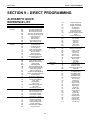
SECTION 9 – DIRECT PROGRAMMING............................................................................................................. 51
ALPHABETIC QUICK REFERENCE LIST ............................................................................................... 51
TALKING WITH A TERMINAL (TT1R2-1)................................................................................................ 53
DIRECT PROGRAMMING QUICK START .............................................................................................. 54
TERMINAL COMMANDS (SMTNR2-1 and TT1R2-1) .............................................................................. 55
SECTION 10 - SPECIFICATIONS ....................................................................................................................... 56
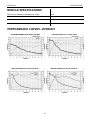
PERFORMANCE CURVES –DPD60401 ................................................................................................. 57
SECTION 11 - TROUBLESHOOTING ................................................................................................................. 59
SECTION 12 – ERROR CODES .......................................................................................................................... 60
BLINKING ERROR CODES (INDEXER).................................................................................................. 61
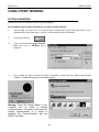
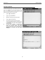
USING HYPER TERMINAL ..................................................................................................................... 62
CLEARING ERROR CODES ON THE SMC40 ........................................................................................ 66
SECTION 13 - GLOSSARY ................................................................................................................................. 68
APPENDIX A – ASCII CODE TABLE ................................................................................................................... 70
4
SECTION 1
INTRODUCTION
SECTION 1 - INTRODUCTION
This manual is intended to help the user apply
the SMC40 family of products in motion control
applications.
Familiarity
with
computers,
programmable logic controllers (PLC's), or
terminals is helpful, but is not essential.
Almost all computers have, or can be equipped
with, an RS232 port. If you wish to send your
RS232C signal over 50 feet, Anaheim
Automation manufactures a RS232C to RS422
Data Converter (Model DC1709).
The SMC40 family of products is based on
Anaheim Automation’s advanced step motor
controller integrated circuit. This high speed
microprocessor uses a simple language that can
access over 125 different commands. These
commands deal with motion parameters,
encoders, inputs and outputs, variables, math
functions, and much more. This functionality
produces a very powerful step motor indexer
that is able to handle even the most
complicated machine control.
Expansion
Modules have been added for this series to
include easy use of external thumbwheel
modules, external terminals, and additional
inputs.
The SMC40 provides programming of
acceleration, base speed (start up speed),
running speed, and the number of steps to be
taken in both relative and absolute positioning
modes. On absolute positioning moves, the
SMC40 automatically determines the proper
direction to go and the number of steps to take.
The relative positioning will move a number of
steps in the direction that the user defines. The
SMC40 has a high level command set including:
looping, conditional statements, time delays,
power down motor, encoder feedback,
maskable I/O and open-collector (NPN) outputs.
Hard, Soft, and Home Limit Switch inputs are
provided for each axis. These features are
generally required in most machine control
designs. 96 Inputs and 24 Outputs are provided
per unit. These I/O may be used for monitoring
and controlling machine operation and/or
interaxis coordination. These I/O are accessible
independent of the busy state of the axis
controls.
The Inputs are TTL/CMOS
compatible. The Outputs are current sinking,
open collector darlingtons.
The SMC40 has two modes of operation: Direct
Mode and Stored Program Mode. In Stored
Program Mode a whole program is stored in the
SMC40’s internal memory (16,000 bytes). Once
a program has been sent to memory, it is nonvolatile meaning if the power is turned off, the
program will still remain in the memory. In
Direct Mode, commands are sent to the unit via
a serial port and are executed one command at
a time.
The SMC40 has a built-in programmable reset
circuit so that all axes in the daisychain may be
reset. The outputs are reset to the off state
when the board is reset. Reset is automatic on
power-up or with a "break" signal on the RS232
or RS422 input. Windows software is provided
when you purchase the unit. This software
allows you to write and change programs that
are to be stored in the SMC40 for autostart use.
The software also allows you to save the
programs onto your computer disk, and easily
retrieve them when needed. The program can
upload the stored program from the SMC40,
allow you to make changes, and then download
the program back to the SMC40.
A step motor is essentially a digital device. If
you give the step motor driver 10 clock pulses
the motor moves 10 steps. Sometimes a
closed-loop system is needed to verify that the
motor indeed moved 10 steps. The SMC40 will
accept encoder inputs to form a closed-loop
system.
The SMC40 is designed to communicate over a
RS232C or RS422 bi-directional serial data bus.
The RS422 serial bus is better suited for
industrial
environments
susceptible
to
electrically noisy conditions. RS422 can reliably
travel to a distance of 4000 feet. The RS232C
line can only be used to a distance of 50 feet in
a noise free environment.
5
SECTION 1
INTRODUCTION
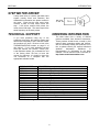
STEP MOTOR DRIVER
A step motor driver is a device that takes input
signals (usually Clock and Direction) and
translates this information into phase currents in
the motor. Each time the step motor driver
receives a pulse, the step motor moves one
step. If the driver receives 200 pulses, the
motor moves 200 steps. The motor steps at the
same frequency as the clock pulses.
ORDERING INFORMATION
TECHNICAL SUPPORT
The table below lists a variety of SMC40
products available from Anaheim Automation.
These products include those covered by this
manual along supporting cables and devices.
We are continually adding new products to our
line, so please consult your nearest Authorized
Anaheim
Automation
Distributor
or
Representative for information on the latest
releases. We can also be found on the web, at:
http://www.anaheimautomation.com
If you have problems using any of the
equipment covered by this manual, please read
this manual completely to see if that will answer
the questions you have. Be sure to look in the
TROUBLESHOOTING section on page 51 of
this manual. If you need assistance beyond
what this manual can provide, contact your
Local Distributor where you purchased the unit
or the factory direct. Be sure to have this
manual for reference. It is helpful to have the
unit connected to a computer with the
appropriate software loaded.
MODEL NUMBER
DPD72401
DPD60401
DPK72402
DPK72403
DESCRIPTION
Single-Axis Intelligent Driver Pack,
Single-Axis Intelligent Microstep Driver Pack,
Dual-Axis Intelligent Driver Pack,
Triple-Axis Intelligent Driver Pack,
PCL401
Single-Axis Intelligent Standalone Controller
PCL402
Dual-Axis Intelligent Standalone Controller
PCL403
Triple-Axis Intelligent Standalone Controller
SMC40M-24I
24 Input Expansion Module
SMC40M-TWS7
Thumbwheel Expansion Module
AA2M50
50 Pin Breakout Terminal Board
AA2682
50 Pin Ribbon Cable Assembly, 2 Feet
AA9FMC-6
Serial Cable, 6 Feet
SMTNR2-1
Remote Panel Mount Programmer/Terminal
TT1R2-1
Handheld Programmer/Terminal
TABLE 1: Ordering Information
6
1 - 7 Amp
1 - 6 Amp
1 - 7 Amp
1 - 7 Amp
SECTION 2
QUICK START
SECTION 2 - QUICK START
You will need:
Driver Pack (Single Axis)
Compatible Step Motor
Serial Cable
Computer with Windows 3.1 (or above)
Intelligent Indexer Software Package
Switch
5VDC LED or Equivalent (Optional)
10 QUICK STEPS – TUTORIAL PROGRAM
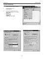
STEP 1 - Install the Software
To install the SMC40 Software refer to Section 7 - Intelligent Software
STEP 2 - Setup the Software
Run the Intelligent Indexer Software by Double Clicking the SMC40 Icon in Windows.
The Defaults are:
Com Port
Com1
Baud Rate
9600
Units
Steps
Number of Axes
1
7
SECTION 2
QUICK START
STEP3 - Connect a Motor
Connect the step motor. Use Section 3, Motor Hook Up to assist. Set the Kick Current to match the
motors rated phase current. The kick current potentiometer is located on the driver side labeled Kick
Current Adjust. Whenever you are connecting wires to the Driver Pack, be certain that the power is
off or significant damage can occur.
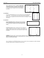
STEP 4 - Connect the Switch and (Optional) LED
This switch is used as a “start switch” to cause the Driver Pack to begin sequencing through the program.
Connect one side of the switch to Pin #1 (Input #1) and the other side of the switch to Pin #5 (0 VDC).
The LED is optional. The LED demonstrates how an Output can be turned on and off. Connect the
Anode side of the LED to Pin # 11 (+5 VDC) and the Cathode side of the LED to Pin #13. Note: A
resistor must be placed in series with the LED to limit the current. A +5V LED has the series resistor
internally connected.
Pin #
Description
1
Input #1
2
Input #2
3
Input #3
4
Input #4
5
0 VDC
6
Input #5
7
Input #6
8
Input #7
9
Input #8
Table 3: Connector TB3 Pinout
Pin #
10
11
12
13
14
15
16
17
Description
0 VDC
+5 VDC
Clamp
Output #1
Output #2
Output #3
Output #4
0 VDC
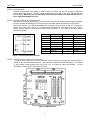
Figure 1: Connect the Switch and LED
STEP 5 - Connect the Serial Cable to the Driver Pack
To connect your computer to the Driver Pack you need to connect the serial ports (usually COM1 or
COM2) to the units lower DB9 connector. This connector is labeled RS232/RS422 IN (P1). It is helpful
to know which communications port (Com Port) is in use when we setup the software. In most
computers, a 9 pin Male to Female cable will work.
Figure 2: SMC40 Indexer
8
SECTION 2
QUICK START
STEP 6a - Set up the Communication Slide Switch to RS232
Refer to Figure 2 (silkscreen) on the side of the Driver Pack for the slide switch placement
STEP 6b - Set up Unit Number
Refer to Figure 2 or silkscreen on the side of the Driver Pack for the rotary switch setting (SW3).
Note the Default Unit Address 0 corresponds to Axis X.
STEP 6c - Set up the Baud Rate
To locate the Baud Rate Switch (SW4) refer to Figure 2. It is the silkscreened table on the Driver Pack.
Note: the default is 9600 ( position 5) on the Baud Rate Switch (SW4). Refer to Section 5, page 23 for
further assistance when selecting the Baud Rate.
STEP 6d - Power-up the Driver Pack
Plug in the Driver Pack. Standard models DPD/DPF7240_ Series, DPFEN403, DPF11401 and DPD60401
are supplied with a detachable linecord which is plugged into a standard wall socket (115VAC, 60 Hz).
The above models are available with a X250 suffix. These units are configured to accept a wide variety of
voltages. You must configure the terminal block to handle the desired voltage level. (Refer to Section 4,
page 26 for X250 Version).
STEP 6e - Press the Connect Icon Button
ê
If everything is connected properly, a green “Connected” indicator will be displayed on the top right hand of
the screen.
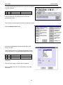
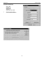
STEP 7 - Write a Program
The Software automatically comes up with the file
SMC40.MDB selected. This will be a blank
program. When you save the program you will
need to give it
another name.
We will save our
program as
TEST1.
There are four program areas that your program may reside in. You will be using the Main Program Area for this
test program.
9
SECTION 2
QUICK START
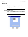
To begin programming place the cursor on the line you wish to
enter the command.
Line
8 1
Command
Parameter 1
Select the Add button by clicking it once on the main
programming screen.
é
This will take you into the select command programming screen.
Select the Motion Profile Button.
è
Select the highlighted Base Speed and enter 500 for the
Value. Click OK.
This will take you back out to the main programming screen.
You will see that line 1 now reads Base Speed 500 on Line 1.
Line Command
Parameter 1
1
Base Speed
500
8 2
Repeat the same process when entering the rest of the
commands.
Turn to the next page to continue the test program.
Note: For Single-Axis units, an X will precede many of the
commands.
10
SECTION 2
QUICK START
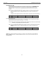
The following is an overview of the program you will write:
The initialization of the parameters will be set up first. Base Speed will be set to 500 steps/sec, Max Speed to 1000
steps/sec, and Ramping (Accel / Decel) to 10000 steps/sec. Next, you will wait for Input #1 to go to Low (0VDC).
While waiting or pausing for the input to go low ( 0VDC), the motor current will be turned off. When Input #1 goes
to 0VDC, motion will start. The motor will move in the Clockwise direction 400 steps. Output #1 will be set to 0VDC
(Refer to Section 8 on Command Descriptions for further assistance), a wait delay of one second will occur and
the output will be reset back OFF (+5VDC). This procedure will be looped four times. The program will repeat if
Input #1 goes to 0VDC. Place Branch Quit commands on all Four Programs, even if they are not utilized.
8
Line
1
2
3
4
5
6
7
8
Location of Command
Motion Profile
Motion Profile
Motion Profile
Branching \ Label
Motion Profile
Branching \ If(bit)Then
Branching \ Label
Branching \ For Loop \
Loop Top
Command
XBase Speed
XMax Speed
XAccel/Decel
Label
XCurrent Hold
If I1 = 0
Label
Loop Top
Start Motion
Value to be Entered
Enter Value of 500
Enter Value of 1000
Enter Value of 10000
Enter Label as Pause
Enter Value of 0
Then Branch to Label
Start Motion
Parameter 1
500
1000
10000
Pause
0
Then Start
Motion
Else Then Branch to
Label Pause
Start Motion
Click Loop Top
Start Motion
4 Times
Parameter 2
Else Pause
Enter on Loop Top
Label Start Motion.
9
10
11
12
13
14
15
16
Motion Profile
Start/Stop
Outputs
Branching \ Wait Delay
Output
Branching \ For Loop \
Loop Bottom
Branching \ Goto \ Label
Branching \ Quit
XDir+
XGo Relative
Set Outputs
Wait Delay
Set Outputs
Loop Bottom
Start Motion
Goto
Branch Quit
Enter 4 in Number of
Times.
Choose Dir+
Choose Go Relative
Click OUT1 ON
Enter Value of 1000
Click OUT1 OFF
Click Loop Bottom.
400
ON:1
1000
ON:
OFF:
OFF:1
Enter on Loop Bottom
Label Start Motion.
Enter Label as Pause Pause
Click OK
Refer to the Command Column in the program table above for programming assistance. Note that the Location of
Command Column will help locate the commands needed. Note that Command Locations are in levels for
example step1\ step2\ step3. The Parameters will be the values and labels necessary to complete the test
program.
Note: If your program has problems and is showing errors:
1. Save your program by giving it a name.(Example: Test1)
2. Power down the Indexer momentarily, then Power Up.
3. Reset the Indexer at the Menu heading under Setup
4. Click the Connect Button ( Upper Right most button).
5. Programs are Auto Saved so that you may resume where you left off.
11
SECTION 2
QUICK START
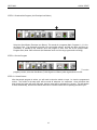
STEP 8 - Download the Program ( the Envelope Icon Button )
ê
Select the Send Button (Envelope Icon Button). This sends all 4 programs (Main, Programs 1, 2, & 3 to
the Driver Pack. The programs will reside in the nonvolatile memory, and will stay there until they are
overwritten, or deleted by the software. Once the program is sent, Click OK on the prompt button
Program Sent. (Note: Place a Branch Quit Statement at the end of every program before sending.)
STEP 9 - Run the Program
ê
To run the
program just sent, select the Start Button (Traffic Signal Icon Button) which signals Green for GO.
STEP 10 - Switch Closure
After the sample program is written, you will need to close the switch on Input 1 to view the programmed
motion. The current to the step motor will be turned off whenever it is motionless. Once the switch has
been closed, the motor will move 400 steps, then an output will be activated for 1 second. This will happen
4 times automatically, and then the indexer will wait for a switch closure before repeating the same cycle.
12
SECTION 3
STEP MOTOR DRIVER
SECTION 3 - STEP MOTOR DRIVER
MODEL – DPD72401, DPK72402, & DPK72403 (BLD72 Driver)
BILEVEL DRIVE
The basic function of a step motor driver is to provide the rated motor phase current to the motor windings in the
shortest possible time. The bilevel driver uses a high voltage to get a rapid rate of current rise in the motor
windings in the least amount of time. When reaching the preset trip current, the driver turns off the high voltage
and sustains the current from the low voltage supply.
HALF-STEP/FULL-STEP
Users have a choice of full-step operation or half-step operation. Full-step operation occurs by energizing two
phases at a time, rotating a typical motor 1.8 degrees per step. Half-step operation occurs by alternately
energizing one, and then two, phases at a time, rotating the motor 0.9 degrees per step. Full-step operation is
suggested for applications that specifically require that mode, such as when retrofitting existing full-step systems.
MOTOR ON/OFF INPUT
The motor on/off input allows de-energizing a motor without disturbing the positioning logic. After re-energizing
the motor, a routine can continue. This reduces motor heating and conserves power, especially in applications
where motors are stopped for long periods and no holding torque is required. If holding torque is required (such as
when lifting a load vertically), then this function should not be used. This output is internally connected to the
Indexer. See Section 8 Command Descriptions for further information on Current Hold Command.
FAULT PROTECTION
There are 3 types of fault detection. When a fault is detected, the driver turns off the motor current and the red
Fault LED indicates which type of fault occurred. (Located on the top of the driver pack.)
1
LED - Slow Blink
shorted wire in the motor or cable
2
LED - Fast Blink
open wire in the motor or cable
3
LED - ON Steady
ground fault (voltage shorted to 0V)
TABLE 3: FAULT LED
If the driver goes into a fault condition, the fault may be reset by turning the power OFF for at least 15 seconds or
by pulling the RESET FAULT input (terminal 4) to a logic “0" for at least 100ms.
SETTING THE KICK CURRENT
The Kick Current should be set to the Motor’s Rated Unipolar Current. For example, a 34D309 is rated for
4.5A, so the Kick Current Potentiometer would be set somewhere between the 4A and 5A indication.
GROUNDING
The unit should be properly grounded. Shielded cable should be used to preserve signal integrity.
Contact factory for grounding recommendations.
13
SECTION 3
STEP MOTOR DRIVER
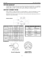
MOTOR HOOKUP
The DPD72401 Series Driver Packs can drive 6-lead and 8-lead step motors rated from 1 to 7 amps/phase
(unipolar rating). It features a unipolar bilevel (dual voltage) drive technique with short/open circuit
protection (with a Fault LED). This Driver Pack contains a 300 Watt fan cooled power supply.
MOTOR CONNECTIONS
Refer to Section 4 on Motor Connectors for a hookup diagram for Driver Pack applications. All motor
connections must be separated from input connections and all other possible sources of interference.
IMPORTANT NOTE: When wiring from the driver(s) to the step motor(s) that extends beyond 25 feet, it is
important to consult with the factory.
WIRING DIAGRAM
14
SECTION 3
STEP MOTOR DRIVER
MODEL – DPD60401
The DPD60401 will deliver a peak current of 5.5 Amperes per phase at 65 Volts, providing outstanding
motor performance. This advanced technology reduces ripple current while maintaining the 20kHz
chopping frequency in the motor, causing less heat in both the motor and drive.
MODE SELECT SWITCHES
The MODE SELECT SWITCHES are used to select the divisor of operation from divide by 2 up to divide
by 256. Microstep operations are recommended for those applications that specifically require this drive
technique, such as retrofitting existing microstep systems. Microstep applications are mainly used for very
slow speed operations that require high resolution or very smooth performance. This enhanced resolution
can only be accountable for positioning accuracy of a step motor typically ±5% of one full step when
dividing by 20 (step angle of .09°) or less. Anaheim Automation recommends the use of the bilevel drives
that have a divide by 2 (halfstep mode) for operations ranging in speeds higher than 2Khz, since
smoothness can easily be accomplished at this rate.
MICROSTEP SELECTION
The number of microsteps per step is selected by the dip switch(SW1). Table 6 shows the standard
resolution values along with the associated settings for these switches. The standard waveforms are
sinusoidal.
Resolution
Steps/
Rev
Switch 1
Switch 2
Switch 3
Switch 4
2
400
ON
ON
ON
ON
4
800
OFF
ON
ON
ON
8
1,600
ON
OFF
ON
ON
16
3,200
OFF
OFF
ON
ON
32
6,400
ON
ON
OFF
ON
64
12,800
OFF
ON
OFF
ON
128
25,600
ON
OFF
OFF
ON
256
51,200
OFF
OFF
OFF
ON
5
1,000
ON
ON
ON
OFF
10
2,000
OFF
ON
ON
OFF
25
5,000
ON
OFF
ON
OFF
50
10,000
OFF
OFF
ON
OFF
125
25,000
ON
ON
OFF
OFF
250
50,000
OFF
ON
OFF
Open
TABLE : Mode Selections
Note: The Microstep Mode Select switches are located on the top cover of the DPD60401.
15
SECTION 3
STEP MOTOR DRIVER
ADJUSTING THE RUNNING CURRENT
The output current on the Microstep Driver Pack (DPD60401) is set
by the Running Current Potentiometer. This resistance determines
the per Phase RMS output current of the driver. Refer to table on
Running Current Settings.
REDUCING OUTPUT CURRENT
The amount of current per Phase in the reduction mode is related to
the value of the current adjustment potentiometer (Running Current)
and the current reduction potentiometer (Reduced Current). When
the current reduction circuit is activated, the Reduced Current
resistance is paralleled with the Running Current resistance. This
lowers the total resistance value, and thus lowers the per Phase
output current by a percentage.
Running Current
Potentiometer Setting
1
2
3
4
4
5
5.5
Current
(Amps)
1.4
2
3
4
4.5
5
5.5
Pot 1.4 AMPS 2 AMPS 3 AMPS 4 AMPS 5 AMPS 5.5 AMPS
1
50%
42%
32%
26%
22%
21%
2
61%
53%
43%
36%
31%
30%
3
70%
64%
54%
46%
41%
39%
4
75%
70%
61%
54%
48%
46%
5
80%
75%
67%
59%
54%
52%
6
82%
78%
71%
64%
58%
56%
7
84%
81%
75%
68%
63%
61%
8
86%
84%
77%
71%
66%
64%
9
89%
88%
83%
78%
74%
72%
TABLE : Percentage of I(peak) settings on Reduced Current Potentiometer
Note: To obtain a proper setting, adjust the potentiometer arrow to the setting that corresponds to the rated
current of the step motor in use. Use the resistance tables that match resistance to rated motor currents.
MOTOR DRIVER CONNECTIONS
Wiring from the Driver Pack to the motor should be routed away from all other wiring. All electrical
connections are made to screw-type terminals for secure and reliable connections. Refer to Section 5,
Installation.
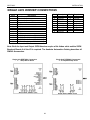
STEP MOTOR CONFIGURATIONS
Step motors can be purchased in configurations of 4, 6 or 8 leads. Each configuration requires different
current settings. Different lead configurations and the procedures to determine their output current are
shown below .
6 Lead Motors
When configuring a 6 lead motor in a half-coil
configuration (connected from one end of the coil to
the center tap) use the specified per Phase (or unipolar)
current rating to determine the current adjustment pot
setting. This configuration will provide more torque at
higher speeds.
16
SECTION 3
STEP MOTOR DRIVER
When configuring the motor in a series configuration
(connected from end to end with the center tap floating)
multiply the per Phase (or unipolar) current rating by
0.7. Use this result to determine the current adjustment
pot setting.
4 Lead Motors
Use the specified series motor current to determine the current adjustment
resistor value. Four-lead motors are usually rated with their appropriate
series current, as opposed to the Phase Current which is the rating for 6 and 8
lead motors.
8 Lead Motors
Series Connection: When configuring the motor windings in
series, multiply the per Phase (or unipolar) current rating by
0.7. Use this result to determine the current adjustment pot
setting.
Parallel Connection: When configuring the motor windings in
parallel, multiply the per Phase (or unipolar) current rating by 1.4.
Use this result to determine the current adjustment Output Current
pot setting.
WARNING! Step motors will run hot even when configured correctly. Damage may occur to the motor if a
higher than specified current is used. Most specified motor currents are maximum values. Care should be
taken to not exceed these ratings.
Note: A fault light on the DPD60401indicates a short occurred or the over temperature condition setting the
fault light. Powering down momentarily will clear the fault.
17
SECTION 4
FEATURES
SECTION 4- FEATURES
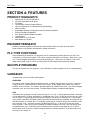
PRODUCT HIGHLIGHTS
•
•
•
•
•
•
•
•
•
•
•
•
Speeds from 0.1 Hz to 2,500,000 Hz
24 Inputs Expandable to 96 Inputs
24 Outputs
16,000 Bytes of Stored Program Memory
Up to 4 Programs can run Simultaneously (Multitasking)
Math Functions
Expandable Modules including Inputs and Thumbwheel Switches
Encoder Feedback Capabilities
Free Windows Based Software Included
Limit Switches
Addressable for up to 30 Axes
Baud Rates up to 38,400
ENCODER FEEDBACK
Enhanced encoder feedback commands have been added to allow full control of the encoders.
Refer to Section 8 on Encoder Commands for further instructions.
PLC TYPE FUNCTIONS
In the multitasking environment, four programs can run simultaneously which gives the unit a PLC like
functionality. For instance, Program 1 can contain a program that will turn-on Output 1 when Input 1 goes
Low. This will happen independent of everything else going on. This function is similar to a run on the
ladder using Ladder Logic on a PLC, and is not found in most sequential programming systems.
MULTIPLE PROGRAMS
The unit can contain up to four programs. Any combination of these programs can be run simultaneously.
VARIABLES
Variables exist in the form of Bits and Registers.
REGISTERS
The Indexer uses a register based command structure. A register may be written to or read. A register is
simply a name for a spot where some value is to be stored. Every register has a default value, can be
modified, and can be read. For instance, the Base Speed has a default value of 99. This can be changed
to another value, and it can also be read. The Base Speed Register is called the MB Register.
BITS
A Bit differs from a register in that its’ value may only be a 1 or a 0. In the programming world, a bit being
0 is considered OFF, or False; a bit being 1 is considered ON, or True. All bits can be read, but only some
can be written to. The Moving Bit can be read, but writing to that Bit has no meaning, so it is not allowed.
In this section, each Bit is described in detail. Some Bits will be affected by commands, and others will not.
Bits tell the status of a certain item. For example, the Moving Bit, or MV Bit will give the information if the
axis is moving or not. If the axis is moving, the Bit Value will be a 1. If the axis is not moving, the Bit
Value will be a 0. Bits are very useful in making information available to the user. Bits can also be used
to make decisions, like - If the Moving Bit is ON then activate output #1 which might turn on an LED to
show that the motor is moving. Another example would be a conditional branch - If the Moving Bit is ON
then loop to line number 10.
18
SECTION 4
FEATURES
MOTOR INPUT BITS
HOME TYPE BIT
This BIT sets the type of homing to execute when the HOME(+) command is issued.
HARD LIMIT INPUT BIT
This BIT indicates whether the HARD LIMIT input is on or off.
HOME LIMIT INPUT BIT
This BIT indicates whether the HOME LIMIT input is on or off.
SOFT LIMIT INPUT BIT
This BIT indicates whether the SOFT LIMIT input is on or off.
MOTION STATUS BITS
MOVING BIT
This BIT indicates whether the motor is moving or stopped, thus it is an output and cannot be
written to. A logic “1” indicates the motor is moving.
MOTION COMPLETE BIT
Reading this BIT will indicate whether the specified motor has completed its’ motion. A logic “1”
indicates that the motor has completed it’s move.
MOTOR DIRECTION BIT
The DIRECTION BIT will indicate which direction the motor is moving in. A logic “1” indicates that
the motor/axis in moving in the clockwise direction.
MOTOR ERROR CODE BIT
This Bit is enabled if the unit gets a motor error.
AT BASE SPEED BIT
This BIT is read as a 1 whenever the motor/axis is moving at the designated base speed.
AT SPEED BIT
The AT SPEED BIT indicates when the motor is moving at maximum speed.
AT RAMPING DOWN BIT
This BIT is read as 1 whenever the motor/axis is ramping down (decelerating).
AT RAMPING UP BIT
This BIT is read as a 1 whenever the motor/axis is ramping up (accelerating).
AT FAST JOG BIT
This BIT will be read as a 1 if the axis has been put into a fast jog cycle.
AT SLOW JOG BIT
This BIT will be read as a 1 if the axis has been put into a slow jog cycle.
AT RETRY BIT
This BIT will be read as a 1 if the indexer is still retrying to correct for encoder/motor difference.
19
SECTION 4
FEATURES
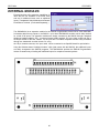
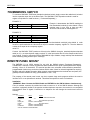
EXTERNAL MODULES
External Modules offer expansion capabilities for
items that are not available in the Driver Pack
and are for additional items such as additional
Inputs, Thumbwheel Switch Modules and Remote
Panel Mount Terminal. ( Purchased Separately )
The SMC40M-24I is an expansion module for the SMC40 Programmable Indexer series. Each SMC40M24I module adds 24 more inputs to the SMC40 - up to three SMC40M-24I modules can be daisy chained
for a total of 96 inputs. The expansion modules are simply connected to the SMC40 through a standard
telephone handset cable(on JP2) - no external power supply required. JP1 is the Input socket and JP2 is
the Output socket for the next module. All 24 inputs are TTL/CMOS compatible and are easily accessible
through two detachable terminal blocks. Or using
the 50 pin header connector, the input cable can be connected to an Opto22® board for opto-isolation.
Using the Windows based “Intelligent Indexer” utility (that comes with the SMC40), the additional inputs
are easily incorporated into SMC40 programs. The SMC40M-24I provides the SMC40 Programmable
Indexer a versatile way of dealing with additional inputs for complex automated systems.
SMC40M-24I
20
SECTION 4
FEATURES
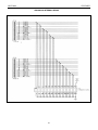
SMC40M-24I INTERNAL WIRING
21
SECTION 4
FEATURES
THUMBWHEEL SWITCH
To connect a SMC40M -TWS7seven decade thumbwheel switch, simply connect the cable that is included
into the expansion input slot on the Driver Pack. The SMC40M -TWS7 expansion module is used for
register manipulation or math functions. ( Purchased Separately )
EXAMPLE 1:
Line
1
Command
XMN
Example 1 demonstrates the SMC40 reading the
first thumbwheel module(A) value dialed. If three
modules were in use, refer to them as A,B,C
where the furthest that is multidropped is C.
Parameter 1
TA
EXAMPLE 2:
Line Command
Parameter 1
1
Math
RR=TA
2
Math
R1=RR*400
3
Math
XMN=RR
8
Example 2 demonstrates the Result Register equal to first thumbwheel module(A) value dialed. A math
function is performed with the value and set equal to another temporary register R1. Then the distance
number is set equal to the temporary register
value R1.
Connect the SMC40M -TWS7 (maximum of three) to the SMC40 through a standard telephone handset
cable (on J2) - no external power supply required. J1 is the Input socket and J2 is the Output socket for the
next module. If used in conjunction with the SMC40M-24I Input Module, simply multidrop the thumbwheel
switch module(s) along with the input module(s).
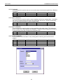
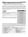
REMOTE PANEL MOUNT
The SMTNR2-1 is an ASCII terminal for use with the SMC40 Indexer (Purchased Separately).
TheSMTRN2-1 features a 20-key keypad with tactile feedback and a liquid crystal alphanumeric display
showing 4 lines of 20 characters. The terminal provides user selectable communications parameters,
programmable function keys, and other features which make it ideal for industrial applications requiring
flexibility and solid, reliable operation. When properly mounted between the terminal face and panel, the
gasket provides a NEMA 4/12 rating. (Dimensions4.9 x 4.9 x 1.43)
The purpose of the remote panel mount can be to operate large scale programs without the need to
introduce a PC or an alphanumeric terminal. This allows the operator to enter run time data.
Installation
(WARNING: Never Connect the RS232 Cable and SMTNR2-1to the SMC40 Indexer simultaneously.
A six pin modular connector is provided and used to connect to J1 of the SMC40 Indexer. Although this
connector is physically similar to the popular modular telephone connector, the terminal is not compatible
with telephone lines or signals. Connection to a telephone line will damage the terminal and voids the
warranty.
Settings
Parameters
Baud
Data Bits 8
Parity
Display PE
Repeat
Echo
Handshake
Self Test Disabled
Preset
9600
Options
300-600-1200-2400-4800-9600
7-8
None
Even-Odd-Mark-Space-None
Enabled Enable-Disabled
Fast
Slow-Fast-Disable
Disabled Enabled-Disabled
Enabled Enabled-Disabled
Enabled-Disabled
22
SECTION 5
INSTALLATION
SECTION 5 - INSTALLATION
UNIT SELECTION
Each SMC40 can be set to 1 of 10 possible unit numbers. This can be changed by turning the unit
address switch to the appropriate position. Refer to Section 2, Figure 1 for location assistance.
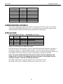
BAUD RATE SELECTION
The Baud Rate is the transfer rate of the serial communications. This is how fast the ASCII Data is sent
over the transfer lines. The number specifies the number of bits that are sent per second. With a baud
rate of 9600, 9600 bits of information are sent in one second. For standard communications (like the
SMC40), there is one start bit, one stop bit, and 8 data bits. This means that for every ASCII Character 10
bits are sent, so for the 9600 Baud Rate, 960 ASCII Characters will be sent every second. The Baud Rate
is selected by adjusting the Baud Rate Rotary Switch. This switch not only determines the baud rate, but
also sets the parameter RTS, for communication with your computer. Table 6 shows the position of the
switch for the corresponding baud rates. If you are not sure if your computer uses RTS, select RTS ON.
Most computers will work with either RTS ON or OFF.
Baud Rate - the baud rate is set externally by a rotary switch.
BAUD RATE
SWITCH POSITION
RTS ON
50
0
300
1
1200
2
2400
3
4800
4
9600
5
19200
6
38400
7
TABLE 5: Baud Rate Switch
RTS OFF
8
9
A
B
C
D
E
F
INSTALLATION – MOUNTING OPTIONS
When installing the Driver Pack, make sure there is adequate space for ventilation. Airflow is necessary
to maintain normal operating temperatures for the electronics inside. The Driver Pack should never reach
a temperature over 60 degrees Celsius. Do not block or cover the vents on the Driver Pack. Two different
methods of fastening the Driver Pack are available: bottom and top mounting.
Bottom Mount:
3
The Driver Pack can be fastened from behind the mounting surface by using four #10-32 x /8" screws.
Top Mount:
The Driver Pack has mounting flanges on the left and right sides which permits fastening from the top.
Each flange consist of two slots and a hole. All four slots can be used to mount the Driver Pack from the
front. For easy access mounting, use two slots on one side to slide the Driver Pack into place and then
secure it using the hole on the opposite side.
23
SECTION 5
INSTALLATION
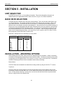
DIMENSIONS - DRIVER PACKS
INDEXER TERMINAL BLOCK AND SWITCH LOCATION
24
SECTION 5
INSTALLATION
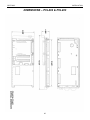
DIMENSIONS – PCL402 & PCL403
25
SECTION 5
INSTALLATION
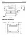
DIMENSIONS - SMC40M - TWS7
DIMENSIONS - SMC40M - 24I
26
SECTION 5
INSTALLATION
AC POWER CONNECTION AND FUSE
The fuse is located in a panel underneath the 115 VAC line cord
socket. See Section 9, on page 44 Specifications, for the
recommended part number.
Figure 3
HOOKUP FOR X250 VERSION
27
SECTION 5
INSTALLATION
SINGLE AXIS INDEXER CONNECTIONS
Pin #
Description
1
+5 VDC
2
Encoder X: Channel A
3
Encoder X: Channel B
4
Encoder X: Channel Z/Marker/Index
5
0 VDC
6
X: Hard7
X: Soft
8
X: Home
9
X: Hard+
10
0 VDC
11
X: CLK (Available on PCL401 ONLY)
12
X: DIR (Available on PCL401 ONLY)
13
X: PWR (Available on PCL401 ONLY)
14
0 VDC (Available on PCL401 ONLY)
Table 6: Connector TB2 Pinout
Pin # Description Pin # Description
1
Input #1
10
0 VDC
2
Input #2
11
+5 VDC
3
Input #3
12
Clamp
4
Input #4
13
Output #2
5
0 VDC
14
Output #3
6
Input #5
15
Output #4
7
Input #6
16
Output #5
8
Input #7
17
0 VDC
9
Input #8
Table 7: Connector TB3 Pinout
Note: Both the Input and Output 50PIN Headers require a flat ribbon cable and the 50PIN
Breakout Boards if all the I/O is required. The Anaheim Automation Catalog describes all
SMC40 Accessories.
Single Axis DPD72401 Connectors
1 - 7 Amp Bilevel Driver
Single Axis DPD60401 Connectors
1 - 6 Amp Microstep Driver
28
SECTION 5
INSTALLATION
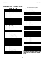
PCL INDEXER CONNECTIONS
AXIS X, Y, Z
Pin #
1
2
3
4
5
6
7
8
9
10
11
12
13
14
Description
ISO +5 VDC
Encoder X: Channel A
Encoder X: Channel B
Encoder X: Channel Z/ Marker/ Index
ISO 0 VDC
X: HardX: Soft
X: Home
X: Hard+
ISO 0 VDC
X: CLOCK OUTPUT
X: DIRECTION OUTPUT
X: POWER (ON / OFF)
X: 0VDC
Pin #
1
2
3
4
5
6
7
8
9
10
11
12
13
14
Description
ISO +5 VDC
Encoder Y: Channel A
Encoder Y: Channel B
Encoder Y: Channel Z/ Marker/ Index
ISO 0 VDC
Y: HardY: Soft
Y: Home
Y: Hard+
ISO 0 VDC
Y: CLOCK OUTPUT
Y: DIRECTION OUTPUT
Y: POWER (ON / OFF)
Y: 0VDC
Pin #
1
2
3
4
5
6
7
8
9
10
11
12
13
14
Description
ISO +5 VDC
Encoder Z: Channel A
Encoder Z: Channel B
Encoder Z: Channel Z/ Marker/ Index
ISO 0 VDC
Z: HardZ: Soft
Z: Home
Z: Hard+
ISO 0 VDC
Z: CLOCK OUTPUT
Z: DIRECTION OUTPUT
Z: POWER (ON / OFF)
Z: 0VDC
POWER CONNECTOR
Pin #
1
2
3
4
5
Description
9 –12 AC1
9 – 12 AC2
+12VDC UNREG
+5VDC REG
0VDC
I/O CONNECTOR
Pin #
1
2
3
4
5
6
7
8
9
10
11
12
13
14
15
IP 1 Connector Description
IN01/ HC /G1
IN02
IN03
IN04
ISO 0VDC
IN05
IN06
IN07
IN08
ISO 0VDC
IN09
IN10
IN11
IN12
ISO 0VDC
Pin #
1
2
3
4
5
6
7
8
9
10
11
12
IP 2 Connector Description
+5VDC
CLAMP
OUT01
OUT02
OUT03
OUT04
0 VDC
OUT05
OUT06
OUT07
OUT08
0VDC
ISO POWER CONNECTOR
Pin #
1
2
3
4
5
Description
O VDC
+5 VDC
+12 VDC UNREG
9 – 12 VAC
9 – 12 VAC
NOTE: The ISO Power Connector is
different from the Power Connector. Both
sides of the PCL402 & PCL403 will need
power.
29
SECTION 5
INSTALLATION
INDEXER INPUTS (FLAT RIBBON HEADER)
PIN #
Description
1
Input 1
2
0 VDC
3
Input 2
4
0 VDC
5
Input 3
6
0 VDC
7
Input 4
8
0 VDC
9
Input 5
10
0 VDC
11
Input 6
12
0 VDC
13
Input 7
14
0 VDC
15
Input 8
16
0 VDC
Table 8: Connector Pinout
PIN #
17
18
19
20
21
22
23
24
25
26
27
28
29
30
31
32
Description
Input 9
0 VDC
Input 10
0 VDC
Input 11
0 VDC
Input 12
0 VDC
Input 13
0 VDC
Input 14
0 VDC
Input 15
0 VDC
Input 16
0 VDC
PIN #
33
34
35
36
37
38
39
40
41
42
43
44
45
46
47
48
Description
Input 17
0 VDC
Input 18
0 VDC
Input 19
0 VDC
Input 20
0 VDC
Input 21
0 VDC
Input 22
0 VDC
Input 23
0 VDC
Input 24
0 VDC
INDEXER OUTPUTS (FLAT RIBBON HEADER)
PIN #
Description
1
Output 1
2
0 VDC
3
Output 2
4
0 VDC
5
Output 3
6
0 VDC
7
Output 4
8
0 VDC
9
Output 5
10
0 VDC
11
Output 6
12
0 VDC
13
Output 7
14
0 VDC
15
Output 8
16
0 VDC
Table 9: Connector Pinout
PIN #
17
18
19
20
21
22
23
24
25
26
27
28
29
30
31
32
Description
Output 9
0 VDC
Output 10
0 VDC
Output 11
0 VDC
Output 12
0 VDC
Output 13
0 VDC
Output 14
0 VDC
Output 15
0 VDC
Output 16
0 VDC
PIN #
33
34
35
36
37
38
39
40
41
42
43
44
45
46
47
48
Description
Output 17
0 VDC
Output 18
0 VDC
Output 19
0 VDC
Output 20
0 VDC
Output 21
0 VDC
Output 22
0 VDC
Output 23
0 VDC
Output 24
0 VDC
Note: Both the Input and Output 50PIN Headers require a flat ribbon cable and the 50PIN
Breakout Boards if all the I/O is required. The Anaheim Automation Catalog describes all
SMC40 Accessories.
30
SECTION 5
INSTALLATION
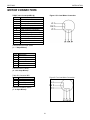
MOTOR CONNECTORS
TABLE 10A: Connector MB1 (2)
Pin #
1
2
3
4
5
6
7
8
9
10
11
12
13
Figure 4: Six Lead Motor Connection
Description
Phase 1
Phase 3
Common Phase 1 & 3
Reset Fault Input
Direction (internally connected)
Clock (internally connected)
0 VDC
On/Off (internally connected)
Halfstep/ Fullstep
No Connection
Common Phase 2 & 4
Phase 2
Phase 4
Pinout for BLD72 Driver Series
(1 – 7 Amps Bilevel)
Pin #
1
2
3
4
5
6
Description
Phase 1
Phase 3
Common Phase 1 & 3
Common Phase 2 & 4
Phase 2
Phase 4
Pinout for DPF11 Series
(2 - 12.5 Amps Bilevel)
Table 2D: Connector MB1
Pin #
Description
1
Phase 1 A
2
Phase 3 /A
3
Phase 2 B
4
Phase 4 /B
Figure 5: Four Lead Motor Connection
Pinout for DPD60401 Series
(1 - 6 Amps Bilevel)
31
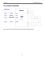
SECTION 6
COMMUNICATIONS
PCL HOOKUP DIAGRAM
Note: Contact the factory direct if you have questions regarding the hookup procedures.
32
SECTION 6
COMMUNICATIONS
SECTION 6 - COMMUNICATIONS
TALKING TO THE INDEXER
Anaheim Automation’s SMC40 Programmable Indexers communicate by using the RS232C or RS422
standards. Most computers contain at least one RS232 serial port. Some industrial computers have a
RS422 serial port. To communicate with the SMC40, use connector P1. P1 is used for either R3232 or
RS422, and is set by sliding the two switches to the appropriate direction. P1 is a DB9 Female. To
communicate with subsequent axes, use P2, the RS422 output port. P2 is a DB9 Male, and is always set
for RS422, regardless of the switch setting for P1. The switches affect only the Input Port P1. The
difference between the two types of communications is discussed below.
RS232
This serial communication mode is single ended. This means that for each signal there is one wire, and a
common ground reference used by all the signals. For the four signals, RD, TD, CTS and RTS to be
transmitted, RS232C requires five wires. The signal line maintains levels of +5VDC to +15VDC (LOW
LOGIC INPUT) and -5VDC to -15VDC (HIGH LOGIC INPUT). The receiver for the RS232 looks for a
voltage potential of +3 to +25 volts for a logic LOW, and -3 to -25 volts for a logic HIGH. For a valid logic
level, the voltage must be +/-3 volts. RS232 works well at 9,600 baud over distances of up to 50 feet
maximum. RS232 is susceptible to electrical noise, and should not be used in noisy areas. Always use
the shortest cable connection possible.
Note: Keep control wiring separated from motor cable/wiring.
RS422
To talk to the SMC40 in RS422 set the switch to RS422, and use P2. The RS422 serial communication
standard is differential. This means that from each signal, there are two wires. For the four signals
transmitted there needs to be nine wires including the ground reference. The signal line maintains a
voltage level of up to +12 volts on either line. The polarity of the line switches is used to obtain the logic
levels. For example, if RD+ is more positive than RD- then it is a logic HIGH. If RD- is more positive than
RD+, then it is a logic LOW. For a valid logic level, the voltage difference between RD+ and RD- needs to
be greater than 200 millivolts. RS422 is unsusceptible to noise due to the differential lines. RS422 is
specified at a maximum of 9600 Baud at up to 4000 feet.
RS232C
FUNCTION
25 PIN CONNECTOR
1
CG
2
TD
3
RD
4
RTS
5
CTS
7
O VDC
TABLE 12: RS422 Connector Pinout
RS232 FUNCTION
Chassis Ground
Transmit Data
Receive Data
RTS - Request To Send
CTS - Clear To Send
SG - Signal Ground
33
SECTION 6
RS422
FUNCTION
9 Pin Connector
1
SG
2
CTS+
3
CTS4
TD+
5
TD6
RTS+
7
RTS8
RD+
9
RDTABLE 13: RS422 Connector Pinout
COMMUNICATIONS
DESCRIPTION
signal ground
clear to send
clear to sendtransmit data+
transmit datarequest to send+
request to sendreceive data+
receive data-
HANDSHAKING SIGNALS
There are two "handshaking" signals: RTS (Request to Send) and CTS (Clear to Send). Some devices
use these handshaking signals and others do not. It is important to know if your device supports certain
handshake signals. Anaheim Automation Indexers support both of these signals.
DTE VS DCE
(THE COMPUTER IS THE DTE......THE INDEXER IS THE DCE)
Signal
9 PIN
DIRECTION FUNCTION
Connector
SG
5
0 VDC
Signal Ground
TD
3
DTE to DCE transmitted data
RD
2
DCE to DTE received data
RTS
7
DTE to DCE request to send (DTE ready)
CTS
8
DCE to DTE clear to send (DCE ready)
TABLE 14: Pin Description for RS232 with a DB9
There are two types of devices defined. The first is called DTE (data terminal equipment). Examples of
this would be a terminal, or an IBM Compatible Computer. The second type of device is a DCE (data
communication equipment). Examples of this would be a modem or an Anaheim Automation Indexer such
as the SMC40. DTE's have input pins of one type corresponding to output pins on the DCE's.
NOTE: THE SIGNAL NAMES ARE FROM THE POINT OF VIEW OF THE DTE COMPUTER. FOR
EXAMPLE, PIN 3 IS CALLED TD (TRANSMIT DATA) BY BOTH SIDES, EVEN THOUGH THE DTE
(COMPUTER) SENDS IT AND THE DCE (SMC40) RECEIVES IT.
With a DB9, a DTE (such as a computer) transmits on pin 3 and receives on pin 2.
With a DB9, a DCE (such as a SMC40) transmits on pin 2 and receives on pin 3.
34
SECTION 6
COMMUNICATIONS
“A MANNER OF SPEAKING”
The communication signals supported by Anaheim Automation Indexers are: RECEIVE, TRANSMIT,
CLEAR TO SEND (BUSY), AND REQUEST TO SEND.
The method in which the Computer and the Indexer communicate is as follows: When the computer wants
to send some information, it looks at the CTS (Clear To Send) line. This will inform the computer if the
Indexer is ready to receive information. If a logic LOW is read (meaning it is clear to send), the computer
will send information on pin 3, in which the Indexer will receive on pin 3.
When the Indexer receives data that requires some computational time, it will pull the CTS HIGH meaning
it is not clear to send data.
When the Indexer is ready to send something to the Computer it looks at the RTS signal which will inform
the Indexer that the Computer is busy. If the RTS is low then the Indexer will send information on pin 2,
which will be received by the Computer on pin 2 also.
RTS DEFINED
On the SMC40, there is an option to either enable, or disable the RTS. If RTS is enabled, then the above
description applies. If RTS is disabled, then when the SMC40 wants to send information to the Computer,
it will send it without looking at the RTS line. This is used when the computer does not support the RTS
line.
CTS DEFINED
The CTS line must always be supported. No information should be sent to any indexer unless the CTS
line is low. Otherwise the data sent may be lost, and the indexer could possibly stop communicating.
NOTE: THE SIGNAL NAMES ONLY MAKE SENSE FROM THE POINT OF VIEW OF THE DTE. FOR
EXAMPLE, PIN 3 IS CALLED TD (TRANSMIT DATA) BY BOTH SIDES, EVEN THOUGH THE DTE
SENDS IT AND THE DCE RECEIVES IT.
Pin #
Name
Description
1
CG
Chassis Ground
2
TD
Transmit Data
3
RD
Receive Data
4
RTS
Request To Send
5
CTS
Clear To Send
7
0 VDC
Signal Ground
TABLE 15: RS232C 25 Pin Connection (computer port)
35
SECTION 7
INTELLIGENT SOFTWARE
SECTION 7-INTELLIGENT SOFTWARE
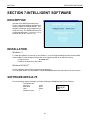
DESCRIPTION
Included with a SMC40 purchase Driver
Pack is a Windows software package that is
used to program the SMC40 indexer. This
software will allow for easy programming of
the Driver Pack. The SMC40 software runs
on Microsoft Windows 3.1 (Version 1.12) or
Windows 95/ 98/ NT (Version 1.13).
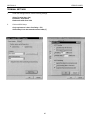
INSTALLATION
Windows 3.1
To install the software you need to go into Windows. From the Program Manager select the menu File,
and then Run. Put the Intelligent Indexer Disk in the appropriate disk drive and select Setup.
It might look like:
A:\setup .exe
Follow the instructions on the screen.
Windows 95/ 98/ NT
Put the Intelligent Indexer Disk in the appropriate disk drive.
Go to the Start Button, and Select Run. Choose A:\setup.exe and follow the instructions on the screen.
SOFTWARE DEFAULTS
Run the Intelligent Indexer Software by Double Clicking the SMC40 Program File in Windows.
The Defaults are:
Com Port
Com1
Baud Rate
9600
Units
Steps
Number of Axes
1
36
SECTION 7
INTELLIGENT SOFTWARE
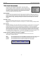
THE FOUR PROGRAMS
There are four different program areas available. These are the Main
Program, Program 1, Program 2, and Program 3. When running the Driver
Pack, these programs can run simultaneously. They have access to the same
set of registers, and can affect the other program with some of the appropriate
commands. This allows a programmer to write sophisticated routines that
would not be possible with other similar products.
MAIN PROGRAM
This is area where most programs will reside. When a program is started by the Menu Item START, or
powered up after setting the Autostart Flag, the Main Program will start running. At this point, the other 3
program areas will be idle. There are commands that can start the other three programs. The program
can be 1000 lines or longer, depending on the type of commands used and the space used in the other
programs.
PROGRAM 1, 2 and 3
These are the secondary programs that will run concurrently with the Main Program.
The user must enter a Branch Quit statement in all Programs 1,2, & 3 before sending/ compiling the Main
Program.
MULTITASKING
The word multitasking in this context means that four programs can run at the same time. This use of the
multitasking environment will allow PLC-like functions to be programmed into this unit. One example
would be to turn an output on for one second whenever an input goes on. To do this with standard
sequential programming, the programmer would constantly have to check for that input, while the program
is still doing all that it has to do as well. This can often overburden the program so that another module
has to be purchased to do that function. With the multiple programs available in this unit, it is like having
four separate modules all wrapped up into 1. With this unit, that program can be put into Program 1, 2, or
3. This off-loads the Main Program from having to continuously check for that condition.
ADDING, INSERTING, CHANGING OR DELETING A COMMAND
To add a command to the program, select the appropriate choice from the main screen –
ADD, INSERT, CHANGE or DELETE.
ADD:
INSERT:
CHANGE:
DELETE:
This command allows the user to place additional commands at the bottom of the program.
This command allows the user to insert additional commands at the cursor location.
This command allows the user to change commands at the cursor location.
This command allows the user to delete commands at the cursor location.
37
SECTION 7
INTELLIGENT SOFTWARE
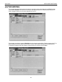
AUTOSTARTING
The programs that have been tested and ready for execution can be downloaded to the SMC40 Indexer
and Autostart Enabled. This feature will now allow the SMC40 Indexer to be disconnected from the PC
and the program stored can now start independent of the PC.
The program can also be Autostart Disabled when the program needs editing. Please reconnect the PC to
SMC40 Indexer and note that the check mark to the left of the Disable Command of the SMC40 Menu
Commands will appear when the Disable Command has been clicked/ selected twice.
38
SECTION 8
COMMAND DESCRIPTIONS
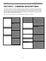
SECTION 8 - COMMAND DESCRIPTIONS
This section covers the broad range of commands available in the SMC40. Commands are grouped together with
other similar Commands. They include Branching, Start/Stop, Motion Parameters, Outputs, User Entry, Encoder
Commands, Math, Terminal Commands, Jog Inputs and Program 1,2,3. After clicking the Insert, Add or Change
Button, the Select a Command screen comes up to select commands. Select the Button of your choice and it will
offer you a selection of commands from that group.
Below is a list of Command Groups, and the commands that correspond to those groups.
Outputs
Branching
Label
Goto
If (bit) Then
If (Reg) Then
Gosub
Return
Quit
Wait Delay
For Loop
Set Outputs
User Entry
User Entry
Encoder Commands
Encoder Position
Encoder Autocorrection
Encoder Delay
Encoder Retries
Encoder Window
Encoder Motor Ratio
Start/Stop
Go Absolute
Go Relative
Home
Slew
Stop Hard
Stop Hard
Wait Motor
Math
+ Addition of Registers
- Subtraction of Registers
/ Division of Registers
* Multiplication of Registers
Terminal Commands
Write Text
Write Value
Write ASCII
Write Value
Motion Parameters
Base Speed
Current Hold
Dir+
DirMax Speed
Position
Accel/ Decel
Speed Limit
Slow Jog Speed
Fast Jog Speed
Jog Inputs
Jog+
JogFast Jog
Program 1,2,3
Start Program 1
Start Program 2
Start Program 3
Stop Program 1
Stop Program 2
Stop Program 3
39
SECTION 8
COMMAND DESCRIPTIONS
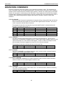
BRANCHING COMMANDS
Branching Commands cause the program to go to a specific line number or label. This sometimes will
occur if a condition exists, like an input being activated. The most common use will be to have a machine
operator activate a switch before the machine begins operation. Another use of these types of commands
would be for a program to continuously go from the bottom of the program back to the top of the program.
The Branching Commands cause the program to ‘branch’ to another part of the program based on a set of
conditions, like a switch being pressed, a register value equal to a number, a bit set, or many other
conditions.
GOSUB COMMAND
When the Gosub Command is implemented, the program will go to the specified line and then the
Return Command will send it back to the line below the original Gosub Command. This must be
used in conjunction with the Return Command.
This sample will cause the next instruction to go to the label Function 2, execute the lines 68
through 74, and then return to line 15..
Line
Command
Parameter 1
Parameter 2
Comments
14
Gosub
FUNCTION2
*
67
Label
FUNCTION2
*
75
Return
Returns to Line 15
GOTO COMMAND
The Goto Command causes the program to go directly to the specified line. This line can be
described by a Line Number, a Register Value, or a Label. When using a Register Value, you must
make sure that there is a value stored in that Register. If there is a value, for example 10, then
this command will cause the program to jump to line 10 for the next command.
This sample will cause the next instruction to go to the Label Top.
Line
Command
Parameter 1
Parameter 2
14
Goto
TOP
Comments
IF BIT COMMAND
The IF BIT COMMAND is a conditional statement used to execute another command based on
whether or not a certain Input condition is met.
Line
Command
Parameter 1
Parameter 2
Comments
1
If I1 = 0
Then TOP
Else CONTINUE
IF REGISTER COMMAND
The IF REGISTER COMMAND is a conditional statement used to execute another command
based on whether or not a certain Register condition is met.
Line
1
Command
If R1 = 0
Parameter 1
Then TOP
Parameter 2
Else CONTINUE
Comments
LABEL COMMAND
The LABEL command is simply used to label a line. As mentioned before, labels are commonly
used with branching statements.
Line
Command
Parameter 1
Parameter 2
Comments
1
Label
TOP
40
SECTION 8
COMMAND DESCRIPTIONS
BRANCH QUIT COMMAND
The BRANCH QUIT command will cause the program to stop execution of the associated program
(Main Program, Program 1, 2, or 3).
Line
Command
Parameter 1
Parameter 2
Comments
1
Branch Quit
RETURN COMMAND
The Return Command will cause the program to return to the line below the last Gosub Command
that was issued. The return command must be used in conjunction with the Gosub Command or
an error will occur.
Line
Command
Parameter 1
Parameter 2
Comments
1
Return
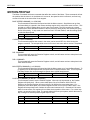
WAIT DELAY COMMAND
This Command sets the Delay Register, and waits for the time specified to expire before
continuing to the next line in the program. The Value is in 1/1000 of a second, meaning that a
value of 1000 is 1 seconds. The below example would begin moving 1000 steps. After the start
of the motion, 1 seconds would need to expire before the output is turned on. Value(s) of 1 60000 equivalent to .001seconds - 60seconds is the usable delay range per line.
Line
1
2
3
Command
Go Relative
Wait Delay
Set Outputs
Parameter 1
1000
1000
ON:1,
Parameter 2
Comments
FOR LOOP
The For Loop Command is separated into two sections where the Top Loop Identifies the top
section of the looping command for a pre-selected number of times.
Line
Command
Parameter 1
Parameter 2
Comments
1
Loop Top Start
4 Times
The Bottom Loop Identifies the bottom section of the looping command in order to close the loop.
Line
Command
Parameter 1
Parameter 2
Comments
10
Loop Bottom Start
41
SECTION 8
COMMAND DESCRIPTIONS
START/ STOP COMMANDS
This grouping of command pertains to functions that will Start and Stop the Motion. All axis
motion begins at the specified Base Speed and then ramps up to Max Speed. If the motion is
definite, the axis will then ramp from Max Speed down to Base Speed to complete the move.
Setting Motor Base, Max, and Ramping Speeds is discussed in the Motor Parameter Command
Section.
GO ABSOLUTE COMMAND
This Command is a move-to-position command meaning that it will move to the position specified.
For instance, in the below example it will cause the motor to go to position 0. If the Motor Position
is at 2500, the Go Absolute Command of 0 will move to the position and the Direction Register
would be 0 (CCW Direction).
Line
Command
Parameter 1
Parameter 2
Comments
1
X Go Absolute
0
GO RELATIVE COMMAND
This Command is a move-a-distance command meaning that it will move the distance set in the
Go Relative Command. For instance, in the example below it will cause the motor to go 1000
steps in the CCW direction
Line
Command
Parameter 1
Parameter 2
Comments
1
X Dir 2
X Go Relative
1000
HOME COMMAND
This Command will cause the motor to move continuously in the direction specified by a Direction
Command until a Home limit switch is hit. (Refer to the HOME TYPE COMMAND for Home Types
available.)
Line
Command
Parameter 1
Parameter 2
Comments
1
X Dir 2
X Home
0
HOME TYPE COMMAND
This Command specifies the type of Homing that will be executed when a Home Command is
executed. There are 3 types of Homing.
Home Type 0
This will rotate continuously in the appropriate direction and speed until a Soft
Limit Switch is active. It will then Ramp Down to Base Speed, and then Stop
when the Home Limit Switch is active.
Home Type 1
This will rotate continuously in the appropriate direction and speed until a Home
Limit Switch is active. It will then Ramp Down to Base Speed, Stop and instantly
reverse direction. It will then continue in this reversed direction and then Stop
when the Home Limit Switch is once again inactive. This will stop on the ‘negative
edge’ of the switch only, so the switch can be passed on ramp down and then hit
again in the reverse direction stopping after it comes off the switch. This is most
useful for taking backlash out of a leadscrew.
Home Type 2
This will rotate continuously in the appropriate direction and at Base Speed until a
Marker Pulse is active. This is typically called Channel Z from an encoder.
Although the intent of this Homing is for use with an encoder, it is not limited by it.
A simple switch will work as well.
42
SECTION 8
COMMAND DESCRIPTIONS
SLEW COMMAND
This Command will cause the motor to move continuously in the direction specified by a Direction
Command.
Line
Command
Parameter 1
Parameter 2
Comments
1
X Dir 2
X Slew
STOP HARD COMMAND
This Command will cause the motion to stop immediately without any ramping down. If the Motor
was moving at speeds higher than what it can reliably start and stop at, it is likely that the Motor
will not be at the position that the Position Register reads.
Command
Parameter 1
Parameter 2
Comments
1
X Stop Hard
STOP SOFT COMMAND
This Command will cause the motion to stop immediately after ramping down. This causes the
Motor to ramp down to Base Speed before stopping. This gentler way of stopping is not likely to
cause positioning errors like the Stop Hard Command would.
Command
Parameter 1
Parameter 2
Comments
1
X Stop Soft
WAIT MOTOR COMMAND
This Command waits for the Motor to stop moving before continuing to the next line in the
program.
Line
1
2
3
Command
Go Relative
Wait Motor
Set Outputs
Parameter 1
1000
ON:1,
43
Parameter 2
Comments
SECTION 8
COMMAND DESCRIPTIONS
MOTION PROFILE
The Motor Commands are those commands that affect the motion of the Motor. These commands will set
the position that the motor is at, the distance it is to travel, the speed at which it will travel, and how long
current will remain in the motor after it has stopped.
BASE SPEED COMMAND (1 to 2,500,000)
This Command will determine the speed at which the Motor starts at. Step Motors can go from
rest immediately to a speed in the motors start/stop region which varies from motor to motor. This
is similar to a Ski-Lift taking skiers up to the top of a mountain. The lift is traveling at a certain
speed and the skiers attach themselves to the lift (usually by sitting down) and instantly are going
the Ski-Lifts velocity. A step motor can start from rest in a similar fashion, and this starting speed
is called the Base Speed.
Line
Command
Parameter 1
Parameter 2
Comments
1
X Base Speed
500
CURRENT HOLD COMMAND
This Command specifies that current in the motor can be turned OFF=0 or ON=1 during the
program execution. The example holds current off in the X-axis motor after a motion is completed.
Line
Command
X Current Hold
Parameter 1
0
Parameter 2
Comments
DIR- COMMAND
This command will cause the Direction Register to be 0, and will cause motion to take place in the
Counter Clock Wise Direction.
DIR+ COMMAND
This command will cause the Direction Register to be 0, and will cause motion to take place in the
Clock Wise Direction.
MAX SPEED COMMAND (1 to 2,500,000)
This Command will determine the speed at which the Motor ramps up to from the Base Speed. To
go speeds over 20,000 steps/second, the Speed Limit Command must be used. This is to protect
Half-Step Drivers that can be damaged at speeds above 40,000 steps/second.
Line
Command
Parameter 1
Parameter 2
Comments
1
X Max Speed
POSITION COMMAND (-8,388,607 - +8,388,608)
This Command is used to set the Position Register. When the unit is powered up, the Position
Register will initially be 0. When a move takes place, like a Go Relative 1000 in the CW
Direction, the Position Register will count up from 0 to 1000 as the move takes place. If a
subsequent move takes place, the Position Register will then count up from 1000 to 2000. This
Register will always keep track of where the motor was instructed to be. Remember if the motor
stalls for some reason, this register will not reflect the true position of the motor. For a close loop
system, an encoder must be used. The sample below will home your system, wait for the motor to
stop running then sets the position register equal to zero.
Line
1
2
3
Command
X Home
Wait Motor
X Postion
Parameter 1
1
0
44
Parameter 2
Comments
SECTION 8
COMMAND DESCRIPTIONS
ACCEL/DECEL COMMAND( 1 - 1,000,000 )
This defines the acceleration/deceleration (or ramping) of the motor.
Line
1
Command
X Accel/Decel
Parameter 1
500
Parameter 2
Comments
SPEED LIMIT COMMAND
This Command sets the limit for the Base Speed and the Max Speed. The Default value is
20,000. This should always be kept at the highest speed that the motor would ever be run at.
SLOW JOG SPEED COMMAND
This Command presets the Run Speed when the users sets the Slow Jog+ or Fast Jog- to 0VDC.
This function is usually used to manually position the motor.
FAST JOG SPEED COMMAND
This Command presets the Run Speed when the users sets the Fast Jog+ or Fast Jog- to 0VDC.
This function is usually used to manually position the motor.
45
SECTION 8
COMMAND DESCRIPTIONS
OUTPUT COMMANDS
SET OUTPUT COMMAND
This will Activate or Deactivate any of the 24 Outputs. Select only the Outputs that are going to
be changed, and leave the other Outputs as Don’t Cares(n/c). The SMC40 has 24 programmable
open-collector out puts. When an open-collector is set ON, the voltage reading is about 0.7Vdc.
When the output is set OFF, the reading is an OPEN. Note: Only five outputs can be turned on
per line. The following command line can be repeated to turn more than five outputs when
required.
Line
1
Command
Set Output
Parameter 1
ON:1,2,10,18
Parameter 2
OFF:5,6,12,20
Comments
In this example SET OUTPUT
sets outputs 1,2,10, and 18 ON.
On the same command line,
outputs 5, 6,12,and 20 are set
OFF. Note, that a SET
OUTPUT command might be
used with a conditional IF
Statement.
WARNING: Always use a Diode (Motorola 1N4002 or Equivalent) to clamp any Inductive Loads (Relays,
Solenoids, etc.) due to fly back voltages. Refer to Specifications for further information.
46
SECTION 8
COMMAND DESCRIPTIONS
USER ENTRY COMMANDS
USER ENTRY COMMAND
This Command allows any Commands to be entered that the Software does not directly support.
See the Direct Programming Guide discussed in this manual, and the SMC40.WRI Document on
the Intelligent Indexer Disk for more information.
Register Manipulation
The Read Value (RV) Register will read a value and temporarily store it. Note that any
register comparison that needs to be evaluated may need to be stored into a defined
Register (R1- R100) for the Single Axis SMC40’s and (R1-R200) for Dual & Triple
SmC40’s to avoid losing the stored number.
The “IF THEN” Command may compare Register to a known value without having to
reassign it but you may lose the RV Register value if any MATH or other Read Values
Commands are in your program.
Example: Load the register value RV into R1 and increment register R2 using Math
Equations.
Line
1
2
Command
User Entry
User Entry
Parameter 1
R1=RV
R2=R1+1
47
Parameter 2
Comments
SECTION 8
COMMAND DESCRIPTIONS
PROGRAM 1, 2, 3
Start Program 1, 2, 3
When the Menu Item Program Start is executed, it starts only the Main Program. To start
Program 1, the Command is XPA=1, to start Program 2, the Command is YPA=1, and to
start Program 3, the Command is ZPA=1.
Example: To Start Program 1
Line
1
Command
Start Program 1
Parameter 1
Parameter 2
Comments
Stop Program 1, 2, 3 (Stopping a Program)
When the Menu Item Program Start is executed, it starts only the Main Program. To stop
Program 1, the Command is XPA=0, to stop Program 2, the Command is YPA=0, and to
stop Program 3, the Command is ZPA=0.
Example: To start Program 1
Line
1
Command
Stop Program 1
Parameter 1
48
Parameter 2
Comments
SECTION 8
COMMAND DESCRIPTIONS
ENCODER COMMANDS
ENCODER AUTOCORRECT ( Enable/ Disable)
This Command will set the Encoder Autocorrection Bit. A 1 will cause the Autocorrection feature
to be enabled, and a 0 will cause it to be disabled. If the Autocorrection feature is enabled, after
the completion of a move, the Encoder Register will be verified to see if it is in the correct position.
If it is not, a correction move will be implemented. See Encoder Retries.
Note: Anytime the ER register, EP register, EW register, or the EM register is written to, the
Encoder Auto Correction feature is disabled to prevent spontaneous Motor Errors - hence it
will need to be re-enabled. Make sure to use the Encoder Auto Correction command as the
last encoder line command to avoid disabling.
Line
Command
Enc Auto
Parameter 1
1
Parameter 2
Comments
ENCODER DELAY
This Command will set the dwell time that the unit will wait before checking the Encoder Register,
after the end of the move. This will take out the ringing that might be associated with the
mechanics of the system. The range for this is between 1 and 1000 and is in 0.001 seconds [1000
is 1 second]. (Encoder Delay is used to allow for the motor settling time after a move.)
Note: Anytime the ER register is written to, the Encoder Stall Detection feature is disabled to
prevent spontaneous Motor Errors - hence it will need to be re-enabled.
Line
1
Command
Enc Delay
Parameter 1
500
Parameter 2
Comments
½second
ENCODER POSITION (EP)
This Command will set the starting point of the Encoder Position.
Note: Anytime the EP register is written to, the Stall Detection and Encoder Auto - Correction
features are disabled to prevent spontaneous Motor Errors - hence they will need to be re enabled.
Line
1
Command
Enc Position
Parameter 1
0
Parameter 2
Comments
Position 0 can be
the Home Position
ENCODER RETRIES (ER)
This Command will set the number of Encoder Retries or number of tries (0 - 250) when
autocorrecting.
Note: Anytime the ER register is written to, the Encoder AutoCorrection feature is disabled to
prevent spontaneous Motor Errors - hence it will need to be re - enabled.
Line
Command
Parameter 1
Parameter 2
Comments
1
Enc Retries
5
retry 5 times
49
SECTION 8
COMMAND DESCRIPTIONS
ENCODER RATIO (EM)
This Command will set the Ratio between the Motor and the Encoder. The ENCODER RATIO
register is the conversion factor from 1 motor step to 1 encoder quadrature pulse for the
associated indexer - this accounts for any gearing mechanism between the motor and the
encoder.
Note: Anytime the ENCODER RATIO (EM ) register is written to, the Encoder AutoCorrection
feature is disabled to prevent spontaneous Motor Errors - hence it will need to be re enabled.
{ Negative values represent when the encoder direction is opposite to the motors direction.}
Line
1
Command
Enc Ratio
Parameter 1
2.75
Parameter 2
Comments
ENCODER WINDOW (EW)
This Command will set the Encoder Window which allows the user to determine the number of
steps the motor can be off before correcting. ( 1- 1,677,215)
Example: The motor missed its stop position by 2 steps. This will mean if the user set the Encoder
Window to 3, the encoder will not correct its position.
Note: Anytime the ENCODER WINDOW (EW ) register is written to, the Encoder AutoCorrection
feature is disabled to prevent spontaneous Motor Errors - hence it will need to be re enabled.
Line
1
Command
Enc Window
Parameter 1
3
Parameter 2
Comments
NOTE: Any Advanced Programming questions should be discussed with the
factory direct.
50
SECTION 9
DIRECT PROGRAMMING
SECTION 9 – DIRECT PROGRAMMING
ALPHABETIC QUICK
REFERENCE LIST
COMMAND TYPE
COMMAND
DESCRIPTION
MOTION
PROFILE
MA
MB
MM
MS
MF
MJ
HT
DD+
MN
MP
GA
GH
GR
GS
HH+
SA
SH
SI
SL
SS
MC
MD
ME
MV
WM
AB
AD
AF
AJ
AM
AR
AS
AU
O
OE
Motor Accel/Decel [X/Y/Z]
Motor Base Speed [X/Y/Z]
Motor Max Speed [X/Y/Z]
Motor Speed Limit [X/Y/Z]
Motor Fast Jog Speed [X/Y/Z]
Motor Slow Jog Speed [X/Y/Z]
Home Type [X/Y/Z]
Motor Direction Motor Direction +
Motor Number [X/Y/Z]
Motor Position [X/Y/Z]
Go Absolute [X/Y/Z]
Go Home [X/Y/Z]
Go Relative [X/Y/Z]
Go Slew [X/Y/Z]
Hard- limit input [X/Y/Z]
Hard+ limit input [X/Y/Z]
Stop All Indexers
Stop Hard [X/Y/Z]
Soft Limit Input[X/Y/Z]
Soft Limits Enable [X/Y/Z]
Stop Soft[X/Y/Z]
Motion Complete [X/Y/Z]
Motor Direction [X/Y/Z]
Motor Error Code [X/Y/Z]
Moving [X/Y/Z]
Wait Motor [X/Y/Z]
At Base Speed Bit [X/Y/Z]
At ramping Down Bit [X/Y/Z]
At Fast Jog Bit [X/Y/Z]
At Slow Jog Bit [X/Y/Z]
At Maximum Speed Bit [X/Y/Z]
At auto-correct Retry Bit [X/Y/Z]
At Speed [X/Y/Z]
At ramping Up Bit [X/Y/Z]
Outputs (1-24)
Outputs External Module
(O25 - O48)
Output Register
Inputs (1-96)
Bi-directional Input/Output
(IO1- IO24)
Input Register (I1 -I24)
Input A module (I25 -I48)
Input B module (I49 -I72)
Input C module (I73 -I96)
Thumbwheel A Module
Thumbwheel B Module
Thumbwheel C Module
Program Autostart [X/Y/Z]
Program Insert [X/Y/Z]
Program Clear [X/Y/Z]
Program Delete [X/Y/Z]
Program Edit [X/Y/Z]
Program Memory available
Programs Quit All
START/STOP
MOTION
MOTION STATUS
INPUT/OUTPUT
OR
I
IO
EXPANSION
PROGRAMMING
IR
IA
IB
IC
TA
TB
TC
PA
PI
PC
PD
PE
PM
PQ
PR
PS
PT
NO
PP
PW
PL
PN
TERMINAL
BRANCHING
& LOOPING
REGISTERS
& BITS
MATH
51
PB
RK
RTS
RV
WK
WT
WV
CTS
BB
BE
BF
BG
BL
BQ
BR
BS
BT
FL
IF
B
R#
R
RS
B#
B?
BB%
B+
B*
GT
LT
RP
R/
R?
RF
RI
R+
R*
R%
RK
RN
RO
RRR
RT
RZ
EQ
Program Run [X/Y/Z]
Program Start [X/Y/Z]
Program Trace [X/Y/Z]
No Operation
Program Pause
Program Window Size
Program List [X/Y/Z]
Program Instruction Number
[X/Y/Z]
Program Brief Listing
Read Key From Terminal
RTS to Send
Read Value
Write Key
Write Text
Write Value
Clear To Send
Branch Breakpoint
Branch End of Program
Branch if False
Branch Goto
Branch Loop
Branch Quit
Branch Return
Branch Subroutine
Branch if True
For Loop
IF Condition
Bits (1-100)
Indirect Register
Registers (1-100)
Read Value Scale Factor
Indirect Bit
Pattern Match
result Bitwise NOT
result Bitwise XOR
result Bitwise OR
result Bitwise AND
Greater than Flag
Less than Flag
Positive Flag
Result Divide
Result compare
Result fraction
Result Integer
Result add
Result multiply
Result modulus
Read Key
Negative Flag
Overflow Flag
Result Subtract
Result Register
Square Root
Result Zero Flag
Equals Flag
SECTION 9
Miscellaneous
ENCODER
LIMIT INPUTS
DIRECT PROGRAMMING
VN
ID
HC
HP
MH
@
@.
#
!
AC
AE
AL
CR
DL
DP
EC
FD
JF
LB
WD
WR
WS
WW
JJ+
JF
FD
UP
LP
EA
ED
EM
EP
ER
EW
HH+
HI
SI
SL
Version Number
Identify
High speed counter
High Priority
Motor Hold Current [X/Y/Z]
unit select
unit select all
indirect register
Error
Auto Cursor
Auto Error
Auto Linefeed
Cold Reset
Delay
Decimal Place
Error Code
Full Duplex
Jog Fast Input bit/configuration
Label
Wait Delay [X/Y/Z]
Wait Read Value
Wait value Scale Factor
Wait Write
Jog- Input Configuration [X/Y/Z]
Jog+ Input Configuration [X/Y/Z]
Jog Fast Input configuration
[X/Y/Z]
Full Duplex
Unlock Program
Lock Program
Encoder Auto-correction [X/Y/Z]
Encoder Delay Register [X/Y/Z]
Encoder to Motor ratio [X/Y/Z]
Encoder Position [X/Y/Z]
Encoder Retries [X/Y/Z]
Encoder Window (autocorrection)
Hard - limit input
Hard + limit input
Home limit Input
Soft Limit Input
Soft Limits Enable
Note: Refer to Chapter 13 for Command Set
52
SECTION 9
DIRECT PROGRAMMING
TALKING WITH A TERMINAL (TT1R2-1)
WARNING: DO NOT CONNECT THE PC AND HANDHELD TO SMC40 AT THE SAME TIME.
DOWNLOAD PROGRAM AND THEN TEST WITH HANDHELD AFTER DISCONNECTING FROM PC.
Start Communications
Press CTRL and SHIFT simultaneously and while holding down on those two buttons press F1. This will
now display the terminal parameters. Press F2 to scroll through the parameters. Set the Address and the
Baud Rate on the SMC40 Indexer switches first (Pg 24), then set the Baud Rate on the Terminal. Press F1
to scroll through the different settings available. The SMC40 Indexer will communicate by sending the
characters back, so be sure to have the Terminal with the Echo = Disable set.. Data Bit = 7, Parity =
Space, Display PE = Disable, Repeat = Fast, Handshake = Disabled, and Self Test = Disabled.
Note: Always set the Terminal to Full Duplex On (FD1) when programming commands. Standard
Communications Settings are 8 Bit with No Parity. The TT1R2-1 will accomplish this buy setting the
Data Bit = 7 and the Parity = Space. AL = 1 will allow the commands to be entered one per line as
shown in the example below.
Connect the Terminal
Type @0 ( where 0 is the axis you dialed in SW3 )
Notice that the Status LED should start to blink rapidly on the indexer.
Type ID
This should return the version number of the chip - like “SMC40”
Example of Entering a Short Program
@0
‘select axis 0
ID
‘chip type
“SMC40”
VN
‘version number
“0”
AL1
‘Auto -Linefeed On
FD1
‘Full Duplex
PI1LB TOP
PI2XMH1
PI3XMM4000
PI4XMB500
PI5XMN400
PI6XGR
PI7XWM
PI8BG TOP
PS
‘Label Top
‘Current Motor Hold/ Power Off
‘Program Insert at line 1, Max Speed = 4000
‘Base Speed = 500
‘Distance = 400
‘Go Relative
‘Wait Motor until motion is complete
‘Branch Goto Label Top
‘Program Start
Motion should start at this point and your stored program will begin to execute.
Note: To stop this stored program inserted you need to type @0 then Enter.
Example of a Short Program on the X Program
XPI1XMH1
‘Current Motor Hold/ Power Off
XPI3XMM4000 ‘Program Insert at line 1, Max Speed = 4000
XPI4XMB500 ‘Base Speed = 500
XPI5XMN800 ‘Distance = 800
XPI6XGR
‘Go Relative
PS
‘Program Start
Note: To stop this stored program inserted you need to type @0 then Enter.
53
SECTION 9
DIRECT PROGRAMMING
DIRECT PROGRAMMING QUICK START
Direct Programming of the Driver Pack can be done with any programming language that can
communicate via the serial port. The complete Command Dictionary is located in the directory that the
software was installed in. Section 2
A sample of Commands
@0
The @ (at symbol) is used to select which unit is to be communicated with. This unit, in this case
zero, must be the setting on the intended unit.
ID
Entering this command will return the indexer type.
>SMC40
FD1
The full duplex command…
XMN100 The motor number command enters the distance that the motor will travel when indexed by a go
relative command.
XMN
>100
Entering just MN alone will return the motor number. The default value is zero.
XGR
The Go Relative command tells the motor to index the MN number of steps.
PI1XGR
The PI is the Program Insert command. Here a go relative command is inserted in line
one. If the program is already store in the memory, the PI1 command here will push the
whole program down a line.
PS
Program Start is used to run the program stored in the memory.
PW2
Program Window set the number of instructions to be displayed when the Program List command
is used.
PL1
The Program List command list the program starting at the line number proceeding the PL.
>1 GR
>2 BE The Branch End is displayed when there is no more instructions in the Indexer’s memory.
To List a Program
PL0
“XMH=1”
To Edit a Line
PE4 XMN400
To Delete a Line
PD2
‘Program list starting at line 0
‘Edit Line 4 to read X Program Motor Number 400
‘Delete line 2
To Check Memory in a Program
PM
Example To Stop a Direct Command In Execution
@0
XGS
‘X Program Go Slew - Motion Activated
SA
‘Stop All Indexers
54
SECTION 9
DIRECT PROGRAMMING
TERMINAL COMMANDS (SMTNR2-1 AND TT1R2-1)
WARNING: DO NOT CONNECT THE PC AND HANDHELD TO SMC40 AT THE SAME TIME.
DOWNLOAD PROGRAM AND THEN TEST WITH HANDHELD AFTER DISCONNECTING FROM PC.
The terminal commands are used in conjunction with the Panel Mount Terminal (SMTNR2-1) or the Handheld
Terminal (TT1R2-1). The commands allow an SMC40 program to prompt an operator per operational information
needed to begin a cycle of operation. The instructions are Write Text , Write Value, Write ASCII, and Read Value.
Write Text allows the user to transmit a character string to the handheld terminal, which produces a character
string on the terminal display. Write Value allows the user to transmit a numerical value to the terminal display.
Write ASCII allows the user to transmit an ASCII character/code to the terminal display . The Read Value
command waits for a numerical value to be entered- a number terminated by a carriage return from the handheld
terminal – and stores it in the RV register.
WARNING: Do not connect PC Serial Port to the SMC40 Indexer at
the same time the Handle Terminal is connected. Damage may
occur to the serial port or handheld.
It is best to write your program, download the program via the serial
port, enable the autostart from the Program Menu, then power the
indexer down.
The RS232 cable must now be disconnected from the SMC40 and the
handheld terminal connector should be plugged into the telephone
connector J1. The final step now is to power up the SMC40 Indexer.
The sample program below demonstrates the terminal commands:
Lines 1 and 2 are used to clear the terminal display and home the cursur to the top left corner of the display using
the ESC E code. Line 3 is a text string that will be displayed on the LCD Screen. Line 4 is the command that drops
the cursur to column one of the next line. Line 5 will read a numerical value the user enters when excecuting the
program. Line 6 is a math application that will use the Register Value(RV), multiply it by 400 and set the x-axis
motor number equal to the result. Line 7 will index the motor the value stored in the Result Register. Line 8 is a
branch quit command required at the end of all programs.
55
SECTION 10
SPECIFICATIONS
SECTION 10 - SPECIFICATIONS
Power Requirements
7A
Fuse
105/ 125 VAC, 50/60Hz
( Standard Package )
7 Amp, 5mm, Fast blow type
Littlefuse: 217005
210/ 250VAC, 50/60 Hz
( X250 Version )
7 Amp, 3AG, Fast blow type
Power Requirements for PCL Versions
9 –12 VAC 50/60 Hz
+5VDC @ 1.5 Amp
+12 – 16 VDC UNREG @ 1.5 Amp
Operating Temperature
Driver Output Current Rating
Control Inputs
Pulse Output Range
Outputs (CLK, DIR, PWR):
TTL-CMOS compatible
Logic "0":
Logic "1":
Baud Rate:
RS422 Input
Logic "0"
Logic "1"
sensitivity
RS422 Output:
Voltage Output High
Voltage Output Low
RS232 Input
Logic "0"
Logic "1"
sensitivity
RS232 Output
Logic "0"
Logic "1"
Encoder
Inputs TTL-CMOS Compatible
Logic "0":
Logic "1":
Data Format: Half-Duplex, 1 start bit, 8 data bits, no parity
Outputs (24 programmable I/O):
Maximum voltage:
Current sink:
NOTE: Always use a Diode (Motorola 1N4002 or Equivalent) to
clamp any Inductive Loads (Relays, Solenoids, etc.) due to fly
back voltages.
+5VDC Output ( PCL401 ,DPD72401, and DPD60401)
+5VDC Output ( PCL402, PCL403, DPK72402,and DPK7403)
56
NOTE: Any External Electric Component current
(Amp) consumption should be taken into account..
0 to 60 degree C
1 to 7.0 Amp per phase ( DPD72401,DPK Series)
1 to 6.0 Amp per phase ( DPD60401)
TTL-CMOS Compatible
Logic "0": 0 to 0.8 VDC
Logic "1": 3.5 to 5.DC
1 to 2,500,000
0 to 0.32 VDC, 4 Ma
4.3 to 5.1 VDC, 4 Ma
50 to 38400 BAUD
-2 to -10 VDC, 1.5 Ma
2 to 10 VDC, -2.5 Ma
200 mV
2.5 VDC min, 20 Ma
0.5 VDC max, 20 Ma
2 to 10 VDC, 1.5 mA
-2 to -10 VDC, -2.5 mA
200 mV
0.5 VDC max, 20 mA
2.5 VDC min, 20 mA
Quadrature only
5 VDC @ 10ma Max
0 to 0.32 VDC, 4 Ma
4.3 to 5.1 VDC, 4 Ma
Open Collector Type
40 VDC
500 ma (total, for outputs 1 - 8)
500 ma (total, for outputs 9 - 16)
500 ma (total, for outputs 17 - 24)
Maximum Current Sourcing 0.75 AMPS
Maximum Current Sourcing 0.75 AMPS
SECTION 10
SPECIFICATIONS
MODULE SPECIFICATIONS
SMC40 to Input Module Cable Maximum Length
Inputs Internal pull-up Resistor to 5V
5 feet
1k ohms
Mounting:
DIN Rail
Additional Expansion Modules Connector (Refer to Section 4)
J2
PERFORMANCE CURVES –DPD60401
57
SECTION 10
SPECIFICATIONS
PERFORMANCE CURVES - DPD72401 SERIES
58
SECTION 11
TROUBLESHOOTING
SECTION 11 - TROUBLESHOOTING
MY COMPUTER WON’T TALK TO THE SMC40
When using a computer to communicate to the SMC40, you must use Anaheim Automation
communications program such as Hyper Terminal, or a programming language such as BASIC or C. The
communication parameters must be set up correctly for 8 Data Bits, No Parity Bits, and 1 Stop Bit. The
Baud Rate can be set up for rates between 50 Hz to 38400 (50, 300, 1200, 2400, 9600, 19200, 38400).
Check the Baud Rate setting on the yellow and black rotary switch on the side of the unit. This
setting must match to the baud rate you specified (see Table 6). The Request To Send (RTS) signal is
supported by some software and not others. Refer to the software manual to see what you need, or just
use trial and error - it will not damage anything. Generally use RTS on, or the first 8 positions of the dip
switch. Once the communications are set up you finally need to talk to the SMC40. This is done by
selecting the axis you want to talk to. Position the Axis Select for the desired axis number for your
unit. If you chose axis 0 for example, the rotary dip switch would be pointing to 0. To communicate to this
axis, type ID then ↵Enter.
MOTOR IS STALLING
Check the kick current pot setting on the driver, be sure it is set to motor's current rating. Check the wiring
of the motor to the driver. Different step motors have different performances, some may be able to start
faster than other. If your motor is stalling at start up or during ramping, then lower the base and max speed
and increase the acceleration time (BASE SPEED 500, MAX SPEED 1000, AND ACCEL/ DECEL 10000
are settings that should be good for testing most motors).
THERE IS NO POWER TO THE UNIT
If the fan of the DPD72401 is not running, check the fuse in the fuse tray in the power connector terminal
(use 7 amp fast blow fuse only). If the fuse continues to blow call factory for assistance.
STATUS LED TURNS OFF WHEN I PLUG INTO THE UNIT
The communication switches on the side of the unit are most likely incorrect.
59
SECTION 12
ERROR CODES
SECTION 12 – ERROR CODES
SMC40 (V0.957)
1.
2.
3.
4.
5.
6.
7.
8.
9.
10.
11.
12.
13.
14.
15.
16.
17.
18.
19.
20.
21.
22.
23.
24.
25.
26.
27.
28.
29.
30.
31.
32.
33.
34.
35.
36.
37.
38.
39.
40.
41.
42.
43.
44.
45.
46.
47.
48.
49.
50.
51.
52.
53.
54.
55.
56.
WarningCodes
Syntax_UnexpectedPrefix
Syntax_CarriageReturnExpected
Syntax_RegisterPrefixExpected
Syntax_RegisterOrNumberExpected
Syntax_BitOrBinaryExpected
Syntax_NumericalChannelExpected
Syntax_BitPrefixExpected
Syntax_TextStringExpected
Syntax_InstructionNumberExpected
Syntax_NegativeNumberLiteralExpected
Syntax_UnknownRegister
Syntax_UnknownBit
Syntax_BinaryLiteralExpected
Syntax_UnknownPatternCharacter
Syntax_NumericalIndexExpected
Syntax_BitPatternOverflow
Syntax_UnexpectedNumeric
Syntax_UnexpectedSymbol
Syntax_UnknownInstruction
Syntax_InvalidLabel
Syntax_LabelExpected
Syntax_InvalidInstructionNumber
Range_InputChannelValue
Range_OutputChannelValue
Range_BidirectionalChannelValue
Range_RegisterIndexValue
Range_BitIndexValue
Range_ProgramTextWindowValue
Range_InstructionNumber
Range_DelayValue
Range_CounterValue
Range_ThumbWheelDigitValue
Range_DecimalPlacesValue
Range_WriteKeyValue
Range_EncoderDelayValue
Range_EncoderPositionValue
Range_AbsolutePositionValue
Range_EncoderRetriesValue
Range_EncoderWindowValue
Range_MotorNumberValue
Range_BaseSpeedValueLimits
Range_MaximumSpeedValueLimits
Range_SpeedLimitValue
Range_AccelDecelValue
Range_JogFastSpeedValueLimits
Range_JogSlowSpeedValueLimits
Range_JogInputValue
Range_HomeTypeValue
Range_MotorPositionValue
Range_InstructionNotFound
Range_OutputInternalRegisterValue
Range_AutoErrorValue
Range_OutputExternalRegisterValue
Range_ResultBinaryValue
Range_ProgramLockKey
57. Warning_ErrorQueueOverflow
58. MotorErrors
59. XMotor_AutoCorrectionFailure
60. XMotor_EncoderTrackingOverflow
61. XMotor_HardLimits
62. XMotor_JoggingHardLimits
63. XMotor_ErrorOverflow
64. YMotor_AutoCorrectionFailure
65. YMotor_EncoderTrackingOverflow
66. YMotor_HardLimits
67. YMotor_JoggingHardLimits
68. YMotor_ErrorOverflow
69. ZMotor_AutoCorrectionFailure
70. ZMotor_EncoderTrackingOverflow
71. ZMotor_HardLimits
72. ZMotor_JoggingHardLimits
73. ZMotor_ErrorOverflow
74. TerminationErrors
75. Execution_IndexerNotPresent
76. Execution_XIndexerMotionInProgress
77. Execution_YIndexerMotionInProgress
78. Execution_ZIndexerMotionInProgress
79. Execution_ReadOnlyRegister
80. Execution_ReadOnlyBit
81. Execution_ProgrammableOnlyInstruction
82. Execution_ProgramAlreadyRunning
83. Execution_ProgramNotRunning
84. Execution_ProgramNotPaused
85. Execution_LabelNotFound
86. Execution_InstructionNotFound
87. Execution_BranchNumberValueRange
88. Execution_GosubLevelOverflow
89. Execution_BranchReturnWithoutGosub
90. Execution_NoForLoopInstruction
91. Execution_NoThumbWheelModule
92. Execution_BranchSubroutineWithinMESubroutine
93. Math_DivideByZero
94. Communications_ReceiveBufferOverflow
95. Communications_InstructionBufferOverflow
96. Communications_TransmitBufferOverflow
97. Communications_BreakCommandReset
98. Programming_MemoryFull
99. Programming_CannotDeleteBEInstruction
100. Programming_CannotInsertBEInstruction
101. Programming_AssignmentValueRequired
102. Programming_NeedCLEARConfirmation
103. Programming_CannotProgramProgrammingCommand
104. Programming_ExecuteOnlyInstruction
105. Programming_ExecutionInProgress
106. Programming_ControllerProgramInstructions
107. Programming_MemoryAlreadyLocked
108. Programming_MemoryAlreadyUnlocked
109. Programming_UnableToUnlockMemory
110. Programming_MemoryLocked
111. Programming_AutoStartMemoryLocked
112. FatalErrors
60
SECTION 12
ERROR CODES
SECTION 12 - error codes (Continued)
113.
114.
115.
116.
117.
118.
119.
120.
121.
122.
123.
124.
125.
Internal_MissingControllerBEInstructions
Internal_MissingXIndexerBEInstructions
Internal_MissingYIndexerBEInstructions
Internal_MissingZIndexerBEInstructions
Internal_CorruptedControllerProgram
Internal_CorruptedXIndexerProgram
Internal_CorruptedYIndexerProgram
Internal_CorruptedZIndexerProgram
Internal_InvalidProgramMemory
Internal_ErrorStackOverflow
Internal_NVMemoryNotInitialized
Internal_NVProgramChecksumFailure
Internal_ProgramTerminatorDeletion
BLINKING ERROR CODES (INDEXER)
The SMC40 Indexer will flash an error code (LED on Indexer Side) . Their will be a slow blink followed by a fast
blink when an error occurs. The number of times that flash slow is first and the fast flash is second.
Example: Five Slow (5) flashes and Nine Fast (9) flashes, this would indicate that the SMC40 has Error 59
occurring which means you have an Auto Correction Failure on Axis X..
Example: Nine Slow (9) flashes and One Fast (1) flash, this would indicate that the SMC40 has Error 91
occurring. Error Code 91 means you have no thumbwheel module connected but you used a command
in your line code.
61
SECTION 12
ERROR CODES
USING HYPER TERMINAL
SETTING PARAMETERS
Windows 95 or 98 Is recommended when running this program.
Exit the SMC40 Software before attempting to run Hyper Terminal Program.
1.
The first thing you need to do is to Find the Hyper Terminal EXE. At the bottom left corner of your
Windows screen is the Start button. Click this icon to locate the Find All Files folder.
2.
Click on this Find Icon .
3.
Type in under the Named: Hyper Terminal .
Make sure Look in: Harddrive (C:) is
displayed.
4
Once located, the Hyper Terminal will need to designate a Name and Icon. Name HyperTerminal
COMM1 or COMM2 depending on the available Comport.
Warning: Press the Cancel Button if your
computer tries to select a modem
communications. This setup is not meant for
modem communication, it is meant to
establish Port Communications with the
SMC40 Controller.
62
SECTION 12
ERROR CODES
SETTING PROPERTIES
1.
Under the File Menu select Properties.
2.
Select any used Comport.
Direct to Com 2
3.
Click on the Configure Button, it will
allow the Port Settings to be Configured.
Baud = 9600
Data Bits = 8
Parity = None
Stop Bits = 1
Flow Control: Xon / Xoff
63
SECTION 12
ERROR CODES
SETTING PROPERTIES
Baud = 9600
Data Bits = 8
Parity = None
Stop Bits = 1
Flow Control: Xon / Xoff
4.
Click on the Advance Button.
The FIFO should be unselected
64
SECTION 12
ERROR CODES
TERMINAL SETTINGS
1.
Under the Settings Section use the following settings:
Select Terminal keys (On)
Emulation: Auto Detect
Backscroll buffer lines: 500
2.
Click on ASCII Setup:
Only requirement is have Line Delay = 750
Select Wrap Lines that exceed terminal width (√
√)
65
SECTION 12
ERROR CODES
CLEARING ERROR CODES ON THE SMC40
Program Checksum Failure (EC 124 on single axis
SMC40’s and EC 125 on Dual or Triple SMC40
Controllers)
The very first screen will have a blank screen as shown
to your right. The user will need to type in the
instructions Procedures as written below:
Note: You may or may NOT see
the first few
commands. Type in FD=1 so that text can be displayed
(full duplex). The program will then begin showing
instructions on the screen.
Procedure
Comment
1. @0
Begins Communication
2. @0 ID
Board should return with it’s name and number of axes
3. @0 PA0
Turns off Auto Start Mode
4. @0 PQ
Stops all Programs
5. @0 PC RESET
Resets the SMC40
6. @0 PC CLEAR
Makes sure all programs are cleared out of memory
7. @0 EC0
Clears out the Error Code
8. Board Power Press the Board Reset button. LED should be on Solid
9. @0
Resume Communication. Error is now cleared.
Most Errors can be cleared using the Command EC which clears the Errors.
@0 EC0 <Enter>
Enter EC0 and press Enter
66
SECTION 12
ERROR CODES
GETTING STARTED
The user will need to type in the following instructions:
Note: You will NOT see the first few commands. Type
them in as instructed below and the program will then
begin showing instructions on the screen.
1.
Type in @0 then ENTER it.
2.
Type in id then ENTER it.
3.
SMC40X-T should now be on the screen.
4.
Type in ps, then Press Enter.
5.
The Stored Program should have Started.
(The command PA will start a stored program if
a downloaded and auto stored program is
already loaded.)
If you have problems communicating,
power the controller down. Exit Hyper
Terminal and Start over from the beginning.
Power up the Controller and Start Hyper
Terminal.
6.
67
SECTION 13
GLOSSARY
SECTION 13 - GLOSSARY
Absolute Mode
A positioning coordinate reference wherein all positions are specified relative to some reference, or
"home" position. This is different from relative, or incremental programming, where distances are
specified relative to the current position.
Baud Rate
A term used frequently in serial data communications but often is misunderstood. A 'baud' is defined as
the reciprocal of the shortest pulse duration in a data word (signal), including start, stop, and parity bits.
This is often taken to mean the same as "bits per second", a term that expresses only the number of 'data'
bits per second. Very often, the parity bit is included as an information or data bit.
Break Signal
A break is often used to signal a remote computer to stop transmission. Typically a Break Signal is
produced by holding the data terminal equipment (DTE) transmit data (TXD) low for some time
significantly longer than the time it takes to send a word.
Daisychain/ MultiDrop
A term used to describe the linking of several RS422/RS232C devices in a sequence such that a single
data stream flows through one device and on to the next. Daisy-chained devices usually are distinguished
by device addresses, which serve to indicate the desired destination for data in the stream.
Debug
A term used to define refinements to a system or program that remove undesirable effects.
EEPROM
Electrically Erasable Programmable Read-Only Memory. A memory device frequently used with
microprocessors, that can be erased and reprogrammed with- out removing it from the circuit. This
creates non-volatile memory; i.e. memory that won't be lost if the power is turned off.
Hard Limit Switch
A switch (i.e. photo, Hall-effect or mechanical) that defines the absolute limit of motion in a particular
direction. It may be used to prevent collisions or out-of-bounds conditions.
Home
A reference position in a motion control system, usually derived from a mechanical datum. Often
designated as the "zero" position.
Home Limit Switch
The switch used to establish the reference position designated "home".
Program Counter
The Program Counter is used by the processor to point to the address of the next instruction to be
executed by the processor in the stored program mode.
Mask
A binary-weighted number that conceals some or all of the bits in an associated memory address or
register.
Relative Mode
A coordinate system where positions or distances are specified relative to the current position.
Stack
68
SECTION 13
GLOSSARY
A register or buffer in memory that uses Last-In-First-Out (LIFO) entry and retrieval of data.
Soft Limit Switch
This switch is used exclusively in Homing Mode 0 (zero).If positioned properly for the appropriate
parameters, it causes the motor to ramp down to the Base Speed before encountering the Home Limit
Switch. This ensures that the motor speed is within the start-stop region.
Start-Stop Region
That range of speeds in which a step motor can start, stop, or reverse direction in synchronism with the
external pulse signal.
69
APPENDIX A
COMMUNICATIONS
APPENDIX A – ASCII CODE TABLE
0
16
32
48
64
80
92
112
+0 +1 +2 +3 +4 +5 +6 +7 +8 +9 +10 +11 +12 +13 +14 +15
/--------------------------------------------------------------| *0 ** ** ** ** ** ** *1 *2 ** *3 ** *4 *5 ** **
| ** ** ** ** ** ** ** ** ** ** ** *6 ** ** ** **
|
!
"
#
$
%
&
'
(
)
*
+
,
.
/
| 0
1
2
3
4
5
6
7
8
9
:
;
<
=
>
?
| @
A
B
C
D
E
F
G
H
I
J
K
L
M
N
O
| P
Q
R
S
T
U
V
W
X
Y
Z
[
\
]
^
_
| `
a
b
c
d
e
f
g
h
i
j
k
l
m
n
o
| p
q
r
s
t
u
v
w
x
y
z
{
|
}
~ **
** = special character; its representation is device dependent
*0 = ASCII NULL character code
*1 = Bell character code
*2 = Backspace character code
*3 = Linefeed character code
*4 = Formfeed character code
*5 = Carriage Return character code
*6 = Escape character code
.