1
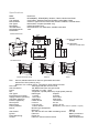
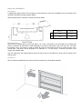
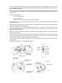
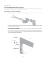
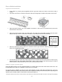
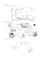
Flameboyant
By Real Fires
Gas Fire Installation Guide
RF-800
Including
RF800 Modern, Classic, Minimal, Pearl.
Electronic and Manual
Natural Gas and Propane
INSTALLATION INTO TIMBER FRAMING, NEW AND EXISTING
MASONRY
Retain these instructions until installation is complete
IMPORTANT NOTES
THIS APPLIANCE MUST BE INSTALLED BY A SUITABLY QUALIFIED PERSON IN ACCORDANCE WITH
LOCAL CODES AND AS 5601 / NZS 5261
THIS IS PRIMARILY A DECORATIVE APPLIANCE AND HAS NOT BEEN DESIGNED AS A SPACE HEATER
THIS APPLIANCE HAS BEEN TESTED TO AS 4558-2000
DO NOT OPERATE
INSTRUCTIONS FIRST
THIS
APPLIANCE
WITHOUT
READING
AND
UNDERSTANDING
THESE
THIS APPLIANCE IS DESIGNED FOR INSTALLATION INTO A TIMBER FRAMED CONSTRUCTION AND
NEW OR EXISTING MASONRY INSTALLATIONS
THIS APPLIANCE MUST INSTALLED USING AN APPROVED TWIN SKINNED B-VENT FLUE SYSTEM
THIS APPLIANCE MUST BE INSTALLED INTO A WELL VENTILATED ROOM IN ACCORDANCE WITH AS
5601/ NZS 5261
THIS APPLIANCE IS DESIGNED FOR INDOOR INSTALLATION ONLY; NOT TO BE INSTALLED
OUTDOORS
REAL FIRES IS NOT RESPONSIBLE FOR INCORRECT OR IMPROPER INSTALLATIONS
ALL INSTALLATIONS MUST BE CERTIFIED
BE SURE TO FILL IN INSTALLER DETAILS SECTION OF THE USER GUIDE BEFORE SIGNING OFF THE
INSTALLATION
-2-
Table of Contents:
IMPORTANT NOTES ............................................................................................................................................. 2
Table of Contents: .................................................................................................................................................. 3
Specifications
...................................................................................................................................................... 4
Notes on Installation: .............................................................................................................................................. 5
Gas Supply ...........................................................................................................................................................5
Electrical Supply ...................................................................................................................................................5
Clearances ...........................................................................................................................................................5
Mantles .................................................................................................................................................................6
Timber surrounds .................................................................................................................................................6
Hearths .................................................................................................................................................................6
Recesses..............................................................................................................................................................6
Flue requirements................................................................................................................................................... 6
Firebox Installation.................................................................................................................................................. 7
Pearl (Glass Trimmed) Fire ..............................................................................................................................7
Timber Framing ....................................................................................................................................................7
Cavity Design ...................................................................................................................................................7
Masonry Cavity.....................................................................................................................................................8
Cavity Design ...................................................................................................................................................8
Preparation of firebox .......................................................................................................................................9
Installing Firebox ..............................................................................................................................................9
Burner Commissioning ......................................................................................................................................... 10
Electronic Burner ................................................................................................................................................10
Manual Burner ....................................................................................................................................................12
Aeration Sleeve Details ......................................................................................................................................13
Pilot Burner Performance ..................................................................................................................................... 13
Trim Installation .................................................................................................................................................... 14
Notes: .................................................................................................................................................................14
Modern and Classic Grated Fronts ....................................................................................................................14
Minimal/Painted Front ........................................................................................................................................15
Pearl/Glass Front................................................................................................................................................16
Burner Media Installation ...................................................................................................................................... 18
Logs/Coals and Vermiculite................................................................................................................................18
Pebbles / Crystals (crushed glass).....................................................................................................................18
Final Checks
.................................................................................................................................................... 19
Wiring
.................................................................................................................................................... 20
Schematic Diagram Electronic ...........................................................................................................................20
Wiring Diagram Electronic..................................................................................................................................20
Wiring Diagram Manual......................................................................................................................................20
Electronic............................................................................................................................................................21
Manual................................................................................................................................................................22
Notes on Installation ............................................................................................................................................. 23
Contact Details .................................................................................................................................................... 24
-3-
Specifications:
Make:
Models:
Trim Options:
Burner Media:
Gas Types:
Description:
Test standards:
AGA Approval No:
Dimensions:
Real Fires
RF800M(N/P), RF800E(N/P), Modern, Classic, Minimal and Pearl
Cast Grates, Stainless Steel and Powder Coated Steel, Glass
Ceramic Logs/Coals and Vermiculite, Ceramic Pebbles, Crushed Glass
Natural Gas, Propane (Australia only)
Indoor Decorative Fire
NZS 5262:2003, AS 4558-2000, AS/NZS 3100:2002
7512
Firebox Dimensions
870
800 **
375 **
410
364 *
230
* APPROX, DEPENDS ON
BENDS
675
627**
658
** FOR MASONRY
INSTALLATIONS ONLY
900
Trim Dimensions
15
720
680
680
13
15
910
910
Modern & Classic Grate
Minimal
990
Pearl
Flue:
200 mm stainless steel inner/ 250 mm galvanized steel outer
200mm Flexi liner (masonry only)
Minimum of 2.4 metres of flue, 3.6 metres if off-set bends are used
Flue Cowl:
AGA Approved 200 mm Flue Cowl
Gas Connection:
3/8" BSPF Gas Flare onto gas control
Power:
230/240V a.c. 50hz, 1 Amp
Fa n:
Tangential; 2 speed (electronic) single speed (manual)
Gas Types:
Natural gas
Propane
Inlet Pressure (nominal)
1.13 kPa
2.75 kPa
Supply Pressure (min/max) 1.0/5.0 kPa
2.0/3.5 kPa
Gas Rate: (high/low)
40/28 MJ/h
40/25 MJ/h
Pressure (high/low)
0.80/0.40 kPa
1.6/0.60 kPa
Pilot Injector:
0.45 mm
0.3 mm
Main Injector:
2 x Ø 2.2 mm
2 X Ø 1.45 mm
Primary aeration:
14.5mm Sleeve
No Sleeve (12mm sleeve for pebbles or crystals)
Burner:
Bunsen type atmospheric
Electronic
Manual
Gas Control:
SIT 845 with SIT 579. DBC modulating control
SIT 630
Ignition:
Electronic
Battery continuous
Flame Monitoring:
Flame rod
Thermocouple
Control:
Electronic Control with IR remote
Manual Adjustment
-4-
Notes on Installation:
Gas Supply
A suitable gas supply needs to be provided to the Left hand rear corner of the installation cavity. The pipe sizing
should be calculated to supply at least 40MJ/h
Allow sufficient pipe to make the connection as shown below:
Electronic
Manual
A
295
250
B
158
172
Electrical Supply
The Firebox is supplied with a power lead approx 1.8 m long. This needs to be connected to an isolating wall
switch, provided by an electrician, located preferably to the right of the Firebox, facing into the room, not inside
the framing cavity. This supply is used to isolate all power for the electronic fires or to control the fan in the
manual fires. The power cord is designed for a 230/240V a.c. 10 amp supply. Electrical connection must
comply with AS/NZS 3000.
note: the manual fire will operate without power but the fan will not, the electronic version will not operate at all
without power.
Clearances
The fire must be installed with the shown minimum clearances to combustible materials
-5-
Mantles
A mantle may be installed above this appliance but must be within the grey
area as shown here.
Timber surrounds
If a timber surround is to be fitted, ensure it complies with minimum timber
clearances of 300mm above (as for mantles) and 150mm each side.
Hearths
Although a Hearth is not required, Real Fires does
recommend that protection is given to any non-combustible
flooring directly in front of the fire. The fire produces a large
amount of radiant heat and this might cause damage to
carpets and furnishings that are too close. Below are the
recommended minimum dimensions for a hearth.
Recesses
If the fire is to be installed into a recess the recess
must comply with the following limitations
Note: The same limitations apply to the sides of the
fire
Flue requirements
Only used an approved cowl
The minimum flue height is 2.4 metres, providing the flue is straight without offsets.
Offsets can be used on flues over 3.6 metres in height.
The flue and cowl must be installed in accordance with AS 5601/NZS5261
Flue
200mm inner flue
250mm outer flue
Cowl
An approved 200mm/250mm cowl must be used.
-6-
Firebox Installation:
Pearl (Glass Trimmed) Fire
For Pearl or other Glass trimmed fires, the
left and right trim hanging tabs need to be
removed to provide a flat surface for the
glass to mount to.
Timber Framing
Cavity Design
NOTE: The firebox and flue need to be installed before the wall can be lined!
It is recommended that the cavity lintel is left off until the flue and firebox have been
installed. (Allow approx 1200mm clearance above the firebox)
Remember that both gas and electricity are required within the cavity
(Refer to Notes on
Installation, page 5)
It is recommended that the fire be installed on a solid platform. If this is not possible then there must be support
provided for at least the first 20mm, and for 45mm at 307mm from the front finished face of the cavity.
•
If the fire is to be installed with a
hearth, either on the floor or
cantilevered, it is important that
the finished top of the hearth is
flush with the floor of the
installation cavity. For the best
finish, allow for the hearth to fit
under the firebox by 5~10 mm.
-7-
Seismic Restraint
If seismic restraint is required then use the strap provided, Slide
the strap through the bottom back rail of the fire box and secure
to the cavity base.
Masonry Cavity
Cavity Design
NOTE: Remember that both gas and electricity are required within the cavity
(Refer to Notes on
Installation, page 5)
Notes:
• These instructions are for either new masonry/non combustible cavities or existing masonry fire places.
• A flexi flue and adaptor is available for installations where access is restricted.
• If the cavity can be completed after the firebox and flue are installed then the adaptor might not be
required.
• The flue adaptor can also be used with rigid flue where space allows.
• The flue should be self supporting before the firebox is installed.
This fire is not designed for installation without a dedicated flue liner
This fire consists of a firebox and removable
insulating panels. For masonry installations
only, these panels can be removed if cavity
space is restricted. Remove as few or as many
panels as required. The more panels retained,
the more efficient the fire will be.
Take care not to damage the power cord when
removing the back panel!
-8-
Preparation of firebox
If the flexi flue adaptor is to be used then there are modifications that need to be made to the firebox.
•
•
•
•
•
Firstly, remove the top insulating panel and
insulation.
Remove the 4 screws holding the twin skin flue
spigot in place and carefully remove the spigot.
DO NOT REMOVE THE WHITE GASKET
Remove the six screws down the side of the spigot
and attach the two spigot rails that are supplied
with the flexi flue spigot
If the top insulation panel is to be used, then it
must be cut to allow the spigot to transition down
the rails. Each panel will end up being about
250mm wide
Remove the two knockouts in the centre of the top
flange of the firebox
Installing Firebox
•
•
•
•
•
Place the firebox onto the hearth and carefully line up the gas supply pipe with the hole in the back left
hand corner of the firebox
Make sure that the power supply cord is passed through the cavity for connection by a registered
electrician (power is not required to operate the manual version of this fire if the fan is not being used
but it is recommended that it is connected regardless)
Line the flue spigot adaptor up with the guide rails on the top of the fire box and push the firebox in.
Take care not to roll the spigot gasket as the firebox slides in!
Once the firebox is fully home, use screws to hold the flue spigot to the top flange of the firebox
Fix the front flange of the firebox to the cavity. If a glass trim is to be used then countersunk screws will
need to be used.
NOTE: It is not necessary to seal the firebox to the cavity.
-9-
Burner Commissioning
Once the firebox has been installed and fixed to the building the gas and electricity can be connected. Some
people elect to leave this until the decorating has been completed and the installation can be finished,
remember that the trim can not be attached until the wall lining is finished.
Electronic Burner
CAUTION Isolate the power and gas supplies before commencing work on the fire!
• Remove the Air Diverter Panel from the front of the Burner Assembly
•
Remove the burner assembly by removing the two fixing screws in front of the burner and pulling the
tray forward and then upwards to remove from the gas control.
•
There may be aeration sleeves attached to the venturi tubes on the back of the burner, take care not to
loose these, there is a chart on page 13 that shows which aeration sleeve should be used depending on
the gas and burner media being used.
•
It may be necessary to remove the gas control assembly in order to make bending and flaring the gas
supply pipe easier. To do this:
o
Remove the fixing screws on the bottom of the assembly and carefully swing the left end of the
assembly out of the cavity. Take care not to pinch or strain the power connection at the
back right corner or the Control Lead in the centre.
o
If it is necessary to remove the assembly completely then use a POZI drive screw driver to
loosen the single screw holding the control panel in place and slide the panel outwards
o
Disconnect the control lead from the back of the control panel and carefully pull the cable back
up into the firebox cavity
o
Disconnect the power, fan and earth connection at the back left corner of the cavity, take note
of the screw and washer holding the earth connection in place (refer page 11)
•
After bending and flaring the gas supply pipe, purge the gas pipe and fix the gas control assembly back
in place and connect the gas.
•
Reconnect the power and gas (reconnect the control panel and fan connection if previously removed)
•
Replace and fix the burner assembly in place
•
Connect a manometer to the inlet test point (refer page 11)
•
Press the ON/OFF button on either the control panel or remote control for at least one second until
the red LED on the control panel glows.
-10-
•
The spark electrode will start to spark across to the pilot and gas will flow through the pilot. If the pilot
does not light within the first minute the ON/OFF button will need to be pressed twice to re-set and restart the ignition sequence.
•
Once the pilot has lit and the gas control has sensed the flame through the flame rod, gas will start to
flow through to the main burner. As soon as the burner has lit fully, press the Flame Up button on the
remote control.
•
Check the Inlet pressure
o
1.0 kPa for Natural Gas
o
2.5 kPa for propane
Adjustment can be made on the inlet pressure regulator
•
Turn the burner off and remove the manometer from the Inlet Test Point and connect it to the Burner
Pressure Test Point
•
Re-start the burner and make sure that the burner is operating at maximum rate by pressing the Flame
Up button until the pressure stops rising.
•
Check the maximum burner pressure against the data plate. If adjustment is necessary then turn the
High Pressure Adjustment Nut on the front of the Gas Control. Take care not to turn the inner Low
Pressure Adjustment Screw
•
Reduce the burner pressure to minimum by holding the Flame Down button on the remote until the
pressure stop dropping.
•
Check the minimum burner pressure against the data plate. If adjustment is necessary then turn the
Low Pressure Adjustment Screw on the front of the Gas Control. Take care not to turn the Outer High
Pressure Adjustment Nut. Recheck the High Pressure setting
•
Turn the burner off and remove the manometer, check all connections and test points for leaks using a
soapy solution.
•
Proceed to the section on Trim Installation (page 14)
-11-
Manual Burner
CAUTION Isolate the power and gas supplies before commencing work on the fire!
• Remove the burner assembly by removing the two fixing screws in front of the burner and pull the tray
forward and then upwards to remove from the gas control.
•
There may be aeration sleeves attached to the venturi tubes on the back of the burner, take care not to
loose these, there is a chart on page 13 that shows which aeration sleeve should be used depending on
the gas and burner media being used.
•
Remove two fixing screws and remove the Gas Control Cover.
•
It may be necessary to remove the gas control assembly in order to make bending and flaring the gas
supply pipe easier. To do this remove the fixing screws on the bottom of the assembly and carefully lift
the assembly out.
•
After bending and flaring the gas supply pipe, purge the gas pipe and fix the gas control assembly back
in place and connect the gas.
•
Reconnect the gas.
•
Replace and fix the burner assembly in place
•
Connect a manometer to the inlet test point (refer page 13)
•
Rotate the Control Knob on the Gas Control to the pilot position push in to make the spark ignitor
operate, gas will begin to flow to the pilot.
•
The pilot should ignite within a few seconds. Note: If the pilot fails to ignite, return the Knob to its original
position and try again. It may take some time to purge all the gas in a new pipeline.
•
Once the pilot is alight, hold the knob in for 5~10 seconds before releasing. The pilot should remain
alight. If the pilot goes out again, repeat the ignition sequence again. If the pilot fails to stay alight after
15 seconds then proceed to the Trouble Shooting section (page 22)
•
Rotate the knob counter-clockwise until it stops at its maximum position, gas will begin to flow to the
main burner.
•
Once the burner has fully lit, check the Inlet pressure
o
1.0 kPa for Natural Gas
o
2.5 kPa for LPG
Adjustment can be made on the inlet pressure regulator
•
Turn the burner off and move the manometer to the Burner Pressure Test Point. Relight the burner and
check the maximum burner pressure against the data plate. Adjustment is made using the Burner High
Pressure Set screw on the side of the gas control.
-12-
•
Turn the knob clockwise to the minimum burner setting and check the minimum burner pressure against
the data plate. Adjustment is made using the Burner Low Pressure Set screw on the front of the gas
control.
•
Push the knob in and rotate clockwise until the burner and pilot are extinguished
•
Remove the manometer and check all connections and test points for leaks using a soapy solution.
•
Proceed to the section on Trim Installation (page 14)
Aeration Sleeve Details
It is important that the correct aeration sleeves are used for each gas type and burner media. The fire should
have been supplied with the correct aeration sleeves. If the fire is to be set up on propane with pebbles or
crystals then the sleeves supplied with the burner media need to be fitted. Refer to the notes supplied with the
burner media and the chart below for more information.
Pilot Burner Performance
When operating at its best, the pilot burner will produce a sharp blue flame with a light blue inner cone. This
inner cone should reach across to the flame rod (or thermocouple) and slightly beyond. The size of the pilot
flame can be adjusted using the screw on the front of the manual gas control but cannot be adjusted on the
electronic version.
Signs of abnormal pilot operation could be:
• A very short flame that does not reach across to the flame rod (or thermocouple). This
could be due to a reduced inlet pressure or a blocked pilot injector
• A very long flame that reaches far beyond the flame rod (or thermocouple). This could
be due an incorrect pilot injector
• A roaring noise when the pilot is operating or the flame “lifting off” from the pilot head.
This could be due to too high an inlet pressure
• Long yellow flames. This could be due to blocked primary aeration of the pilot
Any one of these conditions could affect the performance of the fire (failure to rectify, failure to hold the gas
control open, soot build up on flame rods or thermocouple, etc) and should not be left unresolved.
-13-
Trim Installation
Notes:
•
The outer trim panel cannot be installed until the wall board has been attached and finished (decorated)
•
It is recommended that the installation of the trims and burner media is left until the room is complete
and all decoration is finished.
•
Leave the protective cardboard cover taped to the front of the firebox using a low-tack tape to prevent
plaster dust and debris from entering the firebox and damaging the paint work.
Modern and Classic Grated Fronts
This is the same for both Electronic and Manual versions
•
Remove the front Lower Mounting Screw
•
Fit the Front Trim Assembly so that the lower hook fits over the rear Lower Mounting Screw
•
Fix the Trim Assembly to the Upper Mounting Brackets using an M4 earthing screw (with serrated
washers) at each end.
•
Slide the reflectors into the firebox, between the sides of the firebox and the end of the Trim Grate.
•
Pull the two spring loaded Lower Trim Retainers forward and down until they lock in place as shown
•
Fit the outer trim over the Upper Trim Hooks. If adjustment of the hooks is required, use a screwdriver
to prise the hooks forward, or push them back until the trim fits flush with the wall.
•
Hold the leg of the trim against the Lower Trim Retainer and slide the Retainer upwards into the slot on
the back of the trim, the spring Retainer will pull back into the cavity once the bracket is horizontal
again. WARNING: Take care when the spring grabs that the trim is not resting on the hearth as it
could bite into the surface and scratch it. Either hold the trim slightly higher or use a thin piece
of card between the leg end and the hearth.
Proceed to Burner Media Installation (page 18)
-14-
Minimal/Painted Front
Refer to Notes on Trims (page14) before starting
•
Fit the Minimal Trim so that the two hooks in each end fit over the screws in the side of the firebox as
shown below.
•
Fix the trim in place using an earthing screw (with serrated washer) in one end of the trim.
•
Fit the reflectors by fitting over the front trim at an angle and the standing up against the side of the
firebox. There is a catch above the top edge of the reflector to hold it in place.
•
Pull the two spring loaded Lower Trim Retainers forward and down until they lock in place as shown
•
Fit the outer trim over the Upper Trim Hooks. If adjustment of the hooks is required, use a screwdriver
to prise the hooks forward, or push them back until the trim fits flush with the wall.
•
Hold the leg of the trim against the Lower Trim Retainer and slide the Retainer upwards into the slot on
the back of the trim, the spring Retainer will pull back into the cavity once the bracket is horizontal
again. WARNING: Take care when the spring grabs that the trim is not resting on the hearth as it
could bite into the surface and scratch it. Either hold the trim slightly higher or use a thin piece
of card between the leg end and the hearth.
-15-
Pearl/Glass Front
TAKE CARE WHEN HANDLING THE GLASS PANELS!
DO NOT DROP OR TWIST THE GLASS ASSEMBLIES AS THIS CAN CAUSE THE GLASS PANELS TO
IMPACT ON EACH OTHER AND MAKE THEM CHIP OR SHATTER
Refer to Notes on Trims (page14) before starting
•
Before fixing the trim on, make sure that the trim hanging tabs (used on other models) have either
been removed or flattened to give the trim a flat surface to fix to.
•
Remove the two spring loaded trim retainers and the front panel mounting brackets (used on other
models) refer diagram on page 14.
•
Fit the outer trim to the front of the firebox using 7 screws through the backing panel. DO NOT
OVER TIGHTEN THE SCREWS.
•
Once all of the screws are in place around the trim and front panel, fix the stainless steel caps in
place using a very small dot of silicon. Do not use too much silicon as this can prevent the
caps from sitting flush with the glass.
-16-
•
Remove the upper front bracket screw (this will prevent the front panel from being fitted correctly).
•
Fit the lower Inlet Cover flush with the Outer Trim glass using 2 screws through the base of the fire box.
•
Fit the Upper Inlet Cover as with the Lower Inlet Cover
•
Fit the Front Panel Assembly and hold in place using 2 Earthing Screws (1 in each end of the front).
•
Fit the reflectors by fitting over the front trim at an angle and the standing up against the side of the
firebox. There is a catch above the top edge of the reflector to hold it in place.(refer to minimal
instructions for detail)
•
Fit the Stainless Steel Louvre Overlay over the top louvre by hooking bottom edge onto lower edge of
existing louvre and rotating onto the louvre.
-17-
Burner Media Installation
Logs/Coals and Vermiculite
•
•
Fit the Rear Log Locator panel (supplied with the Logs and Coals) to the back of the burner using 4
screws.
Use a flat screw driver or similar to bend all of the log locating tags up wards until square to the burner.
•
Place (DO NOT POUR*) all of the supplied vermiculite on the burner and spread evenly across the
entire surface of the burner.
•
Place one coal onto each of the 23 Locating Pins. The coals are to be located centrally and at the same
angle as the tag. Push the coals down until they are just sitting on the bed of vermiculite.
*Pouring
the
media over the
burner can block
the burner ports
with the fine dust
that tends to settle
in the bottom of
the bags during
shipping
•
Place the remaining coals (a total of 27 should be used to get maximum efficiency) and the supplied
twigs over the first row of coals.
•
Once all the logs and coals are in place, light the fire and assess the look of the flames. If there are any
areas that have very long streaky flames then, using a pair of tongs, move the top logs or coals to
another position until the flames are more even across the whole burner.
Pebbles / Crystals (crushed glass)
Place (DO NOT POUR*) all of the supplied Pebbles or Crystals evenly across the entire area of the burner. The
finished depth will be about 2~3 pebbles or about 20 mm of Crystals.
Do not pile glass or pebbles over the top of the pilot assembly as this could affect it performance. It may be
possible to build the media up around the pilot to hide it slightly but always check that the pilot is operating at its
optimum when finished. (Refer to Pilot Burner Performance page 13)
*Pouring the media over the burner can block the burner ports with the fine dust that tends to settle in the bottom of the bags during shipping
-18-
Final Checks
Check that the fire operates properly in all modes (high & low gas rates, fan high & low; low only on manual
model.)
Make sure that all the supplied parts are used and properly installed.
It is important that the customer is fully aware of how to operate the fire properly and safely.
Advise the customer of the need for regular servicing in order to maintain the warranty.
Advise the customer to fully read the User Guide to understand how to get the best out of their fire and keep it
looking its best.
Fill in the “Installer Details” section in the back of the user guide.
-19-
Wiring
Schematic Diagram Electronic
Wiring Diagram Electronic
Wiring Diagram Manual
-20-
Trouble Shooting:
Electronic
Problem
Possible Cause
Remedy
ON/OFF Button
(front panel) does
not work (no spark
noise)
Mains Power Disconnected
Check mains supply and isolating switch
Gas Control locked out
Press ON/OFF button twice to reset *
Faulty control
Service call
Button not held for 1 second
Hold button for on second
Flat batteries
Replace batteries
Signal interference
Move to another part of room
Faulty remote
Replace remote control
Faulty receiver
Service call
Gas control locked out
Press ON/OFF button twice to reset *
Button not held for 1 second
Hold button for on second
Air in gas pipe
Purge gas pipes *
Gas supply turned off/empty
Turn on gas supply or change bottles *
Faulty flame rod
Service call
Dirty gas in bottles (LPG/Pro)
Replace or change over gas bottles
ON/OFF Button
(remote) does not
work (no spark
noise) but front
panel does
Fire is sparking then
locks out
Pilot flame starts but
spark keeps going
Pilot ignites but main Faulty gas control
flame does not
Service call
Fire goes out
Gas Supply turned off or empty
Check gas supply or change/replace bottles
Power supply turned off
Check power is on
Accidental operation of remote
control
Check location of remote control
Flat batteries in remote control
Replace batteries
Faulty receiver
Service call
Faulty fan or wiring
Service call
Fan does not
operate
* If the fire fails to ignite after 3 attempts, turn off the power and gas if possible and arrange a service
call or contact the installer if fire is new.
-21-
Manual
Spark electrode
does not fire
Electrode sparks
but pilot does not
light
Pilot lights but
does not stay
alight
Pilot stays alight
but main burner
does not light
Fan does not
operate
Disconnected HT lead
Connect HT lead
Faulty HT Lead
Service call
Air in gas pipe
Purge gas pipes
Gas supply turned off/empty
Turn on gas supply or change bottles
Valve not held long enough
before sparking
Hold valve open longer before activating the sparker
Pilot flame not sufficient to hold
thermocouple operated valve
Refer to pilot operation, page 13
Faulty valve
Service call
Not holding flame long enough to
hold valve
Hold pilot flame longer to allow thermocouple to
generate enough voltage to hold valve open
Burner media is blocking cross
lighting holes on main burner
Move any logs, coals, etc. that might stop burner
cross lighting
Control valve not fully open
Rotate control valve fully anti-clockwise
Faulty gas control
Service call
Power not on/connected
Check that the power is connected and on
Faulty fan or wiring
Service call
-22-
Notes on Installation
Please write any installation specific notes on this page and leave with the customer for future reference:
-23-
Contact Details
Flameboyant.com.au
Regency Fireplace Products Australia Pty Ltd.
21-23 South Link
Dandenong
South Vic 3175
Australia
Phone 1 800 081 978
Fax 03 9799 7822
Email [email protected]
-24-
RF800 INSTALLATION GUIDE
ISSUE: B
66000-B
By Real Fires
Electronic Range RF800
User Guide & Service Manual
Models
Minimal
Pearl
Modern
Classic
Thank you for choosing to purchase a Real Fires fireplace for your home.
Our products are proudly New Zealand inspired and manufactured from
the finest materials.
This User Guide is designed to familiarise you with the fire,
its features, operation and care. We know you will get many years
of enjoyment from your Real Fires fireplace.
Congratulations on your purchase.
Warmest regards
Ali Fenton
Company Director
Real Fires Electronic Range RF800
User Guide & Service Manual
Models Pearl, Minimal, Modern, Classic
Contents
Important Notes
2
Specifications
2
Fire Features
3
Operating Instructions
3
Remote Control Notes
4
Remote Control Operation
4
Auto Off Timer
4
Logs and Coals, Pebbles, Glass
5
Safety
5
Power Failure
5
Cleaning
6
When to Call for Service
6
Warranty Statement
7
Conditions of Warranty
7
Service
7
Servicing Requirements
7
Service Instructions
8
Wiring Diagram
10
Parts Diagrams
11
Troubleshooting
12
Installation Information
13
Service Record
14
Real Fires Warranty Registration
15
1
Real Fires Electronic Range User Guide & Service Manual
Important Notes
This appliance has been tested in accordance with AS 4558-2000 and
NZS 5262:2003 and has been certified by the Australian Gas Association
(Certificate Number 7512).
DO NOT OPERATE THIS FIRE WITHOUT READING AND UNDERSTANDING
THESE INSTRUCTIONS. Please keep these instructions for future reference.
FOR YOUR SAFETY
DO NOT PLACE ARTICLES ON OR AGAINST THIS APPLIANCE.
DO NOT USE OR STORE FLAMMABLE MATERIAL NEAR THIS APPLIANCE.
DO NOT SPRAY AEROSOLS IN THE VICINITY OF THIS APPLIANCE.
PRIMARILY A DECORATIVE APPLIANCE – NOT CERTIFIED AS A
SPACE HEATER.
WHAT TO DO IF YOU SMELL GAS
• Do not try to light any appliances.
• Do not touch any electrical switches; do not use any phone in your building.
• Shut off valve at the gas meter or cylinders.
• Call a technician.
Real Fires gas fires are designed to provide warmth, comfort and
ambience for your home. The Electronic range of Real Fires incorporates
electronic flame control and an integrated two-speed fan, all operated
from a remote control.
Please take some time to read these instructions and familiarise yourself
with its features and operations so that you will get the most out of your
Real Fire for years to come.
Specifications
2
Make
Real Fires
Model
RF 800 (Minimal, Pearl, Modern and Classic)
Available Gas Type
Natural Gas, propane
Power Consumption
230 V a.c. 70 Watts max
Gas Consumption
40 MJ/h max
Fan
Two-speed
Gas Control
Electronic
Fire Features
Hot Air
Outlet Louvre
Outer Trim
Reflectors
Burner Media
(Logs, Coals/
Pebbles/ Glass)
Front Panel
Control Panel
Air Intake
Operating Instructions
To operate your fire for the first time,
ensure that the gas supply is on and that
the fire has been tested and certified by
the installer.
Switch on the power supply to the
Real Fire. This is usually a wall switch near
to the fireplace.
Operation LED
ON/OFF Button
Control Panel
Remote Receiver Window
The Real Fire can now be started by
using either the Control Panel or the Remote Control.
Start the fire by pressing the ON/OFF button for at least one second until the
red light on the Control Panel comes on.
Note: If the fire has not been used for some time then it may take some time
to start as the gas in the pipes may need to purge. The fire will try to start for
up to one minute before ‘locking out’. If this happens, then press the ON/OFF
button twice to reset then restart the fire. If the fire has not started after three
attempts, contact the installer or a Real Fires representative.
It is recommended that the fire is started on its maximum gas rate (refer to the
Remote Control section on page 4).
Once the pilot has ignited, then gas will begin to flow to the main burner. The
flames should be right across the burner within about 10 seconds. If the burner
does not light or only lights part-way across, then turn the fire off immediately
and call a service technician for further advice.
The fire can be stopped by pressing the ON/OFF button on either the Remote
Control or the Control Panel. The flames may take a few seconds to fully
extinguish. This is normal and is not a cause for concern.
3
Real Fires Electronic Range User Guide & Service Manual
Remote Control Notes
There are a few things you should know about your Remote Control to keep it
working at its best:
•
It uses four AAA batteries. With new batteries the Remote Control will
work from about 8 metres away from the fire.
•
When replacing the batteries, replace all four; do not mix old with new.
•
Remove the batteries if the fire is not going to be used for extended periods.
•
Some fluorescent lights can affect the performance of the Remote Control.
•
Avoid dropping the remote or getting it wet.
Remote Control Operation
Point the Remote Control towards the fire and press
the Power Button for about one second. The fire will
then commence the ignition sequence. As the fire is
lighting, press the Flame Control button to the + high
flame. This ensures the fire ignites on high flame.
Always run the fire on high for at least a few minutes
to ensure a quick warm-up of the firebox and flue.
The fire can then be turned down if desired.
The flame can be controlled simply by pressing the
remote Flame Control button + or – to increase or
decrease the flame.
Power
Flame
Control
Fan
Control
Auto Off/
Cancel
The electronic Real Fire has a two-speed fan. The fan
is also controlled from the Remote Control by pressing the Fan Control button
+ or – to switch the fan on/off or high/low.
To switch the fire off, press the Power button on the Remote Control.
Auto Off Timer
By pressing the Auto Off Timer button on the Remote Control the fire can be
set whilst in operation for a 30-minute delayed switch-off. The red indicator
light on the Front Panel of the fire will flash when this mode has been activated.
Pressing the Auto Off Timer button a second time will cancel this mode.
4
Logs and Coals, Pebbles, Glass
The Logs and Coals, Pebbles, or Glass should have been positioned correctly
by the installer. It is not intended that these are repositioned by the user.
Incorrect positioning can affect heat output and ignition. Only Logs and Coals,
Pebbles and Glass supplied by the manufacturer may be used in this fire.
Due to the nature of luminous flames used in this fire a slight build-up of carbon
may be seen. This is quite normal and will not affect the performance of the fire.
Safety
Real Fires are factory tested and the installation should have been tested by the
installer. You should not experience any odour from your fire other than an initial
burn-off smell the first time it is used. Should any additional odour be noticed,
turn off the gas supply and arrange for a gas fitter to make a service call.
Your Real Fire has a flame failure safety system which ensures that in
the event of an ignition failure, gas supply failure or pilot flame being
extinguished for any reason, the fire will shut down. The fire will attempt to
restart automatically. If the fire fails to reignite, then the fire will ‘lock out’ and
will need to be reset manually by pressing the ON/OFF button twice to reset
and restart the ignition sequence.
Wait at least 10 seconds before attempting to restart the fire and if the fire
fails to ignite after three attempts, then turn off the power and refer to the
Troubleshooting section on page 12 or consult a technician.
Real fires burn with a real flame and as such there are considerations
to be made to ensure the safety of children and the infirm. In such
circumstances a fireguard should be secured in front of the fire.
Do not place furniture and other objects within one metre of the fireplace.
Make sure that the lower and upper air inlets are not blocked as this
could cause damage to the fan or cause the gas controls to overheat.
Power Failure
In the event of a power failure, your Real Fire cannot be operated.
5
Real Fires Electronic Range User Guide & Service Manual
Cleaning
Regular cleaning of your Real Fire is important to keep it looking its best.
Some points on cleaning:
•
Do not use abrasive cleaners on any panels.
•
All of the exterior painted panels can be cleaned using household cleaners.
•
The black interior panels and the Logs and Coals may develop a slight build-up
of soot; this is quite normal and may burn off over time. Do not try to remove
the soot by rubbing with a cloth as this will only spread the soot around.
•
Do not vacuum the burner media, especially the Log and Coal bed
(vermiculite) as it is very light and the burner is not designed to be
operated without this media on top.
•
The stainless steel reflectors and Front Panel (if fitted) can be cleaned
using a household stainless steel cleaner.
•
The glass panels (Pearl model) can be cleaned using a household glass
cleaner but do not spray the glass cleaner directly onto the glass. This can
result in the cleaner tracking between the glass and the trim behind and
can cause water-spotting that can remain for some time.
When to Call for Service
The following signs indicate that your fire requires a service call:
•
If long, streaky flames are touching the back of the firebox, this can cause
the paint to blister and possibly damage the fire.
•
If you can smell gas, whether the fire is going or not (there could be a
small smell of gas as the fire is going through the ignition sequence but
this should stop once the fire has started).
•
If the pilot flame looks abnormal. Signs of abnormal pilot operation could be:
-- A very short flame that does not reach across to the flame rod.
-- A very long flame that reaches far beyond the flame rod.
-- A roaring noise when the pilot is operating or the flame ‘lifting off’
from the pilot head.
-- Long, yellow flames.
6
•
If there are large soot deposits that keep building up on the burner media.
•
If there is excessive noise or explosive ignition as the burner lights; this
could be due to blocked burner ports.
•
If a smell of flue gas continues after the fire has been operating for at least
10 minutes. This could indicate a blocked flue or other problem. This smell is
acceptable during the first few minutes as the flue heats up and starts to draw.
•
If the flames change shape or colour. When the fire first starts, the flames
will tend to be quite blue for a few minutes but will change to a more
yellow/orange colour as the system heats up. This is normal, but if the
flames either stay very blue, or turn a dark, streaky, orange colour, this
could indicate a problem.
Warranty Statement
Fifteen-year warranty on Real Fires firebox
Three-year warranty on Real Fires gas burner
Two-year warranty on control parts
Two-year labour warranty
Warranty does not include paint inside firebox
Conditions of Warranty
The labour warranty includes vehicle travel cost up to 30 km from place of
purchase or a Real Fires-approved service gas fitter.
The maximum period between servicing is two years before the warranty is void.
The warranty does not cover damage caused through building defects,
incorrect installation or incorrect use.
The warranty period is taken from the date of commissioning by the installer.
Ensure that the installer has filled in the Installer Information section of this
User Guide on page 13.
Service
In order for your Real Fire to give years of comfort and enjoyment, Real Fires
recommend that your Real Fire is serviced on an annual basis by a licensed
service gas fitter. Please refer to the back of this User Guide for contact details.
Servicing Requirements
A regular service must include:
• Inspect/clean the main burner, aeration sleeves, and media
• Inspect/clean the pilot and injector
• Inspect/clean the main injectors
• Check burner pressures
• Clean the fan
• Check operation of fire, including fan
• General inspection of firebox and flue
7
Real Fires Electronic Range User Guide & Service Manual
Service Instructions
Disconnect the mains power before commencing any service work.
Servicing is only to be carried out by a certified gas fitter.
Refer to the Parts Diagrams on page 11 for more details.
It is not necessary to remove the outer trim but it is recommended to do so
with the non-glass trims as they can be scratched during service if not careful.
Remove the outer trim (metal trim only) by carefully pulling the bottom of the
trim leg outwards until the spring-loaded trim retainer is at its limit. Push the
retainer down and the leg should become free. Once both sides are free, lift
the trim up off the top trim hangers.
Remove the side reflectors: (Note: there is a tab at the top centre of each
reflector holding it in place, this will need to be lifted up to release the reflector.)
•
Minimal and Pearl fires – This is done by pulling the top of the reflector
out slightly and rotating the top of the trim towards the centre of the
firebox and lifting it away from the burner.
•
Modern and Classic fires (grated front) – This is done by pulling the
reflectors straight out of the fire. Take care not to scratch the outer trim if
it is still attached.
Remove the front panel:
•
Remove the earthing screws on the top left and right of the front trim
and carefully lift the trim straight up until free of the locating screws. If
the outer trim has not been removed it may be necessary to lift the front
panel up until it can be rotated into the firebox for removal.
Remove the main burner:
•
Remove the two screws holding the burner assembly in place. Slide the
burner and tray out and lift upwards.
•
If servicing the pilot only, the burner media can be left as it is on the
burner, otherwise:
-- Carefully remove the burner media and inspect the burner for signs
of wear or damage.
-- Vacuum the top burner ports and inspect the Primary Aeration
ports and Aeration Sleeves (if fitted) on the underside of the burner;
vacuum if required.
8
Check the main injectors
•
Inspect the injectors for any sign of damage or blockage and remedy
as required.
Service the pilot:
•
Inspect the pilot and flame rods for any signs of damage or wear. By
blocking the main injectors (a silicon tube across both injectors works well)
the fire can be started and operated with just the pilot operating if required.
•
Remove the front pilot assembly bracket and the pilot head can be removed
and cleaned; the pilot injector can now also be inspected and cleaned.
•
If replacing the pilot injector, remove the retaining nut on the base of the
pilot body and remove the pilot injector using a small, flat screwdriver.
•
Inspect the flame rods and leads for signs of damage and replace if
required. Note: There might be a slight build-up of soot on the flame rods
and this should be removed to help ensure continued operation.
Service the fan:
•
•
Remove the fan cover by removing the 4 screws holding it in place.
With the cover removed it should be possible to inspect and vacuum the fan
to remove any build up of dust and lint. Note: if replacement of the fan is
required, the gas will need to be disconnected and the gas control assembly
removed to gain full access to the fan bracket. Replace the cover when done.
Inspect the firebox:
•
Check the gas control assembly – valve, control box, regulator, wiring,
panels etc. – for any signs of overheating, water damage or anything else
out of the ordinary and remedy as required.
Reassembly:
•
Re-assemble the pilot
•
Check that the Aeration Sleeves (if fitted) are in place and in good
condition
•
Return the main burner assembly to its correct position and fasten in place.
•
Return the burner media as it was. Do not pour the vermiculite, Pebbles,
or Glass onto the burner as any dust that has gathered can block the ports
and cause problems.
9
Real Fires Electronic Range User Guide & Service Manual
Recheck burner pressure:
•
Connect a manometer to the burner pressure test point.
•
Reconnect the power and start the fire.
•
Using the remote control, adjust the burner pressure to its maximum and
check the pressure against the data plate.
•
Adjustment of the burner pressure is done using the nut and screw shown
on the diagram on page 11. Take care not to turn the low pressure set
screw when adjusting the high pressure and vice versa.
•
Adjust the burner pressure to its lowest setting and check against the data
plate. Recheck the high pressure set again.
•
Check the look of the flames when the fire has warmed up a little and
move any Logs/Coals that appear to be causing long, streaky flames.
•
Turn the fire off, and remove the manometer.
•
Check the test point for leaks.
•
Replace the Front Panel, reflectors and side trim. Take care not to scratch
the hearth when refitting the outer trim.
•
Re-test all functions of the Remote Control (burner high and low, fan high
and low, on and off).
Wiring Diagram
CONTROL BOX
(Millennium)
CAT 5 CABLE
TO RECEIVER
1
BLU
FUSE
GAS CONTROL 12-PIN PLUG
3 AMP
SPARK
13/14
FLAME
GR
PILOT
4
3
2
1
OR
SPARK
1 GAS CONTROL 12
(SIT845 with 0.579.506 DBC)
10
WH (HT LEAD)
BLU
WH
RD
GR
GR
BLU
BRN
2
BRN
NEUTRAL
NEUTRAL
BLU
LOW
MED
RD
YL
BRN
WH
1 - EMPTY
2 - EMPTY
3 - EMPTY
4 - EMPTY
5 - BLK
6 - BLK
7 - BLK
8 - EMPTY
9 - EMPTY
10 - BRN
11 - BLU
12 - GR
YL
ACTIVE
HIGH
MAINS IN
230/240 V a.c.
50 Hz
10 AMP
MOD 2
MOD 1
COLOUR
WHITE
BLACK
YELLOW
RED
BLUE
BROWN
GREEN / YELLOW
ORANGE
13
14
WH
BLK
YL
RD
BLU
BRN
GR
OR
Parts Diagrams
Fan Cover
Main Injectors
(with Tube attached)
Fan
Control Box Cover
Pilot
Assembly
Power Supply
Regulator
Trim
Mounting
Brackets
Trim
Retainer
Control Lead
& Grommet
Control Box
Fuse
Gas Control Assembly
Gas Contro Valvel
Earth Tab
Aeration
Sleeves
Control Panel
Spring
Washer
Pilot Head
Pilot Bracket
Nut
Flame Rods
Burner Pressure
Test Point
Inlet Pressure
Test Point
Pilot Front
Bracket
Pilot Body
Pilot Spring
Pilot Injector
Retainer
Low Pressure
Set Screw
High Pressure
Set Nut
Pilot Injector
Fixing Screws
Burner Assembly
11
Real Fires Electronic Range User Guide & Service Manual
Troubleshooting
Problem
Possible Cause
Remedy
ON/OFF Button
(Front Panel) does
not work (no spark
noise)
Mains power
Disconnected
Gas control locked out
Button not held for one
second
Air in gas pipe
Check mains supply and
isolating switch
Press ON/OFF button
twice to reset *
Service call
Hold button for one
second
Replace batteries
Move to another part of
room
Replace Remote Control
Service call
Press ON/OFF button
twice to reset *
Hold button for one
second
Purge gas pipes *
Faulty flame rod
Service call
Faulty gas control
Blocked burner ports
Gas supply turned off or
empty
Power supply turned off
Accidental operation of
Remote Control
Flat batteries in Remote
Control
Faulty receiver
Faulty fan or wiring
Service call
Service call
Check gas supply or
change/replace cylinder
Check power is on
Check location of
Remote Control
Replace batteries
ON/OFF Button
(Remote Control)
does not work (no
spark noise) but
Front Panel does
Fire is sparking then
locks out
Pilot flame starts but
spark keeps going
Pilot ignites but main
flame does not
Fire goes out
Fan does not
operate
Faulty control
Button not held for one
second
Flat batteries
Signal interference
Faulty remote
Faulty receiver
Gas control ‘locked out’
Service call
Service call
*If the fire fails to ignite after three attempts, turn off the power and gas if
possible and arrange a service call or contact the installer if the fire is new.
12
Installation Information
Installer’s Name
Registration Number
Certification Number
Date of Installation
Date of Commissioning
Real Fire Model
Burner Media Installed
Serial No. (from data plate)
Date of Manufacture (from data plate)
Owner’s Name
Installation Address
13
Real Fires Electronic Range User Guide & Service Manual
Service Record
Serviced by
Registration No.
Company
Date
Registration No.
Company
Date
Registration No.
Company
Date
Registration No.
Company
Date
Registration No.
Company
Date
Comments:
Serviced by
Comments:
Serviced by
Comments:
Serviced by
Comments:
Serviced by
Comments:
14
Real Fires Warranty Registration
Please fill in the details below as requested and return to Real Fires NZ Ltd in
order to ensure your Real Fire Warranty is registered.
Owner’s Name
Owner’s Address
Installation Address (if different from above)
SEE INSTALLATION CERTIFICATE FOR DETAILS REQUESTED BELOW
Real Fire Model
Serial No.
Date of Manufacture
Date of Installation
Date of Commissioning
Installed by
15
Real Fires Electronic Range User Guide & Service Manual
Fold here, tape and return
Affix
stamp
here
Real Fires NZ Limited
PO Box 100744
North Shore,
North Shore City 0745
New Zealand
Service Record
Serviced by
Registration No.
Company
Date
Registration No.
Company
Date
Registration No.
Company
Date
Registration No.
Company
Date
Registration No.
Company
Date
Comments:
Serviced by
Comments:
Serviced by
Comments:
Serviced by
Comments:
Serviced by
Comments:
17
contact
Flameboyant.com.au
Regency Fireplace Products Australia Pty Ltd.
21-23 South Link
Dandenong
South Vic 3175
Australia
Phone 1 800 081 978
Fax 03 9799 7822
Email [email protected]
65000 | Issue B
| User Guide RF800 Electronic