1
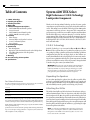
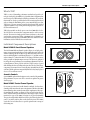
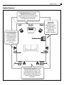
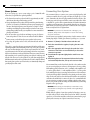
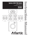
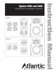
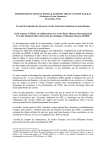
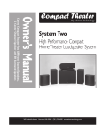
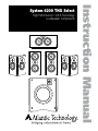
High Performance C.O.R.E. Technology Loudspeaker Components Instruction Manual System 4200 THX Select Table of Contents System 4200 High Performance Loudspeakers Table of Contents 2 2 2 3 3 C.O.R.E. Technology Unpacking the Speakers Attaching the Grilles What’s THX? Individual Component Descriptions 3 4 4 4 Model 4200 LR Front Channel Speakers Acoustic Controls Model 4200 C Center Channel Speaker Models 4200 SR Surround Speakers 4 4 4 6 Home Theater Surround Effects and Speaker Locations 6.1 and 7.1 Channel Systems Stereo Systems 4 Placement 6 Connecting Your System 8 System Setup 8 8 8 9 Bass Management Operation of the Rear Panel Controls on the LCR Speakers Dipole/Bipole Operation of the SR Speakers Setting Levels 9 Mounting 10 Care and Feeding of Your Speakers 10 Specifications System 4200 THX Select High Performance C.O.R.E. Technology Loudspeaker Components Thank you for choosing Atlantic Technology products. Your new speaker components are precision-crafted to give you years of enjoyable, trouble-free service. This manual covers the Atlantic Technology System 4200 speaker components. It will show you how to incorporate these components into your present setup, as well as how to assemble a complete system from them. The Model 642 SB box-type enclosure subwoofer is covered in detail in a separate manual. This system can be used with all current and past sound formats including Stereo, Dolby Surround®, Pro Logic®, Dolby Digital 5.1®, Dolby Digital EX®, DTS®, DTS ES®, DTS ES Discrete®, DTS Neo:6®, DVDAudio and SACD Audio. C.O.R.E. Technology C.O.R.E. (Technology) is an acronym for Custom Optimized Room Enhanced. These systems allow you to optimize the custom aspects of the core package by adding optional Accent Panels and building up different configurations using box subs, and dipole, bipole, or direct radiator surrounds. Room Enhanced refers to the high degree of room acoustic matching and source optimization offered by the system components. Your 4200 speakers are available in a variety of colors. If you want to change the finish to another color, please contact your Atlantic dealer. IMPORTANT: Although it may seem like asking for driving directions, please take a few moments to read all of this booklet. It has many helpful tips and ideas on properly setting up and using your system. We promise that if you take the time to read and follow these tips you’ll get better system performance and more enjoyment. Unpacking the Speakers For Future Reference Record the serial number and date of purchase for each speaker here. The serial number is found on the speaker terminal panel on the back of the enclosure. Serial Number Serial Number Serial Number Date of Purchase The contents of this manual are Copyright © 2003 by Atlantic Technology International, Corp., and may not be duplicated or reproduced by any means, whether physical, electronic or otherwise without prior written consent from Atlantic Technology International, Corp. Atlantic Technology and the Atlantic Technology logo are registered trademarks of Atlantic Technology International, Corp. Specifications are those in effect at the time of printing.Atlantic Technology International, Corp. reserves the right to change specifications or designs at any time without notice without obligation to modify existing units. Use care when unpacking the speakers. Since the grilles are packed off the speakers, be particularly careful of the driver elements as you unpack and move the speakers. Remember to keep the original boxes and packing material, in the unlikely event the speakers need servicing, or if you move. Attaching the Grilles The included metal grilles are held to the front of the enclosures with powerful neodymium magnets. There are depressions on the back of the grille that the magnets fit into. Once the speakers are in their final position and the optional Accent Panel Kits have been installed remove the grille from its protective plastic bag and carefully position it over the magnets on the baffle. Move them together slowly and when you get close enough, the magnets will draw the grille in and hold it tight. Be careful not to get your fingers caught between the grille and the cabinet. NOTE: You will notice a threaded insert in the bottom of the LR satellites. This is for bolting the satellites to speaker stands that utilize a through hole in the middle of the stand’s top plate. Use a 1/4” x 20 bolt to secure the LR to the stand. Individual Component Descriptions Instruction Manual What’s THX? Figure 1 THX is a series of demanding performance standards and specific technologies developed by Lucasfilm Ltd. (of Star Wars fame). Equipment that meets the rigorous THX standards will deliver performance in your home that matches as closely as possible what the director/artist/engineer heard and saw during the final mixing of the source material. Please note that THX is not a separate surround sound decoding format. THX-certified equipment enhances every viewing and listening experience, regardless of the surround format used. THX Select standards are based upon a room size of 2000 cubic feet (L x W x H). This does not mean these components must be used in a rooms this size. The room sizes simply provide a frame of reference, as they indicate that these systems must deliver a minimum level of performance in this specified room size.Your System 4200 is THX Select certified. For more information, visit the THX website at www.thx.com. 4200 LR Individual Component Descriptions Figure 2 Model 4200 LR Front Channel Speakers The Model 4200 LR Front Channel Speakers (Figure 1) are high-performance 2-way systems intended for use with a quality subwoofer, such as the Atlantic Technology Model 642 SB box-type subwoofer. Each speaker contains two GLH (Graphite Loaded Homopolymer) 5 ¼” (135mm) woofers and an advanced 1” (25mm) ferrofluid-cooled, damped silk dome tweeter with a powerful neodymium magnet structure. The drivers are configured in a D’Appolito array (midrange-tweeter-midrange alignment) This vertical arrangement of drivers provides wide left to right coverage of sound while limiting the floor and ceiling reflections that color the sound. These components are mounted in an acoustically inert internally braced MDF enclosure. The LR speakers are magnetically shielded so they may be placed close to a TV set without concern. 4200 C Figure 3 Acoustic Controls System 4200 LR speakers include unique acoustic controls to help maximize their performance in your room. These controls are explained in greater detail on page 8. Model 4200 C Center Channel Speaker For accurate reproduction of a multi-channel soundtrack, the three frontchannel speakers must have the same sonic signature. Therefore, the 4200 C Center Channel speaker contains the same driver complement as the respective matching LR speakers (see Figure 2). They are both designed for use with a dedicated subwoofer and include the same unique acoustic controls mentioned on page 8. The 4200 C is designed to be placed horizontally. They are also magnetically shielded and can be placed directly adjacent to your TV set with no adverse effects on the television’s picture. The 4200 C can be tilted on its dedicated base to provide optimum sonic coverage of the listening area. 4200 SR Placement System 4200 High Performance Loudspeakers Model 4200 SR Surround Speakers Surround Effects and Speaker Locations The Model 4200 SR Dipole/Bipole Surround Speakers (Figure 3) are intended for use in multi-channel audio/video sound systems as dedicated side or back surround channel speakers. The 4200 SR enclosure has two 4 ½” (115mm) GLH woofers and two of the same high performance silk dome tweeters found in the 4200 front speakers. The surround speakers can be switched between Dipole and Bipole operation. These settings are explained on page 8,“Dipole/Bipole Operation of the SR Speakers.” The 4200 SR’s shape allows great flexibility in placement. Due to the switchable Dipole/Bipole design, it’s possible to place the speakers almost anywhere within the rear third of the room and get good results. However, the best location for surround speakers is straight out to the sides, or slightly behind the primary listening area, approximately 1-2 feet (.3,.6m) above seated ear level, but no closer than 2 feet (.6m) from the ceiling. As noted above, the surround speakers (as opposed to the back speaker(s) in a 5.1, 6.1 or 7.1 channel system, see below) are primarily intended to re-create the ambient sounds taking place in the movie scene. Therefore, throughout most of a movie or TV program you may not be consciously aware of output from these speakers. In other words, don’t worry if you aren’t hearing the surround speakers. Please try to avoid the trap of turning the surrounds up and up so that you hear them most of the time. The result will be a much less believable surround experience. NOTE: Although the speakers in the Atlantic Technology System 4200 are acoustically and cosmetically matched to each other for ideal results, they may also be used with other Atlantic Technology components and a wide variety of speakers from other manufacturers with excellent results. Placement Speaker/room interactions have a huge impact on the sound of the system. Moving the speakers just a little can make a dramatic difference in what you hear. Remember that the best acoustic placement of the speakers will vary from room to room. Use the following placement guidelines (see opposite page) as a starting point. But also feel free to experiment. In fact, it may be beneficial to hook up the front LR and surround speakers with some extra wire and to simply drape the wire across the floor before installing the speakers permanently. This will allow you the opportunity to move the speakers around easily so you can find the best sonic and visual locations. Home Theater Remember that the primary goal of a good home theater is not to make you believe that you are in a movie theater. It’s to make you believe you’re in the movie. For a home theater system, place the LR speakers on either side of the television. The three front channel speakers (LR and C) are magnetically shielded so they will not interfere with your television picture. The left and right front speakers should be far enough apart (6 to 10 feet, 2-3 meters, is usually best) that you get a good stereo “image” when they are playing alone, but not so far apart that the sound seems to be disembodied from the TV, distracting you from the picture. When using a center channel speaker, a wider separation of the left and right front speakers is usually possible. You may chose to “toe” the LR speakers in, aiming them approximately at the prime listening position. This can be particularly useful if the front LR speakers are fairly far apart. IMPORTANT NOTE Try to keep the LR and C tweeters at approximately the same height and aimed at ear level when seated. This is because we’ve designed the alignment of the drivers on the front panel to limit the vertical spread of the mid and high frequencies, thereby reducing the floor and ceiling reflections that adversely affect sound quality. If the speakers are too high or too low however, you will miss a significant portion of the upper middle and high range elements of the sound. This alignment of the drivers provides enhanced horizontal spread of the sound making for a much better sound experience for a group o f listeners and reducing the need to sit in a precise “sweet spot.” There are dedicated LEFT and RIGHT model 4200 SR speakers. This is clearly marked on the back of each speaker. Be sure that the Left side surround speaker is placed directly to the left side of the prime listening area (facing the screen) and the Right speaker is directly to the right side. As an easy reference, the Dipole/Bipole switch should always be facing the back of the room. 6.1 and 7.1 Channel Systems For best performance in a 7.1 channel system, we recommend using another pair of 4200 LR's on the back wall, and 4200 SR's on the side walls. If you are setting up a system that uses back surround speaker(s) as well as side surrounds (Dolby Digital EX, DTS ES, etc.) you can choose to use either SR model speakers in Dipole or Bipole mode or another pair of front LR speakers in the back of the room. If the 4200 SR’s are used as back surrounds in a 6.1 or 7.1 channel system, they should be installed with the Right speaker placed over the listener's left shoulder and the Left speaker placed over the listener's right shoulder; these back surrounds should be placed approximately 150 degrees from the screen on the back wall. About one-third of the way out from the corners in most rooms is a good starting point. If you are using a THX Ultra 2 certified controller/receiver, you should place the back surround speakers approximately 1 to 2 feet (.3,.6m) apart in the center of the back wall. The special circuitry in the processor will help to create a believable and effective surround field using this placement. Please read the electronics manual to learn more about this placement option. Speaker Placement Instruction Manual Speaker Placement Front Speaker Array should be placed as close to ear level as possible. Generally, the farther away the speakers are from the walls, the better they will sound. Left Surround Speakers should be placed directly to the sides of the seating area and approximately 3 feet (1 meter) above the listener’s ear level. Left Surround Left Surround Back Center Right Subwoofer placement is dependent on room size and shape. Experiment to find a location that produces the smoothest response. Subwoofer Right Surround Right Surround Back Surround Back Speakers should be placed approximately 3 feet (1 meter) above the listener’s ear level and 30° off the center axis. Direct radiators (4200 LRs) may be used here, with or without an subwoofer. Connecting Your System System 4200 High Performance Loudspeakers Stereo Systems Connecting Your System If you are setting up a stereo system using a pair of 4200 LR’s with subwoofer(s), begin with these general guidelines: We recommend that you connect your system using high quality dual conductor stranded wire of 16 gauge or heavier, for lengths up to 25 feet (8m) . (Remember, the lower the gauge number, the heavier the wire). Use heavier gauge wire for longer runs. Please contact your audio/video dealer or installer for specific cable recommendations and further information regarding special circumstances. The terminals themselves are designed to allow the use of very heavy speaker wire or connectors. Be sure to tighten them securely, but don’t over-tighten them. The distance between the speakers should be approximately one-half their distance from the prime listening position. If you point the front of the speakers directly towards the prime listening position (“toe”them in), you will achieve the most precise imaging and the most direct high frequency sound. If you have a “bright” or “hard” sounding room, aiming the speakers straight out into the room (or just aiming them partially towards you) may make for a more natural and pleasing sonic balance. For the smoothest upper bass/lower midrange response, the distance from each speaker to its three closest room surfaces should be different. WARNING: To prevent risk of electrical shock or damage to your equipment, always switch off the amplifier or receiver when making any system connections. In most rooms, you should not place your speakers in the corners. You can connect your speakers by using a variety of audio connectors such as banana plugs (single or double), pin connectors, spade lugs, etc., or you can: Try to keep the speakers at least 2 feet (.6m) from the back and side 1. Remove ½” (13mm) of insulation from each wire end. walls. The goal is to reproduce the most accurate musical timbre and the most convincing natural sound. Additionally, a well set-up stereo pair of speakers will create excellent imaging and a cohesive representation of the soundstage. Placement in the room and your listening position has an enormous impact on the ultimate sound you will achieve from your system. The most important thing is to be creative! Try placing your speakers on the long wall instead of the short one. Toe the speakers in or point them straight ahead. Pull them away from the wall or push them closer. Don’t be timid.You’ll find that moving your speakers, even a few inches, can dramatically change and possibly improve their sound. 2. Twist the stranded wire together, keeping the two ends separate. 3. Place the appropriate wire through the postholes in the connectors. These holes are revealed when you loosen the connector’s capscrew. 4. Screw down the capscrew tightly, but be careful not to over tighten it. 5. Check the tightness of the capscrews 24 hours after hookup and occasionally after that, as they can loosen over time. We recommend that you check your local electrical codes to make sure that you are not using improper connectors. It’s important to observe polarity while making speaker connections: red (+) terminals on the amplifier to red (+) on the speaker, black (–) on the amplifier to black (–) on the speaker. Look carefully at the wires you are using and note that one of the conductors of each pair will typically be identified by color, printing on the outer jacket, ridges on the outer jacket, or a thread intertwined with the wire strands. By convention, the marked wire is connected to the red (+) terminal. Whether you are connecting a complete system, or adding a single speaker component to your present system, the wiring should look like the system wiring diagrams on the opposite page WARNING: Before turning on the amplifier, be certain that no stray wire strands are touching across any terminals as this might damage your amplifier. Finally, check the polarity of your front speakers by listening to some stereo music with good bass content. If the sound seems “hollow”, unusually spread out, or seem to have weak bass, recheck your connections for proper polarity and correct any out of phase connections, if necessary. System Wiring Instruction Manual System Wiring Be sure to connect red (+) on the speaker to red (+) on the amplifier and black (–) on the speaker to black (–) on the amplifier. LEFT RIGHT SURROUND SURROUND LEFT CENTER RIGHT HF ENERGY System Setup - REVERBERANT - + DAMPED ROOM 0 THX / AVERAGE System Setup System 4200 High Performance Loudspeakers INPUT + Boundary Compensation Use this switch to adjust the lower frequency output of the speaker to compensate for the typical ON sound colorations caused by placing the speaker close to a TV screen or building it THX / NORMAL into a wall unit or cabinet. To set these controls, sit in the prime listening position and have someone switch between the compensation choices, using well recorded dialogue or musical instrument recordings. Choose whichever switch position sounds most natural and real to you. Manufactured under license from THX Ltd. THX, THX Ultra2 and BOUNDARY Bass Management Some older surround sound decoders and receivers offer a choice of “Normal” or “Wide-band” modes for the center channel speaker. The Model 4200 C is designed to be used in the Normal mode.Additionally, digital processing multi-channel systems provide a Bass Management menu, which typically requires you to select between “Small” or “Large” speakers during system set-up. Since these systems have been designed to work with a dedicated subwoofer, please set all the speakers in System 4200 to Small. Figure 4 THX Select are registered trademarks of THX Ltd. NOTE: Although these controls have been designed to compensate for various acoustic room anomalies, we recommend that you try them to hear the difference that they make in the sound of the system. For any number of reasons, you may decide that you prefer them set in a particular manner inconsistent with your room’s acoustics,but which sounds best to you. Experiment. It will be worth it. Dipole/Bipole Operation of the SR Speakers HF ENERGY - REVERBERANT + DAMPED ROOM 0 THX / AVERAGE - INPUT + BOUNDARY ON THX / NORMAL Manufactured under license from THX Ltd. THX, THX Ultra2 and THX Select are registered trademarks of THX Ltd. Operation of the Rear Panel Controls on the LCR Speakers This control changes the tilt or roll-off slope of the - REVERBERANT tweeter. It has been designed to help com+ DAMPED ROOM INPUT room pensate -for different + acoustics. The 0 THX / AVERAGE THX/ Average position is intended for BOUNDARY rooms with a reasonable combination of reflective (hard) and absorptive (soft) surfaces. The Reverberant position ON is designed for rooms with an abundance of reflective surfaces like hardwood or tile floors, glass walls, etc. It decreases the high frequency output / NORMAL of theTHXspeaker to reduce excess HF energy that builds up in live rooms. The Damped position brings the tweeter’s output slightly above flat response to compensate for overly absorbent rooms with lots of soft surfaces. Speakers in overly damped rooms can sound dead and lifeless unless compensated. HF ENERGY High Frequency Energy Manufactured under license from THX Ltd. THX, THX Ultra2 and THX Select are registered trademarks of THX Ltd. In Dipole mode the 4200 SR’s produce ambience with minimal localization (best for most BIPOLE DIPOLE movies and video soundtracks), and more localizable sound in the Bipole mode (preferred for some music recordings). Switching between Dipole and Bipole mode is easily accomplished using a toggle switch conveniently located under one of the speaker’s grilles. Please note that the vast majority of the time in movies and TV broadcasts the surround speakers are called upon to reproduce the environmental sounds that are used as cues to help get you immersed in the scene on the screen. Once the surround speakers are properly positioned in the listening area, we recommend that you begin with the dipole mode, as this usually delivers the most involving and believable surround performance in most situations. However, as noted above, feel free to experiment with both switch positions. Mounting Instruction Manual Setting Levels Mounting When setting up a complete home theater we strongly recommend that you use a Sound Pressure Level (SPL) meter.As of this writing Radio Shack® has one that’s affordably priced (approximately $40) that can be used effectively. To use this meter, turn on your system, put the processor/receiver in Test Mode and set its main volume control to 0dB (or a reasonably loud level). Sit in the prime listening position, set the SPL meter to the 70dB scale, slow response, and C weighting. Hold the meter with the microphone pointed up, towards the ceiling and in front of you. Cycle the test tone from speaker to speaker, setting each to the same level (usually75dB) using the individual level settings available in the processor/receiver (please see the instructions for your processor/receiver if you are unsure of how to access the test signal or level controls). System 4200 speakers can be mounted in different ways: IMPORTANT NOTE: The power recommendation for these speaker systems assumes that you will not operate your amplifier/receiver in a way that produces distortion. Even rugged speakers like these can be damaged by an amplifier driven into audible distortion. The harsh amplifier distortion (“clipping”) that occurs in this situation will eventually cause damage to the speaker system. This type of damage may be cumulative and can build up over time, as the amplifier is driven into overload again and again. Such damage is easily identifiable through examination of the damaged speaker’s voice coil and is not covered by the warranty. On Stands Speaker stands are recommended to elevate the satellites to the proper position for maximum performance. Many brands of quality speaker stands have a through hole in the mounting plate that allows the speaker to be securely bolted to the stand. Use the ¼” x 20 insert on the bottom of each speaker to couple the stand directly to the speaker via a ¼” x 20 bolt. This connection is recommended not only for better sound but for safety (especially if you have little ones running around) The recommended stand height is approximately 30”. See Figure 5. To mount your speakers on a wall, we have supplied metal key-hole brackets attached to the back of the cabinet. These speakers are heavy and care must be used when hanging them. Be sure to use a strong screw to drive into the wall, one whose head and shaft will fit within properly the keyhole opening and slot. Also be sure to drive the screw directly into a stud or to use a mounting device (such a molly-bolt) that is capable of safely holding the speaker’s weight. Never simply drive a nail or screw into sheet rock or other wall materials, as the 4200 SR is very heavy for its size. On the Wall (4200 SR only) NOTE: Always consult a knowledgeable installer regarding the proper mounting hardware to use with your speakers. These systems will play very loudly when provided with enough undistorted power to do so. If necessary, consult your dealer or Atlantic Technology for additional information. Figure 5 ¼" x 20 insert Top plate of stand with through-hole ¼" x 20 bolt 10 Care of Your Speakers System 4200 High Performance Loudspeakers Care of Your Speakers Specifications Clean your cabinets using a soft, lint-free cloth. If you wish, you can slightly moisten the cloth with plain water. Do not use any other cleaning agents or chemicals. Be careful not to get any water on the driver cones or tweeter domes. After carefully removing the grilles from the speakers by pulling them forward, gently clean them with a quick pass from a vacuum cleaner with a brush attachment. This should remove any dust accumulation. Reattach them by lining up the magnet depressions in the back of the grilles with the magnets on the speaker baffle and slowly moving them closer until they connect with each other. Model 4200 LR 4200 C 4200 SR Type Sealed-box, 2-way D’Appolito array Sealed-box, 2-way D’Appolito array Sealed-box, Dipole/ Bipole surround speaker Drivers Woofer Tweeter (2) 5 ¼” GLH (1) 1" silk dome (2) 5 ¼” GLH (1) 1" silk dome (2) 4 ½” GLH (2) 1” silk dome Frequency Response 80Hz – 20kHz ±3dB 80Hz – 20kHz ±3dB 80Hz – 20kHz ±3dB Nominal Impedance 8Ω 8Ω 8Ω Crossover Frequency 2.5kHz 2.5kHz 3kHz Crossover Type Optional Accent Panel Kits are available to dress up your speaker system. These kits are available in three different vinyl finishes to compliment any décor. Please contact your Atlantic Technology dealer for further details. Computer designed Butterworth 4th-order asymmetrical (time aligned) Linkwitz-Riely Sensitivity 90dB 10 – 150 Watts RMS 10 – 150 Watts RMS 10 – 150 Watts RMS Avoid placing your speakers in direct sunlight or near a source of heat that may, over time, damage the finish. Recommended Amplifier Power Magnetic Shielding Yes IMPORTANT: SAVE YOUR BOXES! If you can do so, save the cartons, packing pieces, and plastic bags that came with your speakers. They will be useful in case you move or have to ship your loudspeakers for any reason. In any case, save all packing materials until you are certain that the systems have suffered no damage in shipment. If you find such damage, either visible or internal, contact your dealer immediately. 90dB Yes 90dB No Dimensions w/ grilles 8 x 15 x 9.9" 18.4 x 8.4 x 8"* 10.9 x 12.4 x 7.5" (W x H x D) 204 x 382 x 251mm 467 x 213 x 204mm 277 x 315 x 191mm Weight (ea) 14lbs; 6.35kg 16lbs; 7.26kg w/base 11lbs; 4.99kg *Height includes tilt base. Specifications are those in effect at the time of printing. Atlantic Technology reserves the right to change specifications or appearance at any time without notice. THX, and THX Select are trademarks of THX Inc. Dolby Digital, 5.1, Dolby Stereo and Dolby Pro Logic are trademarks of Dolby Laboratories Licensing Corporation. DTS is a registered trademark of DTS Technology. Notes Instruction Manual 11 343 Vanderbilt Avenue Norwood, MA 02062 (781) 762-6300 www.atlantictechnology.com 015-1411