1
This manual contains important
warnings and information.
READ AND RETAIN FOR REFERENCE
OWNER’S
MANUAL
820–205
Rev B
Supersedes Rev A
U.S. PATENT NO. 4,323,741, 4,397,610
PATENTED 1983, CANADA
AND OTHER PATENTS PENDING
System 7, System 9, and System 12
Turbine Sprayers
110/120 V 50/60 Hz
System 7 5 psi (0.34 bar)
System 9, System 12 6 psi (0.41 bar)
Model M71577
Complete System 7 Turbine, with hose and turbine gun
Model M71300
Basic System 7 Turbine, without hose or gun
Model M71578
Complete System 9 Turbine, with hose and turbine gun
Model M71301
Basic System 9 Turbine, without hose or gun
Model M71576
Complete System 12 Turbine, with hose and turbine gun
Model M71299
Basic System 12 Turbine, without hose or gun
03018
03015
System 12
System 7 and System 9
WARNINGS
For Professional Use Only. Observe All Warnings.
Read and understand all instruction manuals before operating equipment.
EQUIPMENT MISUSE HAZARD
General Safety
Any misuse of the spray equipment or accessories,
such as improper usage, over pressurizing, modifying
parts, using incompatible chemicals and fluids, or
using worn or damaged parts, can cause them to rupture and result in serious injury, fire, explosion or property damage.
Never point the spray gun at anyone or at any part
of the body.
Never put hand or fingers over the spray nozzle.
Never try to stop or deflect leaks with your hand or
body.
Always turn off the air supply to the gun before removing the spray gun cup.
Read and follow the fluid and solvent manufacturer’s literature regarding the use of protective
eyewear, gloves, clothing, respirator and other
equipment.
Fluid Compatibility
Be sure all fluids and solvents used are chemically
compatible with the “Wetted Parts” shown in the Specifications on page 5. Always read the fluid and solvent
manufacturer’s literature before using the fluid or solvent in this gun.
Do not use 1,1,1-trichloroethane, methylene chloride,
other halogenated hydrocarbon solvents or fluids containing such solvents in the turbine spray System ,
which contains aluminum and/or galvanized-coated
parts. Such use could result in a serious chemical
reaction, with the possibility of explosion, which could
cause death, serious injury, and/or substantial property
damage.
Only use genuine Graco replacement parts when
servicing the gun.
System Pressure
The System 7 and System 12 have a psi of 5 (0.34
bar) and System 9 has a psi of 6 (0.41). Never exceed
the maximum pressures of the maximum pressures of
the turbine or any other component or accessory used
in the System .
Never alter or modify any part of this equipment;
doing so could cause it to malfunction.
To relieve pressure, turn off the turbine. For pressure
relief of remote pressure pots, refer to the turbine gun
manual, 308–336.
Check all spray equipment regularly and repair or
replace worn or damaged parts immediately.
HOSE SAFETY
Tighten all fluid connections securely before each use.
Never use a damaged hose. Before each use, check
the entire hose for cuts, leaks, abrasion, bulging cover,
or damage or movement of the hose couplings. If any
of these conditions exist, replace the hose
immediately.
Do not use fluid or solvents which are not compatible
with the System air hose(s).
FIRE OR EXPLOSION HAZARD
Sparking and Flammable Vapors Hazard
Sparking can be expected in the normal operation of
the turbine motor. Sparks could ignite fumes from flammable liquid, dust particles and other flammable substances in the spray area, and cause serious injury
and property damage. Be sure to follow the precautions below:
Ignition Sources
Avoid all ignition sources such as static electricity from
plastic drop cloths, open flames such as pilot lights,
hot objects such as cigarettes, arcs from connecting or
disconnecting power cords or turning light switches on
and off. Extinguish or remove all sources of ignition.
When flammable liquid is sprayed or used for flushing or cleaning equipment, the turbine must be
placed at least 20 feet (6.1 m) away from areas
where hazardous concentrations of flammable
vapors are likely to occur.
Grounding
To reduce the risk of static sparking, ground the turbine
and all other spray equipment used or located in the
spray area. Check your local electrical code for detailed grounding instructions for your area and type of
equipment.
Use additional air hose if necessary to ensure that
the turbine is operated in a clean, dry, well ventilated area.
To ground the turbine: Plug the power supply cord
into a properly grounded outlet. Do not remove the
grounding prong from the power cord. Do not use an
adapter. Extension cords must have three wires and
be rated for a minimum of 15 amps.
Never place the turbine inside a spray booth! Use
this equipment outdoors or in extremely well ventilated areas.
IMPORTANT
United States Government safety standards have been adopted under the Occupational Safety and Health Act. These standards––particularly the General Standards, Part 1910 and the Construction Standards, Part 1926––should be consulted.
Table of Contents
Warnings . . . . . . . . . . . . . . . . . . . . . . . . . . . . . . . . . . . . . .
General Information . . . . . . . . . . . . . . . . . . . . . . . . . . . .
Specifications . . . . . . . . . . . . . . . . . . . . . . . . . . . . . . . . . .
Dimensions . . . . . . . . . . . . . . . . . . . . . . . . . . . . . . . . . . . .
Setup . . . . . . . . . . . . . . . . . . . . . . . . . . . . . . . . . . . . . . . . .
Shutdown . . . . . . . . . . . . . . . . . . . . . . . . . . . . . . . . . . . . .
2
4
5
5
6
9
Maintenance . . . . . . . . . . . . . . . . . . . . . . . . . . . . . . . . . . 10
Troubleshooting . . . . . . . . . . . . . . . . . . . . . . . . . . . . . . . 11
Repair . . . . . . . . . . . . . . . . . . . . . . . . . . . . . . . . . . . . . . . 12
Parts . . . . . . . . . . . . . . . . . . . . . . . . . . . . . . . . . . . . . . . . 15
Accessories . . . . . . . . . . . . . . . . . . . . . . . . . . . . . . . . . . 23
Warranty . . . . . . . . . . . . . . . . . . . . . . . . . . . . . Back Cover
General Information
The Series 700 Turbine Spray Gun can spray most
coatings or finishes currently being used for automotive refinish, industrial, aerospace, marine, wood, plastic and architectural applications.
The spray gun typically utilizes 5 psi (0.34 bar) for System 7 and 6 psi (0.41 bar) for the System 9 and System 12 inbound air pressure to produce high quality
paint finishes. The gun produces a cone of air that carries and directs the paint from the gun to the surface,
minimizing overspray and increasing transfer efficiency. This enables painters to comply with new clean
air laws that are designed to reduce VOC (volatile organic compounds) emissions, eases paint application
by requiring fewer paint passes to obtain coverage,
and saves on both material and clean-up time.
Refer to the turbine gun manual, 308–336, for more
information on the operation and use of the turbine
spray gun.
Unpack the Turbine Sprayer from the shipping carton
and inspect for any possible shipping damage. IF necessary, call the Customer Service toll–free number at
800–328–0211.
The contents of the System 7 Turbine Sprayer,
Model M71577, includes:
1 System 7 Turbine Sprayer, M72789
1 Turbine Gun, M70308
1 20 ft. hose, M71580
1 Sprayer Instruction Manual, 820–205
1 Gun Instruction Manual, 308–336
The contents of the System 7 bare sprayer, Model
M71300, includes:
1 System 7 Turbine Sprayer, M72789
1 Sprayer Instruction Manual, 820–205
1 Gun Instruction Manual, 308–336
The contents of the System 9 Turbine Sprayer,
Model M71578, includes:
1 System 9 Turbine Sprayer, M72790
1 Turbine Gun, M70308
1 20 ft. hose, M71580
1 Sprayer Instruction Manual, 820–205
1 Gun Instruction Manual, 308–336
The contents of the System 9 bare sprayer, Model
M71301, includes:
1 System 9 Turbine Sprayer, M72790
1 Sprayer Instruction Manual, 820–205
The contents of the System 12 Turbine Sprayer,
Model M71576, includes:
1 System 12 Turbine Sprayer, M72788
1 Turbine Gun, M70361
1 20 ft. hose, M71580
1 2 qt. cup, M70962
1 20 ft. braided air hose, M71588
10 wire ties, M71179
1 male, quick disconnect, M70675
1 Sprayer Instruction Manual, 820–205
1 Gun Instruction Manual, 308–336
The contents of the System 12 bare sprayer, Model
M71299, includes:
1 System 12 Turbine Sprayer, M72788
1 Sprayer Instruction Manual, 820–205
1 Gun Instruction Manual, 308–336
Specifications
Power Requirements . . . . . . . . 110/120 VAC, 50/60 Hz
Amps @ 120 volts
System 7 . . . . . . . . . . . . . . . . 1 phase, 8 amp minimum
System 9 . . . . . . . . . . . . . . . 1 phase, 10 amp minimum
System 12 . . . . . . . . . . . . 1 phase, 12.5 amp minimum
Power Cord . . . . . . . No. 16 AWG, 3 wire, 10 ft (3 m){
CFM unrestricted (3/4” restriction)
System 7 . . . . . . . . . . . . . . . . . . . . . . . . . . . . . . . . 97 CFM
System 9, System 12 . . . . . . . . . . . . . . . . . . . . 105 CFM
Turbine Stages . . . . . . . . . . . . . . . . . . . . . . . . . . . . . . . . 2
Maximum Turbine Hose Length
System 7 . . . . . . . . . . . . . . . . . . . . . . . . . . . . . 40 ft (12 m)
System 9 and System 12 . . . . . . . . . . . . . . . 60 ft (18 m)
Cup or Pot
System 7 and System 9 . . . . . . . . . . . . . . . . . . . 1 qt cup
System 12 . . . . . . . . . . . . . . . . . . . . . . . . . . . . . . . . 2 qt pot
Wetted Parts
Bare Spray Gun . . . . . . . . . Stainless Steel, PTFE r
Hard-coated Aluminum,
Spray Gun Cups . . . . . . . . Aluminum, Polyethylene
2 Quart Pressure Pot . . . . Aluminum, Polyethylene
2-1/2 Gallon Remote Pressure Pot . . . Galvanized
Steel EPDM (standard)
System 12 Air Compressor
CFM . . . . . . . . . . . . . . . . . . . . . . . . . . . . . . . . . . . . . . . . . . .4
HP . . . . . . . . . . . . . . . . . . . . . . . . . . . . . . . . . . . . . 1/30 HP
PSI . . . . . . . . . . . . . . . . . . . . . . . . . . . . . . . 28 psi (1.7 bar)
Turbine Shipping Weight (w/o pkg, hose, or gun)
System 7 . . . . . . . . . . . . . . . . . . . . . . . . . . . . 40 lb (18 kg)
System 9 . . . . . . . . . . . . . . . . . . . . . . . . . . . . 46 lb (21 kg)
System 12 . . . . . . . . . . . . . . . . . . . . . . . . . . . 69 lb (31 kg)
{ DO NOT exceed 100 ft , 12 AWG extension cord
PTFE
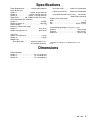
Dimensions
Turbine Diameter
System 7 . . . . . . . . . . . . . . . . . . . . . . . 5.7 in (144.78 mm)
System 9 . . . . . . . . . . . . . . . . . . . . . . . 7.2 in (182.88 mm)
System 12 . . . . . . . . . . . . . . . . . . . . . . 7.2 in (182.88 mm)
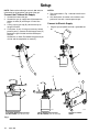
Setup
NOTE: Refer to the turbine gun manual, 308–336, for
information on the operation and setup of the gun.
Connect the Fluid and Air Supply
1. Connect the hose to the gun.
2. Connect the gun air supply hose (A) between the
turbine air outlet (D) and the gun air inlet. See
Fig. 1.
3. If using a spray gun cup (B), connect the cup to
the gun fluid inlet.
4. For System 12 only: If using an accessory remote
pressure pot (C), connect the fluid supply hose (G)
between the gun fluid inlet and the remote pressure pot.
Connect the air hose (E) between the pressure pot
air inlet and the compressor air outlet (F).
NOTES:
The circled letters in Fig. 1 indicate hose line connections.
Only the System 12 turbine units include a compressor for use with a remote pressure pot.
Connect to Electric Supply
1. Plug the sprayer power cord into a grounded outlet.
B
A
G
A
B
Z
X
X
E
E
F
Y
G
G
Y
Z
Z
C
C
02859
2-1/2 Gallon Remote Pressure Pot
Part No. M70604 (see Accessories)
Fig. 1
Y
2 Quart Remote Pressure Pot
Part No. M70585 (see Accessories)
D X
System 12 Turbine
shown
03074
Setup
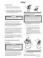
Prepare the Fluid
1. Always strain the fluid before spraying; this
includes color, reducer and hardeners if used.
2. When using a turbine spray system, you need to
use a slower drying reducer or thinner to compensate for the faster drying time caused by the warm
air of the turbine. Do not over reduce.
J
H
02845
Fig. 2
Accessory Remote Pressure Pot
CAUTION
The performance of the turbine sprayer will vary
with the viscosity of the material. Unnecessary hose
length will cause the air pressure to drop.
WARNING
The remote pressure pots remain pressurized until
pressure is manually relieved. To reduce the risk of
serious injury from pressurized fluid or accidental
spray from the gun, always relieve pressure in the
pressure pot before loosening or removing the cover.
Paint Reduction – Automotive Type Finishes
Reduce and catalyze all paint to manufacturer’s specifications. To compensate for the faster drying time of
turbine systems, use a reducer one-step slower than
what is used for conventional air spray.
Paint Reduction – Industrial or Domestic Coatings
Reduce and catalyze all paint to manufacturer’s specifications. If no reductions are given, first thoroughly
mix the fluid to be sprayed. Then gradually mix in the
proper reducer, testing the fluid until you have the correct spraying consistency.
1. Relieve the remote pressure pot pressure by following these steps:
a. Turn off the air supply to the pressure pot.
b. 2 1/2 Gallon Remote Pot: Pull the pressure
relief valve ring (205) until pressure is completely relieved.
2 Quart Remote Pot: Turn out the pressure
relief knob (113) about one turn. Wait until
pressure is completely relieved before removing the cover. Close the knob before using the
system again.
See Fig. 3.
To test the consistency: Remove the stir stick from the
thinned paint. When the paint stream running off the
stir stick breaks into droplets, the first few drops should
be about one second apart.
Fill the Cup or Remote Pressure Pot
113
Spray Gun Cup
WARNING
205
The spray gun cup is pressurized by the gun’s air
supply. To reduce the risk of serious injury from
pressurized fluid or accidental spray from the gun,
always turn off the air supply to the gun before removing the spray gun cup.
2 1/2 gallon
Fig. 3
Only fill the cup 3/4 full to help keep the fluid tube
clean, then install the cover. The under-cup cover has
a latch (H) to secure it to the cup. The over-cup has a
ring with notches (J) that secures the cup hood into
place when locked in place on the cup.
2 quart
02860
02882
2. Remove the pressure pot cover and fill the pressure pot. Secure the cover.
NOTE: 2 quart remote pressure pot only: lightly coat
the cover threads with petroleum jelly.
820-205 Setup
CAUTION
If the 2 quart remote pressure pot is accidentally
tipped over or held at too great of an angle, fluid
may leak into the air regulator. Take precautions to
avoid this. If fluid does get into the regulator, clean
it immediately.
1. Turn the turbine on a few minutes before you start
spraying to allow for warm-up time.
NOTE: When the turbine is not in use for an extended
period of time, turn it off. The turbine does not shut off
automatically.
CAUTION
Do not tighten the pressure pot cover more than
hand-tight. Excessive tightening may damage the
cover gasket.
2. Be sure the turbine filter is clean before operating.
See Maintenance to check and clean the filter.
Prepare the Surface to be Sprayed
NOTE: To adjust the spray gun pattern, see the turbine gun manual 308–336.
To achieve proper adhesion, make sure the surface to
be sprayed is completely clean.
System 12 Cold Weather Operation
Operating the Turbine
WARNING
Sparking can be expected in the normal operation
of the turbine motor. Sparks could ignite fumes
from flammable liquid, dust particles and other
flammable substances in the spray area, and
cause serious injury and property damage. Be sure
to follow the precautions below:
When flammable liquid is sprayed or used for
flushing or cleaning equipment, the turbine must
be placed at least 20 feet (6.1 m) away from
areas where hazardous concentrations of flammable vapors are likely to occur.
Use additional air hose if necessary to ensure
that the turbine is operated in a clean, dry, well
ventilated area.
Never place the turbine inside a spray booth!
Use this equipment outdoors or in extremely
well ventilated areas.
Avoid all ignition sources such as static electricity from plastic drop cloths, open flames such as
pilot lights, hot objects such as cigarettes, arcs
from connecting or disconnecting power cords
or turning light switches on and off. Extinguish
or remove all sources of ignition.
The System 12 has a diaphragm compressor. When
the compressor is new, the diaphragm will become stiff
in cold weather. If cold enough, the stiff diaphragm will
not allow the compressor to start (the unit will hum). If
this occurs, follow these steps:
1. Turn the turbine and compressor off.
2. Unplug the turbine from the power source.
3. Loosen the four main filter screws and remove the
filter; replace the main filter and pre-filter if they
are dirty.
4. Hand spin the cooling fan on the compressor for a
few revolutions.
5. Reassemble the turbine.
6. Plug in the turbine and turn the compressor on.
The compressor should start.
Shutdown
WARNING
The 2 qt gun cups and accessory remote pressure
pots remain pressurized until pressure is manually
relieved. To reduce the risk of serious injury from
pressurized fluid or accidental spray from the gun,
always relieve pressure in the cup or pressure pot
before checking or servicing any part of the spray
System ; before installing, cleaning or changing
fluid nozzles; before loosening or removing the accessory remote pressure pot cover; and whenever
you stop spraying.
113
205
1. When spraying is finished, turn off the air supply to
the gun.
2 1/2 gallon
2 quart
2. If using a remote pressure pot, relieve its pressure
by following these steps:
a. Turn off the air supply to the pressure pot.
b. 2 1/2 Gallon Remote Pot: Pull the pressure
relief valve ring (205) until pressure is completely relieved.
2 Quart Remote Pot: Turn out the pressure
relief knob (113) about one turn. Wait until
pressure is completely relieved before removing the cover. Close the knob before using the
system again.
See Fig. 4.
Fig. 4
02860
02882
NOTE: Elevate the spray gun and pull the trigger. This
will allow the fluid in the fluid hose to drain back into
the remote pressure pot.
3. If using a spray gun cup, unlatch the cup cover
and loosen or remove the cup from the cover to
relieve the cup pressure.
4. Clean the spray gun and cup as instructed in the
turbine gun manual, 308–336.
820-205
Maintenance
Daily
CAUTION
Check the main turbine filter daily for cleanliness.
Do not operate the turbine sprayer without the filter
installed.
The turbine systems are lifetime lubricated. The only
maintenance required is filter cleaning and replacement.
The turbine main filter and pre-filter must be clean at
all times to provide sufficient air flow to cool the motor
and atomize the fluid. Check the filters weekly, minimum. Replace the pre-filter as required.
Main
filter
screws
NOTE: To check the filter, turn on the turbine and
place a piece of paper against the air intake filter. If the
air intake holds the paper in place, the filter is okay.
To clean the main filter:
1. Turn off and unplug the turbine.
2. Loosen the four main filter screws. See Fig. 5.
3. Remove the main filter and clean it by following
one of the following three methods:
Tap the filter gently on a flat surface, dirty side
down.
Direct compressed air (100 psi [7 bar] maximum) through the filter panel in the opposite
direction of the arrows on the side of the filter.
Soak the filter for 15 minutes in water and a
mild detergent. Rinse the filter until it is clean.
Air dry the filter; do not use compressed air.
WARNING
To avoid damage to the turbine and possible electric shock, never install a damp filter in the turbine.
Fig. 5
System 12 Turbine shown
03079
Weekly
1. Check the hose for cracks, leaks, and holes. Replace, if necessary.
Annually or 600 Hours (whichever comes
first)
1. Replace the motor brushes 600 hours after turbine
sprayer operation. If the brushes are not replaced,
motor failure will occur.
NOTE: It is recommended that an authorized service
center perform the motor brush replacement. See the
procedure on page 13.
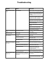
Troubleshooting
PROBLEM
Remote Container Pressurization
CAUSE
No fluid delivery.
SOLUTION
Check for leaks at the container gasket,
2 quart lid, and 2 1/2 gal pot wing nuts.
Check for air flow from male quick–disconnect at compressor outlet (approx.
1/4 CFM).
Turn pressure regulator clockwise. Look
for pressure on gauge. (If no pressure on
gauge, check air line and fittings).
Check hole in tank lid under regulator or
needle valve 2 Qt lid. Clean if necessary.
Check for obstructions.
Check if fluid pickup tube is unplugged.
Tighten.
Blow out and clear material hose.
Check container for material.
(System 12) Compressor fails Cold weather operation.
to start
See Cold W eather Operation instructions, page 8.
Turbine fails to start
Power supply.
Cycle red rocker switch.
Poor atomization
Dirty filter.
Clean filter.
Extension cord too long.
Replace with shorter extension cord (do
not exceed 100 ft).
Hose length too long.
Replace with shorter hose. See Accessories for shorter hose and P/N.
Check filter.
Clean filter and replace as necessary.
Excessive high ambient temperature.
Move turbine to cooler area.
Excessive brush wear.
Remove turbine wrapper and:
. Check for free motor rotation,
. Check brush wear,
. Replace motor brushes if necessary.
Excessive current draw.
Return to authorized service center.
Hot and humid weather can generate
temperatures that make gun handle uncomfortable.
Extra hose is recommended in warmer
environments.
Red Rocker Circuit Breaker
Switch Trips
Spray gun handle is uncomfortably warm.
Install handle insulator (provided
with
gun).
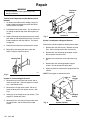
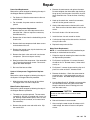
Repair
WARNING
Top Cover
Screws
Turn off turbine and unplug power for the following procedures.
Turbine Switch Replacement (Red Rocker Circuit
Breaker)
1. To remove the turbine switch, wedge a large flat
blade screwdriver between the top of the switch
and the turbine face plate.
2. Push down firmly on the switch. Pry the switch out
far enough so the two top switch locking tabs are
visible.
3. While maintaining outward pressure on the switch,
push down on the two locking tabs with a small flat
blade screwdriver until they release. The switch
will pop out.
4. Disconnect the two wires and remove the switch.
5. Reinstall by connecting the wires to the new
switch. Snap the switch into place.
Front Screws
Fig. 7
System 12
03074
System 7 and System 9 Wrapper Removal
Remove the cabinet wrapper by following these steps.
1. Remove the four filter screws. Remove the main
filter. Clean and replace the filter if necessary.
2. Remove the four remaining top wrapper screws.
Do not remove handle screws.
3. Remove one screw from each side of the wrapper.
Locking Tabs
4. Remove the four remaining bottom wrapper
screws. Do not remove the rubber feet.
5. Gently pry loose and remove the wrapper from the
cabinet.
Fig. 6
03728
NOTE: The wrapper is sealed with caulk.
Filter
Screws
System 12 Turbine Wrapper Removal
1. Remove the four main filter stop screws and remove the main filter. (Clean or replace as necessary. See Maintenance.)
2. Remove the nine top cover screws. Do not remove the three paint tank retainer screws. See
Fig. 7.
Wrapper
Screws
3. Gently pry up on the top cover and remove. (The
wrapper is sealed with caulk.)
4. Remove the four 1/4 x 20 pan head screws from
the cabinet front. Do not remove the handle
screws.
Fig. 8
Side
Screws
System 9 shown
03067
Repair
Power Cord Replacement
Remove the cabinet wrapper by following the steps in
the Wrapper Removal procedure.
1. For System 12: Slide the motor mount to the rear
of the cabinet.
2. For all models, the power cord can now be replaced.
System 12 Compressor Replacement
1. Remove the four main filter stop screws and remove the filter. (Clean or replace as necessary.
See Maintenance.)
2. Remove the air hose from the barbed fitting on the
check valve.
3. Remove the motor mount and replace the motor.
Do not overtighten the three rubber stop bushings.
Snug up only until the motor is held firmly in place.
Apply removable Loc–Tite to the three mounting
nuts.
4. Hook up the switch wire, neutral butt connector,
and Loc–tite the ground screw nut.
5. Gently slide motor mount to the front of the cabinet. Make sure the side foam doesn’t catch on the
mount.
6. Re–install the four 1/4 x 20 front screws
7. Install the foam fan seal around fan intake.
8. Caulk the top flange of the cabinet with a fine bead
of acrylic latex caulk.
3. Remove the three compressor hold–down screws
on the bottom of the unit.
9. Replace the top and main filter.
4. Remove the ground screw, clip the lead wires, and
remove the compressor.
Motor Brush Replacement
NOTE: It is recommended that this procedure be performed by an authorized service center.
5. Remove the check valve and install it on the new
compressor. (Do not use tape or sealant)
1. Follow the steps for removing the motor in the Motor Replacement procedure.
6. Rewire and install the compressor. Use removable
Loc–Tite on the compressor screws. Do not overtighten the rubber bumpers.
2. For System 9 and System 12, remove the metal
shroud on the 7.2” diameter motor (1 sheet metal
screw), or...
7. Re–install the hose and filter.
3. For System 7, remove the two retaining clips and
plastic fan cover on the 5.7” diameter motor.
System 12 Compressor Toggle Switch Replacement
Remove the cabinet wrapper by following the steps in
the System 12 Wrapper Removal procedure.
1. Slide the motor mount to the rear of the cabinet.
The toggle switch can now be replaced.
Motor/Turbine Replacement
Remove the cabinet wrapper by following the steps in
the Wrapper Removal procedure.
1. The motor can now be replaced. The new motor
assembly kit, M71515, is supplied with a brass nipple, bushing, rubber bottom spacer, foam fan seal,
ground ring, switch connector, and a neutral wire
butt connector.)
2. Remove the ground screw and switch wire. Clip
the neutral lead.
4. Remove the brushes. Check the commutator for
excessive wear. If the commutator has wear, replace the motor. See Motor Replacement procedure.
5. Use the Motor Brush Kit, M70590, and reassemble
the new motor brushes using the reverse order
Keep the lead wires from all rotating parts and
from the motor frame.
CAUTION
Do not run the motor with the air inlet or outlet
sealed off.
6. Reinstall the motor in reverse order.
7. After running the motor for 30–45 minutes at full–
rated voltage, the motor will return to full performance.
Repair
Motor
Compressor
Black
Black
60
4
6
White
Green
30
Black
7
Rocker
Switch
Green
7
Green
Black
Black
White
79
Green
Black
White
White
Black
Power
Cord
03732
System 7
Fig. 9
Motor
Black
37
4
Green
30
Black
4
6
7
Rocker
Switch
Green
Black
White
System 9
Fig. 10
Motor
Motor
61
37
4
Green
Toggle
Rocker
Switch
Switch
Power
Cord
03735
Black
Fig. 11
System 12
Black
Power
Cord
03734
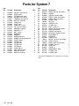
Parts for System 7
38
31
39
80
26
30
29
35
34
28
83
33
20
11
43
27
60
61
3
42
54
53
6
62
5
7 8
4
16
45
24
25
26
18
17
9
88
10
85
86
84
87
03069
Motor
37
4
Black
30
Green
7
Black/White
6
White
4
Green
Black
Rocker
Switch
Power
Cord
03732
Parts for System 7
Ref
No.
Part No.
Description
3
4
5
6
7
8
9
10
11
13
16
17
18
20
24
25
26
27
28
29
30
31
33
34
35
36
M70656
M70601
106013
M70759
112605
M70760
M71153
M70836
M70753
M71179
M70761
M70773
M70772
M70834
M70763
M70775
M70774
M70835
M70859
M70757
M70609
M70607
M71384
M70872
M70874
M70933
SWITCH, rocker 8 amp
CORD, power
FITTING, strain relief
CONNECTOR, red butt
TERMINAL, ground ring
SWITCH, connector
FOAM, strip
PLATE, face
FOAM, die cut 109
TIE, wire (not shown)
BUSHING, stepped
WASHER, 1/4
NUT, 1/4–20
WRAPPER
BUMPER
SCREW, 832x5/8
SCREW, black oxide 832x1/2
PLATE, bottom
FILTER, stop
FILTER, foam
FILTER, main
FILTER, pre
FOAM, die cut
NUT, cabinet handle
WASHER, 3/16x1
DECAL (not shown)
Qty
Ref
No.
Part No.
Description
1
1
1
1
1
1
2
1
2
1
3
6
3
1
4
4
16
1
1
3
1
1
2
2
2
1
37
38
39
40
41
42
43
45
53
54
56
60
61
62
66
71
73
75
80
82
83
84
85
86
87
88
M70783
M70870
M70873
M70782
M70785
M70959
100284
M70779
M70764
M70770
M71138
M71184
M71185
M70989*
M70756
070514
M71385
728677
M71188
186620
M71398
M71519
M70397
M70402
M71412
M71246
LABEL, warning (not shown)
HANDLE,
SCREW, cabinet handle
LABEL, caution (not shown)
LABEL, USA (not shown)
MOUNT, motor
NUT, hex
SPACER, 2.312
O–RING, ring
BOLT 1/–20x L/2
DECAL, S/N set (not shown)
WIRE, green/yellow
SCREW, self–tapping
MOTOR Kit, System 7/120V
DOUGHNUT, 6”
ADHESIVE
FOAM, die cut
DECAL, city of LA (not shown)
STRIPS, Velcro
LABEL, ground (not shown)
GASKET, fan seal
HOSE, 20 ft
VALVE, air
DISCONNECT, quick
O–RING, valve
O–RING, hose
Qty
1
1
2
1
1
1
2
3
3
3
1
1
1
1
1
2
1
.5
1
1
1
1
1
1
1
* Motor Brush Kit M70590 is also available. Purchase separately.
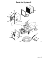
Parts for System 9
38
31
39
80
26
30
80
29
28
35
31
83
33
20
11
43
27
42
3
6
62
5
4
24
25
7 8
9
45
54
53
16
18
17
26
87
88
85
86
10
84
03071
Parts for System 9
Motor
Black
37
4
Green
30
Black
4
6
7
Rocker
Switch
Green
Black
White
System 9
Power
Cord
03735
Parts for System 9
Ref
No.
Part No.
Description
3
4
5
6
7
8
9
10
11
13
15
16
17
18
20
24
25
26
27
28
29
30
31
33
34
35
36
37
38
39
40
41
42
43
44
45
53
54
56
62
M70657
M70601
106013
M70759
112605
M70760
M71153
M71112
M70753
M71179
M71190
M70761
M70773
M70772
M70834
M70763
M70775
M70774
M70835
M70859
M70757
M70609
M70607
M71384
M70872
M70874
M70933
M70783
M70870
M70873
M70782
M70785
M70864
100284
M70789
M70778
M70764
M70770
M71194
M71515*
SWITCH, rocker 12 amp
1
CORD, power
1
FITTING, strain relief
1
CONNECTOR, red butt
1
TERMINAL RING, ground
6
SWITCH, connector
1
STRIP, foam
2
PLATE, face
1
FOAM, die cut
2
WIRE, tie (not shown)
1
CONNECTOR, butt (not shown) 1
BUSHING, stepped
3
WASHER, 1/4
6
NUT, 1/–20
3
WRAPPER
1
BUMPER
4
SCREW, 8322x5/8
4
SCREW, black oxide 832x1/2
12
PLATE, bottom
1
FILTER, stop
1
FOAM. filter
3
FILTER, main
1
FILTER, pre
1
FOAM, die cut
2
NUT, cabinet handle
2
WASHER, 3/16x1
2
DECAL (not shown)
1
LABEL, warning (not shown)
1
HANDLE
1
SCREW, cabinet handle
2
LABEL, caution (not shown)
1
LABEL, USA (not shown)
1
MOUNT, 2 stage
1
NUT, hex
2
SCREW, 1/4 x 20 x 3/4
4
SPACER, 1.812
3
RING, o–ring
3
BOLT, 1/4–20x3 L/2
3
DECAL, S/N Set (not shown)
1
*MOTOR, Kit
1
Qty
Ref
No.
Part No.
Description
75
82
83
84
85
86
87
88
728677
186620
M71362
M71519
M70397
M70402
M71412
M71246
DECAL, city of LA (not shown)
LABEL, ground (not shown)
GASKET, fan seal
HOSE, 20 ft
VALVE, air
DISCONNECT, quick
O–RING, valve
O–RING, hose
Qty
1
1
1
1
1
1
1
1
* Motor Brush Kit M70590 is also available. Purchase separately.
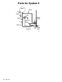
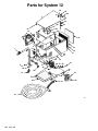
Parts for System 12
66
65
64
64
62
90
63
39
44
51
35
4
9
34
8
1
14
12
11
13
21
26
9
83
4
45
36
58 59 60
61
29
32
15
24
38
37
16
10
23
33
31
22
27
30
92
28
91
03077
Compressor
Toggle
Rocker
Switch
Switch
Motor
Motor
61
Black
60
White
Green
Green
Black
White
79
Green
Black
White
Black
Black
System 12
Black
Power
Cord
03734
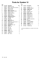
Parts for System 12
Ref
No.
Part No.
Description
1
3
4
5
6
7
8
9
10
11
12
13
14
15
16
20
21
22
23
24
25
26
27
28
29
31
32
33
34
35
36
M70739
M70814
M70603
M70811
M71242
M70815
M70657
M70789
M70601
102799
M70760
M70759
106013
M70740
M71303
728677
M71180
M70744
M71304
M70927
M71137
M70763
M70747
M70748
M70749
M70757
M70746
M70609
M71188
M70607
M70772
HANDLE, with grip
1
DECAL, compressor (not shown) 1
SWITCH, toggle
1
SWITCH, plate
1
DECAL (not shown)
1
LABEL, turbine (not shown)
1
SWITCH, rocker
1
SCREW, 1/4x20x3/4
4
CORD, power
1
CABLE, terminal
2
SWITCH, connector
2
CONNECTOR, red butt
1
GROMMET, cord
1
CASTER
1
WRAPPER
1
LABEL (not shown)
1
WIRE, white
1
SCREW, black oxide 8–32x1/2 22
FOAM, top/bottom
2
BASE, bottom
1
COMPRESSOR, 110V
1
BUMPER
3
WHEEL, 6 in
2
CAP, hub
2
PIN, cotter
2
FOAM, filter
3
AXLE
1
FILTER, main
1
VELCRO, strips
.5
FILTER, pre
1
NUT, 1/4–20
3
Qty
Ref
No.
Part No.
Description
37
38
39
44
45
47
50
51
52
58
59
60
61
62
63
64
65
66
83
90
91
92
M70773
M70761
M70753
M70745
100284
M70778
M70764
M70769
M71515
M70955
M70736
M70804
M71192
M70809
M71305
M71136
M70805
M70673
M70741
M71362
M71519
M71246
WASHER, 1/4
BUSHING, stepped
FOAM, die cut
MOUNT, motor
NUT, keps
SPACER, 1.812
RING, 0–ring
BOLT, 1/4–20x3
*MOTOR, Kit
ELBOW, 1/4 pipe
VALVE, relief
FITTING, barbed
HOSE, 8”
FITTING, barbed hose
LID
WASHER
ELBOW, 90degree
PLUG, female QD
SOCKET
GASKET, fan seal
HOSE, 20 ft
O–RING, hose
Qty
* Motor Brush Kit M70590 is also available. Purchase separately.
6
3
2
1
1
3
3
3
1
1
1
1
1
1
1
3
1
1
1
1
1
1
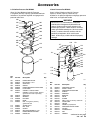
Accessories
2-1/2 Gallon Pressure Pot M70604
2 Quart Pressure Pot M70962
50 psi (3.5 bar) Maximum Inlet Air Pressure
2-1/2 gallon (9.5 liter) capacity, galvanized steel tank.
Includes an air pressure regulator and gauge and a
pressure relief valve.
216
50 psi (3.5 bar) Maximum Inlet Air Pressure
2 quart (1.94 liter) capacity, aluminum cup.
Includes an air pressure regulator and gauge, pressure
relief valve, and rigid hook handle.
218
201
217
208
202
209
215
203
WARNING
Do not use 1,1,1-trichloroethane, methylene
chloride, other halogenated hydrocarbon solvents or fluids containing such solvents in the
turbine spray System , which contains aluminum
and/or galvanized-coated parts. Such use could
result in a serious chemical reaction, with the
possibility of explosion, which could cause
death, serious injury, and/or substantial property
damage.
210
204
207
205
206
214
102
117
122
126
127
211
213
118
103
116
115
121
114
212
120
110
125
124
02861
Ref.
No.
Part No.
Description
201
202
203
204
205
206
207
M70670
M70674
M70687
M70676
M70686
M70685
M70616
M70617
208
209
210
211
212
M70678
M70677
M70680
M70684
M70683
213
214
215
216
217
218
M70681
M70682
M70688
M70675
M70671
M70805
PRESSURE GAUGE
HEX NIPPLE, 1/4 in.
COUPLING
O-RING
PRESSURE RELIEF VALVE RING
FLUID TUBE
GASKET, standard; EPDM
GASKET, solvent resistant; Thiokal
(optional–must order separately)
WING NUT
WASHER
EYE BOLT
BAND
POT, 2-1/2 gallon (9.5 liter),
galvanized steel
SCREW, band
NUT, band
COVER
QUICK DISCONNECT, male
PRESSURE REGULATOR
ELBOW, 90_
119
112
101
105
128
113
111
107
104
106
108
109
123
Qty.
1
1
1
1
1
1
1
1
5
5
5
5
1
5
5
1
1
1
1
02951
Ref.
No.
Part No.
Description
101
102
103
104
105
106
107
108
109
110
111
112
113
114
115
116
117
M70670
M70727
M70671
M70731
M70895
M70733
M70734
M70735
M70730
M70729
M70728
M70628
M70726
M70725
M70724
M70723
M70722
PRESSURE GAUGE
SAFETY VALVE
PRESSURE REGULATOR
SPRING
REDUCER
BRACKET
VALVE
SCREW
POT, 2 quart (1.94 liter), aluminum
FLUID TUBE
COVER
GASKET, polyethylene
PRESSURE RELIEF KNOB
FITTING
FLUID OUTLET
NUT
HANDLE
Qty.
1
1
1
1
1
1
1
1
1
1
1
1
1
1
1
1
1
continued on next page
820-205 Accessories
118
119
120
121
122
123
124
125
126
127
128
M70675
M70805
M71491
M71470
M70854
M70402
M70397
M71412
M70399
M71246
M72842
PLUG, male, quick disconnect
ELBOW, 90_
HOSE, fluid; 5 ft. (1.5 m) long;
1/4 in. (6.35 mm) ID
HOSE, air; 4.5 ft. (1.4 m) long
HOSE CLAMP
QUICK DISCONNECT, female
AIR CONTROL VALVE
O-RING, air valve
QUICK DISCONNECT, male
O–RING, hose
FITTING, air pressure stem
1
1
1
1
1
1
1
1
1
1
1
NOTE: See selection charts in the gun turbine manual,
308–336, to order fluid sets.
Lubricant 111–265
One 4 oz. (113 gram) tube sanitary (non-silicone)
lubricant for fluid seals and wear areas.
#4 Ford Viscosity Cup M70702
Part No.
Description
M70562
M70582
M70425
M70464
M70395
–
1.0 mm Fluid Set
2.0 mm Fluid Set
1 Quart Under-cup Gaskets
Fluid Strainer
Upper Air Pressure Hose
Parts Box with Compartments
Automotive User Kit M70705
For use with automotive finishes.
Part No.
Description
M70559
M70647
M70425
M70464
M70395
–
1.0/0.05 mm Fluid Set
1.2/0.7 mm Fluid Set
1 Quart Under-cup Gaskets
Fluid Strainer
Upper Air Pressure Hose
Parts Box with Compartments
1 Quart Cup Lid M70610
Trail Around Dolly M70700
Lightweight and mobile platform with wheels, for use
with smaller units.
Fits on cup part no. M70423 for air tight storage of
fluid.
Includes:
To measure viscosity of fluid.
1 Quart Cup and Lid Assembly M70425
1 quart under-cup with air tight lid.
1 Quart Cup Gaskets M70427
5 pack of polyethylene gaskets for use with 1 quart
under-cup.
3/4 Liter Cup and Lid Assembly M71047
3/4 liter over-cup with lid.
3/4 Liter Cup Gaskets M71027
5 pack of polyethylene gaskets for use with 3/4 liter
over-cup.
Cup Check Valve M71007
To help prevent the cup from depressurizing after the
air is shut off.
Fluid Strainer M70464
Install on the end of the cup or pressure pot fluid tube
to strain the fluid and help eliminate surface blemishes
and plugged tips. 100 mesh screen.
Blow Gun M70703
For dusting and drying. With quick disconnect.
Contractor User Kit M70704
Used for fine finish materials and heavier bodied materials (latex).
Includes:
Part No.
Description
M70852
M70853
M71434
M70889
100–086
Swivel Caster
Rigid Caster
Dolly Plate
3/4 Pop Rivet
Plain #10 Washer
Air Control Valve M70398
Includes:
Part No.
M71549
M71412
Description
Air Valve
O–ring
System 12 Unload Valve M70691
System 7 Motor Assembly Kit M71514
System 9 Motor Assembly Kit M71515
System 12 Compressor Kit M71537
System 12 Conversion Kit M71513
Motor Brush Kit M70590
45 Degree Elbow M70593
Prefilter 12–Pak M70609
System 9 Y Fitting Kit M70611
5 Pak Tank Liner M70695
2 Qt. Gasket, 5 Pak M7425
Accessories
Main Filter with Velcro Strips M71558
3/8 in. id Paint Fluid Hose
25 ft
M71481
15 ft
M71482
30 ft
M71484
50 ft
M71485
40 ft
M71486
Notes
Notes
The SHERWIN–WILLIAMS Warranty
and Disclaimers
WARRANTY
Graco warrants all equipment manufactured by it and bearing its name to be free from defects in material and workmanship on
the date of sale by an authorized Graco distributor to the original purchaser for use. As purchaser’s sole remedy for breach of this
warranty, Graco will, for a period of twelve months from the date of sale, repair or replace any part of the equipment proven defective. This warranty applies only when the equipment is installed, operated and maintained in accordance with Graco’s written recommendations.
This warranty does not cover, and Graco shall not be liable for, any malfunction, damage or wear caused by faulty installation,
misapplication, abrasion, corrosion, inadequate or improper maintenance, negligence, accident, tampering, or substitution of
non–Graco component parts. Nor shall Graco be liable for malfunction, damage or wear caused by the incompatibility with Graco
equipment of structures, accessories, equipment or materials not supplied by Graco, or the improper design, manufacture, installation, operation or maintenance of structures, accessories, equipment or materials not supplied by Graco.
This warranty is conditioned upon the prepaid return of the equipment claimed to be defective to an authorized Graco distributor
for verification of the claim. If the claimed defect is verified, Graco will repair or replace free of charge any defective parts. The
equipment will be returned to the original purchaser transportation prepaid. If inspection of the equipment does not disclose any
defect in material or workmanship, repairs will be made at a reasonable charge, which charges may include the costs of parts,
labor and transportation.
DISCLAIMERS AND LIMITATIONS
The terms of this warranty constitute purchaser’s sole and exclusive remedy and are in lieu of any other warranties (express or
implied), including warranty of merchantability or warranty of fitness for a particular purpose, and of any non–contractual
liabilities, including product liabilities, based on negligence or strict liability. Every form of liability for direct, special or consequential damages or loss is expressly excluded and denied. In no case shall Graco’s liability exceed the amount of the purchase price.
Any action for breach of warranty must be brought within two (2) years of the date of sale.
EQUIPMENT NOT COVERED BY GRACO WARRANTY
Graco makes no warranty, and disclaims all implied warranties of merchantability and fitness for a particular purpose, with
respect to accessories, equipment, materials, or components sold but not manufactured by Graco. These items sold, but not
manufactured by Graco (such as electric motor, switches, hose, etc.) are subject to the warranty, if any, of their manufacturer.
Graco will provide purchaser with reasonable assistance in making any claim for breach of these warranties.
Phone Numbers
TO PLACE AN ORDER, contact your Graco distributor, or call this number to identify the distributor
closest to you: 1–800–328–0211 Toll Free
FOR TECHNICAL ASSISTANCE, service repair
information or assistance regarding the application of
Graco equipment: 1–800–543–0339 Toll Free
The SHERWIN–WILLIAMS COMPANY, 101 PROSPECT AVENUE, CLEVELAND, OHIO 44115
PRINTED IN U.S.A.
802–205 6/94 Revised 7/94