1
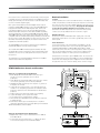
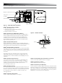
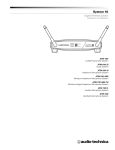
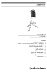
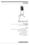
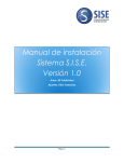
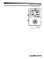
System 10 Stompbox
Digital Wireless System
Installation and Operation
ATW-1501
Stompbox Wireless System
2
System 10 Stompbox Installation and Operation
CAUTION
RISK OF ELECTRIC SHOCK
DO NOT OPEN
WARNING: TO REDUCE THE RISK OF FIRE OR ELECTRIC SHOCK, DO
NOT REMOVE SCREWS. NO USER-SERVICEABLE PARTS INSIDE.
REFER SERVICING TO QUALIFIED SERVICE PERSONNEL.
WARNING: TO REDUCE THE RISK OF FIRE OR ELECTRIC SHOCK, DO
NOT EXPOSE THE APPLIANCE TO RAIN OR MOISTURE.
CERTIFICATION: THIS DEVICE COMPLIES WITH PART 15 OF THE FCC
RULES. THIS DEVICE COMPLIES WITH INDUSTRY CANADA LICENSEEXEMPT RSS STANDARD(S). OPERATION IS SUBJECT TO THE
FOLLOWING TWO CONDITIONS: (1) THIS DEVICE MAY NOT CAUSE
HARMFUL INTERFERENCE, AND (2) THIS DEVICE MUST ACCEPT ANY
INTERFERENCE RECEIVED, INCLUDING INTERFERENCE THAT MAY
CAUSE UNDESIRED OPERATION.
Cet appareil est conforme à la/aux norme(s) RSS exempte(s) de licence
d’Industrie Canada. Son fonctionnement est soumis aux deux conditions
suivantes : (1) cet appareil ne doit pas causer d’interférence et (2)
cet appareil doit accepter toutes les interférences, y compris celles
susceptibles de provoquer un fonctionnement non souhaité.
WARNING: Changes or modifications not expressly approved in writing
by Audio-Technica may void the user’s authority to operate
this equipment.
RF Exposure Statement: This transmitter must not be co-located or
operated in conjunction with any other antenna or transmitter.
This equipment complies with FCC/IC radiation exposure limits set
forth for an uncontrolled environment and meets the FCC radio
frequency (RF) Exposure Guidelines and RSS-102 of the IC radio
frequency (RF) Exposure rules. This equipment has very low levels
of RF energy that it deemed to comply without maximum permissive
exposure evaluation (MPE). But it is desirable that it should be installed
and operated keeping the radiator at least 20cm or more away from
person’s body.
Cet équipement est conforme aux limites d’exposition aux
rayonnements énoncées pour un environnement non contrôlé et
respecte les règles d’exposition aux fréquences radioélectriques (RF)
CNR-102 de l’IC. Cet équipement émet une énergie RF très faible qui
est considérée conforme sans évaluation de l ’exposition maximale
autorisée. Cependant, il est souhaitable qu'il devrait être installé et
utilisé en gardant une distance de 20 cm ou plus entre le dispositif
rayonnant et le corps.
Note: This equipment has been tested and found to comply with
the limits for a Class B digital device, pursuant to part 15 of the FCC
Rules. These limits are designed to provide reasonable protection
against harmful interference in a residential installation. This equipment
generates, uses and can radiate radio frequency energy and, if not
installed and used in accordance with the instructions, may cause
harmful interference to radio communications. However, there is no
guarantee that interference will not occur in a particular installation. If
this equipment does cause harmful interference to radio or television
reception, which can be determined by turning the equipment off and
on, the user is encouraged to try to correct the interference by one or
more of the following measures:
-Reorient or relocate the receiving antenna.
-Increase the separation between the equipment and receiver.
-Connect the equipment into an outlet on a circuit different from that
to which the receiver is connected.
-Consult the dealer or an experienced radio/TV technician for help.
This Class B digital apparatus complies with Canadian ICES-003.
Cet appareil numerique de la classe B est conforme a la norme
NMB-003 du Canada.
CAUTION! Electrical shock can result from removal of the receiver
cover. Refer servicing to qualified service personnel. No userserviceable
parts inside. Do not expose to rain or moisture. The circuits inside the
receiver and transmitter have been precisely adjusted for optimum
performance and compliance with federal regulations. Do not attempt
to open the receiver or transmitter. To do so will void the warranty, and
may cause improper operation.
Notice to individuals with implanted cardiac pacemakers or AICD
devices: Any source of RF (radio frequency) energy may interfere with
normal functioning of the implanted device. All wireless microphones
have low-power transmitters (less than 0.05 watts output) which are
unlikely to cause difficulty, especially if they are at least a few inches
away. However, since a “body-pack” mic transmitter typically is placed
against the body, we suggest attaching it at the belt, rather than in
a shirt pocket where it may be immediately adjacent to the medical
device. Note also that any medical-device disruption will cease when
the RF transmitting source is turned off. Please contact your physician
or medical-device provider if you have any questions, or experience any
problems with the use of this or any other RF equipment.
Important Safety Instructions
1. Read these instructions.
2. Keep these instructions.
3. Heed all warnings.
4. Follow all instructions.
5. Do not use this apparatus near water.
6. Clean only with a dry cloth.
7. Install in accordance with the manufacturer’s instructions.
8. Do not install near any heat sources such as radiators, heat
registers, stoves, or other apparatus (including amplifiers) that
produce heat.
9. Unplug this apparatus during lightning storms or when unused
for long periods of time.
10.Refer all servicing to qualified service personnel. Servicing is
required when the apparatus has been damaged in any way,
such as power-supply cord or plug is damaged, liquid has been
spilled or objects have fallen into the apparatus, the apparatus has
been exposed to rain or moisture, does not operate normally,
or has been dropped.
Thank you for choosing an Audio-Technica professional wireless
system. You have joined thousands of other satisfied customers who
have chosen our products because of their quality, performance and
reliability. This wireless microphone system is the successful result of
years of design and manufacturing experience.
Audio-Technica’s System 10 Stompbox is a digital wireless system
designed to provide rock-solid performance along with easy setup and
clear, natural sound quality. Operating in the 2.4 GHz range, far from
TV and DTV interference, System 10 Stompbox offers a small, portable
receiver with foot switch, two switched TRS balanced ¼" outputs and
an output mode selector. The receiver can be paired with up to eight
UniPak® body-pack transmitters, allowing musicians to easily switch
instruments.
System 10 wireless ensures clear communications by providing three
levels of diversity assurance: frequency, time, and space. Frequency
Diversity sends the signal on two dynamically allocated frequencies
3
System 10 Stompbox Installation and Operation
for interference-free communication. Time Diversity sends the signal
in multiple time slots to maximize immunity to multipath interference.
Finally, Space Diversity uses two antennas on each transmitter and
receiver to maximize signal integrity.
Each System 10 Stompbox professional digital wireless system
includes an ATW-R1500 Stompbox receiver, an ATW-T1001 UniPak
body-pack transmitter with an AT-GcW guitar cable, and hook &
loop strips for adding receiver to an effects pedal board. All A-T
Wireless Essentials® microphones and cables, available separately,
are pre-terminated for use with any ATW-T1001 transmitters. Note:
ATW-T1001 transmitters from earlier System 10 models may not be
compatible with the multi-transmitter pairing and battery level indicator
functions of the System 10 Stompbox receiver. However, these older
transmitter models may be shipped to the Audio-Technica Service
Department for firmware updates.
The ATW-R1500 receiver includes a switching power supply that
automatically adapts to changes in mains voltage.
The versatile ATW-T1001 UniPak body-pack transmitter has both
a high-impedance input for instruments, and a low-impedance input
with bias connection for use with dynamic and electret condenser
microphones.
The transmitter uses internal AA batteries and has a Power/Mute
switch and input Trim (level) adjustment.
Receiver Installation
Location
For best operation, the receiver should be at least 3' (1 m) away from
a wall or metal surface to minimize reflections. Keep the receiver away
from noise sources such as other digital equipment, microwave ovens,
as well as away from large metal objects. Keep System 10 Stompbox
receiver 30' (9 m) away from wireless access points. Operating
transmitters should be kept at least 3' (1 m) from receiver, but will
continue to work up to 60' (18 m) from receiver line of sight.
Output Connection
There are two switched TRS balanced ¼" output jacks on the side
panel. Either output can be connected to a guitar amp, a tuner or an
effects pedal.
Power Connection
Connect the DC plug on the included AC power adapter to the DC
power input on the back of the receiver. Then plug the adapter into
a standard 120 Volt 60 Hz or 230 Volt 50 Hz (depending on global
location) AC power outlet. The receiver may also be used in conjunction
with an effects pedal board with a common power supply, but each
output must be “isolated” in order to prevent noise interference.
(Note that the receiver has no power Off/On switch. The receiver will
be energized whenever the power adapter is connected and plugged
into the AC outlet. Unplug the power supply from the AC outlet when
the system is not in use — both for safety, and to conserve energy.)
ATW-R1500 Receiver Controls and Functions
Figure A — Top Panel Controls and Functions
1. Audio Output B: Switched TRS balanced ¼" phone jack.
Can be connected to guitar amp, tuner or effects
pedal input.
2. Audio Output A: Switched TRS balanced ¼" phone jack. Can be connected to guitar amp, tuner or effects pedal input.
3. A/B Output Indicators: Glows green if output is on, glows red
if output is off or muted.
4. System ID Select Switch: Press to cycle through System ID
numbers or to clear pairing. (System ID is an identical number
assigned to a paired receiver and transmitter for identification
purposes.)
5. Pairing Switch: Press and hold to initiate or clear pairing.
6. System ID Display: Shows System ID number.
7. Foot Switch: Press to toggle between outputs.
8. AF Peak Indicator: Only lights when audio distortion is present
at maximum input.
9. Pair Indicator: Glows green to indicate presence of paired
transmitter. Also blinks green to indicate pairing mode activated.
10.Transmitter Battery Power Indicator
3
4
5
6
8
1
9
10
2
7
Figure B — Rear Panel Controls and Functions
1. Output Mode Selector: Use to switch between A or B Mode
and A Mute Mode.
2. Power Input Jack: Universal (center + or -) 9V-12V DC input.
Connect the DC plug from the included AC adapter.
2
1
4
System 10 Stompbox Installation and Operation
Microphone / Instrument Level Control
LR6,AA
Pairing Switch
Screwdriver
System ID Display
Battery Compartment
Figure C — ATW-T1001 UniPak Transmitter
®
UniPak® Transmitter Battery Installation
1. Slide off the battery cover.
2. Carefully insert two fresh AA alkaline batteries,
observing polarity markings.
3. Replace the battery cover (Fig. C).
UniPak® Transmitter Power/Mute/Battery Indicator
After the battery is installed, press and hold the Power/Mute button
until the indicator LED turns green (Fig. D). If the indicator LED does
not light up when the power button is pressed, the batteries are
installed incorrectly or they are dead. The indicator LED will flash to
show low-battery condition. Press and hold the Power/Mute button
again to turn the transmitter off.
UniPak® Transmitter Mute Function
With the transmitter on, a slight touch of the Power/Mute button will
toggle between muted and unmuted operation. Red indicator LED shows
muted operation. Green indicator LED shows unmuted operation.
UniPak® Transmitter Mute Lock Function
Transmitter must be off to activate mute lock. Press and hold the Pairing
Switch and then press and hold the Power/Mute button until transmitter
powers on. Note: There is no dot next to the System ID when mute lock
is activated.
Figure D — UniPak® Transmitter
Power/Mute
Button
Input
Connector
Antenna
Indicator LED
(Power/Mute/Battery)
Transmitter must be off to deactivate mute lock. Press and hold the
Pairing Switch and then press and hold the Power/Mute button until
transmitter powers on. When deactivated, a dot will display next to the
System ID.
UniPak® Transmitter Input Connection
Connect an audio input device (microphone or guitar cable) to the
audio input connector on the top of the transmitter. A number of
Audio-Technica professional microphones and cables are available
separately, pre-terminated with a UniPak® input connector
(see www.audio-technica.com).
UniPak® Transmitter Antenna
The UniPak® transmitter includes a permanently-attached antenna. If
the received signal is marginal, experiment with different transmitter
positions on your body or instrument; or try repositioning the receiver.
Do not attempt to remove, replace or change the length of the
transmitting antenna.
UniPak® Transmitter Pairing Switch
Used to complete pairing sequence. See page 5.
UniPak® Transmitter Microphone/Instrument Level Control
Used to set microphone/instrument level. See page 5.
UniPak® Transmitter Screwdriver
Used to adjust Level Control. See page 5.
UniPak® Transmitter System ID Display
Shows System ID. See page 5. Note: System ID is an identical number
assigned to a paired receiver and transmitter for identification purposes.
When power is applied, the System ID Display on the transmitter glows
bright and then turns off to conserve battery life. To turn the System ID
Display back on, mute and unmute the transmitter.
5
System 10 Stompbox Installation and Operation
System Operation
Turn down the mixer/amplifier level before starting up the wireless
system. Do not switch on the transmitter yet.
Receiver on...
Plug the power supply into an AC power source. The blue System ID
number on the front panel will illuminate.
Transmitter on...
When the transmitter is switched on, the receiver's green pair indicator
will light, and two indicators light on the transmitter: the transmitter
Power / Battery / Mute status indicator will glow green; and the
transmitter blue System ID display will illuminate. The blue System
ID display on the transmitter turns off after 30 seconds to conserve
battery power; the transmitter Power / Battery / Mute status indicator
will remain illuminated, indicating transmitter status.
To re-illuminate System ID display, press the Power / Mute switch.
Note: this will alter the transmitter mute status. A slight touch of the
power switch toggles between muted and unmuted operation.
The transmitter’s Power / Battery / Mute status indicator glows red
when transmitter is muted, or green to indicated unmuted status. In a
low-battery situation, the Power / Battery / Mute status indicator begins
to blink.
The transmitters have a soft-touch power switch. When the switch is
set to “Mute” (red indicator LED), the transmitter produces RF with
no audio signal. When the switch is “On” (green indicator LED) the
transmitter produces both RF and audio. Excessive audio input to the
transmitter will cause the receiver’s red AF Peak indicator to light.
Input Level Adjustment
The transmitter’s input trimmer control is factory-set for use with
guitar. However, you can adjust the input level if need be. To do so,
slide the battery cover off the transmitter and remove the screwdriver
from its clip. Using the screwdriver, gently turn the “LEVEL” all the
way up (clockwise, toward “H”). Check for excessive gain by playing
instrument at typically loud levels while watching the receiver’s Peak
Indicator. If the Peak Indicator does light, turn the “LEVEL” control
slightly counterclockwise until the Peak Indicator no longer lights with
maximum audio input to the transmitter.
CAUTION! The small trimmer control is delicate; use only the supplied
screwdriver. Do not force the trimmer beyond its normal 190° range
of rotation.
Return the screwdriver to its storage clip when not in use.
Setting System ID Number & Pairing your Transmitter and Receiver
Your system has been preconfigured at the factory to operate with no
other pairing setup required; it will work out of the box. That is, your
receiver and transmitter are already a digital pair, and they have been
assigned the same System ID number.
The pairing instructions outlined below will help you change system
ID numbers and pair additional transmitters to the receiver. Note:
ATW-T1001 UniPak transmitters from earlier System 10 models may
not be compatible with the multi-transmitter pairing and battery level
indicator functions of the System 10 Stompbox receiver. However,
these older transmitter models may be shipped to the Audio-Technica
Service Department for firmware updates.
Note: System ID is an identical number assigned to a paired
receiver and transmitter for identification purposes. The System ID
number is not related to transmitting frequency. Due to the dynamic
nature of System 10 automatic frequency selection, the actual
transmitting frequencies may change during power-up or performance.
These frequency changes are seamless and imperceptible to the ear.
Pairing Receiver with Transmitters
Note: Up to eight transmitters may be paired with the receiver.
1. Turn the receiver and first transmitter on.
2. Press the System ID button on the receiver to choose an ID number
from 1 to 8. The receiver’s display will show your new ID and begin
to blink.
3. Within 15 seconds, press and hold the Pair button on the receiver
for about one second. The Pair light will begin to blink green. The
receiver is now in Pair Mode.
Note: If the receiver Pair button is not pressed within 15 seconds,
the system ID number will revert to its previous setting.
4. Open the transmitter and press and hold its Pair button within 30
seconds of entering Pair Mode. The transmitter display will now
show the System ID number you have chosen on the receiver.
The receiver’s Pair light will glow steady, indicating you have
successfully paired your system.
5. To pair an additional transmitter, you must switch off first
transmitter by pressing and holding its Power/Mute button. Turn the
second transmitter on and follow instructions 2-4 above, making
sure to assign a different System ID number to the new transmitter.
6. Repeat for each additional transmitter. Remember to switch off all
transmitters already paired before adding a new one and to use a
unique ID number for each transmitter.
Note: With all transmitters turned off, the receiver’s System ID
Display will cycle through all currently paired ID numbers. Turn on
a transmitter to activate its pairing with the receiver. The receiver
recognizes only one transmitter at a time. That transmitter must
be turned off before the receiver will recognize another paired
transmitter. *If that transmitter is turned off out of range, the
receiver will not recognize another paired transmitter until the
receiver is reset by disconnecting the power supply.
Clearing Individual ID Pairings
1. Press the receiver’s System ID button to select the ID number you
wish to clear. The number will begin to blink.
2. Press and hold the Pair and then ID button for about three seconds,
until the display shows a blinking “o.” This indicates that your
selected ID number has been cleared.
3. Release the Pair and ID buttons and, after a few seconds, the
display will stop blinking and return to normal operation.
4. Repeat to clear additional ID pairings.
Clearing All ID Pairings
1. Press and hold the receiver’s Pair and then ID button for about three
seconds, until the display shows a blinking “o.”
2. Release the Pair and ID buttons. Then, within three seconds, press
and hold the Pair and ID buttons again, until the display shows a
blinking “A.” This indicates that all your paired ID numbers have
been cleared.
3. After blinking three seconds, the “A” will change to “-” to indicate
that there are no paired transmitters.
6
System 10 Stompbox Installation and Operation
Ten Tips to Obtain the Best Results
System Operating Frequencies
1. Use only fresh alkaline or fully charged rechargeable batteries.
2. Position the receiver so that it has the fewest possible obstructions
between it and the normal location of the transmitter.
Line-of-sight is best.
3. The transmitter and the receiver should be as close together
as conveniently possible, but not less than 3' (1 m).
4. Please keep other wireless devices (including wireless systems and
routers) away from System 10 receivers. For best performance,
some routers and Wi-Fi-based wireless systems may need to be up
to 30 feet away from System 10 receivers.
5. If the System 10 Stompbox receiver is used in conjunction with an
effects pedal board with a common power supply, make sure each
output is “isolated” in order to prevent noise interference.
6. As some guitar pickups may be overly sensitive to magnetic
interference, please keep the System 10 UniPak® body-pack
transmitter at least 1 foot away from guitar pickups.
7. Use the transmitter level control to optimize performance for your
instrument, voice, or other sound source.
8. The A or B Output Mode is perfect for connecting to two different
amps, allowing you, for example, to easily switch between amps
when playing rhythm or lead guitar. The A Mute Output Mode is
excellent for tuning on the fly: with Output B connected to a tuner,
you can mute Output A, tune your guitar, then unmute Output A and
continue playing.
9. Turn the transmitter off when not in use. Remove the battery if
the transmitter is not to be used for a period of time.
10.Unplug the receiver from the AC outlet when the system is not
in use.
Automatic Frequency Selection
System 10 Stompbox wireless systems operate in automatically selected frequencies in the 2.4 GHz range, far from TV and DTV interference.
Up to eight channels may be used together without any frequency
coordination problems or group selection issues. Every time a receiver/
transmitter pair is powered on, it automatically selects clear frequencies.
Due to the dynamic nature of System 10 automatic frequency selection,
these transmitting frequencies may change during power-up or performance if interference is encountered. These frequency changes occur at
both the receiver and transmitter; they are seamless and imperceptible
to the ear.
System Frequencies
For future reference, please record your system information here (the serial number
appear on each transmitter, and on the bottom of each receiver):
Receiver
ModelATW-R1500
Serial Number
Transmitter
ModelATW-T1001
Serial Number
7
System 10 Stompbox Installation and Operation
Specifications
Overall System
Operating Frequencies
Dynamic Range Total Harmonic Distortion
Operating Range Operating Temperature Range Frequency Response Audio Sampling 2.4 GHz ISM band
>109 dB (A-weighted), typical
<0.05% typical
18.3 m (60') radius, 36.6 m (120')
diameter typical
Open range environment with no interfering signals
0° C to +40° C (32° F to 104° F)
Battery performance may be reduced at
very low temperatures
20 Hz to 20 kHz
Depending on microphone type
24 bit / 48 kHz
Receiver
Receiving System Maximum Output Level Diversity (frequency/time/space)
1/4" (6.3 mm), TRS balanced: +12 dBV
Power Supply Dimensions Net Weight Accessory Included 100-240V AC (50/60 Hz) to 12V DC 0.5A
(center positive) switched mode external
power supply
101 mm (3.98") W x 44 mm (1.73") H x
130 mm (5.12") D
565 grams (19.9 oz)
Power supply, hook & loop fastener x2
UniPak® Transmitter
RF Output Power
Spurious Emissions 10 mW
Following federal and national regulations
Input Connection
4
3
Four-pin Locking Connector
1
2
Pin 1: GND, Pin 2: INST INPUT,
Pin 3: MIC INPUT, Pin 4: DC BIAS +9V
Batteries (not included)
Battery Life Two 1.5V AA
>7 hours (alkaline)
Depending on battery type and use pattern
Dimensions
Net Weight (without batteries) Accessory Included 70.2 mm (2.76") W x 107.0 mm (4.21") H x
24.9 mm (0.98") D
100 grams (3.5 oz)
AT-GcW
In the interest of standards development, A.T.U.S. offers full details on its test methods to
other industry professionals on request.
†
System 10 Stompbox Installation and Operation
To reduce the environmental impact of a multi-language printed document, product information
is available online at www.audio-technica.com in a selection of languages.
Afin de réduire l’impact sur l’environnement de l’impression de plusieurs langues, les
informations concernant les produits sont disponibles sur le site www.audio-technica.com dans
une large sélection de langue.
Para reducir el impacto al medioambiente, y reducir la producción de documentos en varios
leguajes, información de nuestros productos están disponibles en nuestra página del Internet:
www.audio-technica.com.
Para reduzir o impacto ecológico de um documento impresso de várias linguas, a Audio-Technica
providência as informações dos seus produtos em diversas linguas na www.audio-technica.com.
Per evitare l’impatto ambientale che la stampa di questo documento determinerebbe, le
informazioni sui prodotti sono disponibili online in diverse lingue sul sito www.audio-technica.
com.
Der Umwelt zuliebe finden Sie die Produktinformationen in deutscher Sprache und weiteren
Sprachen auf unserer Homepage: www.audio-technica.com.
Om de gevolgen van een gedrukte meertalige handleiding op het milieu te verkleinen, is
productinformatie in verschillende talen “on-line” beschikbaar op: www.audio-technica.com.
www.audio-technica.com
本公司基于减少对环境的影响,将不作多语言文檔的印刷,有关产品信息可在
www.audio-technica.com的官方网页上选择所属语言和浏览。
Audio-Technica Corporation
audio-technica.com ©2014 Audio-Technica P52517