1
II. PACKAGED BOILER ASSEMBLY - TRIM & CONTROLS (cont'd)
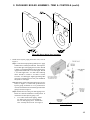
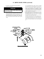
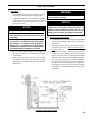
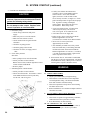
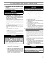
Step 2. If necessary, place your right hand under the
burner air tube to lift upward. Lift the door up unto
the built-in cast ramp/door rest (protruding from the
bottom of the front section casting - see Figure 4A).
E. INSPECT SWING DOOR INSULATION AND ROPE
GASKET.
1. Open burner swing door using procedure previously
outlined in Paragraph D of this section.
Step 3. Use one hand to help hold door in position by
lifting up on rear burner housing or applying pressure
directly to the door while re-installing the securing
hardware with your opposite hand. Always install
right side latching hardware (3/8"-16 x 1-3/4" lg.
tap bolt and flat washer) first, then install left side
hinge hardware (3/8"-16 x 1-3/4" lg. tap bolt and
flat washer) second. Apply additional pressure while
hand tightening the hardware as far as possible, then
release the pressure.
2. Inspect fiberglass rope located on the swing door. The
rope must be evenly distributed around the perimeter of
the door groove and cannot bunch or overhang. There
must not be a gap where the two ends of the rope meet.
Repair or replace if the rope is damaged or if there is a
gap between the ends.
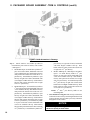
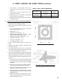
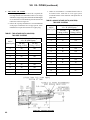
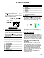
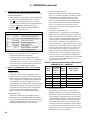
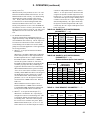
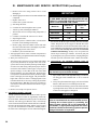
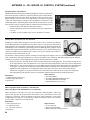
3. Inspect burner swing door insulation for damage and
proper type, refer to Figure 4D.
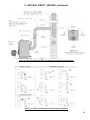
a. By design, cast bars on front section between the
combustion chamber and between the left and right
side 2nd and 3rd pass flueway should make an impression
in door insulation to seal the chambers.
NOTICE
When securing burner swing door make sure door
is drawn-in equally on both sides.
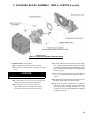
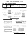
Step 4. Use a hand wrench to tighten door hardware and
always start with the right side cap screw first.
Use an alternating tightening method from right side
tap bolt to left side tap bolt to tighten door equally
until sealed without applying excessive torque. Never
tighten left side flange bolt first or tighten either piece
of hardware 100% without using the alternating
tightening method described above.
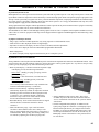
Failure to follow the prescribed procedure could cause
thread damage to casting or a leak in the door seal.
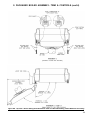
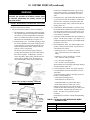
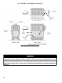
If left side tap bolt is tightened before right side tap
bolt, right side of door can not be drawn-in to provide
an air tight seal, as shown in Figure 4C. Applying
excessive torque will only cause thread damage.
b. By design, door insulation on model MPO-IQ231 will
have two (2) by-pass pockets cast into the insulation
centered on the bar between the combustion chamber
and 3rd pass flueways.
On models MPO-IQ84 thru MPO-IQ189 these pockets
should not be present. If insulation is damaged or not of
proper type regarding pockets, it must be replaced.
4. Do not close and secure door at this time, proceed to Field
Assembly Details, Paragraph F.
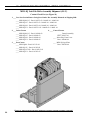
F. Field Assembly of Boiler
Open miscellaneous parts carton and remove contents.
Identify the components using the illustrations (Figures 5
thru 9) throughout the assembly sequence outlined below
as it applies to your installation.
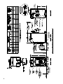
Figure 4C: Top View - Burner Swing Door
Fully Closed but
Not Properly Secured or Sealed
14