Download CAT Articulated Truck 725 Specifications

Transcript
MAINTENANCE INTERVALS
Operation and Maintenance
Manual Excerpt
© 2010 Caterpillar
All Rights Reserved
®
®
SEBU8524
April 2009
Operation and
Maintenance
Manual
725 and 730 OEM Articulated Trucks
WWA1-Up (Machine)
WWB1-Up (Machine)
SAFETY.CAT.COM
104
Maintenance Section
Maintenance Interval Schedule
SEBU8524
i03579720
Maintenance Interval Schedule
SMCS Code: 1000; 7000
Ensure that all safety information, warnings and
instructions are read and understood before any
operation or any maintenance procedures are
performed.
The user is responsible for the performance of
maintenance, including all adjustments, the use of
proper lubricants, fluids, filters, and the replacement
of components due to normal wear and aging. Failure
to adhere to proper maintenance intervals and
procedures may result in diminished performance of
the product and/or accelerated wear of components.
Use mileage, fuel consumption, service hours, or
calendar time, WHICH EVER OCCURS FIRST,
in order to determine the maintenance intervals.
Products that operate in severe operating conditions
may require more frequent maintenance.
Note: Before each consecutive interval is performed,
all maintenance from the previous interval must be
performed.
When Required
Automatic Lubrication Grease Tank - Fill ............ 106
Battery - Recycle ................................................ 108
Battery or Battery Cable - Inspect/Replace ........ 108
Cab Air Filter - Clean/Replace ............................. 113
Circuit Breakers - Reset ....................................... 114
Display and Camera - Clean ............................... 122
Engine Air Filter Primary Element - Clean/
Replace ............................................................. 124
Engine Air Filter Secondary Element - Replace .. 125
Ether Starting Aid Cylinder - Replace ................. 131
Fuses - Replace .................................................. 139
Radiator Core - Clean ......................................... 147
Tire Inflation - Check ........................................... 153
Window Washer Reservoir - Fill .......................... 163
Window Wiper - Inspect/Replace ........................ 163
Windows - Clean ................................................. 164
Every 10 Service Hours or Daily
Backup Alarm - Test ............................................ 108
Brakes, Indicators and Gauges - Test .................. 111
Engine Oil Level - Check .................................... 126
Seat Belt - Inspect .............................................. 150
Wheel Nut Torque - Check .................................. 163
Every 50 Service Hours
Body Pivot Bearings - Lubricate ......................... 109
Cooling System Coolant Level - Check ............... 116
Fuel System Water Separator - Drain ................. 137
Fuel Tank Water and Sediment - Drain ............... 138
Hoist Cylinder Bearings - Lubricate .................... 140
Hydraulic System Oil Level - Check ................... 143
Oscillating Hitch - Lubricate ................................ 146
Steering Cylinder Bearings - Lubricate ............... 151
Suspension and Suspension Cylinder Bearings Lubricate ........................................................... 152
Torque Converter and Transmission Oil Level Check ................................................................ 157
Transfer Gear Oil Level - Check ......................... 161
Initial 500 Service Hours
Engine Valve Lash - Check ................................. 130
Oscillating Hitch - Adjust ..................................... 145
Initial 500 Hours (for New Systems, Refilled
Systems, and Converted Systems)
Cooling System Coolant Sample (Level 2) Obtain ................................................................ 117
Every 500 Service Hours
Belts - Inspect/Adjust/Replace ............................ 108
Brake Pads - Check ............................................. 110
Braking System - Test .......................................... 112
Differential and Final Drive Oil Level - Check ..... 121
Differential and Final Drive Oil Sample - Obtain .. 122
Engine Crankcase Breather - Clean ................... 125
Engine Oil Sample - Obtain ................................ 126
Engine Oil and Filter - Change ........................... 127
Fuel System - Prime ........................................... 134
Fuel System Primary Filter - Clean/Inspect/
Replace ............................................................. 135
Fuel System Secondary Filter - Replace ............ 136
Fuel Tank Cap and Strainer - Clean ................... 137
Hydraulic System Oil Sample - Obtain ............... 144
Hydraulic Tank Strainer - Clean/Inspect/
Replace ............................................................. 145
Secondary Steering - Test .................................. 150
Torque Converter and Transmission Oil Filter Replace ............................................................. 156
Torque Converter and Transmission Oil Sample Obtain ............................................................... 158
Transfer Gear Oil Sample - Obtain ..................... 162
Every 1000 Service Hours
Hydraulic System Oil Filter and Screen Clean/Inspect/Replace ......................................
Oscillating Hitch - Adjust .....................................
Rollover Protective Structure (ROPS) - Inspect ..
Torque Converter and Transmission Oil Change .............................................................
Transfer Gear Oil - Change ................................
Transfer Gear Oil Filter - Replace .......................
142
145
148
153
159
160
Every 2000 Service Hours
Axle Breathers - Clean/Replace ......................... 107
Brake System Air - Purge .................................... 111
Differential and Final Drive Oil - Change ............ 120
SEBU8524
Engine Valve Lash - Check .................................
Engine Valve Rotators - Inspect .........................
Frame and Body - Inspect ..................................
Hydraulic Tank Breather - Clean/Inspect/
Replace .............................................................
Refrigerant Dryer - Replace ................................
105
Maintenance Section
Maintenance Interval Schedule
130
130
131
144
148
Every 2000 Service Hours or 1 Year
Suspension System - Check ............................... 152
Every Year
Brake Accumulator (Service) - Check ................. 109
Every 3000 Service Hours
Cooling System Coolant Extender (ELC) - Add ... 116
Cooling System Coolant Sample (Level 1) Obtain ................................................................ 117
Cooling System Pressure Cap - Clean/Replace .. 118
Every 3 Years After Date of Installation or
Every 5 Years After Date of Manufacture
Seat Belt - Replace ............................................. 150
Every 4000 Service Hours
Hydraulic System Oil - Change ........................... 141
Every 5000 Service Hours
Crankshaft Vibration Damper - Inspect ................ 119
Every 5000 Service Hours or 3 Years
Drive Shaft Universal Joints - Inspect/Replace ... 123
Every 6000 Service Hours
Cooling System Coolant (ELC) - Change ............ 114
Cooling System Water Temperature Regulator Replace .............................................................. 118
106
Maintenance Section
Automatic Lubrication Grease Tank - Fill
SEBU8524
i02695981
Automatic Lubrication Grease
Tank - Fill
(If Equipped)
SMCS Code: 7540-544-TNK
If the yellow LED on the signal lamp is illuminated,
the minimum grease level in the reservoir has been
reached.
• Ensure that the filler hose is primed with grease in
order to prevent air from being introduced in the
grease reservoir.
• Remove the filler hose and fit the dust cap.
• Place the filler hose back in the hose's proper
place in order to ensure that the coupling of the
filler hose remains clean.
Note: Every 500 service hours replace the filter or
every 500 service hours clean the filter for the filler
on the lubrication pump. The filter is behind the
connector on the reservoir.
Note: If the pumping action seems to go heavy,
check the filter behind the coupling for the filler on the
lubrication pump. Gently clean the filter or replace
the filter. If the filter is damaged, the filter must be
replaced.
Note: If too much grease is pumped into the reservoir,
the surplus grease will exit the vent at the side of the
lubrication pump. Any air that is introduced during the
filling procedure will also escape via this route.
Note: Due to the slow capability of a hand held
grease gun, the use of a grease gun is not
recommended in order to fill the reservoir.
Periodic Checks
• Check the grease level in the reservoir. Refill the
reservoir on time.
Illustration 115
g01074471
• Check that the signal lamp is functioning.
Location of the coupling on the lubrication pump
• Remove the dust cap from the coupling for the filler.
• Check that the duty cycle that is indicated on the
• Carefully clean the coupling for the filler and the
• Check the lubrication pump for damage and check
coupling on the filler hose. The coupler for the filler
hose is supplied with each Autolube system.
• Fix the filler hose on the coupling for the filler.
signal lamp is correct for the operating conditions.
the lubrication pump for leakage.
• Check the grease lines for damage and check the
grease lines for leakage.
• Check the conditions of the grease points that
are served by the system. Sufficient fresh grease
should be present.
• Check the operation of the system. Perform a
cycle test. Refer to System Operation, Testing and
Adjusting, RENR6739 for more information.
• Clean the lubrication pump and clean the
surroundings of the lubrication pump.
• Every 500 hours replace the filter or every 500
hours clean the filter.
Illustration 116
g01076025
The maximum level mark on the lubrication pump
• Fill the reservoir up to the maximum level that is
indicated on the reservoir.
Note: When you use high pressure water or high
pressure air to clean the machine, do not spray
directly onto the lubrication pump. Water or dirt may
enter the lubrication pump through the de-arating
openings.
SEBU8524
107
Maintenance Section
Axle Breathers - Clean/Replace
Note: The automatic lubrication system reduces
the time and effort that is taken in order to grease
the machine significantly. However, do not neglect
grease points that are not served by the automatic
lubrication system.
Grease Recommendations
Grease should not contain graphite or PTFE. Use the
correct grease in the automatic lubrication system.
The use of a partially fluid grease that is above the
maximum temperature that is indicated in Table 18
is not permitted. Use of a partially fluid grease that is
above the maximum indicated temperature can lead
to the following.
Illustration 117
g00679632
Front axle breather (1) is mounted on the left side
of the front frame.
• Excessive component wear
• A reduction in the efficiency of the system
Table 18
Minimum
operating
temperature of
the system
Maximum
operating
temperature of
the system
Prescribed
NLGI Grade
−25 °C (−13 °F)
80 °C (176 °F)
2
−25 °C (−13 °F)
0 °C (32 °F)
0/1
−25 °C (−13 °F)
80 °C (176 °F)
SYNTHETIC 2
−25 °C (−13 °F)
0 °C (32 °F)
SYNTHETIC 0/1
Illustration 118
i03579780
Axle Breathers - Clean/Replace
g00679631
Center axle breather (2) is mounted on the right side
of the rear frame.
SMCS Code: 3278-070-BRE; 3278-510-BRE
Park the machine on a level surface. Move the
parking brake control to the ENGAGED position.
Lower the truck body or OEM attachment and shut
off the engine.
Install the Steering Frame Lock. Refer to Operation
and Maintenance Manual, “Steering Frame Lock”.
Illustration 119
g00679629
Rear axle breather (3) is mounted on the right side of
the rear frame.
Note: Before you remove the breathers, block the
front frame of the machine.
1. Remove each axle breather.
108
Maintenance Section
Backup Alarm - Test
SEBU8524
2. Wash each breather in a clean nonflammable
solvent.
Note: When you replace the batteries, always use
the same type of battery.
3. Shake each breather until the breather is dry.
Use the following procedure in order to isolate the
batteries if any repairs are necessary.
4. Install each breather.
If any of the axle breathers are damaged, replace the
damaged breather.
Remove the Steering Frame Lock once all the axle
breathers are installed. Refer to Operation and
Maintenance Manual, “Steering Frame Lock”.
i02305428
Backup Alarm - Test
1. Turn the engine start switch to the OFF position.
Turn all switches to the OFF position.
2. Turn the battery disconnect switch to the OFF
position. Remove the key.
3. At the battery disconnect switch, disconnect the
negative battery cable that is connected to the
frame.
Note: Do not allow the disconnected battery cable to
contact the disconnect switch.
SMCS Code: 7406-081
The backup alarm is on the rear of the machine.
4. Disconnect the negative battery cable from the
terminals of the batteries.
Turn the engine start switch to the ON position in
order to perform the test.
5. Perform the necessary repairs. Replace the
cables or the batteries, as needed.
Apply the service brakes. Move the transmission
control lever to the REVERSE position.
6. Connect the negative battery cable to the
terminals of the battery.
The backup alarm should start to sound immediately.
The backup alarm will continue to sound until the
transmission control lever is moved to the NEUTRAL
position or to the FORWARD position.
7. Connect the negative battery cable at the battery
disconnect switch.
8. Install the key for the battery disconnect switch.
Turn the key to the ON position.
i02039199
Battery - Recycle
i02210445
Belts - Inspect/Adjust/Replace
SMCS Code: 1401-561
SMCS Code: 1357-025; 1357-040; 1357-510
Always recycle a battery. Never discard a battery.
Return used batteries to one of the following
locations:
The engine is equipped with a belt that drives the
alternator and the air conditioner.
Note: The engine is equipped with a belt tensioner
that automatically adjusts the belt to the correct
tension.
• A battery supplier
• An authorized battery collection facility
1. Park the machine on a level surface. Engage the
parking brake. Shut off the engine.
• A recycling facility
i01951790
Battery or Battery Cable Inspect/Replace
SMCS Code: 1401-510; 1402-510
Inspect the condition of the cables to the batteries
and inspect the condition of the batteries.
2. Raise the hood. Refer to Operation and
Maintenance Manual, “Hood Control”.
3. Remove the pulley guard.
4. Inspect drive belt (1). Check the belt for wear,
fraying or cracking. If the belt is damaged, replace
the belt.
SEBU8524
Illustration 120
109
Maintenance Section
Body Pivot Bearings - Lubricate
g01127107
5. If belt (1) requires replacement, insert a square
drive into the hole in tensioner (3) and turn
counterclockwise in order to release the tension
from the belt.
6. Remove the belt from the engine.
7. In order to Install a new belt, insert a square
drive into the hole in tensioner (3) and turn
counterclockwise.
8. Install belt (1) in the following order: tensioner (3),
idler (2), drive pulleys (5), and idler (4).
9. Install the pulley guard.
Illustration 121
g01126063
There is a total of two grease fittings. One grease
fitting on the end of each pivot pin. The fittings are
located at the rear of the machine.
Lubricate the pivot bearings through the grease
fittings. One or two shots will be required at each
fitting if lubrication is carried out at the recommended
interval.
i02253515
Brake Accumulator (Service) Check
SMCS Code: 4263-535
10. Lower the hood. Refer to Operation and
Maintenance Manual, “Hood Control”.
i03579844
Body Pivot Bearings Lubricate
(OEM Attachment if Equipped)
SMCS Code: 7258-086-BD; 7424-086
Note: The OEM Articulated Truck may be equipped
with either a truck body or a OEM attachment. The
operation of the OEM attachment is very similar to
the operation of the truck body.
Park the machine on a level surface. Ensure that the
parking brake is fully engaged. Lower the truck body
or OEM attachment and stop the engine.
Remove the caps and wipe the grease fittings before
lubricant is applied. Install the caps after lubricant
has been applied.
Personal injury or death can result from improper
accumulator charging.
Dry Nitrogen is the only gas approved for use in
the accumulator. Charging the accumulator with
oxygen will cause an explosion. This danger will
not happen if nitrogen cylinders with standard
CGA (Compressed Gas Association, Inc.) Number
580 connections are used.
When ordering nitrogen gas, be sure that the cylinders are equipped with CGA Number 580 connections. Do not use color codes or other methods of
identification to tell the difference between nitrogen and oxygen cylinders
Never use an adapter to connect your nitrogen
charging group to a valve outlet used on both nitrogen, oxygen, or other gas cylinders. BE SURE
YOU USE DRY NITROGEN (99.8% purity).
Refer to Systems Operation, Testing and Adjusting,
“Brake Accumulator (Service) - Test and Charge” for
more information.
110
Maintenance Section
Brake Pads - Check
SEBU8524
i02310318
Brake Pads - Check
SMCS Code: 4251-535; 4267-535; 4273-535
A tool can be manufactured in order to facilitate
measurements by using the following information.
g01146003
Illustration 122
Fabricate a tool from suitable black steel stock or
suitable mild steel bar. Refer to Illustration 122 and
Table 19.
Table 19
Dimension
(1)
A
235 ± 5 mm
(9.25 ± 0.20 inch)
B
82 ± 0.25 mm
(3.23 ± 0.01 inch)(1)
C
63 ± 0.25 mm
(2.48 ± 0.01 inch)(1)
D
5.0 ± 0.25 mm
(0.20 ± 0.01 inch) diameter
E
10.0 ± 0.25 mm
(0.40 ± 0.01 inch) diameter
F
0.5 mm (0.02 inch)
max radius
This dimension is critical to the purpose of the tool.
Illustration 123
Typical example
g01145658
SEBU8524
111
Maintenance Section
Brake System Air - Purge
In order to measure the thickness of the brake linings,
locate the two holes on the caliper for measuring the
brake linings. Refer to Illustration 123. Remove any
plugs from the holes and clean the holes of any dirt.
When the pads are worn, the step on the tool
will touch the caliper. When this happens, inspect
the brake linings. This indicator will show that
approximately 90% of the life of the brake lining has
been reached. Individual measurements must be
recorded for rotors which have been machined or
excessively worn.
Note: The gauge needs to be used in both holes
because lining pads might not wear evenly.
i02239865
Brake System Air - Purge
SMCS Code: 4250-ABL; 4251
Illustration 124
g01150338
Illustration of the correct method of taking a measurement with
the tool
The step on the tool is indicated in the Illustration with an arrow.
Routine purging of the service brake lines ensures
that the system is free of air. Purge the brake groups
for the center axle and purge the brake groups for
the front axle.
Refer to the appropriate Systems Operation, Testing
and Adjusting, “Service Brake Air - Purge” for more
information.
i01514959
Brakes, Indicators and Gauges
- Test
SMCS Code: 4251-081; 4267-081; 7000; 7450-081;
7490-081
Before you operate the machine, perform the
following checks and make any necessary repairs.
Illustration 125
g01150339
Illustration of the correct method of taking a measurement with
the tool
• Look for broken lenses on the gauges, broken
indicator lights, broken switches, and other broken
components in the cab.
The step on the tool is indicated in the Illustration with an arrow.
Insert the tool into one of the holes on the caliper
until the end of the tool touches the brake lining or
the step on the tool touches the caliper. Refer to
Illustration 124 and Illustration 125.
The tool has two ends of different lengths. Due to
the thickness of the casting, there is approximately
a 20 mm (0.80 inch) difference between the depth
of the two holes in the casting. Ensure that the
correct end of the tool is used in the correct hole for
measuring the thickness of the brake linings.
• Start the engine.
• Look for inoperative gauges.
• Turn on all machine lights. Check for proper
operation.
• Sound the forward horn.
• Test the service brakes. Refer to Operation and
Maintenance Manual, “Braking System - Test”.
• Test the parking brake. Refer to Operation and
Maintenance Manual, “Braking System - Test”.
• Stop the engine.
112
Maintenance Section
Braking System - Test
SEBU8524
i03579861
Braking System - Test
SMCS Code: 3077-081; 4251-081; 4267-081
NOTICE
If the machine moved while testing the service brakes,
contact your Caterpillar dealer.
Have the dealer inspect and, if necessary, repair the
service brakes before returning the machine to operation.
Personal injury can result if the machine moves
while testing.
If the machine begins to move during test, reduce
the engine speed immediately and engage the
parking brake.
The service brake holding ability test determines
whether the service brake is functional. This test is
not intended to measure the maximum brake holding
ability.
The holding ability of the service brakes at a specific
engine rpm will be different for each machine.
The results of the test should be recorded. The
results should be compared to previous test results
and subsequent test results. Use the comparison as
an indication of system deterioration for a particular
machine.
1. Before you perform the test, ensure that you can
test the brakes on a surface which is level, dry,
and clear of obstacles. Fasten your seat belt.
Ensure that the transmission control is in the N
position and that the parking brake control is in
the ENGAGED position.
Start the engine and wait until the brake system is
fully charged.
2. Engage the service brakes. Move the transmission
control to the 1 position. Move the parking brake
control to the DISENGAGED position.
3. Gradually increase the engine speed until the
machine moves forward. Record the engine speed
when the machine moves.
Reduce the engine speed immediately and move
the parking brake control to the ENGAGED
position. Move the transmission control to the N
position. Shut off the engine.
4. If the machine moves at an engine speed below
1200 rpm, the service brakes require service.
Parking Brake Check
The test for the parking brake must be carried out with
the rated load in the truck body or OEM attachment.
Test the service brakes and the secondary steering
system on level ground before you carry out this
procedure.
1. Drive the machine onto an incline of 15%. The
machine must be pointing down the incline.
2. Engage the service brakes in order to stop
the machine on the incline. The area around
the machine must be clear of personnel and
obstacles.
3. Move the parking brake control to the ENGAGED
position. Move the transmission control to the N
position.
4. Shut off the engine.
5. Gradually disengage the service brakes.
6. If the machine moves forward, engage the service
brakes immediately. Start the engine. Disengage
the parking brake and drive the machine onto
level ground. Shut off the engine.
7. Check the thickness of the brake pad linings
and check the thickness of the brake disc. Refer
to Specifications, RENR6724, “Parking Brake”.
Replace parts if the specification is not met.
If the machine moved during the test, the parking
brake requires service.
NOTICE
If the machine moved while testing the parking brake,
inspect the parking brake components for wear or
damage. Repair or replace the worn or damaged parking brake components as required before returning the
machine to service.
SEBU8524
113
Maintenance Section
Cab Air Filter - Clean/Replace
i03579870
Cab Air Filter - Clean/Replace
3. Remove cover (2) and remove the air filter.
4. Clean the inside of both air filter housings.
SMCS Code: 7342-070; 7342-510
NOTICE
An air recirculation filter element plugged with dust will
result in decreased performance and service life to the
air conditioner or cab heater.
To prevent decreased performance, clean the filter element, as required.
Both cab air filters must be serviced at regular
intervals. Operating conditions will influence the
service interval for the cab air filters. Inspect the
filters more often in very dusty conditions. Both cab
air filters are located in the right side wall of the cab.
Replace both air filters if the air filter elements have
been in service for one year.
1. Park the machine on a level surface. move the
parking brake control to the ENGAGED position.
Lower the truck body or OEM attachment and shut
off the engine.
Illustration 128
g01125369
5. Inspect each air filter. If the pleats or the seals are
damaged, replace the air filter.
6. If the air filter is not damaged, clean the air filter
with pressurized air. the maximum air pressure for
cleaning is 205 kPa (30 psi).
Direct pressurized air along the pleats from no
closer than 160 mm (6 inch) from the air filter.
If the air filter is damaged, replace the air filter.
7. Install the air filters. Use the arrows on the air
filters as a guide for correct installation.
8. Install cover (2) and cover (1).
Illustration 126
g01125350
2. Remove cover (1) and remove the air filter.
Illustration 127
g01125366
114
Maintenance Section
Circuit Breakers - Reset
SEBU8524
i02379720
Hood Control Switch (3)
Circuit Breakers - Reset
SMCS Code: 1420-529
Circuit Breakers for the Alternator
and for the Battery
i03579879
Cooling System Coolant (ELC)
- Change
SMCS Code: 1350-044-NL
Personal injury can result from hot coolant, steam
and alkali.
At operating temperature, engine coolant is hot
and under pressure. The radiator and all lines
to heaters or the engine contain hot coolant or
steam. Any contact can cause severe burns.
Illustration 129
g01188303
The circuit breakers for the alternator and the battery
are located on the front left of the machine under a
panel on the battery compartment. Circuit breaker
(1) for the battery protects the battery from a dead
short. Circuit breaker (2) for the alternator protects
the alternator from a power surge. Reset the circuit
breaker if the circuit breaker trips. Press in the button
in order to reset the circuit. If the button does not
remain pressed or if the circuit breaker trips soon
after being reset, check the appropriate electrical
circuit. Repair the electrical circuit, if necessary.
Battery (1)
Alternator (2)
Circuit Breaker for the Hood
Control Switch
The circuit breaker for the hood control switch
is located with the battery and alternator circuit
breakers. Reset the circuit breaker if the circuit
breaker trips. Press in the button in order to reset
the circuit. If the button does not remain pressed or
the circuit breaker trips soon after being reset, check
the electrical circuit. Repair the electrical circuit, if
necessary.
Remove cooling system pressure cap slowly to
relieve pressure only when engine is stopped and
cooling system pressure cap is cool enough to
touch with your bare hand.
Do not attempt to tighten hose connections when
the coolant is hot, the hose can come off causing
burns.
Cooling System Coolant Additive contains alkali.
Avoid contact with skin and eyes.
NOTICE
Do not change the coolant until you read and understand the cooling system information in Special Publication, SEBU6250, “Caterpillar Machine Fluids Recommendations”.
Failure to do so could result in damage to the cooling
system components.
NOTICE
Mixing Extended Life Coolant (ELC) with other products reduces the effectiveness of the coolant and
shortens coolant life. Use only Caterpillar products
or commercial products that have passed the Caterpillar EC-1 specification for premixed or concentrate
coolants. Use only Caterpillar Extender with Caterpillar ELC. Failure to follow these recommendations
could result in the damage to cooling systems components.
SEBU8524
115
Maintenance Section
Cooling System Coolant (ELC) - Change
NOTICE
Care must be taken to ensure that fluids are contained
during performance of inspection, maintenance, testing, adjusting and repair of the product. Be prepared to
collect the fluid with suitable containers before opening any compartment or disassembling any component containing fluids.
2. Remove the cover from the front of the crankcase
guard in order to access the drain valve. Three
bolts fasten the cover to the crankcase guard.
Refer to Special Publication, NENG2500, “Caterpillar
Dealer Service Tool Catalog” for tools and supplies
suitable to collect and contain fluids on Caterpillar
products.
Dispose of all fluids according to local regulations and
mandates.
If the coolant is dirty or if you observe any foaming
in the cooling system, change the coolant before the
recommended interval.
Park the machine on a level surface. Ensure that
the parking brake is fully engaged. Lower the truck
body or OEM attachment and shut off the engine.
Do not perform this procedure until the coolant has
fully cooled.
Illustration 132
3. Open the drain valve. Allow the coolant to drain
into a suitable container.
4. Close the drain valve.
Illustration 133
Illustration 130
g01126897
1. Slowly remove the cap in order to gradually relieve
any system pressure.
g01127289
g01126946
5. The tube assembly that is located near the front
of the engine must be vented in order to ensure
proper filling of the cooling system. Failure to vent
this tube assembly may cause the water pump to
cavitate. The tube assembly may be vented in one
of two ways. The tube assembly may be vented
by removing the 154-9024 Sampling Valve.
The tube assembly may also be vented by
purchasing a 177-9343 Fluid Sampling Cap and
Probe Gp from your Caterpillar dealer. Remove
the dust cap from the valve . The probe may be
inserted into the 154-9024 Sampling Valve in
order to vent the tube assembly. The probe must
be held in place.
Add Extended Life Coolant to the coolant tank
until the tube assembly is full.
Illustration 131
g01127288
Install the 154-9024 Sampling Valve or remove
the probe. Secure the dust cap to the valve.
116
Maintenance Section
Cooling System Coolant Extender (ELC) - Add
Add Extended Life Coolant until the level in the
coolant tank is halfway between the top and the
bottom of the sight glass (2).
6. Start the engine. Run the engine until the water
temperature regulator opens and the coolant level
stabilizes.
SEBU8524
i03579888
Cooling System Coolant Level
- Check
SMCS Code: 1350-535-FLV
Note: Do not install the cap.
7. Add Extended Life Coolant until the level reaches
halfway up sight glass (2). Refer to Operation and
Maintenance Manual, “Capacities (Refill)” for the
required amount of Extended Life Coolant.
Pressurized system: Hot coolant can cause serious burn. To open cap, stop engine, wait until radiator is cool. Then loosen cap slowly to relieve
the pressure.
8. Inspect the cap. If the cap is damaged, replace
the cap.
Park the machine on a level surface. Ensure that the
parking brake is fully engaged. Lower the truck body
or OEM attachment and shut off the engine.
9. Install the cap.
10. Shut off the engine.
i01865470
Cooling System Coolant
Extender (ELC) - Add
SMCS Code: 1352-544-NL
When a Caterpillar Extended Life Coolant (ELC)
is used, an extender must be added to the cooling
system. See the Operation and Maintenance
Manual, “Maintenance Interval Schedule” for the
proper service interval. The amount of extender is
determined by the cooling system capacity.
Table 20
Cooling System Capacity
Recommended Amount
of Caterpillar Extender
22 to 30 L (6 to 8 US gal)
0.57 L (20 oz)
30 to 38 L (8 to 10 US gal)
0.71 L (24 oz)
38 to 49 L (10 to 13 US gal)
0.95 L (32 oz)
49 to 64 L (13 to 17 US gal)
1.18 L (40 oz)
64 to 83 L (17 to 22 US gal)
1.60 L (54 oz)
83 to 114 L (22 to 30 US gal)
2.15 L (72 oz)
114 to 163 L (30 to 43 US gal)
3.00 L (100 oz)
163 to 242 L (43 to 64 US gal)
4.40 L (148 oz)
For additional information about adding an extender,
see Special Publication, SEBU6250 or consult your
Caterpillar Dealer.
Illustration 134
g01125467
The tank for the cooling system is located at the rear
of the cab.
The tank for the cooling system features a sight glass
(1).
Check the cooling system level in the coolant tank.
The coolant level should be maintained halfway
between the top and the bottom of the transparent
tube of the sight glass on the coolant tank.
Add coolant, if necessary. Refer to Operation and
Maintenance Manual, “Cooling System Coolant Change” for information on adding coolant.
SEBU8524
117
Maintenance Section
Cooling System Coolant Sample (Level 1) - Obtain
i02210457
• Obtain coolant samples directly from the coolant
sample port. You should not obtain the samples
from any other location.
Cooling System Coolant
Sample (Level 1) - Obtain
• Keep the lids on empty sampling bottles until you
are ready to collect the sample.
SMCS Code: 1395-554
NOTICE
Care must be taken to ensure that fluids are contained
during performance of inspection, maintenance, testing, adjusting and repair of the product. Be prepared to
collect the fluid with suitable containers before opening any compartment or disassembling any component containing fluids.
Refer to Special Publication, NENG2500, “Caterpillar
Tools and Shop Products Guide” for tools and supplies
suitable to collect and contain fluids on Caterpillar
products.
Dispose of all fluids according to local regulations and
mandates.
• Place the sample in the mailing tube immediately
after obtaining the sample in order to avoid
contamination.
• Never collect samples from expansion bottles.
• Never collect samples from the drain for a system.
Submit the sample for Level 1 analysis.
For additional information about coolant analysis, see
Special Publication, SEBU6250, “Caterpillar Machine
Fluids Recommendations” or consult your Caterpillar
dealer.
i02210451
Note: Level 1 results may indicate a need for
Level 2 Analysis.
Cooling System Coolant
Sample (Level 2) - Obtain
SMCS Code: 1395-554
NOTICE
Care must be taken to ensure that fluids are contained
during performance of inspection, maintenance, testing, adjusting and repair of the product. Be prepared to
collect the fluid with suitable containers before opening any compartment or disassembling any component containing fluids.
Illustration 135
g01126946
Obtain the sample of the coolant as close as possible
to the recommended sampling interval. In order
to receive the full effect of S·O·S analysis, you
must establish a consistent trend of data. In order
to establish a pertinent history of data, perform
consistent samplings that are evenly spaced.
Supplies for collecting samples can be obtained from
your Caterpillar dealer.
Refer to Special Publication, NENG2500, “Caterpillar
Tools and Shop Products Guide” for tools and supplies
suitable to collect and contain fluids on Caterpillar
products.
Dispose of all fluids according to local regulations and
mandates.
Use the following guidelines for proper sampling of
the coolant:
• Complete the information on the label for the
sampling bottle before you begin to take the
samples.
• Keep the unused sampling bottles stored in plastic
bags.
Illustration 136
g01126946
118
Maintenance Section
Cooling System Pressure Cap - Clean/Replace
Obtain the sample of the coolant as close as possible
to the recommended sampling interval. Supplies
for collecting samples can be obtained from your
Caterpillar dealer.
Refer to Operation and Maintenance Manual,
“Cooling System Coolant Sample (Level 1) - Obtain”
for the guidelines for proper sampling of the coolant.
Submit the sample for Level 2 analysis.
SEBU8524
4. Install the cap.
i02235376
Cooling System Water
Temperature Regulator Replace
SMCS Code: 1355-510
Reference: For additional information about coolant
analysis, refer to Special Publication, SEBU6250,
“Caterpillar Machine Fluids Recommendations” or
consult your Caterpillar dealer.
i03579898
Cooling System Pressure Cap
- Clean/Replace
Personal injury can result from hot coolant, steam
and alkali.
At operating temperature, engine coolant is hot
and under pressure. The radiator and all lines
to heaters or the engine contain hot coolant or
steam. Any contact can cause severe burns.
Remove filler cap slowly to relieve pressure only
when engine is stopped and radiator cap is cool
enough to touch with your bare hand.
SMCS Code: 1382-070; 1382-510
Pressurized system: Hot coolant can cause serious burn. To open cap, stop engine, wait until radiator is cool. Then loosen cap slowly to relieve
the pressure.
Do not attempt to tighten hose connections when
the coolant is hot, the hose can come off causing
burns.
Cooling System Conditioner contains alkali. Avoid
contact with skin and eyes.
1. Park the machine on a level surface. Ensure that
the parking brake is fully engaged. Lower the truck
body or OEM attachment and shut off the engine.
Do not perform this procedure until the coolant
has fully cooled.
Illustration 138
Illustration 137
g01126897
2. Remove the cap slowly in order to gradually
relieve any system pressure.
3. Inspect the cap for damage, for foreign material,
and for deposits. If the cap is damaged, replace
the cap. If the cap is not damaged, clean the cap
with a clean cloth.
g01127304
There are two water temperature regulators. The
water temperature regulator housing is located at the
front of the engine near the alternator.
It is necessary to remove the water temperature
regulator housing in order to replace the water
temperature regulators. Refer to Disassembly
and Assembly, SENR9537, “Water Temperature
Regulator - Remove and Install” for a typical
procedure.
SEBU8524
119
Maintenance Section
Crankshaft Vibration Damper - Inspect
It is necessary to remove the alternator, the
bracket for the alternator, and the drive belt. These
components must be removed in order to allow the
removal of the water temperature regulator housing.
Refer to Disassembly and Assembly, SENR9537 for
the removal procedures for these components.
Replace the water temperature regulators while the
cooling system is completely drained or while the
cooling system coolant is drained to a level that is
below the water temperature regulator housing.
Refer to Operation and Maintenance Manual,
“Cooling Syatem Coolant - Change” for information
on draining the cooling system.
NOTICE
Failure to replace the engine's water temperature regulator on a regularly scheduled basis could cause severe engine damage.
NOTICE
The water temperature regulators may be reused if the
water temperature regulators are within test specifications, are not damaged, and do not have excessive
buildup of deposits.
NOTICE
Since Caterpillar engines incorporate a shunt design
cooling system, it is mandatory to always operate the
engine with a water temperature regulator.
Illustration 139
g01127166
The crankshaft vibration damper can be viewed from
the right side of the engine compartment.
Damage to the vibration damper or failure of the
vibration damper will increase torsional vibrations.
These vibrations will result in damage to the
crankshaft and other engine components. A
deteriorating vibration damper will cause excessive
gear train noise at variable points in the speed range.
Caterpillar recommends replacing the vibration
damper for any of the following reasons.
• The engine has had a failure because of a broken
crankshaft.
• The S·O·S analysis detected a worn crankshaft
front bearing.
Depending on load, failure to operate with a water
temperature regulator could result in either an overheating or an overcooling condition.
• The S·O·S analysis detected a large amount of
NOTICE
If the water temperature regulator is installed incorrectly, it will cause the engine to overheat.
Continue to use the crankshaft vibration damper
if none of the above conditions are found or if the
damper is not damaged.
i03579907
Crankshaft Vibration Damper
- Inspect
SMCS Code: 1205-040
Park the machine on a level surface. Ensure that
the parking brake is fully engaged. Lower the truck
body or OEM attachment and shut off the engine.
Raise the hood. Refer to Operation and Maintenance
Manual, “Hood Control”.
gear train wear that is not caused by a lack of oil.
Refer to the Disassembly and Assembly, SENR9537,
“Crankshaft Vibration Damper and Pulley - Remove
and Install” in order to replace the vibration damper.
120
Maintenance Section
Differential and Final Drive Oil - Change
SEBU8524
i02232197
Differential and Final Drive Oil
- Change
6. Repeat Step 2 through Step 4 for the rear right
final drive.
SMCS Code: 3258-044; 4050-044
NOTICE
Care must be taken to ensure that fluids are contained
during performance of inspection, maintenance, testing, adjusting and repair of the product. Be prepared to
collect the fluid with suitable containers before opening any compartment or disassembling any component containing fluids.
Refer to Special Publication, NENG2500, “Caterpillar
Tools and Shop Products Guide” for tools and supplies
suitable to collect and contain fluids on Caterpillar
products.
Dispose of all fluids according to local regulations and
mandates.
1. Operate the machine until the differential oil is
warm. Park the machine on a level surface.
Illustration 141
g01125939
7. Remove drain plug (2) and level plug (3) from the
rear axle. Remove the drain plug slowly in order to
gradually release any system pressure. Allow the
oil to drain into a suitable container.
8. Clean the drain plug and inspect the O-ring seal
for damage. Lubricate the O-ring seal with gear oil
and install the drain plug.
Note: The drain plug is magnetic. Check the plug
for ferrous particles that may indicate wear of the
differential and final drive components.
9. Start the engine and disengage the parking brake.
Illustration 140
g01125937
2. Slowly move the machine until plug (1) is at the
lowest point on the rear left final drive. Engage the
parking brake and shut off the engine.
3. Wipe the area around plug (1) on the final drive.
Remove plug (1). Remove the plug slowly in order
to gradually release any system pressure. Allow
the oil to drain into a suitable container.
4. Clean plug (1) and inspect the O-ring seal for
damage. Lubricate the O-ring seal with gear oil
and install the plug.
Note: The plug is magnetic. Check the plug for
ferrous particles that may indicate wear of the
differential and final drive components.
5. Start the engine and disengage the parking brake.
Illustration 142
g01125942
10. Slowly move the machine until “Oil Level” mark
(4) on the rear right final drive is horizontal.
Engage the parking brake and shut off the engine.
11. Remove plug (1) from the front right final drive
and add oil to the final drive. Refer to Operation
and Maintenance Manual, “Capacities (Refill)” and
Operation and Maintenance Manual, “Lubricant
Viscosities”.
SEBU8524
121
Maintenance Section
Differential and Final Drive Oil Level - Check
Fill the final drive to the bottom of the plug hole.
Allow the oil to flow along the axle housing and
settle at a common level.
12. Install plug (1).
13. Repeat steps 9 through 12 for the rear left final
drive.
14. Remove level plug (3) from the rear axle. Add oil
to the differential until the differential is full. Refer to
Operation and Maintenance Manual, “Capacities
(Refill)” and Operation and Maintenance Manual,
“Lubricant Viscosities”.
Illustration 143
15. Install the plug.
g01293542
Typical example
16. Repeat the procedure for the center differential
and final drives.
Repeat the procedure for the front differential and
final drives.
Some models may have the filler plug toward the right side.
2. Remove differential filler plug (1) and clean the
area around the opening.
17. Start the engine.
3. Check the oil level. Maintain the oil level to the
bottom of the filler plug opening.
18. Operate the machine for a few minutes in order
to circulate the oil.
4. If necessary, add oil. Install the filler plug.
19. Shut off the engine.
20. Check the oil level of the differential and final
drives. Refer to Operation and Maintenance
Manual, “Differential and Final Drive Oil Level Check”.
i02582439
Differential and Final Drive Oil
Level - Check
SMCS Code: 3258-535-FLV; 4050-535-FLV
1. Park the machine on a level surface and stop the
engine. Perform the following steps on each of
the three axles:
Illustration 144
g01293543
Typical Example
Note: The differential and final drives share a
common oil compartment. When the machine is
parked on a level surface and when the final drive oil
level mark (3) is horizontal, the final drive filler plug
(2) will be at the same level as the differential filler
plug (1). Allow the oil to fill all of the compartments
before rechecking the oil level.
122
Maintenance Section
Differential and Final Drive Oil Sample - Obtain
SEBU8524
i02210940
Differential and Final Drive Oil
Sample - Obtain
SMCS Code: 3258-008; 4050-008; 7542-008
Note: Use a sampling gun for obtaining the oil
samples.
Illustration 146
g01125892
8. Wipe the area around plug (3) on the rear axle
housing. Remove the plug and the O-ring seal.
Remove the plug slowly in order to gradually
relieve any system pressure.
9. Obtain an oil sample through the plug hole in the
front axle housing.
Illustration 145
g01116160
1. Park the machine on level ground. Slowly move
the machine until “Oil Level” mark (1) on the front
right final drive is horizontal. Engage the parking
brake and shut off the engine.
2. Wipe the area around plug (2) on the final drive.
Remove the plug and the O-ring seal. Remove
the plug slowly in order to gradually relieve any
system pressure.
3. Obtain an oil sample through the plug hole in the
final drive.
4. Clean the plug and check the plug for ferrous
particles that may indicate wear of the final drive
and differential components.
10. Clean the plug and check the plug for ferrous
particles that may indicate wear of the differential
and final drive components.
11. Lubricate the O-ring seal with gear oil. Install the
plug and the O-ring seal.
12. Repeat steps 8 through 11 for the center axle and
the front axle.
13. Use S·O·S Oil Analysis in order to monitor
the condition of the differential and final drive
components.
i02449906
5. Lubricate the O-ring seal with gear oil. Install the
plug and the O-ring seal.
Display and Camera - Clean
(If Equipped with Work Area
Vision System)
6. Start the engine.
SMCS Code: 7347-070; 7348-070
7. Repeat Steps 1 through 6 in order to obtain oil
samples from the final drives on the remaining
five wheels.
In order to maintain sufficient vision, keep the Work
Area Vision System (WAVS) camera lens and the
display clean.
SEBU8524
123
Maintenance Section
Drive Shaft Universal Joints - Inspect/Replace
Display
i03579936
Drive Shaft Universal Joints Inspect/Replace
SMCS Code: 3251-040; 3251-510
Park the machine on a level surface and engage
the parking brake. Lower the truck body or OEM
attachment and stop the engine.
Inspect
Illustration 147
g01223034
WAVS display
Use a soft, damp cloth in order to clean the display.
The display has a soft plastic surface that can be
easily damaged by an abrasive material. The display
is not sealed. Do not immerse the display with
liquid.
Camera
1. Place a dial indicator on the drive shaft so that the
vertical end play in the spider can be measured.
If the drive shaft moves more than 0.15 mm
(0.006 inch) of movement relative to the yoke, the
spider needs to be replaced.
2. Place the dial indicator so that the horizontal
end play in the spider can be measured. If the
spider has more than 0.15 mm (0.006 inch) of
movement relative to the yoke, the spider needs
to be replaced.
Replace
Do not reuse drive shaft bolts. Always use new drive
shaft bolts when you reassemble the drive shaft.
Illustration 148
g01223051
The WAVS camera is located on the rear of the machine near
the taillights.
Use a damp cloth or water spray in order to clean
the camera lens. The camera is a sealed unit. The
camera is not affected by high pressure spray.
The camera is equipped with an internal heater to
help counteract the effects of condensation, snow,
or ice.
Note: For more information on WAVS, refer to
Operation and Maintenance Manual, SEBU8157,
“Work Area Vision System”.
Illustration 149
g01402610
Torque sequence
1. Use four used bolts as alignment bolts. Install the
used bolts. Tighten the bolts in the pattern that is
shown in Illustration 149. Make sure that the yoke
is fully seated against the spider. Torque the used
bolts to the designed specification.
124
Maintenance Section
Engine Air Filter Primary Element - Clean/Replace
SEBU8524
2. Remove the used bolts one at a time. Follow the
pattern that is shown in Illustration 149. Install the
new bolt. Torque the new bolt before removing the
next alignment bolt in the pattern.
3. Check the torque of the new bolts by using the
pattern that is shown in Illustration 149.
i03580034
Engine Air Filter Primary
Element - Clean/Replace
SMCS Code: 1054-070-PY; 1054-510-PY
Illustration 151
NOTICE
Service the air cleaner only with the engine stopped.
Engine damage could result.
g00681242
• The indicator for the air filter is illuminated. Refer to
3. Primary air filter element (3) fits tightly onto air
cleaner housing (4). Carefully release the seal by
rocking or twisting the primary air filter element
and remove the primary air filter element from the
air cleaner housing. Avoid touching the primary
air filter element against the sides of the air
cleaner housing as this may dislodge dust from
the primary air filter element.
• The primary air filter element has been in service
4. Inspect the primary air filter element. If the pleats
or the seals are damaged, replace the primary air
filter element.
Service the primary air filter element under the
following conditions.
Operation and Maintenance Manual, “Monitoring
System”.
for 1000 service hours.
Park the machine on a level surface. Ensure that the
parking brake is fully engaged. Lower the truck body
or OEM attachment and shut off the engine.
Personal injury can result from air pressure.
1. Raise the hood.
Personal injury can result without following proper procedure. When using pressure air, wear a protective face shield and protective clothing.
Refer to the Operation and Maintenance Manual,
“Hood Control”.
Maximum air pressure at the nozzle must be less
than 205 kPa (30 psi) for cleaning purposes.
5. If the primary air filter element is not damaged,
clean the inside pleats and the outside pleats. The
following method may be used in order to clean
the primary air filter element:
• Pressurized air (Maximum pressure 205 kPa
(30 psi))
Direct pressurized air along the pleats from no
closer than 160 mm (6 inch) from the primary air
filter element.
Illustration 150
g00681241
2. Release three latches (1) and remove air cleaner
cover (2).
A primary air filter element may be cleaned for a
maximum of six times. Replace a primary air filter
element after one service year.
Note: Do not clean the primary air filter element
by bumping or by tapping as this may damage the
primary air filter element.
SEBU8524
125
Maintenance Section
Engine Air Filter Secondary Element - Replace
6. Inspect the primary air filter element before
installation. If the pleats, the gaskets, or the
seals are damaged, replace the primary air filter
element.
Refer to the Operation and Maintenance
Manual, “Engine Air Filter Primary
Element-Clean/Replace”.
7. Clean the inside of the air cleaner housing.
8. Install a clean, dry primary air filter element.
ensure that the seal is made between the primary
air filter element and the air cleaner housing.
9. Clean the air cleaner cover. Install the air cleaner
cover and engage the latches.
10. Lower the hood.
Refer to the Operation and Maintenance Manual,
“Hood Control”.
Illustration 152
11. Start the engine. If the indicator for the air filter
is illuminated replace the secondary air filter
element.
Refer to the Operation and Maintenance Manual,
“Engine Air Filter Secondary Element - Replace”.
i03580064
Engine Air Filter Secondary
Element - Replace
SMCS Code: 1054-510-SE
NOTICE
Always replace the secondary element. Do not attempt to reuse it by cleaning. Engine damage could
result.
NOTICE
Service the air cleaner only with the engine stopped.
Engine damage could result.
g00681252
2. Carefully release the seal by rocking or twisting
secondary air filter element (1). Remove the
secondary air filter element from air cleaner
housing (2).
3. Cover the air inlet opening. Clean the inside of
the air cleaner housing.
4. Uncover the air inlet opening. Install a new
secondary air filter element. Ensure that the seal
is made between the secondary air filter element
and the air cleaner housing.
5. Install the primary air filter element.
Refer to the Operation and Maintenance
Manual, “Engine Air Filter Primary
Element-Clean/Replace”.
6. Install the air cleaner cover and engage the three
latches.
7. Lower the hood. Refer to Operation and
Maintenance Manual, “Hood Control”.
Replace the secondary air filter element under these
conditions.
i03580099
• The primary air filter element is serviced for the
Engine Crankcase Breather Clean
• The indicator for the air filter is illuminated after the
SMCS Code: 1317-070
third time.
primary air filter element has been serviced. Refer
to Operation and Maintenance Manual, “Monitoring
System”.
Park the machine on a level surface. Ensure that the
parking brake is fully engaged. Lower the truck body
or OEM attachment and shut off the engine.
1. Remove the primary air filter element.
Park the machine on a level surface. Ensure that the
parking brake is fully engaged. Lower the truck body
or OEM attachment and shut off the engine.
1. Raise the hood.
Refer to Operation and Maintenance Manual ,
“Hood Control”.
126
Maintenance Section
Engine Oil Level - Check
Illustration 153
SEBU8524
g01127512
2. Loosen hose clamp (1) in order to detach the hose
from the breather. Remove breather (2).
3. Wash the breather in a clean, nonflammable
solvent. Wipe the breather with a clean, dry cloth.
Replace the breather if the breather is damaged.
4. Inspect the breather seal. If necessary, install a
new seal.
5. Ensure that the breather is dry.
6. Reposition the breather. Fasten the breather to
the top of the engine. Tighten hose clamp (1) in
order to fasten the hose to the breather.
7. Lower the hood.
i03302263
Engine Oil Level - Check
Illustration 154
g01125742
2. Remove oil level gauge (1). The oil level gauge
is located beneath the hood, adjacent to the
secondary fuel filter.
3. Clean the oil level gauge and reinstall the oil level
gauge.
4. Remove the oil level gauge and check the oil
level. The oil level should be between the “ADD”
and “FULL” marks on the oil level gauge.
5. If necessary, remove cap (2) and add oil through
the filler tube.
Refer to Operation and Maintenance Manual,
“Lubricant Viscosities” for the correct oil.
6. Wipe any oil from the oil level gauge. Reinstall the
oil level gauge.
7. Lower the hood.
SMCS Code: 1000-535-FLV
i02210439
Engine Oil Sample - Obtain
Hot oil and hot components can cause personal
injury. Do not allow hot oil or hot components to
contact skin.
SMCS Code: 1000-008; 7542-008
NOTICE
Do not under fill or overfill engine crankcase with oil.
Either condition can cause engine damage.
The engine oil level can be checked when the oil is
cold and the engine is shut off.
Note: Perform the cold test before you start the
engine.
1. Raise the hood. Refer to Operation and
Maintenance Manual, “Hood Control”.
Illustration 155
g01134568
SEBU8524
127
Maintenance Section
Engine Oil and Filter - Change
The sampling valve for the engine oil is located on the
right side of the engine on the engine oil filter base.
Refer to Special Publication, SEBU6250, “S·O·S Oil
Analysis” for information that pertains to obtaining a
sample of the engine oil. Refer to Special Publication,
PEHP6001, “How To Take A Good Oil Sample” for
more information about obtaining a sample of the
engine oil.
i03580147
Engine Oil and Filter - Change
SMCS Code: 1318-510
Selection of the Oil Change Interval
NOTICE
A 500 hour engine oil change interval is available, provided that the operating conditions and recommended multigrade oil types are met. When these requirements are not met, shorten the oil change interval
to 250 hours, or use an S·O·S Services oil sampling
and analysis program to determine an acceptable oil
change interval.
If you select an interval for oil and filter change that is
too long, you may damage the engine.
Caterpillar oil filters are strongly recommended.
Recommended multigrade oil types are listed in Table
21. Do not use single grade oils.
Abnormally harsh operating cycles or harsh
environments can shorten the service life of the
engine oil. Operating with high load factors or with
fuel sulfur levels above 0.3% may require reduced oil
drain intervals. Corrosive environments or extremely
dusty conditions may require a reduction in engine oil
change intervals from the recommendations in Table
21.
Operating the engine in the following conditions will
shorten the service life of the engine oil which will
require reduced oil drain intervals:
• Low ambient temperatures
• Short operating durations
• Long idle times
• Altitudes above 1830 m (6000 ft)
• Poor maintenance of air filters or of fuel filters
See your Caterpillar dealer for more information if this
product will experience abnormally harsh operating
cycles or harsh environments.
Refer to Special Publication, SEBU6250, “Caterpillar
Machine Fluid Recommendations” for more
information.
NOTICE
The oil drain intervals specified in table 21 are based
on the use of premium diesel engine oils.
The preferred oil for attaining the specified intervals is
Cat DEO Multigrade.
Premium oils that meet the Cat ECF-1 (Engine
Crankcase Fluid specification - 1) are second choice
oils.
Premium oils that meet the API (American Petroleum Institute) CG-4 category are third choice oils. API
CG-4 oils must be API licensed, and have a maximum
ash level of 1.35% (wt.)
128
Maintenance Section
Engine Oil and Filter - Change
SEBU8524
Program A
Table 21
735, 740 and 740E Articulated Trucks
Oil Change Interval (1)
Operating Conditions
Severe
Normal(2)
Multigrade
Oil Type
High
Load
Factor
above
41 L
(10.8
US
gal)per
hour
Fuel
Sulfur
from
0.3% to
0.5%
Altitude
above
1830 m
(6000 ft)
(4)
500 hr
500 hr
This program consists of three oil change intervals of
500 hours. Oil sampling and analysis is done at 250
hours and 500 hours for each of the three intervals
for a total of six oil samples. The analysis includes
oil viscosity and infrared (IR) analysis of the oil. If
all of the results are satisfactory, the 500 hour oil
change interval is acceptable for the engine in that
application. Repeat Program A if you change the
application of the engine.
If a sample does not pass the oil analysis, take one
of these actions:
(3)
Cat DEO
Preferred
Verification for an Oil Change Interval of 500 Hours
500 hr
250 hr(6)
• Shorten the oil change interval to 250 hours.
• Proceed to Program B.
ECF-1
11.0
minimum
TBN(4)
Preferred
500 hr
ECF-1
TBN(4)
below 11.0
500 hr
500 hr
250 hr(5)
250 hr(6)
API CG-4(7)
500 hr
250 hr(8)
250 hr(8)
250 hr(8)
500 hr
500 hr
250 hr(6)
• Change to a preferred oil type in Table 21.
Program B
(1)
The standard oil change interval for this engine is 500 hours, if
the operating conditions and recommended oil types that are
listed in this table are met. The traditional oil change interval for
engines is 250 hours. Improvements in the engine allow this
engine oil change interval. This new standard interval is not
permitted for other engines. Refer to the applicable Operation
and Maintenance Manuals for the other engines.
(2) Normal conditions include these factors: Fuel sulfur below
0.3%, altitude below 1830 m (6000 ft), and good air filter and
fuel filter maintenance. Normal conditions do not include high
load factor, harsh operating cycles, or harsh environments.
(3) High load factors can shorten the service life of your engine
oil. Continuous heavy load cycles and very little idle time result
in increased fuel consumption and oil contamination. These
factors deplete the oil additives more rapidly. If the average fuel
consumption of your engine exceed 51 L (13.5 US gal) per
hour, follow the “High Load Factor” recommendations in Table
21. To determine average fuel consumption for your engine,
measure average fuel consumption for a period of 50 to 100
hours. If the application of the engine is changed, the average
fuel consumption may change.
(4) For sulfur content above 0.5%, refer to Special Publication,
SEBU6250, “Caterpillar Machine Fluids Recommendations”,
“Total Base Number (TBN) and Fuel Sulfur Levels for Direct
Injection (DI) Diesel Engines”.
(5) In order to verify an oil change interval of 500 hours, refer to
“Program A” below.
(6) Use “Program B” below to determine an appropriate interval.
(7) ]Premium oils which meet the API (American Petroleum
Institute) CG-4 category are a third choice oil. API CG-4 oils
must be API licensed, and have a maximum ash level of 1.35%
(WT.)
(8) Maximum oil change interval
Adjustment of the Oil Change Interval
Note: Your Caterpillar dealer has additional
information on these programs.
Optimizing Oil Change Intervals
Begin with a 250 hour oil change interval. The oil
change intervals are adjusted by increments. Each
interval is adjusted an additional 50 hours. Periodic oil
sampling and analysis is done during each interval.
The analysis includes oil viscosity and infrared (IR)
analysis of the oil. Repeat Program B if you change
the application of the engine.
If an oil sample does not pass the analysis, shorten
the oil change interval, or change to a preferred
multigrade oil type in the listing above.
References
Reference: Special Publication, PEDP7036, “S·O·S
Services”
Reference: Special Publication, PEDP7076,
“Understanding the S·O·S Oil Analysis Tests”
Reference: Special Publication, PEHP7052, “Making
the Most of S·O·S Services”
SEBU8524
129
Maintenance Section
Engine Oil and Filter - Change
Procedure for Changing Engine Oil
and Filter
NOTICE
Care must be taken to ensure that fluids are contained
during performance of inspection, maintenance, testing, adjusting and repair of the product. Be prepared to
collect the fluid with suitable containers before opening any compartment or disassembling any component containing fluids.
Refer to Special Publication, NENG2500, “Caterpillar
Dealer Service Tool Catalog”, and to Special Publication, GECJ0001, “Cat Shop Supplies and Tools” guide
for tools and supplies suitable to collect and contain
fluids on Caterpillar products.
Dispose of all fluids according to local regulations and
mandates.
Park the machine on a level surface. Ensure that the
parking brake is fully engaged. Lower the truck body
or OEM attachment and shut off the engine.
Note: Drain the crankcase while the oil is warm and
while the oil is well circulated. This ensures that
waste particles will be suspended in the oil and that
these particles will be removed as the oil is drained.
Illustration 157
2. Attach a suitable hose to the drain valve.
3. Open the oil drain valve until oil flows from the
hole. Allow the oil to drain into a suitable container.
4. Remove the hose from the drain valve. Clean the
oil drain valve and close the oil drain valve.
5. Raise the hood. Refer to Operation and
Maintenance Manual, “Hood Control”.
Illustration 158
Illustration 156
g01126944
1. Remove the cover from the crankcase guard.
g01126945
g01134569
Note: The engine oil filter is remotely mounted on the
right side of the engine.
6. Remove the oil filter with a strap type wrench.
Discard the used oil filter properly.
Refer to the Operation and Maintenance Manual,
“Oil Filter - Inspect”.
7. Clean the oil filter base.
8. Apply a thin coat of engine oil to the seal of the
new oil filter.
9. Install the new oil filter by hand.
130
Maintenance Section
Engine Valve Lash - Check
SEBU8524
Instructions for the installation of the filter are
printed on the side of each Caterpillar spin-on
filter. For non-Caterpillar filters, refer to the
installation instructions that are provided by the
supplier of the filter.
NOTICE
Only qualified service personnel should perform this
maintenance. Refer to the Service Manual or your
Caterpillar Dealer for the complete engine valve lash
adjustment procedure.
Be sure the engine cannot be started while this
maintenance is being performed. To prevent possible injury, do not use the starting motor to turn
the flywheel.
Hot engine components can cause burns. Allow
additional time for the engine to cool before measuring/adjusting engine valve lash clearance.
Illustration 159
g01125742
10. Remove oil filler cap (2). Fill the crankcase with
new oil through the filler tube.
Refer to Operation and Maintenance Manual,
“Lubricant Viscosities” and Operation and
Maintenance Manual, “Capacites (Refill)”.
11. Remove dipstick (1) and then clean the dipstick.
Reinstall the dipstick.
12. Remove the dipstick and check the oil level. The
oil level should be between the “ADD” and “FULL”
marks on the dipstick. Add oil, if necessary.
13. Start the engine and run the engine at low idle
for 1 minute.
NOTICE
Operation of Caterpillar Engines with improper engine
valve lash adjustments will reduce the engine efficiency. This reduced efficiency could result in excessive
fuel usage and/or shortened engine component life.
Measure the engine valve lash with the engine
stopped. To obtain an accurate measurement, allow
at least 20 minutes for the valves to cool to engine
cylinder head and block temperature.
i00128925
Engine Valve Rotators - Inspect
SMCS Code: 1109-040
14. Repeat steps 11 and 12.
15. Close the hood and shut off the engine.
i02680477
Engine Valve Lash - Check
SMCS Code: 1105-535
Engine valve lash adjustments should be made at
every 2000 hour interval.
Note: Engine valve lash adjustment on new engines
or on reconditioned engines should be made at 500
hours.
Maintenance is recommended by Caterpillar for
engine valve lash adjustments. The maintenance
for engine valve lash is part of the lubrication and
preventive maintenance schedule in order to provide
maximum engine life.
When inspecting the valve rotators, protective
glasses or face shield and protective clothing
must be worn, to prevent being burned by hot oil
spray.
Inspect the engine valve rotators after the valve
clearances have been set.
1. Start the engine and run the engine at low idle.
2. Watch the top surface of each valve rotator. When
the intake valve or the exhaust valve closes, the
engine valve rotator should turn slightly.
If an intake valve or an exhaust valve fails to rotate,
consult your Caterpillar Dealer.
SEBU8524
131
Maintenance Section
Ether Starting Aid Cylinder - Replace
i03580221
Ether Starting Aid Cylinder Replace
• The loads that have been carried on the machine
• The condition of the haul road
• The amount of routine servicing that has been
carried out
SMCS Code: 1456-510-CD
1. Park the machine on a level surface. Ensure that
the parking brake is fully engaged. Lower the truck
body or OEM attachment and shut off the engine.
2. Raise the hood. Refer to Operation and
Maintenance Manual, “Hood Control”. The ether
starting aid cylinder is located on the left side of
the engine near the primary fuel filter.
3. Loosen the cylinder retaining clamp. Unscrew and
discard the empty ether starting aid cylinder.
4. Remove the gasket. Install a new gasket. A new
gasket is provided with each new ether starting
aid cylinder.
5. Install a new ether starting aid cylinder. Tighten
the ether starting aid cylinder hand tight. Tighten
the cylinder retaining clamp securely.
6. Lower the hood.
These inspections should be carried out at intervals
no longer than 1000 service hours or six months.
Older machines, or machines that are operating
in severe applications will require more frequent
inspections.
If the machine has been involved in a collision, or
if the machine has been involved in any kind of
accident, the machine must be inspected thoroughly.
Inspect the machine regardless of the date of the last
inspection.
The machine must be clean before the machine is
inspected.
Proper repair of frames and structures requires
specific knowledge of the following subjects.
• Materials that have been used to manufacture the
frame members
• Frame member construction
i03580232
Frame and Body - Inspect
(OEM Attachment if Equipped)
SMCS Code: 3250-040; 3260-040; 3268-040;
7000-040; 7050-040; 7113-040; 7258-040
Note: The OEM Articulated Truck may be equipped
with either a truck body or a OEM attachment. The
operation of the OEM attachment is very similar to
the operation of the truck body.
All earthmoving equipment is prone to a high degree
of wear. Regular inspections for structural damage
are necessary.
• Repair techniques that are recommended by the
manufacturer.
Consult your Caterpillar dealer if repairs are
necessary. Your Caterpillar dealer is qualified to carry
out repairs on your behalf.
All repairs should be carried out by a Caterpillar
dealer. If you carry out your own repairs, contact
your Caterpillar dealer for advice about proper repair
techniques.
Particular attention should be given to all welded
structures. The following items should be thoroughly
inspected for cracks and for defects:
• Front frame
These inspections are particularly important for this
type of machine as the machines can experience
difficult work cycles.
• Front suspension frame
Regular inspections can minimize the risk of
accidents. Regular inspections can reduce down
time.
• Oscillating hitch
The interval between these inspections depends on
the factors that follow.
• Dump body
• The age of the machine
• The severity of the application
• Rear frame
• A-frames
132
Maintenance Section
Frame and Body - Inspect
SEBU8524
Front Suspension Frame
NOTICE
The areas highlighted are of particular importance but
other areas must not be neglected. The entire structure must be carefully examined.
Front Frame
Illustration 161
g01024820
Inspect the following areas:
• Axle mountings (7)
• Pivots (8) for the A-frame
• Stabilizer rod (9) and mountings
Oscillating Hitch
Illustration 160
g00739927
Inspect the following areas:
• Front engine mountings (1)
• Steering cylinder lugs (2)
• Cab mounts (3)
• Suspension towers (4)
• Mounting bosses (5) for the front suspension
cylinders
• Rear subassembly and hitch lugs (6)
Illustration 162
g01024833
The entire oscillating hitch should be thoroughly
inspected. Hitch pin lugs (10) and steering cylinder
lugs (11) are particularly important, but all areas of
the oscillating hitch must be checked.
SEBU8524
133
Maintenance Section
Frame and Body - Inspect
Rear Frame
Illustration 163
Dump Body
g01024821
Illustration 165
g01024823
Inspect the following areas:
• Front plate (12)
• The mounting brackets (19) for the hoist cylinders
• Mountings (13) for the body
• The mountings (20) for the dump body
• Oscillating hitch tube (14)
Radiator Mounts
• Mounting brackets (15) for the hoist cylinders
• Spindles (16) for the equalizer arms
Rear Frames
Illustration 166
g01134570
• Radiator Mountings (21)
Mounts for the Suspension
Illustration 164
g01024822
Inspect the following areas:
• Axle mountings (17)
• The pivots (18) for the A-frames
Illustration 167
g00954460
134
Maintenance Section
Fuel System - Prime
SEBU8524
Check the mounts for cracks and for damage. If
damage is visible, contact your Caterpillar dealer for
more information.
Type 1
Note: Inspect the mounts for the suspension after
the initial 2000 service hours and every 250 service
hours thereafter.
i03580264
Fuel System - Prime
SMCS Code: 1250-548
Fuel leaked or spilled onto hot surfaces or electrical components can cause a fire. Clean up fuel
spills immediately.
NOTICE
Care must be taken to ensure that fluids are contained
during performance of inspection, maintenance, testing, adjusting and repair of the product. Be prepared to
collect the fluid with suitable containers before opening any compartment or disassembling any component containing fluids.
Refer to Special Publication, NENG2500, “Caterpillar
Dealer Service Tool Catalog” for tools and supplies
suitable to collect and contain fluids on Caterpillar
products.
Illustration 168
g01435846
1. Open purge screw (2).
Dispose of all fluids according to local regulations and
mandates.
2. Turn the priming pump plunger (1)
counterclockwise in order to unlock the
plunger. Manually pump the plunger. This will fill
the engine fuel lines and the fuel filters with fuel.
Prime the fuel system in order to fill the fuel filter with
fuel. It is necessary to prime the fuel system after the
fuel filters have been changed.
3. Operate the priming pump until the flow of fuel is
free of air bubbles.
Park the machine on a level surface and engage
the parking brake. Lower the truck body or OEM
attachment and stop the engine.
Raise the hood. Refer to Operation and Maintenance
Manual, “Hood Control”.
4. Close the purge screw.
5. Continue to operate the priming pump in order
to build fuel pressure. This will create resistance
in the plunger. Operate the priming pump until
resistance is felt.
Note: Resistance will not be felt until the purge screw
has been tightened.
6. Push in the plunger. Turn the plunger clockwise in
order to lock the plunger.
7. Start the engine. If the engine starts but the engine
runs rough, continue to run the engine at low
idle until the engine runs smoothly. If the engine
will not start after several attempts, consult your
Caterpillar dealer.
SEBU8524
135
Maintenance Section
Fuel System Primary Filter - Clean/Inspect/Replace
Type 2
5. Continue to operate the priming pump in order to
build fuel pressure. As the fuel pressure increases,
the priming pump will come under load. Listen
for the priming pump to come under load. Do not
continue priming the fuel system after the priming
pump is under load. Do not operate the pump for
more than two minutes.
Note: The priming pump will not come under load
until the purge screw has been tightened.
6. Start the engine. If the engine starts but the engine
runs rough, continue to run the engine at low
idle until the engine runs smoothly. If the engine
will not start after several attempts, consult your
Caterpillar dealer.
i03580276
Fuel System Primary Filter Clean/Inspect/Replace
SMCS Code: 1260-510; 1260-571
NOTICE
Do not fill fuel filter with fuel before installing the fuel
filter. Contaminated fuel causes accelerated wear to
fuel system parts.
NOTICE
Care must be taken to ensure that fluids are contained
during performance of inspection, maintenance, testing, adjusting and repair of the product. Be prepared to
collect the fluid with suitable containers before opening any compartment or disassembling any component containing fluids.
Illustration 169
g01435860
Refer to Special Publication, NENG2500, “Caterpillar
Dealer Service Tool Catalog” for tools and supplies
suitable to collect and contain fluids on Caterpillar
products.
Note: The engine start switch must be in the OFF
position in order to prime the fuel system.
Dispose of all fluids according to local regulations and
mandates.
1. Open purge screw (4).
1. Park the machine on a level surface. Ensure that
the parking brake is fully engaged. Lower the truck
body or OEM attachment and stop the engine.
2. Hold switch (3) upward in order to operate the
electric fuel priming pump. This will fill the engine
fuel lines and the fuel filters with fuel.
3. Operate the priming pump until the flow of fuel is
free of air bubbles. Do not operate the pump for
more than two minutes.
4. Close the purge screw.
2. Raise the hood. Refer to Operation and
Maintenance Manual, “Hood Control”.
3. Clean the outside of the primary fuel filter element.
136
Maintenance Section
Fuel System Secondary Filter - Replace
SEBU8524
i03580300
Fuel System Secondary Filter Replace
SMCS Code: 1261-510-SE
NOTICE
Do not fill the secondary fuel filter with fuel before installing. The fuel would not be filtered and could be
contaminated. Contaminated fuel will cause accelerated wear to fuel system parts.
Illustration 170
g01296268
NOTICE
Care must be taken to ensure that fluids are contained
during performance of inspection, maintenance, testing, adjusting and repair of the product. Be prepared to
collect the fluid with suitable containers before opening any compartment or disassembling any component containing fluids.
4. Insert drain hose (5) into a suitable container.
Open valve (3) in order to drain the fuel from the
filter. Close the valve.
Refer to Special Publication, NENG2500, “Caterpillar
Dealer Service Tool Catalog” for tools and supplies
suitable to collect and contain fluids on Caterpillar
products.
5. Use a strap wrench to remove filter element (1)
from the filter base assembly.
Dispose of all fluids according to local regulations and
mandates.
6. Detach bowl (2) from the filter element. Properly
discard the used filter.
7. Clean the filter base assembly.
8. Coat the new seal with clean diesel fuel prior to
installation.
9. Attach the bowlto the new filter element.
10. Install the new filter element by hand. When the
seal contacts the filter base assembly, tighten the
filter by 270 degrees more.
Note: Before you replace the secondary fuel filter,
the primary fuel filter must be replaced. Refer to the
Operation and Maintenance Manual, “Fuel System
Primary Filter - Clean/Inspect/Replace”.
1. Park the machine on a level surface. Ensure that
the parking brake is fully engaged. Lower the truck
body or OEM attachment and shut off the engine.
2. Raise the hood. Refer to Operation and
Maintenance Manual, “Hood Control”.
Note: The filter element has indicator marks at every
90 degrees.
11. Ensure that the drain hose is routed through hole
(4).
12. Prime the fuel system.
Refer to the Operation and Maintenance Manual,
“Fuel System - Prime”.
13. Start the engine and check for leaks.
14. Close the hood.
Illustration 171
g01127401
3. Use a strap wrench and remove the secondary
fuel filter. Discard the secondary fuel filter properly.
SEBU8524
137
Maintenance Section
Fuel System Water Separator - Drain
4. Clean the fuel filter base.
5. Coat the seal for the new secondary fuel filter with
clean diesel fuel prior to installation.
6. Install the new secondary fuel filter by hand. Do
not use a tool for installation of the secondary
fuel filter. When the new filter base gasket
contacts the fuel filter base, tighten the secondary
fuel filter by an additional 270°.
7. Prime the fuel system.
Refer to the Operation and Maintenance Manual,
“Fuel System - Prime”.
8. Start the engine and check for leaks.
9. Lower the hood.
i02589182
Fuel System Water Separator
- Drain
SMCS Code: 1263-543
NOTICE
Care must be taken to ensure that fluids are contained
during performance of inspection, maintenance, testing, adjusting and repair of the product. Be prepared to
collect the fluid with suitable containers before opening any compartment or disassembling any component containing fluids.
Refer to Special Publication, NENG2500, “Caterpillar
Dealer Service Tool Catalog” for tools and supplies
suitable to collect and contain fluids on Caterpillar
products.
Dispose of all fluids according to local regulations and
mandates.
1. Raise the hood. Refer to Operation and
Maintenance Manual, “Hood Control”.
Illustration 172
g01296353
Note: The water separator is located below the
primary fuel filter element.
2. Insert drain hose (3) into a suitable container and
open valve (1). Close the valve.
3. Ensure that the drain hose is routed through hole
(2).
4. Lower the hood.
i03580328
Fuel Tank Cap and Strainer Clean
SMCS Code: 1273-070-STR; 1273-070-Z2
Park the machine on a level surface. Ensure that the
parking brake is fully engaged. Lower the truck body
or OEM attachment and shut off the engine.
Illustration 173
g01127257
138
Maintenance Section
Fuel Tank Water and Sediment - Drain
SEBU8524
1. Remove the fuel tank cap.
NOTICE
Fill the fuel tank at the end of each day of operation to
drive out moist air and to prevent condensation.
Do not fill the tank to the top. Fuel expands as it gets
warm and may overflow.
Park the machine on a level surface. Ensure that the
parking brake is fully engaged. Lower the truck body
or OEM attachment and shut off the engine.
Drain water and sediment from the fuel tank after the
fuel tank has been filled. Allow the machine to stand
for ten minutes before draining the fuel tank.
Illustration 174
g01127259
2. Remove fuel strainer (1).
3. Inspect O-ring seal (2) for damage. Replace the
O-ring seal if the O-ring seal is damaged.
4. Clean the fuel strainer in clean, nonflammable
solvent. If the fuel strainer is damaged, replace
the fuel strainer.
5. Clean the fuel tank cap in nonflammable solvent.
If the fuel tank cap is damaged, replace the fuel
tank cap.
g01125850
6. Allow the fuel strainer and the fuel tank cap to dry.
Illustration 175
7. Reinstall the fuel strainer.
The purge screw for the fuel tank is located on the
bottom of the fuel tank. The fuel tank is located on
the right side of the tractor.
8. Reinstall the fuel tank cap.
1. Remove the fuel tank cap.
i03581140
Fuel Tank Water and Sediment
- Drain
SMCS Code: 1273-543-M&S
NOTICE
Care must be taken to ensure that fluids are contained
during performance of inspection, maintenance, testing, adjusting and repair of the product. Be prepared to
collect the fluid with suitable containers before opening any compartment or disassembling any component containing fluids.
Refer to Special Publication, NENG2500, “Caterpillar
Dealer Service Tool Catalog” for tools and supplies
suitable to collect and contain fluids on Caterpillar
products.
Dispose of all fluids according to local regulations and
mandates.
The fuel tank cap is located on top of the fuel tank.
2. Open the purge screw until fluid and sediment
starts to flow from the drain hole.
3. Allow the fluid and sediment to flow into a suitable
container.
4. When the flow from the fuel tank is free of water
and sediment, close the purge screw.
SEBU8524
139
Maintenance Section
Fuses - Replace
i02640955
Differential Lock – 7.5 amp
Fuses - Replace
SMCS Code: 1417-510
NOTICE
Replace fuses with the same type and size only. Otherwise, electrical damage can result.
If it is necessary to replace fuses frequently, an electrical problem may exist. Contact your Caterpillar dealer.
The fuses protect the electrical system from damage,
which can be caused by an electrical overload. If
the wire within a particular fuse separates due to an
electrical overload, the circuit will be broken. If the
wire separates, replace the fuse.
Heated Mirror – 7.5 amp
Rear Work Lights – 7.5 amp
Hoist – 7.5 amp
Secondary Steering Relay – 7.5 amp
A4 Actual Gear Switch with Key in ON
position – 7.5 amp
Illustration 176
g01188010
The fuse panel is located on the right side of the seat
for the operator.
Seat – 10 amp
Voltage Converter – 10 amp
1. Open the door to the fuse panel in order to access
the fuses.
2. Refer to the instructions on the inside of the door
in order to select the appropriate fuse.
Front Wiper/Washer – 10 amp
3. Replace the appropriate fuse.
Autolube System – 10 amp
Camera – 7.5 amp
Rear Wiper/Washer – 10 amp
Dome Light – 7.5 amp
Horn – 10 amp
Secondary Steering Switch – 7.5 amp
Backup Alarm – 7.5 amp
140
Maintenance Section
Hoist Cylinder Bearings - Lubricate
SEBU8524
Park the machine on a level surface. Ensure that the
parking brake is fully engaged. Raise the truck body
or OEM attachment and install the truck body prop
or OEM attachment prop in order to ensure proper
lubrication.
Engine Start Switch – 7.5 amp
Caterpillar Monitoring System – 7.5 amp
Install the steering frame lock. Refer to Operation
and Maintenance Manual, “Steering Frame Lock”.
Climate Control – 15 amp
Transmission Control – 15 amp
Headlights – 15 amp
Illustration 177
g01126413
Two grease fittings are located on each hoist cylinder.
One fitting is located at the top of each hoist cylinder.
One fitting is located at the bottom of each hoist
cylinder.
Engine Control – 15 amp
Cigar Lighter – 10 amp
1. Remove the plastic caps from the grease fittings.
Wipe all grease fittings before you lubricate the
hoist cylinder bearings.
Product Link – 10 amp
2. Lubricate the hoist cylinder bearings via the four
grease fittings.
Directional Control Signals – 10 amp
If regular lubrication is performed at the
recommended interval, only one or two shots of
grease will be required at each grease fitting.
3. Install the plastic caps.
Stop Lights – 10 amp
i03581180
Hoist Cylinder Bearings Lubricate
SMCS Code: 5102-086-BD
Note: The OEM Articulated Truck may be equipped
with either a truck body or a OEM attachment. The
operation of the OEM attachment is very similar to
the operation of the truck body.
SEBU8524
141
Maintenance Section
Hydraulic System Oil - Change
i03581190
Hydraulic System Oil - Change
SMCS Code: 5050-044; 5056-044; 5095-044
NOTICE
Care must be taken to ensure that fluids are contained
during performance of inspection, maintenance, testing, adjusting and repair of the product. Be prepared to
collect the fluid with suitable containers before opening any compartment or disassembling any component containing fluids.
Refer to Special Publication, NENG2500, “Caterpillar
Dealer Service Tool Catalog” for tools and supplies
suitable to collect and contain fluids on Caterpillar
products.
Illustration 179
g01127242
2. Remove filler cap (1). Remove the filler cap slowly
in order to gradually relieve any system pressure.
Dispose of all fluids according to local regulations and
mandates.
Park the machine on a level surface. Ensure that the
parking brake is fully engaged. Lower the truck body
or OEM attachment and shut off the engine.
Before you change the oil, block the front frame of
the machine.
Illustration 180
g01127252
3. Drain plug (2) is located beneath the tank.
Remove the drain plug. Install 6B-3156 Pipe
Nipple in order to unseat the drain valve. Allow the
oil to drain into a suitable container.
4. Remove the pipe nipple. Inspect the drain plug and
the seal for damage. If the drain plug or the seal
are damaged, replace the damaged components.
Install the drain plug and the seal.
5. Fill the tank with new oil through the filler tube.
Illustration 178
g01133381
1. Lift the panel that covers the hydraulic tank.
Refer to Operation and Maintenance Manual,
“Lubricant Viscocities” and Operation and
Maintenance Manual, “Capacities (Refill)”.
6. Start the engine and run the engine at low idle.
7. Check that there is adequate vertical clearance.
8. Raise the truck body or OEM attachment and
lower the truck body or OEM attachment.
142
Maintenance Section
Hydraulic System Oil Filter and Screen - Clean/Inspect/Replace
9. Check that there is adequate sideways clearance.
Steer the machine fully to the left and steer the
machine fully to the right.
10. Check the oil level. Add oil, if necessary.
SEBU8524
The oil filter elements and the screen are located
inside tank (1). Lift panel (2) in order to access
these components. Reposition the panel once these
components have been serviced.
Refer to Operation and Maintenance Manual,
“Hydraulic System Oil Level - Check”.
11. Check the filler cap and the seal for damage.
Replace any damaged components. Install the
filler cap.
12. Clean up oil spills.
i02228175
Hydraulic System Oil Filter and
Screen - Clean/Inspect/Replace
SMCS Code: 5056-070-Z3; 5056-510-Z3; 5068-510
NOTICE
Care must be taken to ensure that fluids are contained
during performance of inspection, maintenance, testing, adjusting and repair of the product. Be prepared to
collect the fluid with suitable containers before opening any compartment or disassembling any component containing fluids.
Illustration 182
g01127691
1. Remove filler cap (3). Remove the filler cap slowly
in order to gradually relieve any system pressure.
2. Unscrew bolt (4) and lift cover (5). The screen
assembly is fastened to the cover.
Refer to Special Publication, NENG2500, “Caterpillar
Tools and Shop Products Guide” for tools and supplies
suitable to collect and contain fluids on Caterpillar
products.
Dispose of all fluids according to local regulations and
mandates.
Illustration 183
g00686996
3. Remove cotter pin (6) and washer (7) from bolt (4).
This will allow the removal of the filter elements
from the inside of the screen.
Illustration 181
g01133448
SEBU8524
143
Maintenance Section
Hydraulic System Oil Level - Check
2. Shut off the engine and allow the level of the oil
to stabilize.
Illustration 184
g00686999
4. There are two filter elements (8) within screen
(9). Remove both elements and discard both filter
elements.
5. Wash the screen in clean nonflammable solvent.
Inspect the screen for damage. If necessary,
replace the screen. Allow the screen to dry.
6. Install two new filter elements into the clean
screen.
7. Install cotter pin (6) and washer (7) on bolt (4).
Illustration 185
g01133455
3. Check the oil level on sight glass (1). The sight
glass is located within panel (2) on the left side of
the machine.
8. Install bolt (4) and cover (5).
9. Replace filler cap (3).
i02207745
Hydraulic System Oil Level Check
SMCS Code: 5050-535-FLV; 5056-535-FLV;
5095-535-FLV
NOTICE
Care must be taken to ensure that fluids are contained
during performance of inspection, maintenance, testing, adjusting and repair of the product. Be prepared to
collect the fluid with suitable containers before opening any compartment or disassembling any component containing fluids.
Refer to Special Publication, NENG2500, “Caterpillar
Tools and Shop Products Guide” for tools and supplies
suitable to collect and contain fluids on Caterpillar
products.
Dispose of all fluids according to local regulations and
mandates.
1. Park the machine on a level surface. Ensure that
the parking brake is fully engaged.
Illustration 186
g01127255
4. The oil must be at the highest level (2) when the
oil is at operating temperature. When the oil is
cold the oil must be halfway between the highest
level and the lowest level (3) on the sight glass.
Maintain the oil at these levels.
If necessary, add oil through the oil filler tube.
Refer to Operation and Maintenance Manual,
“Hydraulic System Oil - Change” and Operation
and Maintenance Manual, “Lubricant Viscocities”.
144
Maintenance Section
Hydraulic System Oil Sample - Obtain
SEBU8524
i03581200
Hydraulic System Oil Sample
- Obtain
SMCS Code: 5050-008; 7542-008
Park the machine on a level surface. Ensure that the
parking brake is fully engaged. Lower the truck body
or OEM attachment and shut off the engine.
Install the steering frame lock. Refer to Operation
and Maintenance Manual, “Steering Frame Lock”.
Illustration 188
g01133381
1. Lift the panel that covers the hydraulic tank.
Illustration 187
g01127254
The sampling valve for the hydraulic system oil is
located on the left side of the machine behind the cab.
Refer to Special Publication, SEBU6250, “S·O·S Oil
Analysis” for information that pertains to obtaining
a sample of oil. Refer to Special Publication,
PEHP6001, “How To Take A Good Oil Sample” for
more information about obtaining a sample of oil.
i02235389
Hydraulic Tank Breather Clean/Inspect/Replace
SMCS Code: 5056-040-BRE; 5056-070-BRE;
5056-510-BRE
The tank is located on the left side of the tractor.
Illustration 189
g01127233
2. Remove filler cap (2). Remove the filler cap slowly
in order to gradually relieve any system pressure.
3. Unscrew breather (1). Remove the breather from
the machine.
4. Clean the breather in nonflammable solvent.
Shake the breather until the breather is dry.
5. Inspect the breather for damage. If the breather is
damaged, replace the breather.
6. Install the clean breather.
7. Install the filler cap and close cover (1).
SEBU8524
145
Maintenance Section
Hydraulic Tank Strainer - Clean/Inspect/Replace
i03581220
Hydraulic Tank Strainer Clean/Inspect/Replace
SMCS Code: 5056-040-STR; 5056-070-STR;
5056-510-STR
NOTICE
Care must be taken to ensure that fluids are contained
during performance of inspection, maintenance, testing, adjusting and repair of the product. Be prepared to
collect the fluid with suitable containers before opening any compartment or disassembling any component containing fluids.
Illustration 191
g01127485
Refer to Special Publication, NENG2500, “Caterpillar
Dealer Service Tool Catalog” for tools and supplies
suitable to collect and contain fluids on Caterpillar
products.
2. Remove retaining ring (2) and remove strainer (3)
from the hydraulic filler tube.
Dispose of all fluids according to local regulations and
mandates.
3. Wash the strainer in nonflammable solvent. Allow
the strainer to dry before the strainer is reinstalled.
Park the machine on a level surface. Ensure that the
parking brake is fully engaged. Lower the truck body
or OEM attachment and shut off the engine.
If the strainer is damaged, replace the strainer.
1. Remove filler cap (1).
4. Inspect the filler cap and the gasket which is
inside of the filler cap. Replace any damaged
components.
5. Install the strainer and the retaining ring.
6. Install the filler cap.
i02243702
Oscillating Hitch - Adjust
SMCS Code: 7113-025
1. Relieve the tension from the oscillating hitch.
Place a large block of timber behind the rear
wheels of the machine and reverse the machine
against the block.
2. Install the steering frame lock. Refer to Operation
and Maintenance Manual, “Steering Frame Lock”.
Illustration 190
g01133381
The strainer is located inside the filler tube for the
tank. The filler tube is located on top of the tank on
the left side of the machine. Lift the panelthat covers
the hydraulic tank in order to access the filler tube.
Reposition this panel once the strainer has been
cleaned.
Adjusting Hitch Pin Clearance
1. To relieve the downward force, position a hydraulic
jack under the tractor portion of the hitch and
slightly raise the hitch.
146
Maintenance Section
Oscillating Hitch - Lubricate
SEBU8524
2. Reposition locking plate (5) against thrust flange
(3). Engage both dowels (7) into two of the holes
in thrust flange (3).
3. Insert a 3/4 inch square drive through the hole in
locking plate (5). The square drive will prevent
locking plate (5) from rotating clockwise.
4. Use a suitable wrench on the square drive in order
to turn thrust flange (5) clockwise until all end play
has been removed.
Illustration 192
g00738671
2. Loosen jam nuts (1). Turn adjusting screws (2)
clockwise onto the top of the thrust ring. Turn
the adjustment screws evenly in order to take up
excessive clearance. Do not overtighten the
screws.
5. If necessary, turn the thrust flange
counterclockwise in order to line up the
holes. Insert the square drive into the hole on
locking plate (5) in order to rotate the thrust flange
counterclockwise. Rotate the thrust flange as far
as the first correct hole alignment.
6. Remove the square drive and reposition locking
plate (5) and bolts (4).
7. Remove the hydraulic jack.
3. Tighten jam nuts (1).
8. Remove the steering frame lock.
Adjusting the Thrust Plate
i03581242
Oscillating Hitch - Lubricate
SMCS Code: 7113-086
NOTICE
Check that lines attached to remote grease fittings are
undamaged. If the lines are split grease will not reach
the bearings or pins. Machine damage will result.
The hitch bearings must be lubricated regularly. Rapid
wear will result from inadequate lubrication.
Illustration 193
g00738672
1. Remove two bolts (4) and remove locking plate
(5).
Park the machine on a level surface. Ensure that the
parking brake is fully engaged. Lower the truck body
or OEM attachment and stop the engine.
If regular lubrication is carried out at the
recommended interval, the fittings for the oscillating
hitch pins should only take one or two shots of
grease. As many as twenty shots of grease may
be used in order to lubricate the bearings for the
oscillating hitch.
1. Install the steering frame locks. Refer to Operation
and Maintenance Manual, “Steering Frame Lock”.
2. Before you lubricate the fittings, wipe the fittings in
order to clean the fittings.
Illustration 194
g00742918
SEBU8524
Illustration 195
147
Maintenance Section
Radiator Core - Clean
g01125855
3. Lubricate the hitch bearings through fittings (1).
Fitting (2) is initially used to fill the cavity between
the two hitch bearings. This fitting does not require
regular lubrication.
Illustration 197
g01125452
To access the radiator, cover (1) needs to be
removed. The cover is held in place by four bolts .
You can use compressed air, high pressure water
or steam to remove dust and other debris from the
radiator core. However, the use of compressed air
is preferred.
Refer to Special Publication, SEBD0518, “Know
Your Cooling System” for the complete procedure for
cleaning the radiator core.
Illustration 196
g01125856
4. Lubricate the hitch pins through two fittings (3).
5. Remove the steering frame locks.
i02206939
Radiator Core - Clean
SMCS Code: 1353-070-KO
Personal injury can result from air pressure.
Personal injury can result without following proper procedure. When using pressure air, wear a protective face shield and protective clothing.
Maximum air pressure at the nozzle must be less
than 205 kPa (30 psi) for cleaning purposes.
148
Maintenance Section
Refrigerant Dryer - Replace
SEBU8524
Refrigerant Dryer - Replace
Remove the panel in order to gain access to the
in-line refrigerant dryer. The panel is held in place by
seven bolts and washers, which should be retained.
SMCS Code: 7322-510
Note: One of the bolts is located under cover (2).
i03581262
Personal injury can result from contact with refrigerant.
Contact with refrigerant can cause frost bite. Keep
face and hands away to help prevent injury.
Protective goggles must always be worn when refrigerant lines are opened, even if the gauges indicate the system is empty of refrigerant.
Always use precaution when a fitting is removed.
Slowly loosen the fitting. If the system is still under pressure, release it slowly in a well ventilated
area.
Personal injury or death can result from inhaling
refrigerant through a lit cigarette.
Inhaling air conditioner refrigerant gas through a
lit cigarette or other smoking method or inhaling
fumes released from a flame contacting air conditioner refrigerant gas, can cause bodily harm or
death.
Refer to Service Manual, SENR5664, “In-Line
Refrigerant Dryer - Remove and Install” for the
replacement procedure of the in-line refrigerant dryer.
Note: When you operate the machine in a climate
with high humidity, replace the in-line refrigerant dryer
after every 1000 service hours or 6 months.
i03581280
Rollover Protective Structure
(ROPS) - Inspect
SMCS Code: 7323-040; 7325-040
NOTICE
Do not attempt to straighten the ROPS structure. Do
not repair the ROPS by welding reinforcement plates
to the structure.
If there are any cracks in the welds, in the castings, or
in any metal section of the ROPS, consult your Caterpillar dealer for repairs.
Do not smoke when servicing air conditioners or
wherever refrigerant gas may be present.
Use a certified recovery and recycling cart to properly remove the refrigerant from the air conditioning system.
Park the machine on a level surface. Engage
the parking brake. Lower the truck body or OEM
attachment and shut off the engine.
Illustration 199
g00738669
The ROPS is held in position by four mounting bolts
(1), four pins (2) and four rubber mounts (3). One
mounting bolt, one pin and one rubber mount is
located on each corner of the ROPS.
Carry out the following steps in order to inspect the
ROPS:
Illustration 198
g00737759
The in-line refrigerant dryer is located behind panel
(1) on the right side of the cab.
1. Park the machine on a level surface. Engage
the parking brake. Lower the truck body or OEM
attachment and shut off the engine.
2. Install the steering frame lock. Refer to Operation
and Maintenance Manual, “Steering Frame Lock”.
SEBU8524
149
Maintenance Section
Rollover Protective Structure (ROPS) - Inspect
3. Raise the hood in order to access the front ROPS
mountings. Refer to Operation and Maintenance
Manual, “Hood Control”.
Illustration 200
g00738305
4. Remove cover (4) at the left side rear of the cab
by removing four bolts (5) and retaining the four
bolts. This will enable access to inspect the left
side rear mounting.
6. Remove cover (7) that covers the radiator on the
right side of the machine and retain the bolts. This
will enable removal of panel (8) later.
Illustration 203
g00738540
7. Remove panel (8) on the right side of the cab and
retain the bolts.
Note: One of the bolts is located under cover (9).
Remove fender panel (10) and retain the bolts.
8. Inspect the following items: mounting bolts (1),
pins (2), and rubber mounts (3). Replace any
damaged pins, bolts or rubber mounts with original
equipment parts.
9. Inspect the ROPS for bolts that are loose or
damaged. Bolts that are loose, damaged or
missing should be replaced by original equipment
parts only.
Illustration 201
g00738528
5. Remove tank cover (6) on the fuel tank and retain
the bolts. This will enable removal of fender panel
(10) later.
10. Tighten mounting bolts (1) to a torque of
900 ± 100 N·m (664 ± 74 lb ft).
11. Use the bolts that were retained earlier in order to
secure the covers and panels. Secure the covers
and panels in the following order: fender panel
(10), panel (8), cover (9), cover (7), tank cover (6),
and cover (4).
12. Close the hood. Refer to Operation and
Maintenance Manual, “Hood Control”.
13. Remove the steering frame lock. Refer to
Operation and Maintenance Manual , “Steering
Frame Lock”.
Illustration 202
g00738535
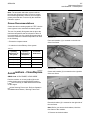
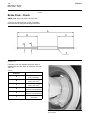
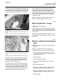
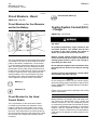
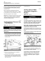
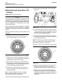
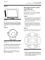
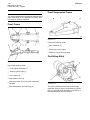
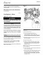
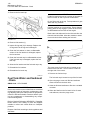
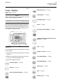
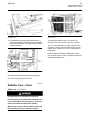
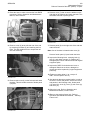
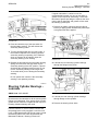
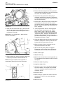
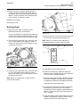
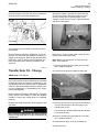
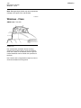
150
Maintenance Section
Seat Belt - Inspect
SEBU8524
i02429589
i02429594
Seat Belt - Inspect
Seat Belt - Replace
SMCS Code: 7327-040
SMCS Code: 7327-510
Always check the condition of the seat belt and the
condition of the seat belt mounting hardware before
you operate the machine. Replace any parts that are
damaged or worn before you operate the machine.
Within three years of the date of installation or within
five years of the date of manufacture, replace the
seat belt . Replace the seat belt at the date which
occurs first. A date label for determining the age of
the seat belt is attached to the seat belt, the seat belt
buckle, and the seat belt retractor.
Illustration 204
g00932801
Typical example
Check the seat belt mounting hardware (1) for wear
or for damage. Replace any mounting hardware that
is worn or damaged. Make sure that the mounting
bolts are tight.
Check buckle (2) for wear or for damage. If the buckle
is worn or damaged, replace the seat belt.
Inspect the seat belt (3) for webbing that is worn or
frayed. Replace the seat belt if the seat belt is worn
or frayed.
Consult your Caterpillar dealer for the replacement of
the seat belt and the mounting hardware.
Note: Within three years of the date of installation or
within five years of the date of manufacture, replace
the seat belt. Replace the seat belt at the date which
occurs first. A date label for determining the age of
the seat belt is attached to the seat belt, the seat belt
buckle, and the seat belt retractor.
If your machine is equipped with a seat belt
extension, also perform this inspection procedure for
the seat belt extension.
Illustration 205
(1)
(2)
(3)
(4)
g01152685
Date of installation (retractor)
Date of installation (buckle)
Date of manufacture (tag) (fully extended web)
Date of manufacture (underside) (buckle)
Consult your Caterpillar dealer for the replacement of
the seat belt and the mounting hardware.
If your machine is equipped with a seat belt
extension, also perform this replacement procedure
for the seat belt extension.
i03581320
Secondary Steering - Test
SMCS Code: 4324-081
Test the secondary steering by using the following
procedure:
1. Park the machine on a hard level surface. Lower
the truck body or OEM attachment and shut off
the engine. Leave the engine start switch in the
ON position.
SEBU8524
151
Maintenance Section
Steering Cylinder Bearings - Lubricate
If regular lubrication is carried out at the
recommended intervals, only one or two shots of
grease will be required at each fitting. If more than
two shots of grease per fitting are required, the lines
may be split or damaged, and grease will not reach
the steering cylinder pins.
1. Remove the plastic caps and clean the fittings
before you apply grease. Reinstall the plastic caps
once grease has been applied.
Illustration 206
g01035886
2. Press and hold the top of the test switch for
the secondary steering. This will activate the
secondary steering motor.
3. Turn the steering wheel fully from left to right. If
the machine responds to the steering input the
secondary steering is operating. If the machine
does not respond to the steering input the
secondary steering is not working.
4. Release the test switch for the secondary steering.
Spring force will return the test switch for the
secondary steering to the OFF position. This will
deactivate the secondary steering motor. Do not
run the secondary steering motor longer than
12 seconds while you are testing the secondary
steering.
Illustration 207
g01126471
2. Lubricate the front steering cylinder bearings
through the fittings on the panel.
Do not operate the machine if the secondary
steering is not operating correctly.
i03581322
Steering Cylinder Bearings Lubricate
SMCS Code: 4303-086-BD
NOTICE
Check that the lines attached to all the remote grease
fittings are undamaged. If the grease lines are split,
grease will not reach the components that require lubricating. Machine damage will result.
Park the machine on a level surface. Ensure that
the parking brake is fully engaged. Lower the truck
body or OEM attachment and stop the engine. Install
the steering frame lock. Refer to Operation and
Maintenance Manual, “Steering Frame Lock”.
Illustration 208
g01126474
3. Lubricate the rear steering cylinder bearings
through fittings on the cylinders.
4. Remove the steering frame locks.
152
Maintenance Section
Suspension System - Check
SEBU8524
i02021470
Suspension System - Check
SMCS Code: 7200-535
i03581325
Suspension and Suspension
Cylinder Bearings - Lubricate
SMCS Code: 7200-086-BD; 7201-086-BD
The suspension system may drop the machine
suddenly leaving no clearance between the axle
housing, main frame, tires, and mud guards.
Working in these areas can result in personal injury or death by crushing.
Park the machine on level ground and block the
front frame before you go under the machine.
1. Disengage the differential locks. Bring the
machine to a gentle stop on firm level ground.
2. Release the service brake. Wait for one second
before applying the parking brake.
3. Install suitable stands under the front frame.
NOTICE
Check that the lines attached to all the remote grease
fittings are undamaged. If the grease lines are split,
grease will not reach the components that require lubricating. Machine damage will result.
Park the machine on a level surface. Engage
the parking brake. Lower the truck body or OEM
attachment and shut off the engine. Install the
steering frame lock. Refer to Operation and
Maintenance Manual, “Steering Frame Lock”.
If regular lubrication is performed at the recommended
intervals, only one or two shots of grease will be
required at each fitting.
1. Clean all the fittings by wiping before you lubricate
the fittings.
Note: The fittings are located behind caps which
require removing in order to access the fittings.
Illustration 209
g01043895
4. Measure distance (A). Distance (A) is the distance
between the mounting pins of the suspension
cylinder. Dimension (A) should be 700 ± 10 mm
(27.6 ± 0.39 inch).
Note: Measure distance (A) when the machine is
cool.
5. If the suspension height is not correct, consult your
Caterpillar dealer. Special tools and procedures
are required in order to adjust the height of the
front suspension.
6. Remove the stands.
Illustration 210
g01126573
2. Lubricate the front suspension cylinder bearings
through fittings (1). Lubricate the spherical bearing
on the front suspension a-frame through fitting (2).
Note: The fittings for lubrication of the front
suspension are located at the rear of the tractor on
the left side.
SEBU8524
153
Maintenance Section
Tire Inflation - Check
• Operation and Maintenance Manual, “Tire Shipping
Pressure”
• Operation and Maintenance Manual, “Tire Inflation
Pressure Adjustment”
i03581346
Torque Converter and
Transmission Oil - Change
SMCS Code: 3030-044-OC; 3101-044-OC
Illustration 211
g01126574
3. Lubricate the spherical bearings on the rear
suspension a-frames through fittings (3).
Note: The fittings for lubrication of the spherical
bearings on the rear suspension a-frames are located
at the front of the trailer on the left side.
4. Install the caps to the fittings.
5. Remove the steering frame lock. Refer to
Operation and Maintenance Manual, “Steering
Frame Lock”.
NOTICE
Care must be taken to ensure that fluids are contained
during performance of inspection, maintenance, testing, adjusting and repair of the product. Be prepared to
collect the fluid with suitable containers before opening any compartment or disassembling any component containing fluids.
Refer to Special Publication, NENG2500, “Caterpillar
Dealer Service Tool Catalog” for tools and supplies
suitable to collect and contain fluids on Caterpillar
products.
Dispose of all fluids according to local regulations and
mandates.
i00062438
Tire Inflation - Check
Hot oil and hot components can cause personal
injury. Do not allow hot oil or hot components to
contact skin.
SMCS Code: 4203-535-AI
Operate the machine until the torque converter and
transmission oil is warm. Park the machine on a level
surface. Engage the parking brake. Lower the truck
body or OEM attachment and shut off the engine.
1. Raise the hood. Refer to Operation and
Maintenance Manual, “Hood Control”.
The oil level dipstick is integral with the oil filler cap
for the torque converter and transmission oil. The
oil filler cap is located near the air cleaner housing.
Illustration 212
g00103147
Measure the air pressure on each tire. Consult your
Caterpillar dealer for the correct load rating and for
the correct operating pressures.
If necessary, inflate the tires. Refer to the following
additional information about tire inflation:
• Operation and Maintenance Manual, “Tire Inflation
with Nitrogen”
154
Maintenance Section
Torque Converter and Transmission Oil - Change
SEBU8524
4. Clean the area around drain plug (5).
5. Remove the drain plug and the O-ring seal and
retain the drain plug and the O-ring seal. Allow the
oil to drain into a suitable container.
6. Inspect the O-ring seal for the drain plug. If
necessary, replace the O-ring seal. Lubricate the
O-ring seal with transmission oil. Install the O-ring
seal and the drain plug.
Illustration 213
g01126900
2. Clean the area around filler cap (1) and filler tube
(2). Turn the handle on the dipstick in order to
remove the dipstick. Remove the dipstick in order
to allow the oil to drain.
Note: Before you change the oil, block the front
frame of the machine.
7. Remove the oil filter for the torque converter and
transmission oil. Discard the oil filter. Install a
new oil filter. Refer to Operation and Maintenance
Manual, “Torque Converter and Transmission Oil
Filter - Replace”.
8. Fill the transmission with new oil through filler
tube (2). Fill the transmission to the “COLD
SAFE START” range on the oil level dipstick.
Refer to the Operation and Maintenance Manual,
“Capacities (Refill)”, Operation and Maintenance
Manual, “Lubricant Viscosities” and Operation
and Maintenance Manual, “Torque Converter and
Transmission Oil Level - Check”.
9. Guide the dipstick down the filler tube and turn the
handle on the dipstick in order to make the seal
between the filler tube and the filler cap.
10. Start the engine. Run the engine at low idle.
Inspect the transmission for leaks.
11. Ensure that the parking brake is engaged.
Engage the service brakes. Slowly operate the
transmission control in order to circulate the oil.
12. Shut off the engine.
Illustration 214
g01127725
3. Remove plate (3) in order to access the drain plug
for the torque converter and transmission oil.
Note: Plate (3) is located on the right side of
transmission guard (4) in front of the front axle.
13. Replace Plate (3).
14. Wait for five minutes before removing dipstick (1).
Turn the handle on the dipstick in order to remove
the dipstick.
15. Clean the dipstick by wiping.
16. Install the dipstick fully.
17. Check the oil level on the COLD SAFE START
side of the dipstick. The engine can be started
if the oil is anywhere within the shaded area. If
necessary, add oil.
18. Lower the hood.
19. Start the engine. Operate the machine until the
temperature of the oil is at normal operating
temperature.
Illustration 215
g01127726
20. Raise the hood.
SEBU8524
155
Maintenance Section
Torque Converter and Transmission Oil - Change
21. Check the torque converter and transmission
oil level on the “FULL HOT LOW IDLE” side of
the dipstick. Refer to Operation and Maintenance
Manual, “Torque Converter and Transmission Oil
Level - Check”. If necessary, add oil.
22. Shut off the engine.
23. Close the hood.
Ecology Drain
1. Raise the hood. Refer to Operation and
Maintenance Manual, “Hood Control”.
The oil level dipstick is integral with the oil filler cap
for the torque converter and transmission oil. The
oil filler cap is located near the air cleaner housing.
2. Clean the area around filler cap (1) and filler tube
(2). Turn the handle on the dipstick in order to
remove the dipstick. Remove the dipstick in order
to allow the oil to drain.
Illustration 217
4. Remove plate (3) in order to access the drain plug
for the torque converter and transmission oil.
Note: Plate (3) is located on the right side of
transmission guard (4) in front of the front axle.
Illustration 218
Illustration 216
g01126900
g01127725
g01127726
5. Clean the area around drain plug (5).
3. Clean the area around filler cap (1) and filler tube
(2). Turn the handle on the dipstick in order to
remove the dipstick. Remove the dipstick in order
to allow the oil to drain.
6. Remove the drain plug. Install 6B-3156 Pipe
Nipple in order to unseat the drain valve. Allow the
oil to drain into a suitable container.
Note: Before you change the oil, block the front
frame of the machine.
7. Remove the pipe nipple. Inspect the drain plug and
the seal for damage. If the drain plug or the seal
are damaged, replace the damaged components.
Install the drain plug and the seal.
8. Remove the oil filter for the torque converter and
transmission oil. Discard the oil filter. Install a
new oil filter. Refer to Operation and Maintenance
Manual, “Torque Converter and Transmission Oil
Filter - Replace”.
9. Guide the dipstick down the filler tube and turn the
handle on the dipstick in order to make the seal
between the filler tube and the filler cap.
156
Maintenance Section
Torque Converter and Transmission Oil Filter - Replace
10. Start the engine. Run the engine at low idle.
Inspect the transmission for leaks.
SEBU8524
i03581363
11. Ensure that the parking brake is engaged.
Engage the service brakes. Slowly operate the
transmission control in order to circulate the oil.
Torque Converter and
Transmission Oil Filter Replace
12. Shut off the engine.
SMCS Code: 3067-510; 3101-510-FI
13. Replace Plate (3).
NOTICE
Care must be taken to ensure that fluids are contained
during performance of inspection, maintenance, testing, adjusting and repair of the product. Be prepared to
collect the fluid with suitable containers before opening any compartment or disassembling any component containing fluids.
14. Wait for five minutes before removing dipstick (1).
Turn the handle on the dipstick in order to remove
the dipstick.
15. Clean the dipstick by wiping.
16. Install the dipstick fully.
17. Check the oil level on the COLD SAFE START
side of the dipstick. The engine can be started
if the oil is anywhere within the shaded area. If
necessary, add oil.
18. Lower the hood.
19. Start the engine. Operate the machine until the
temperature of the oil is at normal operating
temperature.
20. Raise the hood.
21. Check the torque converter and transmission
oil level on the “FULL HOT LOW IDLE” side of
the dipstick. Refer to Operation and Maintenance
Manual, “Torque Converter and Transmission Oil
Level - Check”. If necessary, add oil.
22. Shut off the engine.
Refer to Special Publication, NENG2500, “Caterpillar
Dealer Service Tool Catalog” for tools and supplies
suitable to collect and contain fluids on Caterpillar
products.
Dispose of all fluids according to local regulations and
mandates.
Hot oil and hot components can cause personal
injury. Do not allow hot oil or hot components to
contact skin.
Park the machine on a level surface. Engage
the parking brake. Lower the truck body or OEM
attachment and shut off the engine.
Note: Before you remove the filter, block the front
frame of the machine.
23. Close the hood.
Illustration 219
g01127612
1. Remove the cover in order to access the oil filter
cover.
SEBU8524
157
Maintenance Section
Torque Converter and Transmission Oil Level - Check
i03581366
Torque Converter and
Transmission Oil Level Check
SMCS Code: 3030-535-FLV; 3101-535-FLV
Illustration 220
g01127613
2. Clean the area around drain plug (3). Remove the
drain plug and the O-ring seal and retain the drain
plug and the O-ring seal. Allow the oil to drain into
a suitable clean container.
Note: Approximately 4.5 L (1.2 US gal) will drain from
the transmission when drain plug (3) is removed.
3. Remove oil filter cover (2). Remove the O-ring
seal and retain the O-ring seal.
Note: Note the orientation of cover (2). The cover
must be installed in the position.
4. Remove the nut and the washer that secures the
oil filter to the transmission. Remove the oil filter
and discard the oil filter.
NOTICE
Care must be taken to ensure that fluids are contained
during performance of inspection, maintenance, testing, adjusting and repair of the product. Be prepared to
collect the fluid with suitable containers before opening any compartment or disassembling any component containing fluids.
Refer to Special Publication, NENG2500, “Caterpillar
Dealer Service Tool Catalog” for tools and supplies
suitable to collect and contain fluids on Caterpillar
products.
Dispose of all fluids according to local regulations and
mandates.
The oil level should be checked before starting the
engine.
1. Park the machine on a level surface. Engage the
parking brake and lower the truck body or OEM
attachment.
2. Raise the hood. Refer to Operation and
Maintenance Manual, “Hood Control”.
5. Fit a new oil filter. Fit the washer and the nut in
order to secure the oil filter to the transmission.
6. Inspect the O-ring seal for the oil filter cover. If
necessary, replace the O-ring seal. Lubricate the
O-ring seal with transmission oil. Install the O-ring
seal and oil filter cover (2).
7. Inspect the O-ring seal for drain plug (3). If
necessary, replace the O-ring seal. Lubricate the
O-ring seal with transmission oil. Install the O-ring
seal and install the drain plug.
8. Top up the torque converter and transmission
oil level with the correct oil. Refer to Operation
and Maintenance Manual, “Torque Converter and
Transmission Oil Level - Check” and Operation
and Maintenance Manual, “Lubricant Viscosities”.
Illustration 221
9. Check oil filter cover (2) and drain plug (3)
for leaks. If oil leakage is evident, repeat the
replacement procedure.
Note: The oil level dipstick is integral with the oil filler
cap for the transmission oil. Oil filler tube (2) for the
torque converter and transmission oil is located on
the left side of the machine near the air cleaner.
10. Replace the cover on the transmission guard.
g01126900
3. Wipe oil filler cap (1) and oil filler tube (2).
4. Turn the handle on the oil level dipstick in order to
remove the dipstick. Remove the oil level dipstick.
158
Maintenance Section
Torque Converter and Transmission Oil Sample - Obtain
SEBU8524
17. Check the oil level on the “FULL HOT LOW IDLE”
side of the dipstick. Maintain the oil level within
the shaded area on the dipstick. If necessary, add
oil through filler tube (2). Refer to Operation and
Maintenance Manual, “Lubricant Viscosities” and
Operation and Maintenance Manual, “Capacities
(Refill)”.
5. Clean the dipstick by wiping.
6. Install the dipstick fully.
7. Remove the dipstick.
18. Guide the dipstick down the filler tube and turn
the handle of the dipstick in order to make the seal
between the filler tube and the filler cap.
19. Lower the hood.
i02228028
Illustration 222
g00740027
Note: The oil level dipstick is marked “COLD SAFE
START” on one side. The oil level dipstick is marked
“FULL HOT LOW IDLE” on the other side.
8. Check the oil level on the “COLD SAFE START”
side of the dipstick.
The engine can be started if the oil is anywhere
within the shaded area. Do not add oil if the
level is toward the bottom of the “COLD
SAFE START” shaded area. An oil level that is
anywhere in this range is normal.
9. Guide the dipstick down the filler tube and turn the
handle on the dipstick in order to make the seal
between the filler tube and the filler cap.
Torque Converter and
Transmission Oil Sample Obtain
SMCS Code: 3030-008; 3101-008; 7542-008
NOTICE
Care must be taken to ensure that fluids are contained
during performance of inspection, maintenance, testing, adjusting and repair of the product. Be prepared to
collect the fluid with suitable containers before opening any compartment or disassembling any component containing fluids.
Refer to Special Publication, NENG2500, “Caterpillar
Tools and Shop Products Guide” for tools and supplies
suitable to collect and contain fluids on Caterpillar
products.
Dispose of all fluids according to local regulations and
mandates.
10. Lower the hood.
11. Start the engine. Operate the machine until the
temperature of the oil is at normal operating
temperature.
12. Park the machine on a level surface. Engage the
parking brake.
Hot oil and hot components can cause personal
injury. Do not allow hot oil or hot components to
contact skin.
13. Raise the hood. Wait for five minutes before
removing dipstick (1). Turn the handle on the
dipstick in order to remove the dipstick.
Note: The shaded area on the side of the oil level
dipstick that is marked “FULL HOT LOW IDLE”
indicates the correct transmission oil level. Refer to
illustration 222.
14. Clean the dipstick by wiping.
15. Install the dipstick fully.
16. Remove the dipstick and check the oil level.
Illustration 223
g01127660
SEBU8524
159
Maintenance Section
Transfer Gear Oil - Change
Remove the plate on the left side of the transmission
guard in order to access the sampling port.
Illustration 224
Operate the machine until the oil is warm and the
oil is well circulated. Park the machine on a level
surface. Ensure that the parking brake is fully
engaged. Lower the truck body or OEM attachment
and shut off the engine.
g01127662
The sampling valve is located on the left side of the
transmission.
Refer to Special Publication, SEBU6250, “S·O·S Oil
Analysis” for information that pertains to obtaining a
sample of the engine oil. Refer to Special Publication,
PEHP6001, “How To Take A Good Oil Sample” for
more information about obtaining a sample of the
engine oil.
i03581400
Transfer Gear Oil - Change
Illustration 225
g00740248
Drain plug (1) for the transfer gear is located on the
bottom of the transfer gear case.
Note: Before you change the oil, block the front
frame of the machine.
1. Remove the drain plug and allow the oil to drain
into a suitable container.
2. Clean the drain plug and install the drain plug.
SMCS Code: 3159-044-OC
NOTICE
Care must be taken to ensure that fluids are contained
during performance of inspection, maintenance, testing, adjusting and repair of the product. Be prepared to
collect the fluid with suitable containers before opening any compartment or disassembling any component containing fluids.
Refer to Special Publication, NENG2500, “Caterpillar
Dealer Service Tool Catalog” for tools and supplies
suitable to collect and contain fluids on Caterpillar
products.
Dispose of all fluids according to local regulations and
mandates.
Hot oil and hot components can cause personal
injury. Do not allow hot oil or hot components to
contact skin.
Illustration 226
g00740253
3. Remove bolts (2) and cover (3) from the machine.
This will allow access to the drain plug for the
transfer gear oil tank.
The drain plug is located underneath the machine
on the front left side.
4. Remove the drain plug and allow the oil to drain
into a suitable container.
5. Install the drain plug, cover (3), and bolts (2).
6. Raise the hood.
160
Maintenance Section
Transfer Gear Oil Filter - Replace
SEBU8524
Refer to Operation and Maintenance Manual,
“Hood Control”.
i03581423
Transfer Gear Oil Filter Replace
SMCS Code: 3159-510-FI
Hot oil and hot components can cause personal
injury. Do not allow hot oil or hot components to
contact skin.
Illustration 227
g00702070
7. Oil filler cap (4) for the transfer gear oil tank is
located on the left side of the engine compartment.
The oil level gauge is attached to the oil filler cap.
8. Unscrew and then remove the oil filler cap. Add
the oil for the transfer gear.
Refer to Operation and Maintenance Manual,
“Capacities (Refill)” and refer to Operation and
Maintenance Manual, “Lubricant Viscosities”.
9. Clean the oil level gauge and the oil filler cap.
Install the oil filler cap.
10. Start the engine. Operate the machine until the oil
is at operating temperature. Inspect the transfer
gear case for leaks.
11. Remove the oil filler cap and check the oil level
on the oil level gauge.
Note: Refer to Operation and Maintenance
Manual, “Transfer Gear Oil Level - Check” for more
information.
NOTICE
Care must be taken to ensure that fluids are contained
during performance of inspection, maintenance, testing, adjusting and repair of the product. Be prepared to
collect the fluid with suitable containers before opening any compartment or disassembling any component containing fluids.
Refer to Special Publication, NENG2500, “Caterpillar
Dealer Service Tool Catalog” for tools and supplies
suitable to collect and contain fluids on Caterpillar
products.
Dispose of all fluids according to local regulations and
mandates.
Park the machine on a level surface. Ensure that the
parking brake is fully engaged. Lower the truck body
or OEM attachment and shut off the engine.
Drain the oil before removing the oil filter. Refer to
Operation and Maintenance Manual, “Transfer Gear
Oil - Change” for information on draining the oil.
Note: Before you change the filter, block the front
frame of the machine.
12. Clean the oil level gauge and the oil filler cap.
13. Install the oil filler cap and tighten.
14. Shut off the engine.
15. Clean up oil spills.
16. Lower the hood.
Refer to Operation and Maintenance Manual,
“Hood Control”.
Illustration 228
g00742910
The oil filter for the transfer gear is located on the rear of the tractor
on the right side of the rear frame.
1. Clean the outside of the oil filter for the transfer
gear.
SEBU8524
161
Maintenance Section
Transfer Gear Oil Level - Check
2. Remove the oil filter with a strap type wrench.
Discard the used oil filter properly.
Refer to Operation and Maintenance Manual, “Oil
Filter - Inspect”.
3. Clean the oil filter base.
4. Apply a thin coat of oil to the seal of the new oil
filter.
5. Install the new oil filter by hand. When the seal
contacts the oil filter base, turn the oil filter by 270°
more. This will tighten the oil filter sufficiently.
Illustration 229
g01125860
i03581442
Transfer Gear Oil Level - Check
SMCS Code: 3159-535-FLV; 3159-535-OC
NOTICE
Care must be taken to ensure that fluids are contained
during performance of inspection, maintenance, testing, adjusting and repair of the product. Be prepared to
collect the fluid with suitable containers before opening any compartment or disassembling any component containing fluids.
Refer to Special Publication, NENG2500, “Caterpillar
Dealer Service Tool Catalog” for tools and supplies
suitable to collect and contain fluids on Caterpillar
products.
3. Wipe oil filler cap (1) and oil filler tube (2).
Note: The oil level dipstick is integral with the oil filler
cap for the transfer gear. Oil filler tube (2) for the
transfer gear is located on the left side of the engine
compartment.
4. Turn the handle on the oil level dipstick in order to
remove the dipstick. Remove the oil level dipstick.
5. Clean the dipstick by wiping.
6. Install the dipstick fully.
7. Remove the dipstick.
Dispose of all fluids according to local regulations and
mandates.
Check the oil level before the engine is started.
1. Park the machine on a level surface. Engage the
parking brake and lower the truck body or OEM
attachment.
2. Raise the hood. Refer to Operation and
Maintenance Manual, “Hood Control”.
Illustration 230
g00740112
Note: The oil level dipstick is marked: “MIN COLD”
(3) , “MIN HOT” (4), and “MAX HOT” (5).
8. Check the oil on the dipstick.
Note: The engine can be started if the oil is above
the mark “MIN COLD”(3).
9. If necessary, add oil through filler tube (2) until
the level is at the “MIN COLD” mark. Refer to
Operation and Maintenance Manual, “Lubricant
Viscosities”.
162
Maintenance Section
Transfer Gear Oil Sample - Obtain
SEBU8524
10. Guide the dipstick down the filler tube and turn
the handle on the dipstick in order to make the
seal between the filler tube and the filler cap.
11. Lower the hood.
Hot oil and hot components can cause personal
injury. Do not allow hot oil or hot components to
contact skin.
12. Start the engine. Operate the machine until the
temperature of the oil is at normal operating
temperature.
13. Park the machine on a level surface. Engage the
parking brake. Shut off the engine.
14. Raise the hood. Remove oil level dipstick (1).
15. Clean the dipstick by wiping.
16. Install the dipstick fully.
17. Remove the dipstick.
18. Check the oil level on the dipstick. If the oil is
between the range “MIN HOT” (4) and “MAX HOT”
(5) this is normal. Maintain the oil level within this
area on the dipstick. If necessary, add oil through
filler tube (2). Refer to Operation and Maintenance
Manual, “Lubricant Viscosities”.
19. Guide the dipstick down the filler tube and turn
the handle of the dipstick in order to make the seal
between the filler tube and the filler cap.
20. Close the hood.
i03581500
Transfer Gear Oil Sample Obtain
SMCS Code: 3159-008; 3159-554-OC
NOTICE
Care must be taken to ensure that fluids are contained
during performance of inspection, maintenance, testing, adjusting and repair of the product. Be prepared to
collect the fluid with suitable containers before opening any compartment or disassembling any component containing fluids.
Refer to Special Publication, NENG2500, “Caterpillar
Dealer Service Tool Catalog” for tools and supplies
suitable to collect and contain fluids on Caterpillar
products.
Dispose of all fluids according to local regulations and
mandates.
Illustration 231
g00847341
Location of the sampling valve for the transfer gear
1. Operate the machine until the oil reaches
operating temperature.
2. Park the machine on a level surface. Lower the
truck body or OEM attachment and engage the
parking brake.
3. Shut off the engine.
4. Install the steering frame lock. Refer to Operation
and Maintenance Manual, “Steering Frame Lock”.
Note: Before you obtain a sample of the oil, block the
front frame of the machine.
5. Install the oil drain tube assembly to the sampling
valve.
6. Start the engine.
7. Drain an oil sample from the sampling valve.
8. Shut off the engine.
9. Remove oil drain tube assembly from the sampling
valve.
Use S·O·S oil analysis in order to monitor the
condition of the transfer gear.
SEBU8524
163
Maintenance Section
Wheel Nut Torque - Check
i02889528
Wheel Nut Torque - Check
Perform the following operations in order to access
and fill the window washer reservoir:
1. Park the machine on a level surface. Engage the
parking brake and shut off the engine.
SMCS Code: 4210-535
Check the wheel nut torque on any wheel that has
been mounted or remounted. Continue to check the
wheel nut torque at every 10 service hours or on a
daily basis until the wheel nuts maintain the specified
torque.
2. Raise the hood. Refer to Operation and
Maintenance Manual, “Hood Control”.
3. Remove the filler cap of the reservoir.
4. Fill the reservoir through the filler opening.
5. Replace the filler cap of the reservoir and lower
the hood. Refer to Operation and Maintenance
Manual, “Hood Control”.
i03581520
Window Wiper Inspect/Replace
SMCS Code: 7305-040; 7305-510
Illustration 232
g01125960
Tighten the wheel nuts to a torque of 475 ± 60 N·m
(350 ± 44 lb ft).
Park the machine on a level surface. Engage
the parking brake. Lower the truck body or OEM
attachment and shut off the engine.
i01401274
Window Washer Reservoir Fill
SMCS Code: 7306-544
NOTICE
When operating in freezing temperatures, use
Caterpillar or any commercially available nonfreezing
window washer solvent.
Illustration 234
g00776803
Inspect the front wiper blade. Inspect the rear wiper
blade, if equipped.
Replace a wiper blade when the following conditions
occur:
• The wiper blade is causing streaks on the front
window.
• The wiper blade is causing streaks on the rear
window.
Illustration 233
g00738419
The window washer reservoir is located inside the
engine compartment on the left side.
• The wiper blade is worn.
• The wiper blade is damaged.
164
Maintenance Section
Windows - Clean
SEBU8524
Note: Damaged wiper blades may cause permanent
damage to the glass of the cab windows.
i01495125
Windows - Clean
SMCS Code: 7310-070
Illustration 235
g00776437
Use commercially available window cleaning
solutions and a clean cloth to clean the windows.
Clean the outside of the windows from the ground
unless handholds can be utilized from positions on
the deck.
Use a device with a long handle or steps in order to
clean the windows from the ground.