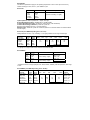
1
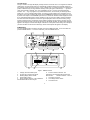
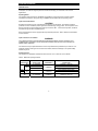
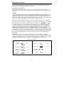
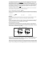
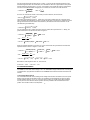
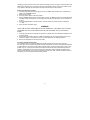
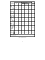
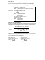
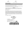
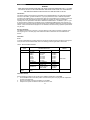
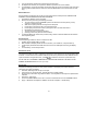
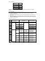
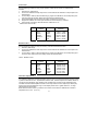
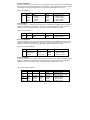
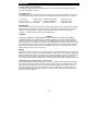
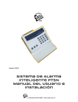
Model BDM40
Bench Digital Multimeter
Be nch Digit a l Mult im e t e r
Operator’s Manual
LIMITED WARRANTY AND LIMITATION OF LIABILITY
Your Meterman product will be free from defects in material and workmanship for 90 days from the date
of purchase. This warranty does not cover fuses, disposable batteries or damage from accident, neglect,
misuse, alteration, contamination, or abnormal conditions of operation or handling. Resellers are not
authorized to extend any other warranty on Fluke’s behalf. To obtain service during the warranty period,
return the product with proof of purchase to an authorized Meterman Test Tools Service Center or to a
Meterman dealer or distributor. See Repair Section above for details. THIS WARRANTY IS YOUR ONLY
REMEDY. ALL OTHER WARRANTIES –WHETHER EXPRESS, IMPLIED OR STATUTORY INCLUDING IMPLIED WARRANTIES OF FITNESS FOR A PARTICULAR PURPOSE OR
MERCHANTABILITY, ARE HEREBY DISCLAIMED. MANUFACTURER SHALL NOT BE LIABLE FOR
ANY SPECIAL, INDIRECT, INCIDENTAL OR CONSEQUENTIAL DAMAGES OR LOSSES, ARISING
FROM ANY CAUSE OR THEORY. Since some states or countries do not allow the exclusion or limitation
of an implied warranty or of incidental or consequential damages, this limitation of liability may not apply
to you.
CERTIFICATIONS AND PRECAUTIONS
This instrument is EN61010-1 certified for Installation Category I -1000V; Pollution Degree II, Class 2. It
may only be used to make measurements on energy limited circuits within equipment. All inputs are
protected against continuous overload conditions up to the limits of each function's stated input protection
(see specifications). Never exceed these limits or the ratings marked on the instrument itself. Always
inspect your Multimeter, test leads and accessories for signs of damage or abnormality before every use.
If an abnormal condition exists (broken or damaged test leads, cracked case, display not reading, etc.),
do not use. Never ground yourself when taking measurements. Do not touch exposed metal pipes,
outlets, fixtures, etc., which might be at ground potential. Keep your body isolated from ground and never
touch exposed wiring, connections, test probe tips, or any live circuit conductors. Do not operate
instrument in an explosive atmosphere (flammable gases, fumes, vapor, dust.) Do not use this or any
piece of test equipment without proper training.
Symbols Used in this Manual
W
X
T
J
B
F
P
G
Refer to the manual
Dangerous voltage
Double Insulation
Earth Ground
Alternating Current
Direct Current
Complies with EU
directives
Diode
This meter is shipped with two power cords. The 117/230
volts power switch on the rear panel has been set to 230
volts and the 0.08A fuse installed.
Please verify the switch and fuse for your location
before installing the power cord
To change to 117 V operation, install proper fuse at
back panel (see manual) and set switch to 117V.
installing the power cord This meter is shipped with two
This instrument is shipped configured for 230 volt operation. Operation at 117 VAC requires that the fuse
be changed and the proper power cord used.
1
FOR UNITED KINGDOM ONLY
NOTE: This lead/appliance must only be wired by competent persons
WARNING: THIS APPLIANCE MUST BE EARTHED
IMPORTANT: The wires in this lead are coloured in accordance with the following code:
E
Green/ Yellow:
Blue:
Brown:
Earth
Neutral
Live (Phase)
N
L
As the colours of the wires in main leads may not correspond with the colours marking identified in your
plug/appliance, proceed as follows: The wire which is coloured Green & Yellow must be connected to the
or coloured Green or Green & Yellow.
Earth terminal marked with the letter E or by the earth symbol
The wire which is coloured Blue must be connected to the terminal which is marked with the letter N or
coloured Blue or Black. The wire which is coloured Brown must be connected to the terminal marked with
the letter L or P or coloured Brown or Red. If in doubt, consult the instructions provided with the
equipment or contact the supplier. This cable/appliance should be protected by a suitably rated and
approved HBC mains fuse : refer to the rating information on the equipment and/or user instructions for
details. As a guide, cable of 0.75 mm should be protected by a 3A or 5A fuse. Larger conductors would
normally require 13A types, depending on the connection method used. Any moulded mains connector
that requires removal / replacement must be destroyed by removal of any fuse & fuse carrier and
disposed of immediately, as a plug with bared wires is hazardous if engaged in live socket. Any re-wiring
must be carried out in accordance with the information detailed on this instruction.
TABLE OF CONTENTS
PAGE
1
1
2
3
5
5
5
8
11
12
13
14
14
14
15
15
16
17
17
17
19
19
19
20
22
WARRANTY
CERTIFICATIONS AND PRECAUTIONS
Introduction
Using your meter
OPERATING GUIDELINES
Introduction
Measurement Techniques
Voltage Measurement
Current Measurement
Resistance Measurement
Diode Measurement
CALIBRATION
Introduction
Calibration
Performance Tests
Display Test
Linear Voltage Test
Current Test
Resistance Test
Calibration Adjustments
MAINTENANCE AND REPAIR INFORMATION
Changing the Input Power Configuration
Repair
SPECIFICATIONS
Optional Accessories
2
INTRODUCTION
This instrument is a line powered, bench-type digital multimeter with a 4-1/2 digit LED display. The DMM
can measure AC/DC volts, AC/DC current, and resistance. Among other features:
True RMS Measurements of AC or AC+DC Signals :
True RMS measurement is the only accurate way to directly measure AC or AC+DC signals that are not
noise-free pure sine waves. This instrument measures AC voltage frequencies up to 50 kHz.
Five measurement functions :
AC and DC VOLTS: Standard linear voltage measurements from 10 µV to 1200 VDC and 10 mV to 1000
VAC or AC+DC true rms.
AC and DC CURRENT: Standard current measurements from 10 nA to 20 ADC and 10 µA to 20 AAC or
AC+DC true rms.
RESISTANCE: Standard resistance measurements from 10 mΩ to 20 MΩ.
Each measurement range has: Autopolarity operation. Overrange indication. Effective protection from
overloads and transients. Dual slope integration measurement technique to insure fast, accurate, noisefree measurements.
Diode test: Ranges of the resistance function that will turn on PN junctions allowing testing of diodes and
transistors. These ranges are marked with a diode symbol on the front panel of your DMM. The preferred
2kΩ range is marked with the largest diode symbol.
Improved test leads: Finger guards on the probes and shrouded contacts on the input terminals
decrease the possibility of accidental contact with circuit voltage.
Long-term calibration accuracy: 1-year.
UNPACKING YOUR INSTRUMENT
The shipping box should contain this manual, your multimeter, test leads (one red and one black), two
spare fuses (2A); two spare fuses 0.08A (230 V) and 0.125A (117 V), and 2 power cords (1 - 115V and
1- 230 V ). Check the shipment for damage.
CAUTION:
This meter has dual operating voltages. It can be operated from 117VAC or 230VAC source. The unit is
shipped in the 230VAC configuration with an T 0.08A / 250 V fuse installed. If you plan to use the BDM40
on a 117 V source, unplug the power cord, switch to the T 0.125A / 250V fuse (supplied with instrument),
and set the rear panel switch to 117V.
If the meter maybe damaged if is not setup properly for the source voltage being used.
The label on the top side of your instrument is marked with the line voltage and frequency required for
proper operation. Refer to Maintenance section if a change in the input power configuration is desired.
GETTING ACQUAINTED
Your meter is light-weight with a low profile, and requires little space on the work bench. The black case
is made of rugged, high-impact plastic. The handle can be rotated to eight positions. The right side of
your DMM contains two rows of switches and LED display. The power cord receptacle is located on the
rear panel of your DMM. The meter inputs are the 4 inputs on the front panel and are marked for the
functions.
USING YOUR METER
The following paragraphs describe each of the controls on your DMM and how these controls can be
used for each instrument function. Exercises are included to help you familiarize yourself with your DMM
and to verify that your instrument is functional.
3
The LED Display
The high-contrast 4-1/2 digit LED display is easily read from across the room. It can register from 0000 to
19999 counts. For ease of discussion, the 19999 will be rounded to 20000 in the remainder of this text.
For example, we will refer to the 2V range, not the 1.9999V range. In all linear functions, the decimal point
position is determined by the range selected. Polarity of the input signal is indicated by a ‘ – ‘ sign at the
center of the left side of the LED. The + sign is disabled in the AC V, AC mA, and kΩ measurement
functions. The ‘ – ‘ sign may appear in any measurement function, but is normally not meaningful when
making AC V, AC mA, and kΩ measurements. You will only get this indication of an energized circuit if
the power in the circuit is negative with respect to the COMMON input terminal. If the power in the circuit
is positive with respect to the COMMON input terminal, an erroneous resistance will be displayed. If there
is any doubt about whether there is energy remaining in the circuit you are reading, read the resistance,
then reverse the test lead positions. If the minus sign is displayed in either case, the remaining energy
must be removed from the circuit before correct resistance readings can be made. If you apply an input
signal that exceeds the limits of the range selected, the LED display will flash. All decimal point positions
appear in the display to indicate certain illegal combinations of front panel switch settings. For example, if
you select the DCV function and the 20M range, all four decimal points will appear on the display.
POWER Switch
The green POWER switch is located in the right corner of the DMM front panel. To turn the meter ON,
push the POWER button in. To turn the meter OFF, push the POWER button in.
1
3
CAT I
1000V
V
Ω
DC 1200V
AC 1000V
BDM40
TRUE
RMS
COM
200mV
500V
MAX
200
DC
mA-2A
2
200uA 2mA
AC
2kG
20
200
1000VAC
1200VDC
POWER
20mA 200mA 2A
20A
20k
20M
200k
2M
20 A
2A MAX
20A MAX
2
4
5
6
8
7
AC MAINS SELECTOR
117 V 230 V
MAINS SUPPLY
FUSE
15 VA MAX 50 Hz / 60 Hz B
117 VAC
230 VAC
105 VAC - 128 VAC
210 VAC - 257 VAC
W
117 VAC
F 0.125 A / 250V
230 VAC
F 0.08 A / 250 V
W
WARNING
T
TO AVOID ELECTRICAL SHOCK
DISCONNECT TEST LEADS AND
POWER CORD BEFORE REMOVING
COVER.
DO NOT OPERATE INSTRUMENT
WITH COVER REMOVED.
TO PREVENT FIRE, REPLACE FUSE
WITH SAME AND RATING
MADE IN TAIWAN
P
SERIAL NO.
9
Figure 1: BDM40 Controls
1. Voltage, Ohms and Diode inputs.
2. Current (mA to 2A) and 20A inputs.
3. Reading display 0000 to 19999.
4. Power button (green).
5. Range selection switches. The pushbuttons
are interlocked with the other ranges.
6. Function selection switches. The
pushbuttons are interlocked with the other two
white function
selection switches A and Ω.
7. Line Power connector.
8. Line Voltage selector switch.
9. Line Power Fuse.
4
OPERATING GUIDELINES
INTRODUCTION
To use your multimeter fully, there are some additional factors to be considered, such as measurement
techniques, the maximum signal input levels that will not damage your instrument, and common
applications.
Operating Notes
The operating notes present the capabilities and limitations of this instrument and routine operator
maintenance instructions. Everyone using an DMM should be familiar with the operating notes.
Input Overload Protection
CAUTION
Exceeding the maximum input overload limits can damage your instrument. The transient overload
protection circuit is intended to protect against short duration high energy pulses. The components used
limit the protection to approximately five pulses per second for 6kV - 10 microsecond pulses, and about
0.6 watts average for lower amplitude pulses .
Each measurement function is equipped with input overload protection. Table 1 lists the overload limits
for each function.
Input Connections to Common
WARNING
TO AVOID ELECTRICAL SHOCK AND/OR INSTRUMENT DAMAGE, DO NOT CONNECT THE
COMMON INPUT TERMINAL TO ANY SOURCE OF MORE THAN 500 VOLTS DC OR PEAK AC
ABOVE EARTH GROUND
This instrument may be operated with the common input terminal at a potential of up to 500V dc or ac
peak with respect to earth ground. If this limit is exceeded, instrument damage or an operator safety
hazard may Occur.
Operating Power
This instrument is available in standard versions that use 117V or 230V AC at 47 to 440Hz
Table 1. Maximum Input Signal Limits
FUNCTION
SELECTED
DC
V
2A
20A
AC
DC or
AC
kΩ
RANGE
SELECTED
INPUT
TERMINALS
ALL RANGES
20V, 200V, 1000V
200mV, 2V
V / Ω and
COMMON
ALL RANGES
mA / 20A and
COMMON
ALL RANGES
V / Ω and
COMMON
5
MAXIMUM INPUT
OVERLOAD
1200VDC or Peak AC
1000VDC or Peak AC
1000Vrms for no longer than 15 sec.
Fuse protected: F 2A / 250V
Not fused
250VDC or VAC rms
MEASUREMENT TECHNIQUES
The information provided here describes techniques In measurement and interpretation of measurements
that may extend the usefulness of your DMM. These techniques, common throughout the electronics
industry, have been tailored specifically for this instrument.
AC Measurement Techniques
When making precise measurements of AC signals, there are special parameters that must be
considered such as the type of AC converter the meter uses (average, rms, etc.), crest factor, bandwidth,
noise, etc.
True RMS
In order to compare dissimilar waveforms, calculate Ohm's law statements or power relationships, you
must know the effective value of a signal. If it is a DC signal, the effective value equals the DC level. If the
signal is AC, however, we have to use the root mean square or rms value. The rms value of an AC
current or AC voltage is defined as being numerically equal to the DC current or voltage that produces the
same heating effect in a given resistance that the ac current or voltage produces.
In the past, average responding converters were the type of converter most widely used. Theoretically,
2 of the peak value and the average value is 2 / pi of the peak
the rms value of a pure sine wave is 1 /
value. Since the meters converted to the average value, the rms value was 1 /
2 ÷ 2 / pi = pi / (2
2) =
1.11 of the average value when measuring a sine wave. Most meters used an average responding
converter and multiplied by 1.11 to present true rms measurements of sine waves. As the signal being
measured deviated from a pure sine wave, the errors in measurement rose sharply. Signals such as
square waves, mixed frequencies, white noise, modulated signals, etc., could not be accurately
measured. Rough correction factors could be calculated for ideal waveforms if the signal being measured
was distortion free, noise-free, and a standard waveform. The true rms converter in your meter provides
direct, accurate measurement of these and other signals. Since this DMM is AC and DC coupled, refer to
the section on Voltage Measurement Techniques for combined AC and DC signal measurements.
Crest Factor
Crest factor range is one of the parameters used to describe the dynamic range of a voltmeter's
amplifiers. The crest factor of a waveform is the ratio of the peak to the rms voltage. In waveforms where
the positive and negative half cycles have different peak voltages, the higher voltage is used in computing
crest factor. Crest factors start at 1.0 for a square wave (peak voltage equals rms voltage).
Figure 2 Crest Factors
WAVE FORM
SQUARE
WAVE
SINE WAVE
TRIANGLE
SAWTOOTH
MIXED
FREQENCIES
CREST FACTOR
WAVE FORM
1.0
CREST FACTOR
SCR OUTPUT
1.414 to 3.0
WHITE NOISE
3.0 to 4.0
AC COUPLED
PULSE TRAIN
3.0
1.414
1.732
SPIKE
1.414 to 2.0
6
> 9.0
Your instrument has a crest factor range of 1.0 to 3.0 at full scale. Going down from full-scale, the crest
factor capability increases from 3.0 to: Full-Scale x 3 (i.e. 6 at half-scale) RMS Value , If an input signal
has a crest factor of 3.0 or less, voltage measurements will not be in error due to dynamic range
limitations at full-scale. If the crest factor of a waveform is not known, and you wish to know if it falls within
the crest factor of your meter, measure the signal with both your meter and an ac coupled oscilloscope. If
the rms reading on your meter is 1/3 of the peak voltage on the waveform or less, then the crest is 3.0.
For readings at less than full-scale, use the preceding formula to determine the maximum crest factor. At
half-scale the maximum crest factor is: 2 x 3 = 1
The waveforms in Figure 2 show signals with increasing values of crest factor. As you can see from the
series of waveforms, a signal with a crest factor above 3.0 is unusual.
(1/ D) − 1
For an ac coupled pulse train: Crest Factor =
Where D = duty cycle or the ratio of pulse width to cycle length. Reversing this formula, we find that your
meter can accurately measure pulse trains at full-scale with a duty cycle above 10% without being limited
by crest factor .
Crest Factor = 3.0 = (1/D) − 1 :
9.0 = (1/D) - 1 :
10.0 = 1/D
Bandwidth
Bandwidth defines the range of frequencies where the response of the voltmeter's amplifiers is no more
than 3 dB down (half-power levels). Your instrument has a bandwidth of greater than 200kHz.
Slew rate
Slew rate is also called the rate limit or the voltage velocity limit. It defines the maximum rate of change of
the output of the amplifiers for a large input signal. Slew rate limitations are not a factor in measuring
voltages within specified frequencies and amplitude limits of this DMM.
Rise and fall time effect on accuracy
The rise and fall time of a waveform are the length of time it takes a waveform to change between the
points that are 10% and 90% of the peak value. When discussing these periods, we'll only mention rise
time. Errors due to rise to fall time can be caused either by bandwidth or slew rate limitations. Slew rate
should not affect your measurement with this DMM.
Figure 3 Waveform Distortion
Ideal
DC Level
t1
Distortion
DC Level
50usec
t1 + t0
1.75usec
A
A
DC Level
t0
T
1.75usec
t1
Components
DC Level
48.25
usec
100usec
Example
An approximate way of converting bandwidth to rise time limit is to divide 0.35 by the 3 dB down
frequency. For your instrument this will be 0.35/200kHz = 1.75 µsec. The following example will help you
calculate errors due to this limitation when measuring rectangular pulses. These calculations will be
rough because ideal waveforms are used in the analysis.
Ideally, the rectangular pulses would have zero rise and fall time and would be the right angled waveform
shown in Figure 3. In practice, every waveform has a rise and fall time and looks more like the waveform
in Figure 3. When calculating the error caused by the bandwidth of your Instrument, we will assume that
7
the rise and fall time equals the slew rate of 1.75 µsec. To do this we will calculate the values for the
theoretical signal with zero rise and fall time, then calculate the values for a signal with the same period
but with total slope periods equal to 1.75 µsec. A comparison of the results will show the measurement
error due to the finite bandwidth. Using Figure 3 for a reference, the total rms and DC levels are :
V Total rms = A
3 t 0 + 2 t1
t +t
V DC = A 0 1
T
3T
Since we can calculate two values, to find what your meter measures, use the formula:
VAC rms = (V total rms) 2 − (V DC)2
Let's look at the waveform in Figure 3. When using your meter to measure the AC component of the
signal, the display will indicate the rms value of the AC signal riding on the DC level. (This DC level is the
average value of the waveform relation to the baseline.) The total rms value of the waveform can be
calculated using the relationship:
V Total rms = (VAC rms) 2 + (V DC)2
For our example let's use a 10kHz pulse train of 50 µsec pulses with a peak value of 1 V. Ideally, the
pulses would have a zero rise time as shown in Figure 3.
V Total rms =
V DC =
3(50) + 2(0)
=
3(100)
150
= 0.5 = 0.707
300
50 + 0
50
=
= 0.5
100
100
V AC rms = (0.707) 2 − (0.5) 2 = 0.50 − 0.25 = 0.25 = 0.5
When the maximum distortion in rise time of 1.75 µsec is assumed, the signal becomes the isosceles
trapezoid waveform shown in Figure 3. In this case:
V Total rms =
V DC =
3(48.25) + 2(1.75)
144.75 + 3.5
148.25
=
=
= 0.494 = 0.703
3(100)
300
300
48.25 + 1.75
50
=
= 0.5
100
100
V AC rms = (0.703) 2 − (0.5) 2 = 0.494 − 0.25 = 0.244 = 0.494
Note that the V DC stayed the same. So, the errors are:
V total rms: = -0.6%:
V AC rms: = -1.2%
VOLTAGE MEASUREMENTS
Your DMM can make either linear voltage or AC + DC TRUE RMS voltage measurements. For both types
of measurements, plug the black test lead into the COMMON terminal and the red test lead into the V-Ω
terminal.
Linear Voltage Measurements
The controls and terminals used for making linear voltage measurements are located on the front panel.
Starting at the top left is the ACV/DCV switch. This pushbutton is interlocked with the other two white
function selection switches A and Ω. If the DCV function switch is in the IN position (DCV selected),
and any other function selection switch is pushed, the DCV pushbutton will be released to the OUT
position. Push the DCV switch to the IN position.
8
The light grey area around the ACV / DCV switch is extended up and to the right to enclose the five range
values of the voltage function. Push the range switch immediately above the value to be measured. The
range selection switches are interlocked in the same manner as the function switches.
Perform the following procedure:
1. If the test leads are not connected, plug them into your DMM: red test lead to the V-Ω terminal and
black to the COMMON terminal.
2. Select the 0.2V range.
3. Push the function switch to the DCV position.
4. With the POWER switch set to the OFF position, connect your DMM to a line power outlet rated at the
operating voltage and frequency of your instrument. Keep the probe tips apart, and not connected to
a circuit.
5. Push the POWER switch to the ON position. The LED should count down rapidly to a reading of
< ± .0020.
6. Select the ACV and 1000V range.
WARNING
LOCAL LINE VOLTAGE IS MEASURED IN THE FOLLOWING STEP. BE CAREFUL NOT TO TOUCH
THE PROBE TIPS WITH YOUR FINGERS OR TO ALLOW THE PROBE TIPS TO TOUCH EACH
OTHER.
7. Insert the probe tips of the test leads into the slots of a power outlet. The LED should display the true
local line voltage.
8. Push the DCV push-button switch. The LED should display near zero volts but there may be some
residual dc voltage on the power line due to non-linear loads such as SCR light dimmers.
9. Remove the test leads from the line power outlet.
Converting voltage measurements
Your instrument is one of a family of DMMs that actually measure the true rms value of an AC or
AC + DC signal. This is a feature that allows accurate measurement of common waveforms like distorted
or mixed frequency sine waves, square waves, sawtooth waves, noise, pulse trains (with a duty cycle of
at least 10%), etc. In the past, the methods used for AC measurement have introduced large errors in
readings. Unfortunately, we've all grown used to these erroneous voltage readings and depend upon
them to indicate whether or not a piece of equipment is working correctly. The data contained in Table 2
should help you convert between measurement methods.
9
PEAK VOLTAGES
AC COUPLED
INPUT
WAVEFORM
METERED VOLTAGE
AC COMPONENT ONLY
DC AND AC
TOTAL RMS
RMS CAL
AC
TRUE RMS
DC
COMPONENT
ONLY
1.414
1.000
0.000
0.000
1.000
1.414
1.414
0.421
0.435
0.900
1.000
2.000
2.000
0.764
0.771
0.636
1.000
2.000
1.000
1.110
1.000
0.000
1.000
1.414
1.414
0.785
0.707
0.707
1.000
2.000
2.000
2.22
K
2K
2D
3.464
1.732
.960
1.000
0.000
PK PK
0 - PK
2.828
TRUE RMS =
ac 2 + dc 2
SINE
PK
0
PK - PK
RECTIFIED SINE
(FULL WAVE)
PK
PK - PK
0
RECTIFIED SINE
(HALF WAVE)
PK
PK - PK
0
SQUARE WAVE
PK
0
PK - PK
SQUARE WAVE
RECTIFIED
PK
PK - PK
0
RECTANGULAR
PULSE
PK
PK - PK
X
0
Y
2
D
D=X/Y
K=
D-D
2
TRIANGLE
SAWTOOTH
PK
0
PK - PK
* RMS CAL IS DISPLAYED VALUE FOR AVERAGE RESPONDING METERS THAT ARE CALIBRATED TO
DISPLAY RMS FOR DINE WAVES
** Your Digital Multimeter
Table 2. Voltage Conversion
10
1.000
Circuit loading error
Connecting most voltmeters to a circuit may change the operating voltage of the circuit if it loads the
circuit down. As long as the circuit resistance (source impedance) is small compared to the input
impedance of the meter, the error is not significant. For example, when measuring voltage with your
meter, as long as the source impedance is 1 kΩ or less, the error will be ≤ .01 %. If circuit loading does
present a problem, the percentage of error can be calculated using the appropriate formula in Figure 4.
Figure 4. Circuit
Loading Error
1. DC Voltage Measurements
Loading Error in % = 100 x Rs / (Rs + Rin)
Where: Rs = Source resistance in ohms of the circuit being measured.
7
Rin = Meter input resistance (1 x 10 ohms)
2. AC Voltage Measurements
First determine input impedance as follows:
10 7
Zin =
1 + (2πFC)2
Where:
Zin = effective input impedance
7
Rin = 10 ohms
-12
Cin = 100 x 10 Farads
F= Frequency in Hz
Then determine source loading error as follows:
Zs
Loading Error in % = 100 x
Zs + Zin
Where:
Zs = Source impedance
Zin = input impedance
* Vector algebra required
Combined AC and DC signal measurements
The waveform shown in Figure 5 is a simple example of an AC signal riding on a DC level. To measure
waveforms such as these, first measure the rms value of the AC component using the AC function of your
meter. Measure the DC component using the DC function of your instrument. The relationship between
the total rms value of the waveform and the AC component and the DC component is:
RMS Total = (AC component rms)2 + (DC component) 2
Figure 5.
RMS Values
AC COMPONENT
DC LEVEL
0V
Insignificance of inherent meter offset
If you short the input of your meter while the AC voltage function is selected, you should have a reading
of less than 10 digits on the display. This small offset is caused by the action of amplifier noise and offset
of the true rms converter. This offset will not significantly affect any readings until you try to measure
signals almost at the lower limit of the meter. For example:
Given: An offset of 40 digits
0.40mV in 200 mV range
Input signal = 10mV in 200 mV range
Given: An offset of 20 digits
0.20mV in 200 mV range
Input signal = 10mV in 200 mV range
Total rms = 102 + 0.42
Total rms = 10 2 + 0.2 2
= 100 + 0.16
= 100 + 0.04
11
= 100.16
= 10.01 mV
= 100.04
= 10.00 mV
The error will be about 0.01mV
the error is not significant
CURRENT MEASUREMENTS
All of the controls and terminals used to make current measurements are located on the front panel. The
AC mA and DC mA function switches determine the measurement function. The colored area around the
20A switch extends up and to the right to enclose the six range values for the 20A measurement function.
Push the range switch immediately above the value to be measured.
As the colored areas around the terminals indicate, the red test lead should be plugged into the 2A or 20A
terminal and the black test lead should be plugged into the COMMON terminal.
WARNING
INSTRUMENT DAMAGE AND OPERATOR INJURY MAY RESULT IF THE FUSE BLOWS WHILE
CURRENT IS BEING MEASURED IN A CIRCUIT WHICH EXHIBITS AN OPEN CIRCUIT VOLTAGE
GREATER THAN 600 VOLTS.
Burden voltage error
When a meter is placed in series with a circuit to measure current, you may have to consider an error
caused by the voltage drop across the meter (in this case, across the protective fuses and current
shunts). This voltage drop is called burden voltage. The maximum full scale burden voltages for your
instrument are: 0.3V for the four lowest ranges, and 0.9V for the 2000mA, 20A ranges. These voltage
drops can affect the accuracy of a current measurement if the current source is unregulated and the
resistance of the shunt and fuse represents a significant part ( 1/ 1000 or more) of the source resistance.
If burden voltage does present a problem, the percentage error can be calculated using the formula
below. This error can be minimized by selecting the highest current range that provides the necessary
resolution.
Calculating Burden Voltage Error
IM
ES
RL
EB
AMMETER SHUNT
Es = Source voltage
RL = Load resistance + Source resistance
IM = Measured current (display reading in amps)
EB = Burden voltage (calculated) , i.e.,
Reading
)
Full Scale
times full scale burden voltage for selected range. See table.
Display reading expressed as a % of full scale (100 x
RANGE F.S.
200µA to 200mA
2000mA
20A
BURDEN VOLTAGE
0.3V max.
1V max.
2V max.
12
Maximum current error due to Burden Voltage
EB
E −I
in % = 100 x
in milli Amps = 100 x B M
E S − EB
E S − EB
Examples: Es = 14V, RL = 9Ω, IM = 1497.mA,
1497.0
EB = 100 x
x1.0 = 74.9% of 1.0 = 0.749V
2000.0
.749
.749
Maximum error in % = 100 x
= 100 x
= 5.06%
14 .749
13.251
Increase displayed current by 5.65% to obtain true current.
Maximum error .749x1497 1121.2
=
=
= 84.6mA
in milli Amps
14 − .749
13.251
Increase displayed current by 84.6mA to obtain true current.
RESISTANCE MEASUREMENTS
The controls and terminals used to make resistance measurements are located on the front panel. The
measurement function is selected by pushing the kΩ switch to the IN position. The colored area enclosing
the kΩ function switch extends up and to the right enclosing the six range values for the resistance
function. To select a particular resistance range, push the range switch immediately above the value to be
measured. Connect the test leads; red to the V-Ω terminal and black to the COMMON terminal.
Use the following procedure to familiarize yourself with the resistance function and to see how the range
switches affect decimal point position on the LED.
1. With the test leads held apart, select the 2000 kΩ range. The LED should display an over range
indication (all digits are flashing).
2. Make a firm connection between the probe tips of the test leads. The LED should count down to
000.0.
3 Maintain a firm contact between the probe tips and sequentially select all ranges starting with the
200Ω range. The decimal point for each should be as follows:
Range
200Ω
2 kΩ
20 kΩ
200 kΩ
2000 kΩ
20 MΩ
Display
199.99*
1.9999*
19.999
199.99
1999.9
19.999
*Display value will show lead resistance.
Automatic test lead compensation
When measuring low resistances, test lead resistance interferes with low resistance readings and usually
has to be subtracted from resistance measurements for accuracy.
DIODE MEASUREMENT
The five resistance ranges bar with a diode symbol beside the range value have a high enough
measurement voltage to turn on a silicon junction. These ranges can be used to check silicon diodes and
transistors. The 2kΩ range is preferred. It is marked with the largest diode symbol.
13
CALIBRATION
WARNING
THESE SERVICING INSTRUCTIONS ARE FOR USE BY QUALIFIED PERSONNEL ONLY. TO AVOID
ELECTRICAL SHOCK, DO NOT PERFORM ANY SERVICING OTHER THAN THAT CONTAINED IN
THE OPERATING INSTRUCTIONS UNLESS YOU ARE QUALIFIED TO DO SO.
Introduction
This section contains the maintenance information for this Digital Multimeter. This information is divided
into service information, general maintenance, a group of performance tests, a calibration adjustment
procedure, and troubleshooting. The performance tests are recommended as an acceptance check when
the instrument is first received and should be completed as necessary to verify that your DMM is
operating within the specification limits listed in SPECIFICATIONS Section. A calibration cycle of 1- year
is recommended to maintain the specifications given in SPECIFICATIONS Section of this manual. The
test equipment required for both the performance test and the calibration adjustment procedure is listed in
Table 3. If the recommended test equipment is not available, instruments having equivalent specifications
may be used.
Service Information
This DMM is warranted for a period of 1-year upon delivery to the original purchaser. Conditions of the
warranty are given on the first page of this manual and Service instructions are in the Maintenance
Section.
Calibration
NOTE:
To avoid contaminating the pcb with grease from the fingers, handle the pcb by its edges or wear gloves.
If the pcb does become contaminated, refer to the cleaning procedure given later in this section.
Table 3. Recommended Calibration
INSTRUMENT
TYPE
Calibrator
Calibration
Leads
DC Volts
AC Volts
100Hz
200Hz
1 kHz
10 kHz
20 kHz
50 kHz
DC Current
AC Current
REQUIRED
CHARACTERISTICS
0 to 1000V
RECOMMENDED
MODEL
± 0.006 %
0 to 750V
± 0.06 %
0 to 2V
± 0.06 %
0 to 750V
± 0.06 %
0 to 100V
± 0.06 %
0 to 100V
± 0.1 %
0 to 20V
± 0.5 %
0 to 2000mA
± 0.05 %
0 to 19mA, 100 Hz
± 0.1 %
100 Ω, 1 kΩ
± 0.01 %
10 kΩ, 100 kΩ
± 0.005 %
Resistance
1MΩ, 10MΩ
± 0.05 %
24 “ shielded cable with a double banana plug at both
ends
Fluke 5500
Pomona 2BC-24
Calibration Access
Use the following procedure to gain access to the calibration adjustments of this DMM.
1. Set the POWER switch to the OFF position and remove the power cord plug from the receptacle in
the rear of the instrument.
2. Remove the Phillips screw from the Bottom of your DMM.
3. Grasp the front panel and slide the instrument out of the case.
14
4.
5.
6.
Turn the instrument upside down as viewed from the front panel.
All adjustments necessary to complete the calibration procedure are now accessible.
For reassembly, reverse the procedure (be careful to align the grooves in the sides of the front panel
with the guides located inside the case and to bend the flexible interconnect inwards and out of the
way).
Main PCB Access
Use the following procedure to gain access to all the components and test points ON THE MAIN PCB
ASSEMBLY FOR TROUBLESHOOTING AND REPAIRING.
1. Complete the calibration access procedure.
2. Remove the front panel using the following procedure:
a. The V-Ω input line and the COMMON input line are attached to the front panel by a snap
connector. Unplug these lines.
b. Slide the fuse spring forward to the edge of the slide panel.
c. Pull the wire up through the slot in the fuse holder barrel.
d. Pull the spring and the fuse contact up through the hole in the fuse holder barrel.
e. Reinstall the fuse and fuse holder.
f.
Turn the instrument component-side-down.
g. Carefully pull the front panel free of the switches.
3. To install the Main PCB, reverse this procedure, being careful to install the PCBs and the shields in
their respective guides.
Display Access
Use the following procedure to remove or replace the LED:
1. Carefully lay the display PCB to one side.
2. Both the Main and Display PCBs should now be flat on your workbench, component-side-up.
3. Tilt the Display PCB towards the Main PCB, and remove the shield plate connecting the Display
PCB.
4. For reassembly, reverse this procedure.
Performance Tests
The performance tests are used to compare the performance of this instrument to the specifications listed
in Section 1 of this manual. If the instrument fails any portion of the performance tests, calibration and/or
repair is indicated. Throughout the tests, your DMM will be referred to as the UUT (Unit Under Test).
NOTE
ALLOW THE UUT TO WARMUP A MINIMUM OF 5 MINUTES AND CONDUCT THE TESTS AT AN
AMBIENT TEMPERATURE OF 23 ± 5°C (73 ± 9°F).
Display Test
Complete the following procedure to verify proper operation of the display annunciators and each
segment of each digit in the display:
1. Select kΩ, 200Ω range with an open circuit input.
2. Verify that for over range indication, the LED will flash in all digit locations.
3. Short the input, select each range listed in Table 4. and verify that the decimal point is positioned as
indicated.
4. Select DC V, 200V range.
5. Connect the DMM Calibrator to the UUT: HI to the V-Ω terminal and LO to the COMMON terminal.
6. Apply + 188.88VDC and adjust the calibrator until the UUT displays + 188.88 exactly.
15
Table 4. Display Test
SELECT
DISPLAY
RANGE
00.00*
200Ω
.0000*
2kΩ
0.000
20kΩ
00.00
200kΩ
000.0
2000kΩ
0.000
20MΩ
*The least significant digit(s) may change by several digits from zero, depending on your test lead
resistance.
Linear Voltage Test
Use the following procedure to verify the proper operation of both the AC and DC V functions:
1. Select DC V, 200mV range.
2. Connect the calibrator HI volts output to the V-Ω terminal and the calibrator LO volts output to the
COM terminal.
3. For each step of Table 5, set the ACV/DCV switch to the indicated position, select the listed range,
program the calibrator for the corresponding input to the UUT, and verify that the UUT display value
lies within the indicated limits.
Table 5. Linear Voltage Test
STEP
UUT SWITCH
POSITIONS
FUNCTION
1
2
3
4
5
6
7
8
9
10
11
12
13
14
15
16
17
18
19
20
21
22
DCV
RANGE
UUT INPUT
LEVEL
DISPLAY READING
FREQUENCY
200mV
+190mVDC
-190mVDC
+189.90 to +190.10
-189.90 to -190.10
2V
+1.9VDC
-1.9VDC
+18990 to +1.9010
-1.8990 to -1.9010
20V
200V
1200V
2V
+19VDC
+190V DC
+1000VDC
Short
+18.990 to +19.010
+189.90 to +190.10
+999.3 to +1000.7
<.0020
200mV
190mVAC rms
100mVAC rms
2V
1.9VAC rms
20V
19VAC rms
200V
190VAC rms
100VAC rms
100V
1000VAC rms
AC V
16
100 Hz
10kHz
50kHz
188.90 to 191.10
188.90 to 191.10
180.20 to 199.80
1kHz
99.35 to 100.65
100Hz
10kHz
50kHz
1.8890 to 1.9110
1.8890 to 1.9110
1.8020 to 1.9980
100Hz
10kHz
50kHz
100Hz
10kHz
18.890 to 19.110
18.890 to 19.110
18.020 to 19.980
188.90 to 191.10
99.35 to 100.65
100Hz
1kHz
993.5 to 1006.5
993.5 to 1006.5
Current Test
Use the following procedure to verify proper operation of both the AC and DC mA measurement
functions:
1. Select DC mA, 200µA range.
2. Connect the calibrator HI amps output to the V-Ω terminal and the calibrator LO amps output to the
COM terminal.
3. For each step in Table 6, select the listed range, program the calibrator for the corresponding UUT
input, and verify that the UUT display value lies within the indicated limits.
4. Set the FUNCTION switch to the AC mA position and select the 20 mA range.
5. Program the calibrator for a UUT input of 19.000 mA rms at a frequency of 100 Hz.
6. Verify that the UUT display value lies between 18.890 and 19.110.
Table 6. Direct Current Test
STEP
1
2
3
4
5
6
SELECT
RANGE
200µA
2mA
20mA
200mA
2000mA
20A
INPUT
190µA
1.9mA
19mA
190mA
1900mA
19A
DISPLAY
READING
189.61 to 190.39
1.8961 to 1.9039
18.961 to 19.039
189.61 to 190.39
1894.1 to 1905.9
18.941 to 19.059
Resistance Test
Use the following procedure to verify the accuracy of the kΩ measurement function:
1. Select kΩ, 200Ω range.
2. Connect the calibrator HI ohms output to the V-Ω terminal and the calibrator LO ohms output to the
COM terminal.
3. For each step in Table 7, select the listed range, program the calibrator for the corresponding input
to the UUT and verify that the UUT display is within the indicated limits.
Table 7. Resistance Test
STEP
1
2
3
4
5
6
7
SELECT
RANGE
200Ω
200Ω
2kΩ
20kΩ
200kΩ
2000kΩ
20MΩ
INPUT
Short
100Ω
1 kΩ
10kΩ
100kΩ
1000kΩ
10MΩ
DISPLAY
READING
00.00 to 00.07
99.86 to 100.14
.9988 to 1.0012
9.988 to 10.012
99.88 to 10.012
997.3 to 1002.7
9.973 to 10.027
Calibration Adjustments
The calibration adjustment procedure should be used any time your instrument has been repaired or fails
to pass the Performance Test. Adjust R306A, R336A if U301, U308 are replaced or if VR302, VR304 do
not have enough adjustment range. Replace U501 if VR502 does not have enough adjustment range.
The RMS Converter Offset Adjustment should not normally need to be done. Adjust only if VR501 (AC)
does not have enough adjustment range or if the display reads .0010 or greater with AC V, 2V range
selected and the input shorted.
NOTE Allow the UUT to warm up a minimum of 5 minutes and conduct the calibration at an ambient
temperature of 23 ± 5°C (73 ± 9 °F).
17
DC Voltage Calibration
On the UUT select DC V, 2V range, and connect the calibrator HI volts output to the V-Ω terminal and the
calibrator LO volts output to the COM terminal. For each step in Table 8, select the listed range, program
the calibrator for the corresponding UUT input, and make the specified adjustment or check.
Table 8. DC Calibration
Step
1
2
3
4
5
Range
200mV
2V
200mV
200V
1000V
Input
Short
+ 1.9000V
+ 190.00mV
+ 190.00V
+ 1000.0V
Adjust
VR303
VR302
VR304
VR202
VR203
Display Limits
Less than ± 00.04
+ 1.9000V exactly
+ 190.00mV exactly
+ 190.00V exactly
+ 1 000.0V exactly
Ohms Calibration
On the UUT select ‘ Ω ‘, 200Ω range, and connect the V-Ω terminal to the calibrator HI ohms output and
COM to the calibrator LO ohms output. For each step in Table 9, select the listed range, program the
calibrator for the corresponding UUT input, and make the specified adjustment or check.
Table 9. Ohms Calibration
Step
1
2
Range
20 MΩ
20 kΩ
Input
10 MΩ
10 kΩ
Adjust
VR402
VR401
Display Limits
9.995 to 10.005
9.998 to 10.002
DC Current Calibration
On the UUT select DC, 20 A range, and connect the 20A terminal to the calibrator HI amps output and
COM to the calibrator LO amps output. For each step in Table 10, select the listed range, program the
calibrator for the corresponding UUT input, and make the specified adjustment or check.
Table 10. DC Current Calibration
Step
1
2
3
Range
20 A
2 A (2000mA)
200 mA
Input
+ 1.9 A
+ 1.9 A
+ 190.00 mA
Adjust
VR206
VR205
VR204
Display Limits
+ 1.898 to 1.902
+ 1899.8 to 1900.2
+ 189.98 to 190.02
AC Volts Calibration
On the UUT select AC only, 2 V range, and connect the V-Ω terminal to the calibrator HI volts output and
COM to the calibrator LO volts output. For each step in Table 11, select the listed range, program the
calibrator for the corresponding UUT input, and make the specified adjustment or check.
Table 11. AC Voltage Calibration
Step
1
2
3
4(a)
(b)
5(a)
(b)
Range
2V
Input
Short
Freq.
2V
1.9000V
400Hz
200V
20V
1000v
20V
100.00V
19.000V
1000.0v
19.000V
1 kHz
10 kHz
1 kHz
10 kHz
Adjust
VR501
VR502
SVC202/203
SVC201
SVC202
SVC201
SVC203
18
Display Limits
Less than .0010
1.8995 to 1.9005
ADJ to mechanical center
99.90 to 100.10
18.990 to 19.010
999.5 to 1000.5
18.990 to 19.010
MAINTENANCE
Changing Input Power Configuration
This meter was shipped with power cords and fuses for 117V (USA) and 230V (European) operation.
The initial configuration is for 230V.
Fuse Replacement
This DMM has two fuses. The main power fuse is 0.08A or 0.125A, 250V for line protection. The current
measurement fuse is 2A / 250V for below 2A current measurements (unscrew the mA – 2A input jack).
117 Line Fuse
T 0.125A / 250V
230V Line Fuse
T 0.08A / 250V
2A Current Input Fuse F 2A / 250V
Bussmann GDB-125mA
Bussmann GDB-80mA
Bussmann GMA-2A
Littel Fuse 218.125
Littel Fuse 218.080
Littel Fuse 216.002
MAINTENANCE
If there appears to be a malfunction during the operation of the Multimeter, the following steps should be
performed in order to isolate the cause of the problem: •Review the operating instructions for possible
mistakes in operating procedure. •Inspect and test the Test Cables for a broken or intermittent
connection. • Inspect and test the fuse. See Fuse Replacement.
CLEANING
CAUTION
DO NOT USE AROMATIC HYDROCARBONS OR CHLORINATED SOLVENTS FOR CLEANING.
THESE SOLUTIONS WILL REACT WITH THE PLASTIC MATERIALS USED IN THE INSTRUMENT.
Clean the front panel and case with a mild solution of detergent and water. Clean dust from the circuit
board with clean, dry, low pressure air (20 psi or less). Contaminants can be removed from the pcb using
demineralized water and a soft brush (remove the display assembly before washing the Main PCB and
avoid getting excess amounts of water on the switches). Dry with clean, dry, low pressure air and then
bake at 50 to 60°C (122 to 140°F) for 24 hours.
REPAIR
All test tools returned for warranty or non-warranty repair or for calibration should be accompanied by the
following: your name, company’s name, address, telephone number, and proof of purchase. Additionally,
please include a brief description of the problem or the service requested and include the test leads with
the meter. Non-warranty repair or replacement charges should be remitted in the form of a check, a
money order, credit card with expiration date, or a purchase order made payable to Meterman Test Tools.
In-Warranty Repairs and Replacement – All Countries
Please read the warranty statement that follows, and check your batteries and fuses before requesting
repair. During the warranty period any defective test tool can be returned to your Meterman Test Tools
distributor for an exchange for the same or like product. Please check the “Where to Buy” section on
www.metermantesttools.com for a list of distributors near you. Additionally, in the United States and
Canada In-Warranty repair and replacement units can also be sent to a Meterman Test Tools Service
Center (see below for address).
19
Non-Warranty Repairs and Replacement – US and Canada
Non-warranty repairs in the United States and Canada should be sent to a Meterman Test Tools Service
Center. Call Meterman Test Tools or inquire at your point of purchase for current repair and replacement
rates.
In USA
Meterman Test Tools
1420 75th Street SW
Everett, WA 98203
Tel: 888-993-5853
Fax: 425-446-6390
In Canada
Meterman Test Tools
400 Britannia Rd. E. Unit #1
Mississauga, ON L4Z 1X9
Tel: 905-890-7600
Fax: 905-890-6866
Non-Warranty Repairs and Replacement – Europe
European non-warranty units can be replaced by your Meterman Test Tools distributor for a nominal
charge. Please check the “Where to Buy” section on www.metermantesttools.com for a list of
distributors near you.
European Correspondence Address*
Meterman Test Tools Europe
P.O. Box 1186
5602 BD Eindhoven
The Netherlands
* (Correspondence only – no repair or replacement available from this address. European customers
please contact your distributor.)
SPECIFICATIONS
GENERAL:
o
Temperature Coefficient: < 0.1 times the applicable accuracy specification per C for 0°C to 18°C and
28°C to 50°C (32°F to 64.4°F and 82,4°F to 122°F).
Operating Temperature: 0°C to 50°C (32°F to 122°F).
Storage Temperature: -10°C to +70°C (-14°F to + 158°F).
Relative Humidity: Up to 90%, 0°C to 35°C (32-95°F); up to 70%, 35°C to 50°C (95-122°F),
except on 2000kΩ and 20MΩ, ranges: up to 80%, 0°C to 35°C (32-95°F).
Environmental: Intended for Indoor use. Altitude up to 2000m.
Maximum Common Mode Voltage: 500VDC, or peak AC (low terminal potential with respect to power
line ground).
Size: 228 (W) x 80 (H) x 329 (D) mm.
Weight: 2.2Kg.
Power requirements :
Line Voltage: 105 to 128Vac @ 47 to 440Hz. or 210 to 257V AC @ 47 to 440Hz specified voltage.
Power Consumption: 15W max.
Safety: meets EN61010-1 Cat I - 1000V Class II, Pollution degree 2.
EMC: Meets EN61326-1
This product complies with requirements of the following European Community Directives:
89/336/EEC (Electromagnetic Compatibility) and 73/23/EEC (Low Voltage) as amended by 93/68/EEC
(CE Marking). However, electrical noise or intense electromagnetic fields in the vicinity of the equipment
may disturb the measurement circuit. Measuring instruments will also respond to unwanted signals that
may be present within the measurement circuit. Users should exercise care and take appropriate
precautions to avoid misleading results when making measurements in the presence of electronic
interference.
20
ELECTRICAL:
The electrical specifications apply for an operating temperature of 18°C to 28°C (64.4°F to 82.4°F),
relative humidity up to 90%, and a 1- year calibration cycle.
DC VOLTS:
RANGE
± 200 mV
± 2V
± 20V
± 200V
± 1000V
RESOLUTION
10µV
100µV
1 mV
10mV
1000mV
ACCURACY for 1 year
± (0.03% of reading + 4 digits).
Input Impedance: 10MΩ in parallel with < 100pF, all ranges.
Normal Mode Rejection Ratio: >60dB at 60Hz or >50dB at 50Hz.
Common Mode Rejection Ratio: >90 dB at dc, 50Hz or 60Hz (1 kΩ unbalanced)
Common Mode Voltage ( Maximum) : 500V DC or peak AC.
Response Time to Rated Accuracy: 1 second maximum.
Maximum Input: 1200V DC or peak AC continuous (less than 10 seconds duration on both the 200mV
and 2V ranges).
AC VOLTS (True RMS Responding, AC or AC + DC) :
Voltage Readout Accuracy: ± (% of reading + no. of digits), between 5% of range and full range.
INPUT
VOLTAGE
10mV-200mV
0.1V-2V
1V-20V
10V-200V
100V-1000V
RESOL
UTION
10 µV
100µV
1mV
10mV
100mV
Range
200mV
2V
20V
200V
1000V
20Hz**
1%
+15
45Hz
1kHz
:
0.5%
+15
:
2kHz
10kHz
1%
+15
20kHz
2%
+15
50kHz
5%
+15
NOT SPECIFIED
** Typically 3 to 5 digits of rattle will be observed at full scale at 20Hz.
DC CURRENT:
RANGE
200µA
2mA
20mA
200mA
2000mA
20A *
RESOLUTION
0.01 µA
0.1 µA
1 µA
10 µA
100 µA
1 mA
ACCURACY for 1 Year
(0.2% of reading + 2 digits)
(0.3% of reading + 2 digits)
VOLTAGE BURDEN
1 mV / 1 µA
100 mV / 1 mA
10 mV / 1 mA
1 mV / 1 mA
200 mV / 1 A
14 mV / 1 A
* Overload Protection: 5 ranges (200µA, 2mA, 20mA, 200mA, 2000mA), with fuse protection, 20A range,
no fuse.
AC CURRENT (True RMS Responding, AC or AC+DC):
INPUT
CURRENT
10µA -200µA
100µA -2mA
1mA-20mA
10mA-200mA
100mA-2000mA
2000mA-20A
RESOL
UTION
.01µA
0.1 µA
1 µA
10 µA
100 µA
1 mA
Range 20Hz** 45Hz
2kHz
10kHz
20kHz
200µA
2mA
20mA
1%
0.5%
1%
2%
200mA
+15
+15
+15
+15
2000mA
20 A
Not Specified
21
VOLTAGE
BURDEN
1 mV / 1 µA
100mV / 1 mA
10 mV / 1 mA
1mV / 1 mA
200 mV / 1 A
14mV / 1 A
* * Typically 3 to 5 digits of drift will be observed at full scale at 20Hz.
Crest Factor Range: Waveforms with a Peak / RMS ratio of 1 :1 to 3:1 at full scale.
RESISTANCE
RANGE
200Ω
2kΩ
20kΩ
200kΩ
2000kΩ
20MΩ
RESOLUTION
ACCURACY for 1 Year
0.01Ω
0.1Ω
1ΩΩ
10Ω
100Ω
1kΩ
± (0.1% reading + 4 digits)
± (0.1% reading + 4 digits)
± (0.25% reading + 4 digits)
FULL SCALE VOLTAGE ACROSS
UNKNOWN RESISTANCE
0.2V
2V
2V
0.2V
2V
2V
Overload Protection: 250V DC/AC rms on all ranges.
Response Time (To Rated Accuracy) : 5 seconds maximum on 20MΩ range; 2 seconds maximum on all
other ranges.
Diode Test:
The 200, 2k, and 20kΩ ranges have enough voltage to turn on silicon junctions to check for proper
forward to back resistance. The 2kΩ range is preferred and is marked with a large diode symbol on the
front panel of the instrument.
MAXIMUM INPUT SIGNAL LIMITS
FUNCTION
SELECTED
DC
V
AC
2A
20A
DC or
AC
kΩ
RANGE
SELECTED
ALL RANGES
20V, 200V, 1000V
200mV, 2V
INPUT
TERMINALS
V / Ω and
COMMON
ALL RANGES
mA / 20A and
COMMON
ALL RANGES
V / Ω and
COMMON
OPTIONAL ACCESSORIES
DL243C Basic Test Lead Set
DL248C Deluxe Test Lead Set
TL245 Standard Replacement Test Leads
TL36 Test leads with alligator clips
CT231A 150A AC Current Clamp
TC 253A Temperature Converter
22
MAXIMUM INPUT
OVERLOAD
1200VDC or Peak AC
1000VDC or Peak AC
1000Vrms for no longer than 15 sec.
Fuse protected: F 2A / 250V
Not fused
250VDC or VAC rms
Manual Revision C 09/03
Manual Part Number 1566418
Information contained in this
manual is proprietary to Meterman
Test Tools and is provided solely
for instrument operation and
maintenance.
The information in this document
may not be duplicated in any
manner without the prior approval
in writing from Meterman Test
Tools.
Specifications subject to change.
© Meterman Test Tools, 2003
U.S. Service Center
Meterman Test Tools
1420 75th Street SW
Everett, WA 98203
Tel: (888) 993-5853
Fax: (425) 446-6390
Canadian Service Center
Meterman Test Tools
400 Britannia Rd. E.Unit #1
Mississauga, ON L4Z 1X9
Tel: (905) 890-7600
Fax: (905) 890-6866
European Distribution Center
Meterman Test Tools Europe*
P.O. Box 1186
5602 BD Eindhoven
The Netherlands
* Correspondence only
www.metermantesttools.com