1
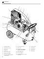
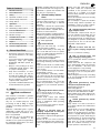
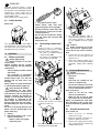
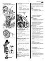
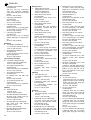
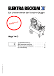
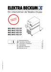
K0030IVZ.fm
O
OF
F
AU
TO
Mega 600 D
115 167 7696 / 3003 - 1.1
Betriebsanleitung . . . . . . . . . . . . . . . . . . . . 3
Operating Instruction . . . . . . . . . . . . . . . . 10
Instructions d'utilisation . . . . . . . . . . . . . . 16
Handleiding . . . . . . . . . . . . . . . . . . . . . . . 23
Manuale d’istruzioni . . . . . . . . . . . . . . . . . 30
Manual de uso . . . . . . . . . . . . . . . . . . . . . 37
Betjeningsvejledning . . . . . . . . . . . . . . . . 44
Bruksanvisning . . . . . . . . . . . . . . . . . . . . 50
Käyttökäsikirja . . . . . . . . . . . . . . . . . . . . . 57
U2K0030.fm
D DEUTSCH
ENG ENGLISH
KONFORMITÄTSERKLÄRUNG
Wir erklären in alleiniger Verantwortlichkeit, dass dieses Produkt mit
den folgenden Normen übereinstimmt* gemäß den Bestimmungen der
Richtlinien**
DECLARATION OF CONFORMITY
We herewith declare in our sole repsonsibility that this product complies
with the following standards*
in accordance with the regulations of the undermentioned
F FRANÇAIS
NL NEDERLANDS
DECLARATION DE CONFORMITE
Nous déclarons, sous notre seule responsabilité, que ce produit est en
conformité avec les normes ou documents normatifs suivants* en vertu
des dispositions des directives **
CONFORMITEITSVERKLARING
Wij verklaren als enige verantwoordelijke, dat dit product in
overeenstemming is met de volgende normen*
conform de bepalingen van de richtlijnen**
IT ITALIANO
ES ESPAÑOL
DICHIARAZIONE DI CONFORMITÀ
Noi dichiariamo sotto la nostra esclusiva responsabilità che il presente
prodotto è conforme alle seguenti norme* in conformità con le
disposizioni delle normative **
DECLARACION DE CONFORMIDAD
Declaramos bajo nuestra exclusiva responsabilidad, que el presente
producto cumple con las siguientes normas* de acuerdo a lo dispuesto
en las directrices** Homologación de
PT PORTUGUÊS
SV SVENSKA
DECLARAÇÃO DE CONFORMIDADE
Declaramos sob nossa responsabilidade que este produto está de
acordo com as seguintes normas* de acordo com as directrizes dos
regulamentos **
FÖRSÄKRAN OM ÖVERENSSTÄMMELSE
FIN SUOMI
NO NORGE
VAATIMUKSENMUKAISUUSVAKUUTUS
Vakuutamme, että tämä tuote vastaa seuraavia normeja* on direktiivien
määräysten mukainen**
SAMSVARSERKLÆRING
Vi erklærer under eget ansvar at dette produkt samsvarer med følgende
normer* henhold til bestemmelsene i direktiv**
DA DANSK
POL POLSKI
OVERENSSTEMMELSESATTEST
Hermed erklærer vi på eget ansvar, at dette produkt stemmer overens
ed følgende standarder* iht bestemmelserne i direktiverne**
OŚWIADCZENIE O ZGODNOŚCI
Oświadczamy z pełną odpowiedzialnością, że niniejszy produkt
odpowiada wymogom następujących norm* według ustaleń wytycznych
**
EL ΕΛΛHNIKA
HU MAGYAR
∆ΗΛΩΣΗ ΑΝΤΙΣΤΟΙΧΕΙΑΣ
∆ηλώνουµε µε ιδία ευθύνη ότι το προϊόν αυτό αντιστοιχεί στις
ακόλουθες προδιαγραφές*
σύµφωνα µε τις διατάξεις των οδηγιών**
MEGEGYEZŐSÉGI NYILATKOZAT
Kizárólagos felelősségünk tudatában ezennel igazoljuk, hogy ez a
termék kielégíti az alábbi szabványokban lefektetett követelményeket*
megfelel az alábbi irányelvek előírásainak**
Vi försäkrar på eget ansvar att denna produkt överensstämmer med
följande standarder* enligt bestämmelserna i direktiven**
MEGA 600 D
* EN 60204-1, EN 60335-1, EN 1012-1
** 98/37/EG - 93/ 68/EWG - 89/336/EWG - 73/23/EWG - 87/404/EWG
Jürgen Kusserow
Vorstand
ELEKTRA BECKUM AG – Daimlerstraße 1 – 49716 Meppen
1001013/ 01
2
Xk0016e.fm
Operating Instruction
ENGLISH
ENGLISH
1. Machine Overview
2
3
4
1
5
6
17
O
F
OF
AU
TO
7
16
15
14
8
12
11
9
13
10
1
Compressor pump
8
Hose reel with air hose
14
Pressure vessel
2
Air intake filter housing
9
Power cable
15
Oil drain plug
3
On/Off switch
10
16
Oil sight glass
4
Safety valve
Air outlet for non-regulated,
unfiltered compressed air
17
Oil filler plug
11
Filter/Regulator unit
12
Pressure regulator
13
Condensate drain cock of pressure vessel
5
Tank pressure gauge
6
Outlet pressure gauge
7
Air outlet for regulated, filtered
compressed air
10
ENGLISH
1.
Machine Overview .................... 10
2.
Please Read First!..................... 11
Children, juveniles and persons not having been instructed in its usage are not
permitted to operate this machine and
any air tools connected to it.
3.
Safety ......................................... 11
3.2
Table of Contents
3.1 Specified conditions of use ......... 11
3.2 General safety instructions ......... 11
3.3 Safety devices ............................ 12
4.
Operation................................... 12
4.1 Mains connection........................ 12
4.2 Generating compressed air ........ 12
5.
Care and Maintenance.............. 12
5.1 Periodic maintenance ................. 12
5.2 Machine storage ......................... 13
6.
Available Accessories......... 13/64
7.
Trouble Shooting ...................... 15
8.
Repairs....................................... 15
9.
Environmetal protection .......... 15
10. Technical Specifications.......... 15
2. Please Read First!
•
Read these instructions before use.
Pay special attention to the safety
instructions.
•
If you notice transport damage while
unpacking, notify your supplier
immediately. Do not operate the
machine!
•
Dispose of the packing in an environmentally friendly manner. Take
to a proper collecting point.
•
Keep these instructions for reference on any issues you may be
uncertain about. When the compressor is used commercially, also keep
the test certificates of the individual
compressed air components.
•
If you lend or sell this machine be sure
to have the instructions go with it.
3. Safety
3.1
Specified conditions of
use
This machine is intended to generate
compressed air required for the operation of air tools.
Any use for medical purposes, food
processing as well as filling of oxygen
cylinders for breathing equipment is not
permitted.
Explosive, combustible gases or gases
detrimental to health may not be compressed. Operation in hazardous locations is not permitted.
Any other use is not as specified. Use
not as specified, alteration of the
machine or use of parts not approved by
the equipment manufacturer, can cause
unforeseeable damage!
General safety instructions
When using this electric tool observe the
following safety instructions, to exclude
the risk of personal injury or material
damage.
Please also observe the special safety
instructions in the respective chapters;
Keep all documents, supplied with the
machine, for future reference.
Observe the statuary accident insurance
institution regulations and regulations for
the prevention of accidents pertaining to
the operation of air compressors and air
tools, where applicable.
A
General Hazard!
Keep your work area tidy – a messy
work area invites accidents.
Be alert. Know what you are doing. Set
out to work with reason. Do not operate
electric tool while under the influence of
drugs, alcohol or medication.
Consider environmental conditions.
Keep work area well lighted.
Prevent adverse body positions. Ensure
firm footing and keep your balance at all
times.
Make sure the electric tool stands safely
and can not topple over (check air pressure of tyres).
Do not operate electric tool near inflammable liquids or gases.
Keep bystanders, particularly children,
out of the work area. Do not permit other
persons to touch the tool or power cable
while the electric tool is running.
Do not overload electric tool – use it only
within the performance range it was
designed for (see Technical Specifications).
B
Danger! Risk of electric shock!
Do not expose electric tool to rain.
Do not operate electric tool in damp or
wet environment.
Prevent body contact with earthed
objects such as radiators, pipes, cooking
stoves or refrigerators when operating
this electric tool.
Do not use the power cable for any purpose it is not intended for.
A
Risk of personal injury by
escaping compressed air and parts
hurled about by escaping air!
Never direct compressed air against persons or animals!
Ensure all air tools and accessories
used are designed for the working pressure or are supplied via a pressure regulator.
Please note that, when disconnecting
the quick coupler, the compressed air
contained in the pressure hose will
escape all of a sudden. You should
therefore firmly hold the air hose when
disconnecting it.
Ensure all screwed connections are fully
tightened at all times.
Do not attempt to repair the machine
yourself! Only trained specialists are
permitted to service or repair compressors, pressure vessels and air tools.
generated by lubricated
A Hazard
compressed air!
Use lubricated compressed air only for
air tools requiring such supply. Do not
use an air hose, used to supply lubricated compressed air, to supply air tools
not designed for operation on lubricated
compressed air. Do not fill tires with
lubricated compressed air.
A
Risk of burns from the surfaces of parts carrying compressed
air!
Let tool cool off before servicing.
of personal injury and
A Risk
crushing by moving parts!
Do not operate the electric tool without
installed guards.
Please note that the compressor will
start automatically when the pressure
falls off to minimum! – disconnect from
power supply prior to any servicing.
Ensure that when switching on (e.g. after
servicing) no tools or loose parts are in
the electric tool.
When coiling the air hose up or uncoiling
it, do not reach between the crank and
the transport handle.
A
Hazard generated by insufficient personal protection gear!
Wear hearing protection.
Wear safety glasses.
Wear mask respirator when work generates dust or mist detrimental to health.
Wear suitable work clothes. When working outdoors wearing of non-slip shoes is
recommended.
generated by electric
A Hazard
tool defects!
Keep electric tool and accessories in
good repair. Observe the maintenance
instructions.
Check electric tool for possible damage
before any use: Before operating the
electric tool all safety devices, protection
devices or slightly damaged parts must
be inspected for proper functioning as
specified. Check to see that all moving
parts work properly and do not jam. All
parts must be correctly installed and
meet all conditions necessary for the
proper operation of the electric tool.
11
ENGLISH
Damaged protection devices or parts
must be repaired or replaced by a qualified specialist. Have damaged switches
replaced by a service centre. Do not
operate electric tool if the switch can not
be turned ON or OFF.
Keep handles free of oil and grease.
3.3
23
24
25
19
Safety devices
3.
Safety valve
Plug power cable in again.
Protect power cable from heat,
aggressive liquids and sharp edges.
F
O
OF
AU
Use only extension cables with sufficient lead cross section (see "Technical Specifications").
TO
Do not stop the machine by unplugging, but switch OFF using the ON/
OFF switch.
18
The spring-loaded safety valve (18) is
incorporated into the pressure switch.
The safety valve opens if the max. permissible pressure is exceeded.
Unplug after use.
4.2
1.
4. Operation
4.1
Mains connection
High Voltage
B Danger!
Operate machine in dry envi-
3.
Generating compressed
air
Connect air hose to compressor.
Depending on the purpose of application two outlets are available.
− Air outlet for regulated, filtered
compressed air (20).
− Air outlet for non-regulated, unfiltered compressed air (21).
.
20
A
Caution!
Before connecting an air tool,
make sure the max. operating pressure of the air tool used is not exceeded!
4.
Connect air tool to the compressor's
air hose. You are now ready to work
with the air tool.
5.
Switch the compressor OFF, if you
do not continue working immediately
afterwards. Unplug after switching
OFF.
ronment only.
Operate machine only on a power
source complying with the following
requirements:
−
outlets properly installed, earthed
and tested;
−
fuse protection in accordance
with the technical specifications.
5. Care and Maintenance
A Danger!
Prior to all servicing:
Position power cable so it does not
interfere with the work and is not
damaged.
Always check to see that the machine
is switched OFF before plugging in.
1.
Unplug.
2.
Interchange phases with a screwdriver as illustrated:
− Depress switch (19) slightly.
− and turn by 180 °.
Switch Off.
−
Unplug.
−
Wait until the compressor has
come to a complete stop.
−
Ensure the compressor and all air
tools and accessories connected
to it are relieved from pressure.
After all servicing:
2.
Start compressor (22) and wait until
the max. tank pressure is reached
(compressor shuts off).
22
F
O
OF
AU
TO
−
Check to see that all safety
devices are operational.
−
Make sure that no tools or other
parts remain on or in the machine.
Repair and maintenance work other
than described in this section must
only be carried out by qualified specialists.
5.1
Periodic maintenance
Prior to each use
• Check air hoses for
replace if necessary.
The tank pressure is indicated by
the tank pressure gauge (23).
12
−
21
direction of rotation!
B Check
Depending on the phase
sequence, the motor could turn in the
wrong direction. This can damage the
machine. Therefore the direction of
rotation is to be checked every time
the machine is connected to the
power supply: The pulley of the compressor pump must turn in the direction indicated by the arrow on the belt
guard.
If it turns in the wrong direction, two
phases must be interchanged in the
power cable plug:
Set pressure regulator (24) to
required working pressure. The current working pressure is indicated
by the regulated pressure gauge
(25).
damage,
•
Check all screwed connections for
tightness, tighten if necessary.
•
Check power supply cable for damage, if necessary have replaced by
a qualified electrician.
ENGLISH
Every 50 operating hours
• Check air filter element (26) of compressor pump, clean if necessary.
•
Drain condensate from filter/regulator unit (32).
•
Check V-belt:
− Remove belt guard (33).
− Retension V-belt or replace, if
necessary.
− To adjust the V-belt tension,
loosen the four screws at the
motor base and shift the motor.
− Tighten the screws at the motor
base again.
− Replace the belt guard.
26
•
33
Check oil level (27) of compressor
pump, top up if necessary (28).
27
O
OF
F
AU
TO
6. Available Accessories
For special applications the following
accessories are available at your specialist dealer – see back cover for illustrations:
Sealing
A Air Caulking Gun KP 910
for commercially available
tridges.
Stock-no. 090 101 0030
Sheet metal cutting
B Air Nibbler BN 540
extra small cutting radius; cuts steel
sheet up to 1.0 mm thickness.
Stock-no. 090 100 6784
Drilling
C Air Drill BM 310
especially handy tool for low-fatigue
working; right-hand rotation only.
Stock-no. 090 100 6725
•
29
•
28
Drain condensate from pressure
vessel (30).
Every 250 operating hours
• Replace air intake filter element of
compressor pump.
•
30
•
Clean air filter element (31) of filter/
regulator unit.
Replace air filter element of filter/
regulator unit.
Every 500 operating hours
• Drain oil from compressor pump
through the drain plug (29) and fill
with fresh oil.
A
Dispose of the waste oil environmentally safe by taking it to a
proper collecting point!
Every 1000 operating hours
• Have unit serviced by an authorized
service station. This will extent the
compressor's service life considerably.
5.2
Switch unit OFF and unplug.
2.
Release pressure from tank and all
connected air tools.
3.
Store machine in such way that it
cannot be started by unauthorized
persons.
A
31
32
Caution!
Do not store machine unprotected outdoors or in damp environment.
Do not lay machine on its side for
transportation or storing.
Air Drill BM 500 (not shown)
with 3/8" keyless chuck, fully reversible with quick reverse feature.
Stock-no. 090 105 4533
Stapling / nailing
D Combination Air Stapler/Nailer
Kombi 40/50
for staples (type 90) from 20 mm to
40 mm and finishing nails (type
SKN) from 20 mm to 50 mm.
Stock-no. 090 105 4720
•
Combination
Air
Stapler/Nailer
Kombi 32 (not illustrated)
for staples (type 90) from 15 mm to
32 mm and finishing nails (type
SKN) from 16 mm to 32 mm.
Stock-no. 090 105 4711
•
Air Stapler KG 80/16 (not illustrated)
for staples (type 80) from 6 mm to
16 mm.
Stock-no. 090 105 4681
•
Air Stapler KG 90/25 (not illustrated)
for staples (type 90) from 15 mm to
25 mm.
Stock-no. 090 105 4690
•
Air Stapler KG 90/40 (not illustrated)
for staples (type 90) from 20 mm to
40 mm.
Stock-no. 090 105 4703
•
Air Finish Nailer SKN 50
(not illustrated)
for finishing nails (type SKN) from
20 mm to 50 mm.
Stock-no. 090 105 4738
Machine storage
1.
car-
Spray painting
E
Spray Gun FB 2200 HVLP
High-volume low-pressure feature
reduces paint mist bounce-back
and provides thicker coating at less
paint consumption.
Stock-no. 090 105 4460
13
ENGLISH
•
Paint Spray Gun FB 2200
(not illustrated)
with 0.5 l flow cup; professional
spray gun; steplessly adjustable
round, horizontal and vertical spray
pattern.
Stock-no. 090 105 4452
•
Paint Spray Gun SB 200
(not illustrated)
with 1.0 l siphon cup.
Stock-no. 090 100 3882
•
Paint Spray Gun FB 150
(not illustrated)
with 0.5 l flow cup; for spraying primers and paints of varying viskosity.
Stock-no. 090 100 3874
•
Paint Spray Gun FB 90
(not illustrated)
with 0.75 l flow cup; for spraying
primers and paints of varying viskosity.
Stock-no. 090 105 6064
Chiselling
F
Air Hammer Set MHS 450
for construction and auto body work
Stock-no. 090 100 9210
•
Air Hammer Set MHS 315
(not illustrated)
to take off plaster and tiles and for
light chiselling work.
Stock-no. 090 100 6911
Tyre inflating / checking
G Tyre Inflator Gauge RF 480
professional version (calibrated).
Stock-no. 090 105 4630
•
•
•
Tyre Inflator Gauge RF 200
(not illustrated)
for inflating tyres and balls (calibrated).
Stock-no. 090 105 6188
Tyre Inflator Gauge RF 100
(not illustrated)
same as RF 200, but not calibrated.
Stock-no. 090 102 6724
Blow Gun BP 300 (not illustrated)
all plastic body; venturi nozzle provides extra high air volume.
Stock-no. 090 105 4614
•
Blow Gun BP 70 (not illustrated)
light metal body (with 100 mm
extension nozzle).
Stock-no. 090 102 6726
•
Blow Gun BP 60 (not illustrated)
light metal body (short).
Stock-no. 090 102 6718
14
•
Braided Air Hose (not illustrated)
c/w quick coupler and male plug;
length 10 m; outer diameter 15 mm;
inner diameter 9 mm.
Stock-no. 090 105 4924
•
Impact Wrench SR 340 Set
(not illustrated)
professional version; many accessories included.
Stock-no. 090 105 6137
•
Bulk Braided Air Hose
(not illustrated)
length 50 m; outer diameter 15 mm;
inner diameter 9 mm.
Stock-no. 090 105 4932
•
Impact Wrench SR 140 Set
(not illustrated)
for multiple DIY and automotive
applications; complete with many
accessories.
Stock-no. 090 100 8582
•
Self-storing Coil Air Hose, Rilsan
(not illustrated)
c/w quick coupler and male plug;
2.5 m working length; outer diameter 8 mm; inner diameter 6 mm.
Stock-no. 090 105 4940
•
Impact Wrench SR 120 Set
(not illustrated)
requires only minimal amount of air,
thus can be run on small compressors; complete with many accessories.
Stock-no. 090 100 6750
•
Self-storing Coil Air Hose, Rilsan
(not illustrated)
c/w quick coupler and male plug;
7.5 m working length; outer diameter 8 mm; inner diameter 6 mm.
Stock-no. 090 105 4959
•
•
Ratchet Wrench RS 320
(not illustrated)
due to narrow design and rubbercovered ratchet head it is well suited
for automotive applications and
work in confined areas.
Stock-no. 090 105 4541
Self-storing Coil Air Hose, Rilsan
(not illustrated)
c/w quick coupler and male plug;
10.0 m working length; outer diameter 10 mm; inner diameter 8 mm.
Stock-no. 090 105 4967
•
Hand-crank Hose Reel SA 100
(not illustrated)
c/w 20.0 m braided air hose; outer
diameter 15 mm; inner diameter
9 mm.
Stock-no. 090 105 4975
•
Automatic Retractable Hose Reel
SA 200 (not illustrated)
suitable for wall and ceiling mounting; retracts automatically by simply
pulling on hose; with 8 m PU air
hose; outer diameter 13 mm; inner
diameter 8 mm.
Stock-no. 090 105 4550
•
Ratchet Wrench RS 220 Set
(not illustrated)
this set comes complete with many
accessories.
Stock-no. 090 100 6717
•
Air Screwdriver DS 1610
(not illustrated)
reversible with quick
action.
Stock-no. 090 101 2440
Tyre Inflator Gauge RF 363
(not illustrated)
same as RF 480, but not calibrated.
Stock-no. 090 105 4622
Cleaning
H Blow Gun BP 200
all plastic body.
Stock-no. 090 105 4606
•
Driving screws
I
Impact Wrench SR 230
rugged impact wrench for DIY and
automotive applications.
Stock-no. 090 105 6170
reversing
Spraying
J
Spray Gun SPP 161
for spraying degreaser, oil, liquid
wax, etc.
Stock-no. 090 105 4525
•
Combination Spray Gun UBS 820
(not illustrated)
for commercially available 1.0 l
screw-top cartridges.
Stock-no. 090 105 4479
Accessory kits
L
Accessory Kit LPZ 7-S
comprising: Blow gun, tyre inflator
gauge, tyre valve nozzle, needle tip
nozzle, paint spray gun, spray gun,
self-storing coil air hose.
Stock-no. 090 100 3858
•
Accessory Kit LPZ 7-P
(not illustrated)
comprising: Blow gun, tyre inflator
gauge, tyre valve nozzle, needle tip
nozzle, paint spray gun, spray gun,
10 m braided air hose.
Stock-no. 090 100 3890
•
Accessory Kit LPZ 6 (not illustrated)
comprising: Blow gun, tyre inflator
gauge, tyre valve nozzle, needle tip
nozzle, paint spray gun, 5 m braided
air hose.
Stock-no. 090 104 4487
•
Accessory Kit LPZ 4 (not illustrated)
comprising: Blow gun, tyre inflator
gauge, paint spray gun, self-storing
Air hoses
K Hose Reel ST 200
swivels through 360°; with 30 m PU
air hose.
Stock-no. 090 105 4568
•
Braided Air Hose (not illustrated)
c/w quick coupler and male plug;
length 5 m; outer diameter 12 mm;
inner diameter 6 mm.
Stock-no. 090 105 4908
•
Braided Air Hose (not illustrated)
c/w quick coupler and male plug;
length 10 m; outer diameter 12 mm;
inner diameter 6 mm.
Stock-no. 090 105 4916
ENGLISH
coil air hose.
Stock-no. 090 101 3845
•
Accessory Kit LPZ 2 (not illustrated)
contains change handle with blow
gun, tyre inflator gauge, paint spray
gun, self-storing coil air hose.
Stock-no. 090 105 5971
•
•
7. Trouble Shooting
A Danger!
Prior to all servicing:
−
Switch Off.
−
Unplug.
−
Wait until the compressor has
come to a complete stop.
−
Ensure the compressor and all air
tools and accessories connected
to it are relieved from pressure.
•
Check to see that all safety
devices are operational.
−
Make sure that no tools or other
parts remain on or in the
machine.
Check valve leaky.
− Have check valve serviced by
qualified service centre.
Compressor does not run:
• No mains voltage.
− Check cables, plug, outlet and
mains fuse.
Hose connection between compressor and air tool leaky.
− Check air hoses, replace defective parts if necessary.
8. Repairs
A Danger!
Repairs to electric tools must
be carried out by qualified electricians only!
Motor has overheated, caused by
insufficient cooling (cooling fins covered).
− Remove cause for overheating
and allow to cool down for
approx. 10 minutes, then start
again.
−
•
•
Compressor was stopped by
unplugging.
− Switch compressor OFF at the
On/Off switch, then ON again.
Compressor runs but does not build
up sufficient pressure.
• Drain cock on cup of filter/regulator
unit open.
− Close drain cock.
After all servicing:
− Open pressure regulator more.
Mains voltage too low.
− Use only extension cables with
sufficient lead cross section (see
"Technical Specifications"). Avoid
using extension cable with cold
machine.
Electric tools in need of repair can be
send to the service centre in your country. See spare parts list for address.
Please attach a description of the fault to
the electric tool.
9. Environmetal protection
The machine's packaging can be 100 %
recycled.
Worn out machines and accessories
contain considerable amounts of valuable raw and plastic materials, which can
be recycled.
Air tool is not supplied with sufficient
pressure.
• Pressure regulator not opened wide
enough.
These instructions are printed on chlorine-free bleached paper.
10. Technical Specifications
Suction capacity
l/min
480
Free air delivery (volume flow rate)
l/min
330
Filling rate
l/min
370
bar
10
l
90
Working pressure (compression end pressure)
Pressure vessel volume
No. of air outlets
2
Compressor pump model
B 4900 B
No. of cylinders
Speed (compressor pump)
Motor capacity
2
min
-1
1275
kW
3.0
Supply voltage (50 Hz)
V
400
Rated current
A
6.2
Fuse protection min.
A
10 (time-lag)
Degree of protection
Max. overall cable length when using extension cables:
– at 3 x 1.0 mm2 lead cross section
– at 3 x 1.5 mm2 lead cross section
– at 3 x 2.5 mm2 lead cross section
IP 54
m
m
m
Oil grade (compressor pump)
Required oil quantity (compressor pump)
15
25
40
SAE 40
l
1.1
Dimensions length x width x height
cm
123 x 56 x 91
Weight
kg
98
Sound pressure level LPA at 4 m max.
dB (A)
73 ± 3
Sound power level LWA
dB (A)
93
15
A
090 101 0030
B
090 100 6784
C
090 100 6725
D
090 105 4720
E
090 105 4460
F
090 100 9210
G
090 105 4630
H
090 105 4606
I
090 105 6170
J
090 105 4525
K
090 105 4568
L
090 100 3858
www.elektra-beckum.de
ZINDEL - Technische Dokumentation und Multimedia, www.zindel.de
U3K0028_wf.fm