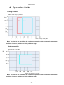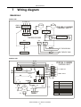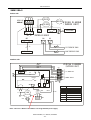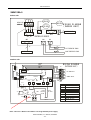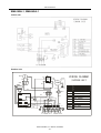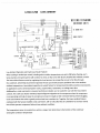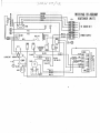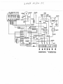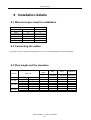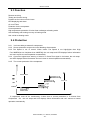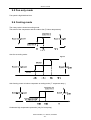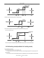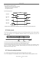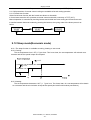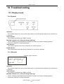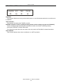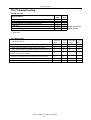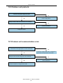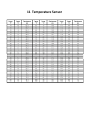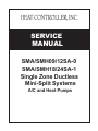
1
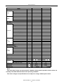
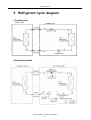
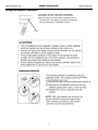
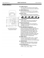
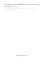
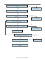
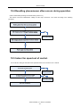
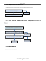
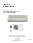
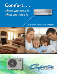
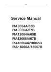
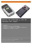
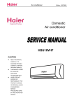
SERVICE
MANUALNeText
SMA/SMH09/12SA-0
SMA/SMH18/24SA-1
Single Zone Ductless
Mini-Split Systems
A/C and Heat Pumps
Contents
1
Precaution ....................................................................................................................4
1.1 Safety Precaution...................................................................................................................................4
1.2 Warning ..................................................................................................................................................4
2
3
4
5
6
7
8
Function .......................................................................................................................7
Dimension .................................................................................................................... 8
Specification ................................................................................................................10
Refrigerant cycle diagram......................................................................................... 14
Operation limits ......................................................................................................... 15
Wiring diagram........................................................................................................... 16
Installation details...................................................................................................... 23
8.1 Wrench torque sheet for installation .................................................................................................... 23
8.2 Connecting the cables ......................................................................................................................... 23
8.3 Pipe length and the elevation .............................................................................................................. 23
8.4 Air purging of the piping and indoor unit .............................................................................................. 24
8.5 Pumping down (Re-installation)........................................................................................................... 26
8.6 Re-air purging (Re-installation)............................................................................................................ 27
8.7 Balance refrigerant of the 2-way, 3-way valves ................................................................................... 28
8.8 Evacuation ........................................................................................................................................... 29
8.9 Gas charging........................................................................................................................................ 30
9
Electronic function .................................................................................................... 31
9.1 Electronic control working environment...............................................................................................31
9.2 Proper symbols and their meaning ...................................................................................................... 31
9.3 Function ............................................................................................................................................... 32
9.4 Protection ............................................................................................................................................. 32
9.5 Fan only mode ..................................................................................................................................... 33
9.6 Cooling mode ....................................................................................................................................... 33
9.7 Dehumidifying mode ............................................................................................................................ 34
9.8 Heating mode....................................................................................................................................... 34
9.9 Defrosting mode(available for heating mode) ..................................................................................... 35
9.10 Auto mode .......................................................................................................................................... 36
9.11 Force cooling function ........................................................................................................................ 36
9.12 Sleep mode(Economic mode) ........................................................................................................... 37
9.13 Auto restart function ........................................................................................................................... 38
9.14 Turbo mode ........................................................................................................................................ 38
10
Troubleshooting......................................................................................................... 39
10.1 Display board ..................................................................................................................................... 39
10.2 Troubleshooting.................................................................................................................................. 41
10.3 Diagnostic chart.................................................................................................................................. 42
10.4 Resetting phenomenon often occurs during operation...................................................................... 44
10.5 Indoor fan speed out of control . ........................................................................................................ 44
10.6 Temperature sensor error................................................................................................................... 45
Heat Controller, Inc. Jackson, MI 49203
-2-
Content
10.7 Over current protection of the compressor occurs 4 times................................................................ 45
10.8 EEROM error...................................................................................................................................... 45
10.9 Outdoor unit protects.......................................................................................................................... 46
10.10 Indoor unit communication error. ..................................................................................................... 46
11
Characteristic of temperature sensor ...................................................................... 47
Heat Controller, Inc. Jackson, MI 49203
-3-
Service manual
1 Precaution
1.1 Safety Precaution
To prevent injury to the user, other people, or property damage, the following
instructions must be followed.
Incorrect operation due to ignoring instruction will cause harm or damage.
Before servicing unit, be sure to read this service manual.
1.2 Warning
Installation
Do not use a defective or underrated circuit breaker. Use this appliance on a dedicated
circuit.
There is risk of fire or electric shock.
For electrical work, contact the dealer, seller, a qualified electrician, or an Authorized
service center.
Service by unqualified individuals may damage product and there is risk of fire or electric shock.
Always ground the product.
There is risk of fire or electric shock.
Install the panel and the cover of control box securely.
There is risk of fire of electric shock.
Always install a dedicated circuit and breaker.
Improper wiring or installation may cause fire or electric shock.
Use the correctly rated breaker of fuse.
There is risk of fire or electric shock.
Do not modify or extend any power cable.
There is risk of fire or electric shock.
Do not install, remove, or reinstall the unit by yourself (customer).
There is risk of fire, electric shock, explosion, or injury.
Be caution when unpacking and installing the product.
Sharp edges could cause injury, be especially careful of the case edges and the fins on the condenser and
evaporator coils.
For installation, always contact the dealer or an Authorized service center.
There is risk of fire, electric shock, explosion, or injury.
Do not install the product on a defective or inadequate installation stand.
It may cause injury, accident, or damage to the product.
Be sure the installation area does not deteriorate with age.
If the base collapses, the air conditioner could fall with it, causing property damage, product failure, and personal
injury.
Do not let the air conditioner run for a long time when the humidity is very high and a
door or window is left open.
Moisture may condense and wet or damage furniture.
Take care to ensure that power cable could not be pulled out or damaged.
Install per local and national codes.
Heat Controller, Inc. Jackson, MI 49203
-4-
Service manual
Do not place anything on the power cable.
There is risk of fire or electric shock.
Do not touch or operate the product with wet hands.
There is risk of fire or electric shock.
Do not allow water to run into electric parts.
It may cause fire, failure of the product, or electric shock.
Do not store or use flammable gas or combustible near the product.
There is risk of fire or failure of product.
Do not use the product in a tightly closed space for a long time.
Oxygen deficiency could occur.
When flammable gas leaks, turn off the gas and open a window for ventilation before
turning the product on.
Do not use the telephone or turn switches on or off.
There is risk of explosion or fire.
In the event of strange sounds, or smell or smoke comes from product, turn the breaker off.
There is risk of electric shock or fire.
Stop operation and close the window in storm or hurricane.
There is risk of property damage, failure of product, or electric shock.
Do not open the inlet grill of the product during operation. (Do not touch the electrostatic
filter, if the unit is so equipped.
There is risk of physical injury, electric shock, or product failure.
When the product is soaked (flooded or submerged), contact an Authorized service
center.
There is risk of fire or electric shock.
Be cautious that water cannot enter the product.
There is risk of fire, electric shock, or product damage.
Ventilate the product from time to time when operating it together with a stove, etc.
There is risk of fire or electric shock.
Turn the main power off when cleaning or maintaining the product.
There is risk of electric shock.
When the product is not be used for a long time, disconnect the power supply by turning
off the breaker.
There is risk of product damage or failure, or unintended operation.
Take care to ensure that nobody could step on or fall onto the outdoor unit.
This could result in personal injury and product damage.
CAUTION
Always check for gas (refrigerant) leakage after installation or repair of product.
Low refrigerant levels may cause failure of product.
Install the drain hose to ensure that water is drained away properly.
A bad connection may cause water leakage.
Keep units level.
To avoid vibration of water leakage.
Do not install the product where the noise or hot air from the outdoor unit could offend or
otherwise affect neighbors.
Heat Controller, Inc. Jackson, MI 49203
-5-
Service manual
the neighborhoods.
It may cause a problem for your neighbors.
Use two or more people to lift and transport the product.
Avoid personal injury.
Do not install the product where it will be exposed to sea wind (salt spray) directly.
It may cause corrosion on the product. Corrosion, particularly on the condenser and evaporator fins, could cause
product malfunction or inefficient operation.
Operational
Do not expose the skin directly to cool air for long periods of time. (Do not sit in the
draft).
This could harm to your health.
Do not use the product for special purposes, such as preserving foods, works of art, etc.
It is a consumer air conditioner, not a precision cooling/heating system.
There is risk of damage or loss of property.
Do not block the inlet or outlet of air flow.
It may cause product failure.
Use a soft cloth to clean. Do not use harsh detergents, solvents, etc.
There is risk of fire, electric shock, or damage to the plastic parts of the product.
Do not touch the metal parts of the product when removing the air filter. They are very
sharp.
There is risk of personal injury.
Do not step on or put anything on the product. (outdoor units)
There is risk of personal injury and failure of product.
Always insert the filter securely. Clean the filter every two weeks or more often if
necessary.
A dirty filter reduces the efficiency of the air conditioner and could cause product malfunction or damage.
Do not insert hands or other object through air inlet or outlet while the product is
operated.
There are sharp and moving parts that could cause personal injury.
Do not drink the water drained from the product.
It is not sanitary could cause serious health issues.
Use a firm stool or ladder when cleaning or maintaining the product.
Be careful and avoid personal injury.
Replace the all batteries in the remote control with new ones of the same type. Do not
mix old and new batteries or different types of batteries.
There is risk of fire or explosion.
Do not recharge or disassemble the batteries. Do not dispose of batteries in a fire.
They may burn of explode.
If the liquid from the batteries gets onto your skin or clothes, wash it well with clean
water. Do not use the remote if the batteries have leaked.
The chemical in batteries could cause burns or other health hazards.
Heat Controller, Inc. Jackson, MI 49203
-6-
Service manual
2 Function
Indoor unit
20. Turbo(for 9K and 12K)
1.
Operation ON/OFF by remote
controller
2. Sensing by room temperature
This function enables the unit to reach the preset
temperature in the shortest time under cooling mode.
Outdoor unit
Room temperature sensor. Pipe temperature
1. Power relay control
sensor.
3. Room temperature control
Maintain the room temperature in accordance with
The unit has 3 mins delay between continuously
ON/OFF operations.
2. Low noise air flow system
the setting temperature.
4. Starting temperature control
Indoor fan is delayed for 5 sec at the starting.
5. Time Delay Safety control
Bird tail propeller fan makes the outdoor unit run
more quietly
3. Hydrophilic aluminum fin
Restarting is for approx. 3 minutes.
The hydrophilic fin can improve the heating
6. Indoor fan speed control
efficiency at operation mode.
High, med, low, breeze.
4. 4 way valve control
7. Operation indication Lamps (LED)
Light up in the LED for each operation mode.
8. Two-direction air vane
It is only operated in the heating operation mode
except defrosting operation.
5.
The unit will decide the louver direction according
to operation mode.
Anti-rust cabinet
Made from electrolytic zinc steel sheet and anti-rust
coated components.
9. Sleep mode auto control
6. Valve protection cover
The fan is turn to low speed (cooling/heating).
The unit will be turn off after seven hours.
It protects the valves and prevents water from
dripping.
10. Independent dehumidification
The function is usually used in rainy days in
springtime or damp areas
11. Self-diag. function
The function will be operate in any operation mode.
12.
Air flow Direction control
The louver can be set at the desired position or
swing up and down automatically
13.
Auto mode
The unit can be change by the room temperature.
14.
Anti-cold function
Prevent the cold wind at the beginning of unit start.
15.
16.
17.
18.
19.
Temp. Compensation
Defrost mode
Auto-restart function
Flexible wiring connection
Easy clean panel
Heat Controller, Inc. Jackson, MI 49203
-7-
Service manual
3 Dimension
Indoor unit
Dimension
W
H
D
9K
32.1
11.0
7.7
12K
35.7
11.3
9.3
18K
49.2
12.8
9.1
24K
49.2
12.8
9.1
Mode
Heat Controller, Inc. Jackson, MI 49203
-8-
Service manual
outdoor unit
Dimension
W
H
D
L1
L2
9K
30.7
21.3
9.8
21.6
10.5
12K
29.9
23.2
11.2
20.9
11.4
18K
24K
33.3
35.2
27.4
33.9
13.2
13.0
22.0
23.2
13.2
13.1
Mode
Heat Controller, Inc. Jackson, MI 49203
-9-
Service manual
4 Specification
Model
Ph-V-Hz
Btu/h
W
A
Btu/w.h
Btu/h
W
A
W/W
A
A
Power supply
Cooling
Heating
Capacity
Input
Rated current
SEER
Capacity
Input
Rated current
HSPF
Max. current
Starting current
Model
Type
Brand
Capacity
Input
Compressor Rated current(RLA)
Locked rotor Amp(LRA)
Thermal protector
Capacitor
Refrigerant oil
Model
Brand
Indoor
Input
fan motor
Capacitor
Speed(hi/mi/lo)
Btu/h
W
A
A
uF
ml
W
uF
r/min
CFM
dB(A)
Indoor air flow (Hi/Mi/Lo)
Indoor noise level (Hi/Mi/Lo)
Model
Brand
Outdoor
Input
fan motor
Capacitor
Speed
Outdoor air flow
Outdoor noise level
Refrigerant type R410A
Design pressure
Liquid side/ Gas side
Refrigerant Max. refrigerant pipe length
piping
Max. difference in level
Operation temp
Ambient temp
Application area
W
uF
r/min
CFM
dB(A)
oz
psig
in
ft
ft
ºF
ºF
ft
2
SMA09SA-0
SMH09SA-0
1, 115V~, 60Hz
9000
780
7
13
1, 115V~, 60Hz
9000
900
8.3
13
/
/
/
/
10000
900
8.3
7.7
11
10.2
/
40
EA82X1C-1FZDU1
ROTARY
TOSHIBA
8138
810
7.5
47
B350-135-141E
EA82X1C-1FZDU1
ROTARY
TOSHIBA
8138
810
7.5
40
B350-135-141E
45µF /250VAC
45μF /250VAC
350
WZDK20-38D
WELLING
25
350
WZDK20-38D
WELLING
25
/
——
1250/1000/800
1250/1000/800
400/325/250
41/35/28
YDK23-6A
BROAD OCEAN
75
6.5uF/260V
900
400/325/250
41/35/28
YDK23-6A
BROAD OCEAN
75
6.5uF/260V
900
1060
1060
53
53
37.0
37.7
650
Ф1/4 /Ф3/8
33
16
63-86
33
16
63-86
65-113
19-113
150-225
650
Ф1/4 /Ф3/8
150-225
Note:
The noise date is base on semi-anechoic chamber, during actual operation; these values are
normally somewhat different than actual operating conditions.
The above design and specifications are subject to change without prior notice.
Heat Controller, Inc. Jackson, MI 49203
- 10 -
Service manual
Model
Power supply
Cooling
Heating
Ph-V-Hz
Btu/h
W
A
Btu/w.h
Btu/h
W
A
W/W
A
A
Capacity
Input
Rated current
SEER
Capacity
Input
Rated current
COP
Max. current
Starting current
Model
Type
Brand
Capacity
Input
Compressor
Rated current(RLA)
Locked rotor Amp(LRA)
Thermal protector
Capacitor
Refrigerant oil
Model
Brand
Indoor
Input
fan motor
Capacitor
Speed(hi/mi/lo)
Indoor air flow (Hi/Mi/Lo)
Indoor noise level (Hi/Mi/Lo)
Outdoor
fan motor
Btu/h
W
A
A
uF
ml
W
uF
r/min
CFM
dB(A)
Model
Brand
Input
Capacitor
Speed
W
uF
r/min
Outdoor air flow
Outdoor noise level
Refrigerant type R410A
Design pressure
Refrigerant
piping
Operation temp
Ambient temp
Application area
Liquid side/ Gas side
Max. refrigerant pipe length
Max. difference in level
CFM
dB(A)
oz
PSIG
in
ft
ft
ºF
ºF℃
ft2
SMA12SA-0
1, 115V~, 60Hz
12000
1090
10
13
——
——
——
——
12.6
47
EA108X1C-1FZDU1
ROTARY
TOSHIBA
10918
1085
9.9
47
B440-135-141E
45μF /250VAC
350
WZDK25-38D
WELLING
32
——
1270/1100/1000
440/365/325
45/41/38
YDK23-6A
BROAD OCEAN
75
6.5uF/260V
900
1090
55
46.9
650
Ф1/4 /Ф1/2
33
16
63-86
65-113
195-280
SMH12SA-0
1, 115V~, 60Hz
12000
1090
10
13
13000
1160
10.6
7.7
14
47
EA108X1C-1FZDU1
ROTARY
TOSHIBA
10918
1085
9.9
47
B440-135-141E
45μF /250VAC
350
WZDK25-38D
WELLING
32
——
1270/1100/1000
440/365/325
45/41/38
YDK23-6A
BROAD OCEAN
75
6.5uF/260V
900
1090
55
47.6
650
Ф1/4 /Ф1/2
33
16
63-86
19-113
195-280
Note:
The noise date is base on semi-anechoic chamber, during actual operation; these values are
normally somewhat different than actual operating condition.
The above design and specifications are subject to change without prior notice.
Heat Controller, Inc. Jackson, MI 49203
- 11 -
Service manual
Model
Power supply
Cooling
Heating
Ph-V-Hz
Btu/h
W
A
Btu/w.h
Btu/h
W
A
W/W
A
A
Capacity
Input
Rated current
SEER
Capacity
Input
Rated current
HSPF
Max. current
Starting current
Model
Type
Brand
Capacity
Input
Compressor
Rated current(RLA)
Locked rotor Amp(LRA)
Thermal protector
Capacitor
Refrigerant oil
Model
Brand
Indoor
Input
fan motor
Capacitor
Speed(hi/mi/lo)
Indoor air flow (Hi/Mi/Lo)
Indoor noise level (Hi/Mi/Lo)
Outdoor
fan motor
Btu/h
W
A
A
uF
ml
W
uF
r/min
CFM
dB(A)
Model
Brand
Input
Capacitor
Speed
W
uF
r/min
Outdoor air flow
Outdoor noise level
Refrigerant type R410A
Design pressure
Refrigerant
piping
Operation temp
Ambient temp
Application area
Liquid side/ Gas side
Max. refrigerant pipe length
Max. difference in level
SMA18SA-1
1, 208/230V~, 60Hz
18000
1560
6.8
13
——
——
——
——
9.2
32.6
PA150X2CS-3KUU
ROTARY
TOSHIBA
15166/15354
1505/1510
7.30/6.65
32.6
UP3RE0391-T39
40μF /370VAC
750
YDK31-6B
WELLING
55
3
1070/1000/960
620/540/490
45/43/41
YDK53-6KB
WELLING
165
3uF/450V
840
CFM
dB(A)
oz
PSIG
in
ft
ft
℃ºF
℃ºF
ft2
1475
59
70.6
650
Ф1/4/Ф1/2
33
16
63-86
65-113
325-430
SMH18SA-1
1, 208/230V~, 60Hz
18000
1530
6.7
13
18000
1630
7.1
7.7
10.2
32.6
PA150X2CS-3KUU
ROTARY
TOSHIBA
15166/15354
1505/1510
7.30/6.65
32.6
UP3RE0391-T39
40μF /370VAC
750
YDK31-6B
WELLING
55
3
1070/1000/960
620/540/490
45/43/41
YDK53-6KB
WELLING
165
3uF/450V
840
1475
59
72.0
650
Ф1/4/Ф1/2
33
16
63-86
19-113
325-430
Note:
The noise date is base on semi-anechoic chamber, during actual operation; these values are
normally somewhat different than actual operation.
The above design and specifications are subject to change without prior notice.
Heat Controller, Inc. Jackson, MI 49203
- 12 -
Service manual
W
uF
r/min
SMA24SA-1
1, 208/230V~, 60Hz
24000
2000
8.8
13
——
——
——
——
14
34.8 A
PA200X2CS-3MUU
ROTARY
TOSHIBA
19820/20130
2000/1980W
9.70/8.75A
34.8 A
UP3SE0396-T39
50
750
YDK50-4B
WELLING
82/69/58
3
1260/1100/990
680/600/550
47/44/42
YDK100-6EB
WELLING
160
4
740
CFM
dB(A)
oz
PSIG
in
ft
ft
1475
59
84.7
650
Ф3/8/Ф5/8
33
16
Model
Ph-V-Hz
Btu/h
W
A
Btu/w.h
Btu/h
W
A
W/W
A
A
Power supply
Cooling
Heating
Capacity
Input
Rated current
SEER
Capacity
Input
Rated current
HSPF
Max. current
Starting current
Compressor
Indoor
fan motor
Model
Type
Brand
Capacity
Input
Rated current(RLA)
Locked rotor Amp(LRA)
Thermal protector
Capacitor
Refrigerant oil
Model
Brand
Input
Capacitor
Speed(hi/mi/lo)
Btu/h
W
A
A
uF
ml
W
uF
r/min
CFM
dB(A)
Indoor air flow (Hi/Mi/Lo)
Indoor noise level (Hi/Mi/Lo)
Model
Brand
Outdoor
Input
fan motor
Capacitor
Speed
Outdoor air flow
Outdoor noise level
Refrigerant type R410A
Design pressure
Liquid side/ Gas side
Refrigerant
Max. refrigerant pipe length
piping
Max. difference in level
Operation temp
Ambient temp
Application area
SMH24SA-1
1, 208/230V~, 60Hz
24000
2000
8.8
13
24000
2000
8.8
7.7
14
34.8 A
PA200X2CS-3MUU
ROTARY
TOSHIBA
19820/20130
2000/1980W
9.70/8.75A
34.8 A
UP3SE0396-T39
50
750
YDK50-4B
WELLING
82/69/58
3
1260/1100/990
680/600/550
47/44/42
YDK100-6EB
WELLING
160
4
740
1475
59
86.4
650
Ф3/8/Ф5/8
33
16
℃ºF
63-86
63-86
℃ºF
65-113
19-113
ft
2
430-605
430-605
Note:
The noise date is base on semi-anechoic chamber, during actual operation; these values are
normally somewhat different than actual operating condition.
The above design and specifications are subject to change without prior notice.
Heat Controller, Inc. Jackson, MI 49203
- 13 -
Service manual
5 Refrigerant cycle diagram
Cooling only
indoor unit
outdoor uni
Heat pump mode
Heat Controller, Inc. Jackson, MI 49203
- 14 -
Heat Controller, Inc.
Remote Controller
Owner’s Manual
Using the Remote Controller
Use the remote controller within a distance of 26' 3"
(8 meters) from the appliance, pointing it towards the
receiver. Reception is confirmed by a beep.
receiver
housing
Remove the battery cover by pressing and sliding it off.
2
Heat Controller, Inc.
Owner’s Manual
Remote Controller
Function Buttons
AUTO
COOL
*NOTE: Heat pump models only
ION and FOLLOW buttons
are optional functions.
4
DRY
HEAT*
FAN
Owner’s Manual
Remote Controller
Heat Controller, Inc.
Function Buttons (continued)
ECONOMY Button (Sleep Mode)
to maintain the most comfortable temperature
TIMER OFF Button
ION and FOLLOW buttons
are optional functions.
Press this recessed button to lock all current settings. Use the LOCK mode when you want to
prevent settings from being changed accidentally.
Press the LOCK button again to cancel the LOCK
function. A key symbol will appear on the remote
controller display when the lock function is activated.
5
Heat Controller, Inc.
Remote Controller
Indicators on LCD Display
The temperature setting (from 62°F (17°C)
to 88°F (30°C)) or timer setting (0~24h)
will be displayed. If FAN mode is selected,
there will be no display.
A key symbol is displayed when pushing
the LOCK button. Push the LOCK button
to clear display.
6
Owner’s Manual
Service manual
6 Operation limits
Cooling operation
Outdoor unit air temp ºC (ºF) DBT
N(113)
(104)
(95)
(86)
(77)
(68)
(41)
(50)
(59)
(68)
(77)
(86)
(95)
(104)
Indoor air temp. ºC (ºF) DBT
Note: The chart is the result from the continuous operation under constant air temperature
conditions. However, excludes the initial pull-down stage.
Heating operation
Indoor air temp ºC (ºF) DBT
N
(95)
(86)
(77)
(68)
(59)
-10
(14)
(23)
(41)
(59)
(77)
Outdoor unit air temp ºC (ºF) DBT
Note: The chart is the result from the continuous operation under constant air temperature
conditions. However, excludes the initial pull-down stage.
Heat Controller, Inc. Jackson, MI 49203
- 15 -
Service manual
7
Wiring diagram
SMA09SA-0
Indoor unit:
TO O UTDOOR U NIT
STEP MOTOR
1
2
3
4
OUTDOOR UNIT
INDOOR U NIT
5
INDOOR MOTOR
5
CN 3
CN6
JXZ_G1
ANION GENERATOR
CN8(9)
CONTROLLER BOARD
CN5
WIRING DIAGRAM
(INDOOR UNIT)
Y/G
ON SOME MODELS
G
CN 2
CN1
10
PI PE TEMPERATURE SENSOR
ROOM TEMPERATURE SENSOR
DISPLAY BOARD
outdoor unit:
XT1
P2
G
Y/G
3 4
WHITE
BLACK
RELA Y
RE D
CN3
CT1
N
L
CN9
R
1
2
WH ITE
WH ITE
RED
RED
WHITE
1
CA P1
CN4
FAN2
M
COMP
S
G BL UE
Y/G
BLACK
C
P OWER SUPP LY
G
N
CN10
Y/G
TO INDOOR UNIT
L N
G
Y/G
(OUTDOOR UNIT)
1 2
P1
CN2
WIRING DIAGRAM
BROW N
BLUE
BLAC K
RED
2
CAP2
Heat Controller, Inc. Jackson, MI 49203
- 16 -
CODE
COMP
PAR T NAME
COMPRE SSOR
CAP1
FAN2
CAP2
XTI
COMPRE SSOR CAP ACITOR
OUTDOO R FAN
OUTDOO R FAN CA PACITOR
7-WAY TERMINAL
CT1
RELAY
CURREN T INDUCT OR
COMPRE SSOR REL AY
Service manual
SMH09SA-0
Indoor unit:
TO O UTDOOR U NIT
STEP MOTOR
1
2
3
4
OUTDOOR UNIT
INDOOR U NIT
5
INDOOR MOTOR
5
CN 3
WIRING DIAGRAM
(INDOOR UNIT)
CN6
JXZ_G1
CONTROLLER BOARD
CN5
ANION GENERATOR
CN8(9)
Y/G
ON SOME MODELS
G
CN 2
CN1
10
PI PE TEMPERATURE SENSOR
ROOM TEMPERATURE SENSOR
DISPLAY BOARD
outdoor unit:
R
O
T
A
S
NR
E
O
D
S
N
ON
E
CS
WIRING DIAGRAM
BROWN
BLU E
BLA CK
RED
CN2
G
G
XT 1
P2
P1
(OUTDOOR UNIT)
TO INDOOR UN IT
Y/G
CN1
Y/G
R EL AY
FS1
C N3
RE D
CN6
CN5
L
N
CN4
N
CT 1
FS2
WHIT E
BLAC K
CN10
Y/G
G
COMP
S
BLUE
CAP1
R
M
WHI TE
RED
CA P2
F AN2
Y/G
G
CO DE
CO MP
CA P1
C
BLACK
POWER SUPPLY
FA N2
PART NAME
COMPRES SOR
COMPRES SOR CA PACITO R
CA P2
XT I
OUTDOOR FAN
OUTDOOR FAN C APACIT OR
7-WAY T ERMINA L
WHITE
CT 1
RE LAY
VA LVE
CURRENT INDUC TOR
COMPRES SOR RE LAY
REVERSI NG VAL VE
WHITE
FS 1,FS2 FUSE
BLAC K
( OR BLU E)
B LACK
( OR BLU E)
VALVE
RED
Heat Controller, Inc. Jackson, MI 49203
- 17 -
Service manual
SMA12SA-0
Indoor unit:
TO OUT DOOR U NIT
STEP MOTOR1
INDOOR MOTO R
1
2
3
4
OUTDOOR UNIT
IN DOOR U NIT
STEP MOTOR2
5 5
5
WIRING DIAGRAM
(INDOOR UNIT)
3
CN3
JXZ_G1
CN 6
SWITCH BOARD
CN 7
CONTROLLER BO AR D
CN5
CN1
CN2
10
PIPE TEMPERATURE SENSOR
ROOM TEMPERATURE SENSOR
DISPLAY BOARD
outdoor unit:
XT1
P2
Y/G
G
Y/G
3 4
WHITE
BLACK
RELA Y
RE D
CN3
CT1
N
L
CN9
R
1
2
WH ITE
WH ITE
RED
RED
WHITE
1
CA P1
CN4
FAN2
M
COMP
S
G BL UE
Y/G
BLACK
C
P OWER SUPP LY
G
N
CN10
Y/G
TO INDOOR UNIT
L N
G
(OUTDOOR UNIT)
1 2
P1
CN2
WIRING DIAGRAM
BROW N
BLUE
BLAC K
RED
2
CAP2
Note:
:This wire is BLUE in the outdoor unit using 208-230V power supply.
Heat Controller, Inc. Jackson, MI 49203
- 18 -
CODE
COMP
PAR T NAME
COMPRE SSOR
CAP1
FAN2
CAP2
XTI
COMPRE SSOR CAP ACITOR
OUTDOO R FAN
OUTDOO R FAN CA PACITOR
7-WAY TERMINAL
CT1
RELAY
CURREN T INDUCT OR
COMPRE SSOR REL AY
Service manual
SMH12SA-0
Indoor unit:
TO OUT DOOR U NIT
STEP MOTOR1
INDOOR MOTO R
1
2
3
4
OUTDOOR UNIT
IN DOOR U NIT
STEP MOTOR2
5 5
5
WIRING DIAGRAM
(INDOOR UNIT)
3
CN3
JXZ_G1
CN 6
SWITCH BOARD
CN 7
CONTROLLER BO AR D
CN5
CN1
CN2
10
PIPE TEMPERATURE SENSOR
ROOM TEMPERATURE SENSOR
DISPLAY BOARD
outdoor unit:
R
O
T
A
S
NR
E
O
D
S
N
ON
E
CS
WIRING DIAGRAM
BROWN
BLU E
BLA CK
RED
CN2
G
G
XT 1
(OUTDOOR UNIT)
P2
P1
TO INDOOR UN IT
Y/G
CN1
Y/G
R EL AY
FS1
C N3
RE D
CN6
CN5
L
N
CN4
N
CT 1
FS2
WHIT E
BLAC K
CN10
POWER SUPPLY
Y/G
C
Y/G
G
BLACK
COMP
S
BLUE
CAP1
R
WHI TE
RED
CA P2
M
F AN2
BLAC K
( OR BLU E)
B LACK
( OR BLU E)
VALVE
RED
WHITE
WHITE
Note:
:This wire is BLUE in the outdoor unit using 208-230V power supply.
Heat Controller, Inc. Jackson, MI 49203
- 19 -
G
CO DE
CO MP
CA P1
FA N2
CA P2
XT I
CT 1
RE LAY
VA LVE
FS 1,FS2
PART NAME
COMPRES SOR
COMPRES SOR CA PACITO R
OUTDOOR FAN
OUTDOOR FAN C APACIT OR
7-WAY T ERMINA L
CURRENT INDUC TOR
COMPRES SOR RE LAY
REVERSI NG VAL VE
FUSE
Service manual
SMA18SA-1, SMA24SA-1
Indoor unit:
Outdoor unit
R ED
CAP2
KM1
M
FA N2
BLACK
RE D
RED
BLU E
1
W HITE
R ED
C
2
RED
Y /G
R
BL UE
RE D
1
XT2
CN 1
R ED
BL ACK
CT
CN 8
RED
RED
UNIT1
WH ITE
CN 5
CN 3
CN 6
FU SE 3.1 5A/ 250 V
CN 4
CAP1
2
BLACK
BLAC K
XT 1
BLA CK
Y/G
RED
Y/G
1 2(N ) S
TO I NDO OR UNI T
L
(OUTDOOR UNIT)
S
COMP
B LACK
TRANS1
WIRING DIAGRAM
N
POW ER S UPPLY
Heat Controller, Inc. Jackson, MI 49203
- 21 -
CODE
UNIT1
PART NAME
OUTDOOR CONTRO L PCB
COMP
CAP1
FAN2
CAP2
COMPRESSOR
COMPRESSOR CAP ACITOR
OUTDOOR FAN
OUTDOOR FAN CA PACITOR
XT1
XT2
5-WAY TERMINAL
MIDDLE TERMINA L
KM1
CT
AC CONTACTOR
CURRENT INDUCT OR
TRANS1
TRANSFORMER
CN1-CN11 PCB SOCKETS
Service manual
SMH18SA-1, SMH24SA-1
Indoor unit:
Outdoor unit
VALVE
M
FA N2
R ED
CAP2
KM1
BLACK
RE D
RED
BLU E
1
C
2
RED
TRANS1
W HITE
R ED
B LUE
B LUE
Y /G
R
RT3
BL UE
XP1 XS1
BLACK
XT2
R ED
CN 1
BLAC K
CN 8
2
CAP1
CN 3
CN 6
FU SE 3.1 5A/ 250 V
CN 4
BLACK
BLACK
RED
RED
CT
UNIT1
WH ITE
CN 5
CN 9
1
CN 2
CN 11
XT 1
BLA CK
Y/G
RED
Y/G
1 2(N ) S
TO I NDO OR UNI T
L
(OUTDOOR UNIT)
S
COMP
B LACK
WIRING DIAGRAM
N
POW ER S UPPLY
Heat Controller, Inc. Jackson, MI 49203
- 22 -
CODE
UNIT1
PART NAME
OUTDOOR CONTRO L PCB
COMP
CAP1
FAN2
CAP2
COMPRESSOR
COMPRESSOR CAP ACITOR
OUTDOOR FAN
OUTDOOR FAN CA PACITOR
XT1
XT2
5-WAY TERMINAL
MIDDLE TERMINA L
VALVE
XP1,XS1
REVERSING VALV E
CONNECTORS
RT3
KM1
CT
TRANS1
PIPE TEMPERATU RE SENSO R
AC CONTACTOR
CURRENT INDUCT OR
TRANSFORMER
CN1-CN11 PCB SOCKETS
Service manual
8 Installation details
8.1 Wrench torque sheet for installation
Outside diameter
mm
φ6.35
φ9.52
φ12.7
φ15.88
φ19.05
Torque
lb-ft
13
30
40
48
48
inch
1/4
3/8
1/2
5/8
3/4
8.2 Connecting the cables
The power connection cable to be made based on the min. circuit ampacity (MCA) on the unit rating label.
8.3 Pipe length and the elevation
Capacity
Standard
length
Pipe size
ft
Btu/h
7k~12K
16K~28K
30K~36K
GAS
3/8’’ (φ9.52)
1/2’’ (φ12.7)
1/2’’ (φ12.7)
5/8’’ (φ15.88)
5/8’’ (φ15.88)
5/8’’ (φ15.88)
3/4’’ (φ19.05)
LIQUID
1/4’’ (φ6.35)
1/4’’ (φ6.35)
1/4’’ (φ6.35)
1/4’’ (φ6.35)
3/8’’ (φ9.52)
3/8’’ (φ9.52)
3/8’’ (φ9.52)
16
16
16
16
16
16
16
Max.
Elevation
B (ft)
16
16
26
33
33
50
50
Heat Controller, Inc. Jackson, MI 49203
- 23 -
Max.
Elevation
A (ft)
33
33
50
65
65
65
100
Additional
refrigerant
(oz/ft)
.3
.3
.3
.3
.7
.7
.7
Service manual
9 Electronic function
9.1 Electronic control working environment
Input voltage: 175~253V or 100~130V, depending on model
Input power frequency: 60Hz
Ambient temperature: 19°F to 110°F(heat pump), 64°F to 110°F(cooling only)
Indoor fan normal working amp is less than 1A
Outdoor fan normal working amp is less than 1.5A
Four-way valve normal working amp is less than 1A
Swing motor: DC12V
Compressor: single-phase power supply. Its normal working amp is less than 15A
9.2 Symbols and their meaning
T1: Indoor ambient temperature
T2: Indoor evaporator temperature
T3: Outdoor condenser temperature.
TS: Setting temperature through the remote controller
TE1: Anti-cold wind, from Fan Off to Breeze temperature
TE2: Anti-cold wind, from Breeze to Setting Fan Speed temperature
TE3: Anti-cold wind, from Setting Fan Speed to Breeze temperature
TE4: Anti-cold wind, from Breeze to Fan Off temperature
TE5: Evaporator low temperature protection entering temperature
TE6: Evaporator low temperature protection restoring temperature
TE7: Evaporator high temperature protection, compressor off temperature
TE8: Evaporator high temperature protection, fan off temperature
TE9: Evaporator high temperature protection, restoring temperature
TE10: Condenser high temperature protection, compressor off temperature.
TE11: Condenser high temperature protection, restoring temperature.
TE14: The indoor restoring temperature when the compressor is off on the heating mode.
TE16: The indoor evaporator temperature after the defrost action, fan on temperature.
TC1: Outdoor condenser sensor temperature for the defrost condition 1.
TC2: Condenser sensor temperature after defrost.
TC3: Outdoor condenser sensor temperature for the defrost condition 2.
Heat Controller, Inc. Jackson, MI 49203
- 31 -
Service manual
9.3 Function
Remote receiving
Testing and forced running
Position set for indoor unit wind vane
LED displaying and alarm
On or off Timer
Protection for the compressor
Current protection
High temperature protection of indoor heat exchanger at heating mode
Auto defrosting and heating recovery at heating mode
Anti cold air at heating mode
9.4 Protection
9.4.1 3 minutes delay at restart for compressor.
9.4.2 Sensor protection at open circuit and breaking disconnection
9.4.3 Fan Speed is out of control. When Indoor Fan Speed is too high(higher than High
Fan+300RPM)or too low(lower than 400RPM), the unit stops and LED displays failure information
and can’t returns to normal operation automatically.
9.4.4 Cross Zero signal error warning. If there is no Cross Zero signal in 4 minutes, the unit stops
and LED displays failure information and can’t return to normal operation automatically.
9.4.5 The current protection of the compressor
If compressor turns off for continuously 4 times due to current protection in 5 minutes from
Compressor On, the unit stops and LCD displays failure information and can’t returns to normal
operation automatically.
Heat Controller, Inc. Jackson, MI 49203
- 32 -
Service manual
9.5 Fan only mode
Fan speed is high/mid/low/ Auto
9.6 Cooling mode
The 4-way valve is closed at cooling mode.
The action of the compressor and the outdoor fan:(T=indoor temperature)
1.8º F
Auto fan at cooling mode:
1.8ºF
7.2ºF
9ºF
Anti-freezing control to indoor evaporator at cooling mode ( T: evaporator temp. )
Condenser high temperature protection (only for heat pump)
Heat Controller, Inc. Jackson, MI 49203
- 33 -
Service manual
9.7 Dehumidifying mode
Indoor fan speed at low speed.
Protection is same as cooling mode.
9.8 Heating mode
9.8.1 Generally, the 4-way valve is open in heating mode, but it is closed in defrosting mode. 4-way
valve must delay 2 minutes compared with compressor if the compressor changed into non-heating
mode or turned off. 4-way valve doesn't delay in dehumidifying mode.
9.8.2 Generally, the outdoor fan is turned off with the on-off action of compressor in heating mode,
except for the defrosting mode or the end of defrost.
9.8.3 Action of compressor and outdoor fan motor at heating mode: compressor must run for 7 minutes
after starting and then judge temperature. Meanwhile other protections are still valid.
Ts+3.6ºF* Ts+5.4ºF*
* This parameter can be changed from 0 to 3ºC (0 to 5.4ºF).
9.8.4 Indoor Fan actions at heating mode
Indoor Fan can be set at HIGH/MID/LOW/AUTO by using a remote controller, but Anti-cold wind
function prevails.
Heat Controller, Inc. Jackson, MI 49203
- 34 -
Service manual
9.8.5 Anti-cold wind control function at heating mode (T=indoor exchanger temp.)
9.8.6 Auto wind at heating mode (T=indoor temp.)
N
3.6ºF
9.8.7 Indoor evaporator high-temperature protection at heating mode
(T=indoor exchanger temp.)
The louver opens to Standard Angle ANGLHEAT when power is on for the first time
9.9 Defrosting mode(available for heating mode)
9.9.1 Defrosting condition:
Defrost starts when either of the following 1&2:
1. T3 lower than 32ºF for more than 40 minutes, and during this period T3 is lower than 27ºF
for 3 minutes.
2. Time from the end of last defrost where the compressor was running add up to 90 minutes.
Heat Controller, Inc. Jackson, MI 49203
- 35 -
Service manual
9.9.2 Conditions of defrost ending:
Defrosting ends when either of the following:
The defrost cycle reaches 10 minutes.
T3 is greater than 68º F.
9.9.3 Defrosting Actions
Remark: when the evaporator pipe temperature sensor more than TE16, the indoor fan start to run.
9.10 Auto mode
9.10.1 The air conditioner automatically selects one of the following operation modes: cooling, heating
or fan only according to the temperature difference between room temperature (TA) and set
temperature (TS).
-1.8ºF
3.6ºF
9.10.2 The indoor fan blows automatically in corresponding selected mode;
9.10.3 The rpm of indoor fan should be per the selected operation mode;
9.10.4 One mode should be carried out for at least 15 minutes once selected. If the compressor cannot
start for 15 minutes, reselect the operation mode according to the room temp. and set temp., or
reselect when the set temp. varies
9.11 Forced cooling function
9.11.1 Select forced cooling function with the forced cooling button or the switch
9.11.2 The compressor is unconditionally turned on. After 30 minutes cooling operation the fan
Heat Controller, Inc. Jackson, MI 49203
- 36 -
Service manual
mode is set to low and the A/C operates at the DRY mode with a set temp. of 75ºF (24℃ ).
9.11.3 All protections of remote control cooling are available at forced cooling operation
9.11.4 Forced Auto function
Select forced auto function with the forced auto button or the switch.
In forced auto status the A/C operates at remote control mode with a set temp. of 75ºF (24℃).
Manual operation is controlled by touching buttons and divided into force cooling and forced auto mode.
It transfer between these two modes by pressing the buttons, the cycling order of the button press is as
below:
9.12 Sleep mode(Economic mode)
9.12.1 The sleep function is available at cooling, heating or auto mode
9.12.2 Cooling:
The set temperature rise 1.8ºF (1 ℃)per hour. Two hours later, the set temperature will maintain as a
constant and the fan speed is kept at low speed.
1.8º F
1.8º F
9.12.3 Heating:
The set temperature decreases 1.8ºF ( 1 ℃)per hour. Two hours later, th e set temperature will maintain
as a constant and the air circulation is kept at low speed (Anti-cold function takes precedence.)
Heat Controller, Inc. Jackson, MI 49203
- 37 -
Service manual
1.8ºF
1.8ºF
9.12.4 Auto:
After an hour running under economic mode, the set temp will rise 1.8ºF (1℃ ,), if it is under cooling mode;
the set temp will decrease 1.8ºF. If it is in the heating mode, the set temp will increase a similar amount.
9.13 Auto restart function
In case of a sudden power failure, this function automatically sets the unit to previous settings before
the power failure when power returns
9.14 Turbo mode
9.14.1 For 9K and 12K type only
9.14.2 Under cooling mode (except Force Cooling mode), the indoor fan motor will run in High speed
when it receives the signal from remoter controller.
9.14.3 The turbo mode will cancel and indoor fan motor will get back to the preset speed when
one of following conditions occur:
a. mode changed
b. changed to Force Cooling mode;
c. unit is turned off
9.14.4 Sleep mode is not available in this mode.
Heat Controller, Inc. Jackson, MI 49203
- 38 -
Service manual
10 Troubleshooting
10.1 Display board
For 9K model
Operation
The indicator flashes once every second after power is on and illuminates when the air conditioner is
in operation.
Timer indicator:
The indicator illuminates then TIMER is set ON.
PRE-DEF. indicator (For cooling & heating mode only)
The air conditioner starts defrosting automatically if outdoor unit frosts in heating operating.
At this time, PRE-DEF. indicator illuminates.
Auto indicator:
This indicator flashes when the air conditioner is in AUTO operation.
ECON indicator
This indicator illuminates while the air conditioner is in economic operation.
For 12K model
I nfrared sign al recept or
TIMER OPERATION
PRE- DEF
Operation
The indicator flashes once every second after power is on and illuminates when the air conditioner is
in operation.
Timer indicator:
The indicator illuminates then TIMER is set ON.
PRE-DEF. indicator (For cooling & heating mode only)
The air conditioner starts defrosting automatically if outdoor unit frosts in heating operating.
At this time, PRE-DEF. indicator illuminates.
Heat Controller, Inc. Jackson, MI 49203
- 39 -
Service manual
For 18 K and 24K model:
OPERATI ON AUTO
TIMER
PRE.-DEF.
Operation
The indicator flashes once every second after power is on and illuminates when the air conditioner is
in operation.
Timer indicator:
The indicator illuminates then TIMER is set ON.
PRE-DEF. indicator (Just for cooling & heating mode and for cooling only type it’s FAN ONLY)
The air conditioner starts defrosting automatically if outdoor unit frosts in heating operating.
At this time, PRE-DEF. indicator illuminates.
For cooling only type, when the unit works in fan only mode, the FAN ONLY indicator illuminates.
Auto indicator:
This indicator flashes when the air conditioner is in AUTO operation.
Heat Controller, Inc. Jackson, MI 49203
- 40 -
Service manual
10.2 Troubleshooting
For 9K and 12K :
Failure phenomenon
Indoor fan speed has been out of control for over 1 minute
Indoor room temp. or evaporator sensor is open circuit or short circuit
Over current protection of the compressor occurs 4 times
EEROM error
Indoor unit communication error
Outdoor condenser temperature sensor is open circuit or short circuit
r OFF
☆ Flash at 5Hz
Operation
lamp
☆
☆
X
On
☆
☆
Timer
lamp
X
On
☆
☆
illuminate simultaneously
☆
illuminate alternately
☆
For 18K and 24K:
Operation
Timer
Defrosting
lamp
lamp
lamp
Over current protection of the compressor occurs 4 times
☆
☆
☆
☆
Indoor room temp. sensor is open circuit or short circuit
X
☆
X
X
Temp. sensor on indoor evaporator is open circuit or short circuit
☆
X
X
X
X
X
☆
X
Outdoor unit protects(outdoor temp sensor, phase order etc)
X
X
☆
☆
EEROM error
X
☆
X
☆
Indoor unit communication error
X
X
X
☆
Failure phenomenon
Temp. sensor on outdoor condenser is open circuit or short circuit
(without for cooling only models)
Heat Controller, Inc. Jackson, MI 49203
- 41 -
Auto
lamp
SMH12SB /SMH12SC INDOOR PCB SW3 JUMPER MUST BE INSTALLED FOR HEATING OPERATION
SMA /SMH 18 ‐24 DIAGNOSTICS
Operation
LED
over current protection of the compressor occurs 4 times
Indoor room thermister is open or shorted
Indoor evaporator thermister is open or shorted
Outdoor condenser temperature thermister is open or shorted
(without for cooling only models)
outdoor unit protects (outdoor temp thermister,phase order ect.)
EEROM error
Indoor unit communication error
no voltage outdoor transformer
UNPLUGGED (S) WIRE ( LOCK OUT 3‐5 MINUTES)
Timer
LED
X
X
X
X
X
X
X
X
X
Defrost
LED
auto
LED
X
X
X
X
X
Outdoor
LED (RED)
X
X
X
X
X
X
X
X
OFF
Outdoor led should be solid RED for normal operation
Flash at 5Hz
X OFF
SMA‐SMH‐18‐24 SA
Outdoor Unit Diagnostic
AUTO TIMER PRE‐DEF. OPERATION
Flashes
Failure Mode
5
Communication Failure
2
Condensor Temperature Sensor
1
Other Indoor Failure
SMA‐SMH 18‐24 SB
AUTO PRE‐DEF. OPERATION TIMER 8.8.
OVER CURRENT ‐ CHECK VOLTAGE ‐ LOW VOLTAGE ‐ HIGH AMPS
VOLTAGE SHOULD BE BETWEEN 175 ‐ 253 V OLTS
OUTDOOR UNIT PROTECTS ‐ CHECK POWER SUPPLY
COULD BE THE OUTDOOR PCB OR THE COMPRESSOR ON LOCKED ROTOR
COMMUNICATION ERROR ‐ L1 & 2N REVERSED from the indoor to the outdoor
AUTO (GREEN LED ) FLASHES AT THE EVAP. & (RED LED) FLASHES FIVE TIMES IN THE OUTDOOR UNIT. IT TAKES 2‐3 MINUTES FOR THE
UNIT TO REACT AND START FLASHING
WHEN THE POWER IS APPLIED TO THE OUTDOOR UNIT THE RED LED TURNS SOLID RED IF THE (S) WIRE IS DISCONECTED OR ANY FAULTS WITH THE EVAPORATOR THE RED LED FROM THE OUTDOOR UNIT FLASHES FIVE TIMES OUTDOOR UNIT TRANSFORMER VOLTAGE 230 TO 12 V AC
VOLTAGE FROM 2(N) TO (S ) TO THE EVAPORATOR 12 VOLT DC
NO 12 VOLTAGE FROM THE TRANSFORMER 2(N) TO (S) YOU GET 32 V DC
FROM 2(N) TO (S) AND THE AUTO GREEN LED FLASHES AFTER 2‐3 MINITES
THE OUTPUT VOLTAGE WILL VARY DEPENDING ON THE INCOMING VOLTAGE
SMA/SMH09/12SC
Check Voltage black to red ‐35 volts ‐ motor voltage / black to blue ‐12 volts ‐control voltage
Low Voltage Disconect the plug on the pcb recheck the voltage if the volts are within specs
and when you plug it back in it's low then it is an evaporator problem
If nothing comes on disconect the red wire if it's the motor the condensor will come on
Always check that the numbers and the wire colours are correct on field and factory wiring
LOW AMBIENT CONTROL
JUMPERS
1.NO. connect=0,disconnect=1
J3
1
2
3
4
5
6
7
8
9
10
11
12
13
14
15
16
0
0
0
0
0
0
0
0
1
1
1
1
1
1
1
1
J2
0
0
0
0
1
1
1
1
0
0
0
0
1
1
1
1
J1
0
0
1
1
0
0
1
1
0
0
1
1
0
0
1
1
Condenser
temp.(Ԩ)
Jumper
number
10-30
11-31
12-32
13-33
14-34
15-35
16-36
17-37
18-38
19-39
20-40
21-41
22-42
23-43
24-44
25-45
0
1
2
3
4
5
6
7
8
9
10
11
12
13
14
15
J0
0
1
0
1
0
1
0
1
0
1
0
1
0
1
0
1
MODEL
SMA / SMH 09‐12
SMA / SMH 18‐24
VOLT
115
240
PART NUMBER 203319900481
203319900480
Service manual
10.3 Diagnostic chart
After energizing, no indicator is lighted and the air conditioner can’t be operated.
See chart on following page.
Heat Controller, Inc. Jackson, MI 49203
- 42 -
Be sure all the wires(including power wires and connection wires)
No
is OK
Yes
Change good ones
Check if AC 115V (or 208-230V) power supply outputs to outdoor
PCB
Yes
Check if AC 115V (or 208-230V) exists at primary coil of
No
transformer
Yes
Outdoor PCB is defective
Check if AC 12V and AC 35V (+5%) exist at second coil of
transformer in the outdoor PCB
Yes
No
Yes
Take off the secondary plug of transformer, and then check if AC
12V and AC 35V (+5%) exist at secondary coil of transformer
No
Outdoor PCB is defective
Transformer is defective
Check if DC 35V exists between 2 and 3 on the indoor
terminal and DC 12V between 3 and 4
No
Yes
Check if DC 35V exists at CN6 and 12V at CN3
Yes
Uncertain problem on indoor PCB, change it and
check again
Heat Controller, Inc. Jackson, MI 49203
- 43 -
No
Indoor PCB is defective
Service manual
10.4 Resetting phenomenon often occurs during operation.
(That is automatically entering to the status when power is on.)
The reason is that the instantaneous voltage of main chip is less than 4.5V. Check according to the following
procedure:
10.5 Indoor fan speed out of control .
Just for 9K and 12K type when indoor fan speed has been out of control for over 1 minute
Heat Controller, Inc. Jackson, MI 49203
- 44 -
Service manual
10.6 Temperature sensor error.
Including the indoor room, indoor evaporator and outdoor condenser temperature sensor.
10.7 Over current protection of the compressor occurs 4
times
Over current protection of compressor occurs 4 times
10.8 EEROM error
EEROM error, indoor PCB is defective.
Heat Controller, Inc. Jackson, MI 49203
- 45 -
Service manual
10.9 Outdoor unit protects
Check if the power supply is good
No
Power supply failure
Yes
Change outdoor PCB and check if the error is still exit
No
Outdoor PCB failure
Yes
Compressor failure
10.10 Indoor unit communication error.
Check the if the signal wire is well connection
No
Connect the signal wire well or change the
Yes
signal wire if it’s the problem of the wires.
Change indoor PCB and check if the error is still exit
No
Yes
Outdoor PCB failure, change outdoor PCB
Heat Controller, Inc. Jackson, MI 49203
- 46 -
Indoor PCB failure
11 Temperature Sensor Design, material, performance data and components
subject to change without notice.
1900 Wellworth Ave., Jackson, Michigan 49203 • Ph. 517-787-2100 • Fax 517-787-9341
THE QUALITY LEADER IN CONDITIONING AIR
www.heatcontroller.com
05/18/077