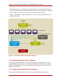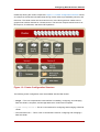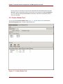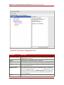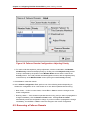
1
Configuring and Managing a Red Hat
Cluster
5.1
Red Hat Cluster for Red
Hat Enterprise Linux 5.1
ISBN: N/A
Publication date:
Configuring and Managing a Red Hat Cluster
Configuring and Managing a Red Hat Cluster describes the configuration and management of
Red Hat cluster systems for Red Hat Enterprise Linux 5.1 It does not include information about
Red Hat Linux Virtual Servers (LVS). Information about installing and configuring LVS is in a
separate document.
Configuring and Managing a Red Hat Cluster: Red Hat Cluster
for Red Hat Enterprise Linux 5.1
Copyright © You need to override this in your local ent file Red Hat, Inc.
Copyright © You need to override this in your local ent file Red Hat Inc.. This material may only be distributed subject to
the terms and conditions set forth in the Open Publication License, V1.0 or later with the restrictions noted below (the
latest version of the OPL is presently available at http://www.opencontent.org/openpub/).
Distribution of substantively modified versions of this document is prohibited without the explicit permission of the
copyright holder.
Distribution of the work or derivative of the work in any standard (paper) book form for commercial purposes is
prohibited unless prior permission is obtained from the copyright holder.
Red Hat and the Red Hat "Shadow Man" logo are registered trademarks of Red Hat, Inc. in the United States and other
countries.
All other trademarks referenced herein are the property of their respective owners.
The GPG fingerprint of the [email protected] key is:
CA 20 86 86 2B D6 9D FC 65 F6 EC C4 21 91 80 CD DB 42 A6 0E
1801 Varsity Drive
Raleigh, NC 27606-2072
USA
Phone: +1 919 754 3700
Phone: 888 733 4281
Fax: +1 919 754 3701
PO Box 13588
Research Triangle Park, NC 27709
USA
Configuring and Managing a Red Hat Cluster
Introduction .............................................................................................................. vii
1. Document Conventions ................................................................................ viii
2. Feedback ...................................................................................................... ix
1. Red Hat Cluster Configuration and Management Overview ....................................... 1
1. Configuration Basics ...................................................................................... 1
1.1. Setting Up Hardware ........................................................................... 1
1.2. Installing Red Hat Cluster software ....................................................... 2
1.3. Configuring Red Hat Cluster Software .................................................. 2
2. Conga ........................................................................................................... 4
3. system-config-cluster Cluster Administration GUI ....................................... 7
3.1. Cluster Configuration Tool ................................................................ 8
3.2. Cluster Status Tool ...........................................................................10
4. Command Line Administration Tools ..............................................................11
2. Before Configuring a Red Hat Cluster .....................................................................13
1. Compatible Hardware ....................................................................................13
2. Enabling IP Ports ..........................................................................................13
2.1. Enabling IP Ports on Cluster Nodes .....................................................13
2.2. Enabling IP Ports on Computers That Run luci ....................................14
2.3. Examples of iptables Rules ..............................................................15
3. Configuring ACPI For Use with Integrated Fence Devices ................................17
3.1. Disabling ACPI Soft-Off with chkconfig Management ..........................18
3.2. Disabling ACPI Soft-Off with the BIOS .................................................19
3.3. Disabling ACPI Completely in the grub.conf File .................................21
4. Configuring max_luns ....................................................................................22
5. Considerations for Using Quorum Disk ...........................................................22
6. Multicast Addresses ......................................................................................24
7. Considerations for Using Conga ....................................................................24
8. General Configuration Considerations ............................................................24
3. Configuring Red Hat Cluster With Conga ...............................................................27
1. Configuration Tasks ......................................................................................27
2. Starting luci and ricci ...................................................................................28
3. Creating A Cluster .........................................................................................29
4. Global Cluster Properties ...............................................................................30
5. Configuring Fence Devices ............................................................................32
5.1. Creating a Shared Fence Device .........................................................34
5.2. Modifying or Deleting a Fence Device ..................................................36
6. Configuring Cluster Members .........................................................................36
6.1. Initially Configuring Members ..............................................................36
6.2. Adding a Member to a Running Cluster ...............................................37
6.3. Deleting a Member from a Cluster .......................................................38
7. Configuring a Failover Domain .......................................................................39
7.1. Adding a Failover Domain ...................................................................41
7.2. Modifying a Failover Domain ...............................................................41
8. Adding Cluster Resources .............................................................................43
9. Adding a Cluster Service to the Cluster ..........................................................45
10. Configuring Cluster Storage .........................................................................47
v
Configuring and Managing a Red Hat Cluster
4. Managing Red Hat Cluster With Conga ..................................................................49
1. Starting, Stopping, and Deleting Clusters ........................................................49
2. Managing Cluster Nodes ...............................................................................50
3. Managing High-Availability Services ...............................................................51
4. Diagnosing and Correcting Problems in a Cluster ............................................52
5. Configuring Red Hat Cluster With system-config-cluster ....................................53
1. Configuration Tasks ......................................................................................53
2. Starting the Cluster Configuration Tool ........................................................54
3. Configuring Cluster Properties .......................................................................59
4. Configuring Fence Devices ............................................................................60
5. Adding and Deleting Members .......................................................................61
5.1. Adding a Member to a Cluster .............................................................61
5.2. Adding a Member to a Running Cluster ...............................................63
5.3. Deleting a Member from a Cluster .......................................................65
6. Configuring a Failover Domain .......................................................................66
6.1. Adding a Failover Domain ...................................................................68
6.2. Removing a Failover Domain ..............................................................70
6.3. Removing a Member from a Failover Domain .......................................71
7. Adding Cluster Resources .............................................................................72
8. Adding a Cluster Service to the Cluster ..........................................................74
9. Propagating The Configuration File: New Cluster ............................................77
10. Starting the Cluster Software .......................................................................78
6. Managing Red Hat Cluster With system-config-cluster ......................................79
1. Starting and Stopping the Cluster Software .....................................................79
2. Managing High-Availability Services ...............................................................80
3. Modifying the Cluster Configuration ................................................................82
4. Backing Up and Restoring the Cluster Database .............................................83
5. Disabling the Cluster Software .......................................................................84
6. Diagnosing and Correcting Problems in a Cluster ............................................85
A. Example of Setting Up Apache HTTP Server ..........................................................87
1. Apache HTTP Server Setup Overview ............................................................87
2. Configuring Shared Storage ...........................................................................88
3. Installing and Configuring the Apache HTTP Server ........................................88
B. Fence Device Parameters .....................................................................................93
C. Upgrading A Red Hat Cluster from RHEL 4 to RHEL 5 ............................................99
Index .....................................................................................................................103
vi
Introduction
This document provides information about installing, configuring and managing Red Hat Cluster
components. Red Hat Cluster components are part of Red Hat Cluster Suite and allow you to
connect a group of computers (called nodes or members) to work together as a cluster. This
document does not include information about installing, configuring, and managing Linux Virtual
Server (LVS) software. Information about that is in a separate document.
The audience of this document should have advanced working knowledge of Red Hat
Enterprise Linux and understand the concepts of clusters, storage, and server computing.
This document is organized as follows:
• Chapter 1, Red Hat Cluster Configuration and Management Overview
• Chapter 2, Before Configuring a Red Hat Cluster
• Chapter 3, Configuring Red Hat Cluster With Conga
• Chapter 4, Managing Red Hat Cluster With Conga
• Chapter 5, Configuring Red Hat Cluster With system-config-cluster
• Chapter 6, Managing Red Hat Cluster With system-config-cluster
• Appendix A, Example of Setting Up Apache HTTP Server
• Appendix B, Fence Device Parameters
• Appendix C, Upgrading A Red Hat Cluster from RHEL 4 to RHEL 5
For more information about Red Hat Enterprise Linux 5, refer to the following resources:
• Red Hat Enterprise Linux Installation Guide — Provides information regarding installation of
Red Hat Enterprise Linux 5.
• Red Hat Enterprise Linux Deployment Guide — Provides information regarding the
deployment, configuration and administration of Red Hat Enterprise Linux 5.
For more information about Red Hat Cluster Suite for Red Hat Enterprise Linux 5, refer to the
following resources:
• Red Hat Cluster Suite Overview — Provides a high level overview of the Red Hat Cluster
Suite.
• LVM Administrator's Guide: Configuration and Administration — Provides a description of the
Logical Volume Manager (LVM), including information on running LVM in a clustered
vii
Introduction
environment.
• Global File System: Configuration and Administration — Provides information about installing,
configuring, and maintaining Red Hat GFS (Red Hat Global File System).
• Using Device-Mapper Multipath — Provides information about using the Device-Mapper
Multipath feature of Red Hat Enterprise Linux 5.
• Using GNBD with Global File System — Provides an overview on using Global Network Block
Device (GNBD) with Red Hat GFS.
• Linux Virtual Server Administration — Provides information on configuring high-performance
systems and services with the Linux Virtual Server (LVS).
• Red Hat Cluster Suite Release Notes — Provides information about the current release of
Red Hat Cluster Suite.
Red Hat Cluster Suite documentation and other Red Hat documents are available in HTML,
PDF, and RPM versions on the Red Hat Enterprise Linux Documentation CD and online at
http://www.redhat.com/docs/.
1. Document Conventions
Certain words in this manual are represented in different fonts, styles, and weights. This
highlighting indicates that the word is part of a specific category. The categories include the
following:
Courier font
Courier font represents commands, file names and paths, and prompts .
When shown as below, it indicates computer output:
Desktop
Mail
about.html
backupfiles
logs
mail
paulwesterberg.png
reports
bold Courier font
Bold Courier font represents text that you are to type, such as: service jonas start
If you have to run a command as root, the root prompt (#) precedes the command:
# gconftool-2
italic Courier font
viii
Feedback
Italic Courier font represents a variable, such as an installation directory:
install_dir/bin/
bold font
Bold font represents application programs and text found on a graphical interface.
When shown like this: OK , it indicates a button on a graphical application interface.
Additionally, the manual uses different strategies to draw your attention to pieces of information.
In order of how critical the information is to you, these items are marked as follows:
Note
A note is typically information that you need to understand the behavior of the
system.
Tip
A tip is typically an alternative way of performing a task.
Important
Important information is necessary, but possibly unexpected, such as a
configuration change that will not persist after a reboot.
Caution
A caution indicates an act that would violate your support agreement, such as
recompiling the kernel.
Warning
A warning indicates potential data loss, as may happen when tuning hardware
for maximum performance.
2. Feedback
ix
Introduction
If you spot a typo, or if you have thought of a way to make this manual better, we would love to
hear from you. Please submit a report in Bugzilla (http://bugzilla.redhat.com/bugzilla/) against
the component Documentation-cluster.
Be sure to mention the manual's identifier:
Cluster_Administration RHEL 5.1 (2008-01-10T14:58)
By mentioning this manual's identifier, we know exactly which version of the guide you have.
If you have a suggestion for improving the documentation, try to be as specific as possible. If
you have found an error, please include the section number and some of the surrounding text
so we can find it easily.
x
Chapter 1.
Red Hat Cluster Configuration and
Management Overview
Red Hat Cluster allows you to connect a group of computers (called nodes or members) to work
together as a cluster. You can use Red Hat Cluster to suit your clustering needs (for example,
setting up a cluster for sharing files on a GFS file system or setting up service failover).
1. Configuration Basics
To set up a cluster, you must connect the nodes to certain cluster hardware and configure the
nodes into the cluster environment. This chapter provides an overview of cluster configuration
and management, and tools available for configuring and managing a Red Hat Cluster.
Configuring and managing a Red Hat Cluster consists of the following basic steps:
1. Setting up hardware. Refer to Section 1.1, “Setting Up Hardware”.
2. Installing Red Hat Cluster software. Refer to Section 1.2, “Installing Red Hat Cluster
software”.
3. Configuring Red Hat Cluster Software. Refer to Section 1.3, “Configuring Red Hat Cluster
Software”.
1.1. Setting Up Hardware
Setting up hardware consists of connecting cluster nodes to other hardware required to run a
Red Hat Cluster. The amount and type of hardware varies according to the purpose and
availability requirements of the cluster. Typically, an enterprise-level cluster requires the
following type of hardware (refer to Figure 1.1, “Red Hat Cluster Hardware Overview”). For
considerations about hardware and other cluster configuration concerns, refer to Chapter 2,
Before Configuring a Red Hat Cluster or check with an authorized Red Hat representative.
• Cluster nodes — Computers that are capable of running Red Hat Enterprise Linux 5 software,
with at least 1GB of RAM.
• Ethernet switch or hub for public network — This is required for client access to the cluster.
• Ethernet switch or hub for private network — This is required for communication among the
cluster nodes and other cluster hardware such as network power switches and Fibre Channel
switches.
• Network power switch — A network power switch is recommended to perform fencing in an
enterprise-level cluster.
1
Chapter 1. Red Hat Cluster Configuration and Management Overview
• Fibre Channel switch — A Fibre Channel switch provides access to Fibre Channel storage.
Other options are available for storage according to the type of storage interface; for example,
iSCSI or GNBD. A Fibre Channel switch can be configured to perform fencing.
• Storage — Some type of storage is required for a cluster. The type required depends on the
purpose of the cluster.
Figure 1.1. Red Hat Cluster Hardware Overview
1.2. Installing Red Hat Cluster software
To install Red Hat Cluster software, you must have entitlements for the software. If you are
using the Conga configuration GUI, you can let it install the cluster software. If you are using
other tools to configure the cluster, secure and install the software as you would with Red Hat
Enterprise Linux software.
1.3. Configuring Red Hat Cluster Software
Configuring Red Hat Cluster software consists of using configuration tools to specify the
2
Configuring Red Hat Cluster Software
relationship among the cluster components. Figure 1.2, “Cluster Configuration Structure” shows
an example of the hierarchical relationship among cluster nodes, high-availability services, and
resources. The cluster nodes are connected to one or more fencing devices. Nodes can be
grouped into a failover domain for a cluster service. The services comprise resources such as
NFS exports, IP addresses, and shared GFS partitions.
Figure 1.2. Cluster Configuration Structure
The following cluster configuration tools are available with Red Hat Cluster:
• Conga — This is a comprehensive user interface for installing, configuring, and managing
Red Hat clusters, computers, and storage attached to clusters and computers.
• system-config-cluster — This is a user interface for configuring and managing a Red Hat
cluster.
• Command line tools — This is a set of command line tools for configuring and managing a
Red Hat cluster.
3
Chapter 1. Red Hat Cluster Configuration and Management Overview
A brief overview of each configuration tool is provided in the following sections:
• Section 2, “Conga”
• Section 3, “system-config-cluster Cluster Administration GUI”
• Section 4, “Command Line Administration Tools”
In addition, information about using Conga and system-config-cluster is provided in
subsequent chapters of this document. Information about the command line tools is available in
the man pages for the tools.
2. Conga
Conga is an integrated set of software components that provides centralized configuration and
management of Red Hat clusters and storage. Conga provides the following major features:
• One Web interface for managing cluster and storage
• Automated Deployment of Cluster Data and Supporting Packages
• Easy Integration with Existing Clusters
• No Need to Re-Authenticate
• Integration of Cluster Status and Logs
• Fine-Grained Control over User Permissions
The primary components in Conga are luci and ricci, which are separately installable. luci is a
server that runs on one computer and communicates with multiple clusters and computers via
ricci. ricci is an agent that runs on each computer (either a cluster member or a standalone
computer) managed by Conga.
luci is accessible through a Web browser and provides three major functions that are
accessible through the following tabs:
• homebase — Provides tools for adding and deleting computers, adding and deleting users,
and configuring user privileges. Only a system administrator is allowed to access this tab.
• cluster — Provides tools for creating and configuring clusters. Each instance of luci lists
clusters that have been set up with that luci. A system administrator can administer all
clusters listed on this tab. Other users can administer only clusters that the user has
permission to manage (granted by an administrator).
• storage — Provides tools for remote administration of storage. With the tools on this tab, you
4
Conga
can manage storage on computers whether they belong to a cluster or not.
To administer a cluster or storage, an administrator adds (or registers) a cluster or a computer
to a luci server. When a cluster or a computer is registered with luci, the FQDN hostname or IP
address of each computer is stored in a luci database.
You can populate the database of one luci instance from another luciinstance. That capability
provides a means of replicating a luci server instance and provides an efficient upgrade and
testing path. When you install an instance of luci, its database is empty. However, you can
import part or all of a luci database from an existing luci server when deploying a new luci
server.
Each luci instance has one user at initial installation — admin. Only the admin user may add
systems to a luci server. Also, the admin user can create additional user accounts and
determine which users are allowed to access clusters and computers registered in the luci
database. It is possible to import users as a batch operation in a new luci server, just as it is
possible to import clusters and computers.
When a computer is added to a luci server to be administered, authentication is done once. No
authentication is necessary from then on (unless the certificate used is revoked by a CA). After
that, you can remotely configure and manage clusters and storage through the luci user
interface. luci and ricci communicate with each other via XML.
The following figures show sample displays of the three major luci tabs: homebase, cluster,
and storage.
For more information about Conga, refer to Chapter 3, Configuring Red Hat Cluster With
Conga, Chapter 4, Managing Red Hat Cluster With Conga, and the online help available with
the luci server.
5
Chapter 1. Red Hat Cluster Configuration and Management Overview
Figure 1.3. luci homebase Tab
Figure 1.4. luci cluster Tab
6
system-config-cluster Cluster
Figure 1.5. luci storage Tab
3. system-config-cluster Cluster Administration GUI
This section provides an overview of the cluster administration graphical user interface (GUI)
available with Red Hat Cluster Suite — system-config-cluster. It is for use with the cluster
infrastructure and the high-availability service management components.
system-config-cluster consists of two major functions: the Cluster Configuration Tool and
the Cluster Status Tool. The Cluster Configuration Tool provides the capability to create,
edit, and propagate the cluster configuration file (/etc/cluster/cluster.conf). The Cluster
Status Tool provides the capability to manage high-availability services. The following sections
summarize those functions.
Note
7
Chapter 1. Red Hat Cluster Configuration and Management Overview
While system-config-cluster provides several convenient tools for configuring
and managing a Red Hat Cluster, the newer, more comprehensive tool, Conga,
provides more convenience and flexibility than system-config-cluster.
3.1. Cluster Configuration Tool
You can access the Cluster Configuration Tool (Figure 1.6, “Cluster Configuration Tool”)
through the Cluster Configuration tab in the Cluster Administration GUI.
Figure 1.6. Cluster Configuration Tool
8
Administration GUI
The Cluster Configuration Tool represents cluster configuration components in the
configuration file (/etc/cluster/cluster.conf) with a hierarchical graphical display in the left
panel. A triangle icon to the left of a component name indicates that the component has one or
more subordinate components assigned to it. Clicking the triangle icon expands and collapses
the portion of the tree below a component. The components displayed in the GUI are
summarized as follows:
• Cluster Nodes — Displays cluster nodes. Nodes are represented by name as subordinate
elements under Cluster Nodes. Using configuration buttons at the bottom of the right frame
(below Properties), you can add nodes, delete nodes, edit node properties, and configure
fencing methods for each node.
• Fence Devices — Displays fence devices. Fence devices are represented as subordinate
elements under Fence Devices. Using configuration buttons at the bottom of the right frame
(below Properties), you can add fence devices, delete fence devices, and edit fence-device
properties. Fence devices must be defined before you can configure fencing (with the
Manage Fencing For This Node button) for each node.
• Managed Resources — Displays failover domains, resources, and services.
• Failover Domains — For configuring one or more subsets of cluster nodes used to run a
high-availability service in the event of a node failure. Failover domains are represented as
subordinate elements under Failover Domains. Using configuration buttons at the bottom
of the right frame (below Properties), you can create failover domains (when Failover
Domains is selected) or edit failover domain properties (when a failover domain is
selected).
• Resources — For configuring shared resources to be used by high-availability services.
Shared resources consist of file systems, IP addresses, NFS mounts and exports, and
user-created scripts that are available to any high-availability service in the cluster.
Resources are represented as subordinate elements under Resources. Using
configuration buttons at the bottom of the right frame (below Properties), you can create
resources (when Resources is selected) or edit resource properties (when a resource is
selected).
Note
The Cluster Configuration Tool provides the capability to configure private
resources, also. A private resource is a resource that is configured for use with
only one service. You can configure a private resource within a Service
component in the GUI.
• Services — For creating and configuring high-availability services. A service is configured
by assigning resources (shared or private), assigning a failover domain, and defining a
9
Chapter 1. Red Hat Cluster Configuration and Management Overview
recovery policy for the service. Services are represented as subordinate elements under
Services. Using configuration buttons at the bottom of the right frame (below Properties),
you can create services (when Services is selected) or edit service properties (when a
service is selected).
3.2. Cluster Status Tool
You can access the Cluster Status Tool (Figure 1.7, “Cluster Status Tool”) through the
Cluster Management tab in Cluster Administration GUI.
Figure 1.7. Cluster Status Tool
10
Command Line Administration Tools
The nodes and services displayed in the Cluster Status Tool are determined by the cluster
configuration file (/etc/cluster/cluster.conf). You can use the Cluster Status Tool to
enable, disable, restart, or relocate a high-availability service.
4. Command Line Administration Tools
In addition to Conga and the system-config-cluster Cluster Administration GUI, command
line tools are available for administering the cluster infrastructure and the high-availability
service management components. The command line tools are used by the Cluster
Administration GUI and init scripts supplied by Red Hat. Table 1.1, “Command Line Tools”
summarizes the command line tools.
Command Line
Tool
Used With
Purpose
ccs_tool —
Cluster
Infrastructure
ccs_tool is a program for making online updates to the
Cluster
Infrastructure
cman_tool is a program that manages the CMAN
Cluster
Infrastructure
fence_tool is a program used to join or leave the
High-availability
Service
Management
Components
The clustat command displays the status of the
cluster. It shows membership information, quorum view,
and the state of all configured user services. For more
information about this tool, refer to the clustat(8) man
page.
High-availability
Service
Management
Components
The clusvcadm command allows you to enable,
disable, relocate, and restart high-availability services
in a cluster. For more information about this tool, refer
to the clusvcadm(8) man page.
Cluster
Configuration
System Tool
cman_tool —
Cluster
Management
Tool
fence_tool —
Fence Tool
clustat —
Cluster Status
Utility
clusvcadm —
Cluster User
Service
Administration
Utility
cluster configuration file. It provides the capability to
create and modify cluster infrastructure components
(for example, creating a cluster, adding and removing a
node). For more information about this tool, refer to the
ccs_tool(8) man page.
cluster manager. It provides the capability to join a
cluster, leave a cluster, kill a node, or change the
expected quorum votes of a node in a cluster. For more
information about this tool, refer to the cman_tool(8)
man page.
default fence domain. Specifically, it starts the fence
daemon (fenced) to join the domain and kills fenced to
leave the domain. For more information about this tool,
refer to the fence_tool(8) man page.
Table 1.1. Command Line Tools
11
12
Chapter 2.
Before Configuring a Red Hat
Cluster
This chapter describes tasks to perform and considerations to make before installing and
configuring a Red Hat Cluster, and consists of the following sections:
• Section 1, “Compatible Hardware”
• Section 2, “Enabling IP Ports”
• Section 3, “Configuring ACPI For Use with Integrated Fence Devices”
• Section 4, “Configuring max_luns”
• Section 5, “Considerations for Using Quorum Disk”
• Section 6, “Multicast Addresses”
• Section 7, “Considerations for Using Conga”
• Section 8, “General Configuration Considerations”
1. Compatible Hardware
Before configuring Red Hat Cluster software, make sure that your cluster uses appropriate
hardware (for example, supported fence devices, storage devices, and Fibre Channel switches).
Refer to the hardware configuration guidelines at http://www.redhat.com/cluster_suite/hardware/
for the most current hardware compatibility information.
2. Enabling IP Ports
Before deploying a Red Hat Cluster, you must enable certain IP ports on the cluster nodes and
on computers that run luci (the Conga user interface server). The following sections specify the
IP ports to be enabled and provide examples of iptables rules for enabling the ports:
• Section 2.1, “Enabling IP Ports on Cluster Nodes”
• Section 2.2, “Enabling IP Ports on Computers That Run luci”
• Section 2.3, “Examples of iptables Rules”
2.1. Enabling IP Ports on Cluster Nodes
To allow Red Hat Cluster nodes to communicate with each other, you must enable the IP ports
assigned to certain Red Hat Cluster components. Table 2.1, “Enabled IP Ports on Red Hat
13
Chapter 2. Before Configuring a Red Hat Cluster
Cluster Nodes” lists the IP port numbers, their respective protocols, the components to which
the port numbers are assigned, and references to iptables rule examples. At each cluster
node, enable IP ports according to Table 2.1, “Enabled IP Ports on Red Hat Cluster Nodes”. (All
examples are in Section 2.3, “Examples of iptables Rules”.)
IP Port
Number
Protocol
Component
Reference to Example of
iptables Rules
5404,
5405
UDP
cman (Cluster Manager)
Example 2.1, “Port 5404, 5405:
cman”
11111
TCP
ricci (part of Conga remote
agent)
Example 2.3, “Port 11111: ricci
(Cluster Node and Computer
Running luci)”
gnbd (Global Network Block
Example 2.4, “Port 14567: gnbd”
14567
TCP
Device)
16851
TCP
modclusterd (part of Conga
remote agent)
Example 2.5, “Port 16851:
modclusterd”
21064
TCP
dlm (Distributed Lock Manager)
Example 2.6, “Port 21064: dlm”
41966,
41967,
41968,
41969
TCP
rgmanager (high-availability
Example 2.7, “Ports 41966,
41967, 41968, 41969:
rgmanager”
50006,
50008,
50009
TCP
50007
UDP
service management)
ccsd (Cluster Configuration
System daemon)
ccsd (Cluster Configuration
System daemon)
Example 2.8, “Ports 50006,
50008, 50009: ccsd (TCP)”
Example 2.9, “Port 50007: ccsd
(UDP)”
Table 2.1. Enabled IP Ports on Red Hat Cluster Nodes
2.2. Enabling IP Ports on Computers That Run luci
To allow client computers to communicate with a computer that runs luci (the Conga user
interface server), and to allow a computer that runs luci to communicate with ricci in the cluster
nodes, you must enable the IP ports assigned to luci and ricci. Table 2.2, “Enabled IP Ports on
a Computer That Runs luci” lists the IP port numbers, their respective protocols, the
components to which the port numbers are assigned, and references to iptables rule
examples. At each computer that runs luci, enable IP ports according to Table 2.1, “Enabled IP
Ports on Red Hat Cluster Nodes”. (All examples are in Section 2.3, “Examples of iptables
Rules”.)
Note
14
Examples of iptables Rules
If a cluster node is running luci, port 11111 should already have been enabled.
IP Port
Number
Protocol
Component
Reference to Example of
iptables Rules
8084
TCP
luci (Conga user interface
server)
Example 2.2, “Port 8084: luci
(Cluster Node or Computer
Running luci)”
11111
TCP
ricci (Conga remote agent)
Example 2.3, “Port 11111: ricci
(Cluster Node and Computer
Running luci)”
Table 2.2. Enabled IP Ports on a Computer That Runs luci
2.3. Examples of iptables Rules
This section provides iptables rule examples for enabling IP ports on Red Hat Cluster nodes
and computers that run luci. The examples enable IP ports for a computer having an IP
address of 10.10.10.200, using a subnet mask of 10.10.10.0/24.
Note
Examples are for cluster nodes unless otherwise noted in the example titles.
iptables -A INPUT -i 10.10.10.200 -m multiport -m state --state NEW -p udp
-s 10.10.10.0/24 -d 10.10.10.0/24 --dports 5404,5405 -j ACCEPT
Example 2.1. Port 5404, 5405: cman
-A INPUT -i 10.10.10.200 -m state --state NEW -m multiport -p tcp -s
10.10.10.0/24 -d 10.10.10.0/24 --dports 8084 -j ACCEPT
Example 2.2. Port 8084: luci (Cluster Node or Computer Running luci)
-A INPUT -i 10.10.10.200 -m state --state NEW -m multiport -p tcp -s
15
Chapter 2. Before Configuring a Red Hat Cluster
10.10.10.0/24 -d 10.10.10.0/24 --dports 11111 -j ACCEPT
Example 2.3. Port 11111: ricci (Cluster Node and Computer Running luci)
-A INPUT -i 10.10.10.200 -m state --state NEW -m multiport -p tcp -s
10.10.10.0/24 -d 10.10.10.0/24 --dports 14567 -j ACCEPT
Example 2.4. Port 14567: gnbd
-A INPUT -i 10.10.10.200 -m state --state NEW -m multiport -p tcp -s
10.10.10.0/24 -d 10.10.10.0/24 --dports 16851 -j ACCEPT
Example 2.5. Port 16851: modclusterd
-A INPUT -i 10.10.10.200 -m state --state NEW -m multiport -p tcp -s
10.10.10.0/24 -d 10.10.10.0/24 --dports 21064 -j ACCEPT
Example 2.6. Port 21064: dlm
-A INPUT -i 10.10.10.200 -m state --state NEW -m multiport -p tcp -s
10.10.10.0/24 -d 10.10.10.0/24 --dports 41966,41967,41968,41969 -j ACCEPT
Example 2.7. Ports 41966, 41967, 41968, 41969: rgmanager
-A INPUT -i 10.10.10.200 -m state --state NEW -m multiport -p tcp -s
10.10.10.0/24 -d 10.10.10.0/24 --dports 50006,50008,50009 -j ACCEPT
Example 2.8. Ports 50006, 50008, 50009: ccsd (TCP)
-A INPUT -i 10.10.10.200 -m state --state NEW -m multiport -p udp -s
16
Configuring ACPI For Use with Integrated
10.10.10.0/24 -d 10.10.10.0/24 --dports 50007 -j ACCEPT
Example 2.9. Port 50007: ccsd (UDP)
3. Configuring ACPI For Use with Integrated Fence
Devices
If your cluster uses integrated fence devices, you must configure ACPI (Advanced Configuration
and Power Interface) to ensure immediate and complete fencing.
Note
For the most current information about integrated fence devices supported by
Red Hat Cluster Suite, refer to http://www.redhat.com/cluster_suite/hardware/
[http://www.redhat.com/cluster_suite/hardware/].
If a cluster node is configured to be fenced by an integrated fence device, disable ACPI Soft-Off
for that node. Disabling ACPI Soft-Off allows an integrated fence device to turn off a node
immediately and completely rather than attempting a clean shutdown (for example, shutdown
-h now). Otherwise, if ACPI Soft-Off is enabled, an integrated fence device can take four or
more seconds to turn off a node (refer to note that follows). In addition, if ACPI Soft-Off is
enabled and a node panics or freezes during shutdown, an integrated fence device may not be
able to turn off the node. Under those circumstances, fencing is delayed or unsuccessful.
Consequently, when a node is fenced with an integrated fence device and ACPI Soft-Off is
enabled, a cluster recovers slowly or requires administrative intervention to recover.
Note
The amount of time required to fence a node depends on the integrated fence
device used. Some integrated fence devices perform the equivalent of pressing
and holding the power button; therefore, the fence device turns off the node in
four to five seconds. Other integrated fence devices perform the equivalent of
pressing the power button momentarily, relying on the operating system to turn
off the node; therefore, the fence device turns off the node in a time span much
longer than four to five seconds.
To disable ACPI Soft-Off, use chkconfig management and verify that the node turns off
immediately when fenced. The preferred way to disable ACPI Soft-Off is with chkconfig
management: however, if that method is not satisfactory for your cluster, you can disable ACPI
17
Chapter 2. Before Configuring a Red Hat Cluster
Soft-Off with one of the following alternate methods:
• Changing the BIOS setting to "instant-off" or an equivalent setting that turns off the node
without delay
Note
Disabling ACPI Soft-Off with the BIOS may not be possible with some
computers.
• Appending acpi=off to the kernel boot command line of the /boot/grub/grub.conf file
Important
This method completely disables ACPI; some computers do not boot correctly if
ACPI is completely disabled. Use this method only if the other methods are not
effective for your cluster.
The following sections provide procedures for the preferred method and alternate methods of
disabling ACPI Soft-Off:
• Section 3.1, “Disabling ACPI Soft-Off with chkconfig Management” — Preferred method
• Section 3.2, “Disabling ACPI Soft-Off with the BIOS” — First alternate method
• Section 3.3, “Disabling ACPI Completely in the grub.conf File” — Second alternate method
3.1. Disabling ACPI Soft-Off with chkconfig Management
You can use chkconfig management to disable ACPI Soft-Off either by removing the ACPI
daemon (acpid) from chkconfig management or by turning off acpid.
Note
This is the preferred method of disabling ACPI Soft-Off.
Disable ACPI Soft-Off with chkconfig management at each cluster node as follows:
1. Run either of the following commands:
18
Fence Devices
• chkconfig --del acpid — This command removes acpid from chkconfig
management.
— OR —
• chkconfig --level 2345 acpid off — This command turns off acpid.
2. Reboot the node.
3. When the cluster is configured and running, verify that the node turns off immediately when
fenced.
Tip
You can fence the node with the fence_node command or Conga.
3.2. Disabling ACPI Soft-Off with the BIOS
The preferred method of disabling ACPI Soft-Off is with chkconfig management (Section 3.1,
“Disabling ACPI Soft-Off with chkconfig Management”). However, if the preferred method is
not effective for your cluster, follow the procedure in this section.
Note
Disabling ACPI Soft-Off with the BIOS may not be possible with some
computers.
You can disable ACPI Soft-Off by configuring the BIOS of each cluster node as follows:
1. Reboot the node and start the BIOS CMOS Setup Utility program.
2. Navigate to the Power menu (or equivalent power management menu).
3. At the Power menu, set the Soft-Off by PWR-BTTN function (or equivalent) to Instant-Off
(or the equivalent setting that turns off the node via the power button without delay).
Example 2.10, “BIOS CMOS Setup Utility: Soft-Off by PWR-BTTN set to Instant-Off”
shows a Power menu with ACPI Function set to Enabled and Soft-Off by PWR-BTTN set
to Instant-Off.
19
Chapter 2. Before Configuring a Red Hat Cluster
Note
The equivalents to ACPI Function, Soft-Off by PWR-BTTN, and Instant-Off
may vary among computers. However, the objective of this procedure is to
configure the BIOS so that the computer is turned off via the power button
without delay.
4. Exit the BIOS CMOS Setup Utility program, saving the BIOS configuration.
5. When the cluster is configured and running, verify that the node turns off immediately when
fenced.
Tip
You can fence the node with the fence_node command or Conga.
+-------------------------------------------------|------------------------+
|
ACPI Function
[Enabled]
|
Item Help
|
|
ACPI Suspend Type
[S1(POS)]
|------------------------|
| x Run VGABIOS if S3 Resume
Auto
| Menu Level
*
|
|
Suspend Mode
[Disabled]
|
|
|
HDD Power Down
[Disabled]
|
|
|
Soft-Off by PWR-BTTN
[Instant-Off]
|
|
|
CPU THRM-Throttling
[50.0%]
|
|
|
Wake-Up by PCI card
[Enabled]
|
|
|
Power On by Ring
[Enabled]
|
|
|
Wake Up On LAN
[Enabled]
|
|
| x USB KB Wake-Up From S3
Disabled
|
|
|
Resume by Alarm
[Disabled]
|
|
| x Date(of Month) Alarm
0
|
|
| x Time(hh:mm:ss) Alarm
0 : 0 : 0
|
|
|
POWER ON Function
[BUTTON ONLY]
|
|
| x KB Power ON Password
Enter
|
|
| x Hot Key Power ON
Ctrl-F1
|
|
|
|
|
|
|
|
+-------------------------------------------------|------------------------+
This example shows ACPI Function set to Enabled, and Soft-Off by PWR-BTTN set to
Instant-Off.
Example 2.10. BIOS
Instant-Off
20
CMOS Setup Utility:
Soft-Off by PWR-BTTN set to
Disabling ACPI Completely in the grub.conf
3.3. Disabling ACPI Completely in the grub.conf File
The preferred method of disabling ACPI Soft-Off is with chkconfig management (Section 3.1,
“Disabling ACPI Soft-Off with chkconfig Management”). If the preferred method is not effective
for your cluster, you can disable ACPI Soft-Off with the BIOS power management (Section 3.2,
“Disabling ACPI Soft-Off with the BIOS”). If neither of those methods is effective for your cluster,
you can disable ACPI completely by appending acpi=off to the kernel boot command line in
the grub.conf file.
Important
This method completely disables ACPI; some computers do not boot correctly if
ACPI is completely disabled. Use this method only if the other methods are not
effective for your cluster.
You can disable ACPI completely by editing the grub.conf file of each cluster node as follows:
1. Open /boot/grub/grub.conf with a text editor.
2. Append acpi=off to the kernel boot command line in /boot/grub/grub.conf (refer to
Example 2.11, “Kernel Boot Command Line with acpi=off Appended to It”).
3. Reboot the node.
4. When the cluster is configured and running, verify that the node turns off immediately when
fenced.
Tip
You can fence the node with the fence_node command or Conga.
# grub.conf generated by anaconda
#
# Note that you do not have to rerun grub after making changes to this file
# NOTICE: You have a /boot partition. This means that
#
all kernel and initrd paths are relative to /boot/, eg.
#
root (hd0,0)
#
kernel /vmlinuz-version ro root=/dev/VolGroup00/LogVol00
#
initrd /initrd-version.img
#boot=/dev/hda
default=0
timeout=5
serial --unit=0 --speed=115200
terminal --timeout=5 serial console
21
Chapter 2. Before Configuring a Red Hat Cluster
title Red Hat Enterprise Linux Server (2.6.18-36.el5)
root (hd0,0)
kernel /vmlinuz-2.6.18-36.el5 ro root=/dev/VolGroup00/LogVol00
console=ttyS0,115200n8 acpi=off
initrd /initrd-2.6.18-36.el5.img
In this example, acpi=off has been appended to the kernel boot command line — the line
starting with "kernel /vmlinuz-2.6.18-36.el5".
Example 2.11. Kernel Boot Command Line with acpi=off Appended to It
4. Configuring max_luns
It is not necessary to configure max_luns in Red Hat Enterprise Linux 5.
In Red Hat Enterprise Linux releases prior to Red Hat Enterprise Linux 5, if RAID storage in a
cluster presents multiple LUNs, it is necessary to enable access to those LUNs by configuring
max_luns (or max_scsi_luns for 2.4 kernels) in the /etc/modprobe.conf file of each node. In
Red Hat Enterprise Linux 5, cluster nodes detect multiple LUNs without intervention required; it
is not necessary to configure max_luns to detect multiple LUNs.
5. Considerations for Using Quorum Disk
Quorum Disk is a disk-based quorum daemon, qdiskd, that provides supplemental heuristics to
determine node fitness. With heuristics you can determine factors that are important to the
operation of the node in the event of a network partition. For example, in a four-node cluster
with a 3:1 split, ordinarily, the three nodes automatically "win" because of the three-to-one
majority. Under those circumstances, the one node is fenced. With qdiskd however, you can
set up heuristics that allow the one node to win based on access to a critical resource (for
example, a critical network path). If your cluster requires additional methods of determining
node health, then you should configure qdiskd to meet those needs.
Note
Configuring qdiskd is not required unless you have special requirements for
node health. An example of a special requirement is an "all-but-one"
configuration. In an all-but-one configuration, qdiskd is configured to provide
enough quorum votes to maintain quorum even though only one node is working.
22
File
Important
Overall, heuristics and other qdiskd parameters for your Red Hat Cluster
depend on the site environment and special requirements needed. To
understand the use of heuristics and other qdiskd parameters, refer to the
qdisk(5) man page. If you require assistance understanding and using qdiskd for
your site, contact an authorized Red Hat support representative.
If you need to use qdiskd, you should take into account the following considerations:
Cluster node votes
Each cluster node should have the same number of votes.
CMAN membership timeout value
The CMAN membership timeout value (the time a node needs to be unresponsive before
CMAN considers that node to be dead, and not a member) should be at least two times that
of the qdiskd membership timeout value. The reason is because the quorum daemon must
detect failed nodes on its own, and can take much longer to do so than CMAN. The default
value for CMAN membership timeout is 10 seconds. Other site-specific conditions may
affect the relationship between the membership timeout values of CMAN and qdiskd. For
assistance with adjusting the CMAN membership timeout value, contact an authorized Red
Hat support representative.
Fencing
To ensure reliable fencing when using qdiskd, use power fencing. While other types of
fencing (such as watchdog timers and software-based solutions to reboot a node internally)
can be reliable for clusters not configured with qdiskd, they are not reliable for a cluster
configured with qdiskd.
Maximum nodes
A cluster configured with qdiskd supports a maximum of 16 nodes. The reason for the limit
is because of scalability; increasing the node count increases the amount of synchronous
I/O contention on the shared quorum disk device.
Quorum disk device
A quorum disk device should be a shared block device with concurrent read/write access by
all nodes in a cluster. The minimum size of the block device is 10 Megabytes. Examples of
shared block devices that can be used by qdiskd are a multi-port SCSI RAID array, a Fibre
Channel RAID SAN, or a RAID-configured iSCSI target. You can create a quorum disk
device with mkqdisk, the Cluster Quorum Disk Utility. For information about using the utility
refer to the mkqdisk(8) man page.
23
Chapter 2. Before Configuring a Red Hat Cluster
Note
Using JBOD as a quorum disk is not recommended. A JBOD cannot provide
dependable performance and therefore may not allow a node to write to it quickly
enough. If a node is unable to write to a quorum disk device quickly enough, the
node is falsely evicted from a cluster.
6. Multicast Addresses
Red Hat Cluster nodes communicate among each other using multicast addresses. Therefore,
each network switch and associated networking equipment in a Red Hat Cluster must be
configured to enable multicast addresses and support IGMP (Internet Group Management
Protocol). Ensure that each network switch and associated networking equipment in a Red Hat
Cluster are capable of supporting multicast addresses and IGMP; if they are, ensure that
multicast addressing and IGMP are enabled. Without multicast and IGMP, not all nodes can
participate in a cluster, causing the cluster to fail.
Note
Procedures for configuring network switches and associated networking
equipment vary according each product. Refer to the appropriate vendor
documentation or other information about configuring network switches and
associated networking equipment to enable multicast addresses and IGMP.
7. Considerations for Using Conga
When using Conga to configure and manage your Red Hat Cluster, make sure that each
computer running luci (the Conga user interface server) is running on the same network that
the cluster is using for cluster communication. Otherwise, luci cannot configure the nodes to
communicate on the right network. If the computer running luci is on another network (for
example, a public network rather than a private network that the cluster is communicating on),
contact an authorized Red Hat support representative to make sure that the appropriate host
name is configured for each cluster node.
8. General Configuration Considerations
You can configure a Red Hat Cluster in a variety of ways to suit your needs. Take into account
the following considerations when you plan, configure, and implement your Red Hat Cluster.
24
General Configuration Considerations
No-single-point-of-failure hardware configuration
Clusters can include a dual-controller RAID array, multiple bonded network channels,
multiple paths between cluster members and storage, and redundant un-interruptible power
supply (UPS) systems to ensure that no single failure results in application down time or
loss of data.
Alternatively, a low-cost cluster can be set up to provide less availability than a
no-single-point-of-failure cluster. For example, you can set up a cluster with a
single-controller RAID array and only a single Ethernet channel.
Certain low-cost alternatives, such as host RAID controllers, software RAID without cluster
support, and multi-initiator parallel SCSI configurations are not compatible or appropriate for
use as shared cluster storage.
Data integrity assurance
To ensure data integrity, only one node can run a cluster service and access cluster-service
data at a time. The use of power switches in the cluster hardware configuration enables a
node to power-cycle another node before restarting that node's cluster services during a
failover process. This prevents two nodes from simultaneously accessing the same data
and corrupting it. It is strongly recommended that fence devices (hardware or software
solutions that remotely power, shutdown, and reboot cluster nodes) are used to guarantee
data integrity under all failure conditions. Watchdog timers provide an alternative way to to
ensure correct operation of cluster service failover.
Ethernet channel bonding
Cluster quorum and node health is determined by communication of messages among
cluster nodes via Ethernet. In addition, cluster nodes use Ethernet for a variety of other
critical cluster functions (for example, fencing). With Ethernet channel bonding, multiple
Ethernet interfaces are configured to behave as one, reducing the risk of a
single-point-of-failure in the typical switched Ethernet connection among cluster nodes and
other cluster hardware.
25
26
Chapter 3.
Configuring Red Hat Cluster With
Conga
This chapter describes how to configure Red Hat Cluster software using Conga, and consists of
the following sections:
• Section 1, “Configuration Tasks”
• Section 2, “Starting luci and ricci”
• Section 3, “Creating A Cluster”
• Section 4, “Global Cluster Properties”
• Section 5, “Configuring Fence Devices”
• Section 6, “Configuring Cluster Members”
• Section 7, “Configuring a Failover Domain”
• Section 8, “Adding Cluster Resources”
• Section 9, “Adding a Cluster Service to the Cluster”
• Section 10, “Configuring Cluster Storage”
1. Configuration Tasks
Configuring Red Hat Cluster software with Conga consists of the following steps:
1. Configuring and running the Conga configuration user interface — the luci server. Refer to
Section 2, “Starting luci and ricci”.
2. Creating a cluster. Refer to Section 3, “Creating A Cluster”.
3. Configuring global cluster properties. Refer to Section 4, “Global Cluster Properties”.
4. Configuring fence devices. Refer to Section 5, “Configuring Fence Devices”.
5. Configuring cluster members. Refer to Section 6, “Configuring Cluster Members”.
6. Creating failover domains. Refer to Section 7, “Configuring a Failover Domain”.
7. Creating resources. Refer to Section 8, “Adding Cluster Resources”.
8. Creating cluster services. Refer to Section 9, “Adding a Cluster Service to the Cluster”.
27
Chapter 3. Configuring Red Hat Cluster With Conga
9. Configuring storage. Refer to Section 10, “Configuring Cluster Storage”.
2. Starting luci and ricci
To administer Red Hat Clusters with Conga, install and run luci and ricci as follows:
1. At each node to be administered by Conga, install the ricci agent. For example:
# yum install ricci
2. At each node to be administered by Conga, start ricci. For example:
# service ricci start
Starting ricci:
[
OK
]
3. Select a computer to host luci and install the luci software on that computer. For example:
# yum install luci
Note
Typically, a computer in a server cage or a data center hosts luci; however, a
cluster computer can host luci.
4. At the computer running luci, initialize the luci server using the luci_admin init command.
For example:
# luci_admin init
Initializing the Luci server
Creating the 'admin' user
Enter password: <Type password and press ENTER.>
Confirm password: <Re-type password and press ENTER.>
Please wait...
The admin password has been successfully set.
Generating SSL certificates...
Luci server has been successfully initialized
28
Creating A Cluster
Restart the Luci server for changes to take effect
eg. service luci restart
5. Start luci using service luci restart. For example:
# service luci restart
Shutting down luci:
Starting luci: generating https SSL certificates...
[
OK
]
[
OK
]
done
Please, point your web browser to https://nano-01:8084 to access luci
6. At a Web browser, place the URL of the luci server into the URL address box and click Go
(or the equivalent). The URL syntax for the luci server is
https://luci_server_hostname:8084. The first time you access luci, two SSL certificate
dialog boxes are displayed. Upon acknowledging the dialog boxes, your Web browser
displays the luci login page.
3. Creating A Cluster
Creating a cluster with luci consists of selecting cluster nodes, entering their passwords, and
submitting the request to create a cluster. If the node information and passwords are correct,
Conga automatically installs software into the cluster nodes and starts the cluster. Create a
cluster as follows:
1. As administrator of luci, select the cluster tab.
2. Click Create a New Cluster.
3. At the Cluster Name text box, enter a cluster name. The cluster name cannot exceed 15
characters. Add the node name and password for each cluster node. Enter the node name
for each node in the Node Hostname column; enter the root password for each node in the
in the Root Password column. Check the Enable Shared Storage Support checkbox if
clustered storage is required.
4. Click Submit. Clicking Submit causes the following actions:
a. Cluster software packages to be downloaded onto each cluster node.
b. Cluster software to be installed onto each cluster node.
c. Cluster configuration file to be created and propagated to each node in the cluster.
d. Starting the cluster.
29
Chapter 3. Configuring Red Hat Cluster With Conga
A progress page shows the progress of those actions for each node in the cluster.
When the process of creating a new cluster is complete, a page is displayed providing a
configuration interface for the newly created cluster.
4. Global Cluster Properties
When a cluster is created, or if you select a cluster to configure, a cluster-specific page is
displayed. The page provides an interface for configuring cluster-wide properties and detailed
properties. You can configure cluster-wide properties with the tabbed interface below the cluster
name. The interface provides the following tabs: General, Fence, Multicast, and Quorum
Partition. To configure the parameters in those tabs, follow the steps in this section. If you do
not need to configure parameters in a tab, skip the step for that tab.
1. General tab — This tab displays cluster name and provides an interface for configuring the
configuration version and advanced cluster properties. The parameters are summarized as
follows:
• The Cluster Name text box displays the cluster name; it does not accept a cluster name
change. You cannot change the cluster name. The only way to change the name of a Red
Hat cluster is to create a new cluster configuration with the new name.
• The Configuration Version value is set to 1 by default and is automatically incremented
each time you modify your cluster configuration. However, if you need to set it to another
value, you can specify it at the Configuration Version text box.
• You can enter advanced cluster properties by clicking Show advanced cluster
properties. Clicking Show advanced cluster properties reveals a list of advanced
properties. You can click any advanced property for online help about the property.
Enter the values required and click Apply for changes to take effect.
2. Fence tab — This tab provides an interface for configuring these Fence Daemon Properties
parameters: Post-Fail Delay and Post-Join Delay. The parameters are summarized as
follows:
• The Post-Fail Delay parameter is the number of seconds the fence daemon (fenced)
waits before fencing a node (a member of the fence domain) after the node has failed. The
Post-Fail Delay default value is 0. Its value may be varied to suit cluster and network
performance.
• The Post-Join Delay parameter is the number of seconds the fence daemon (fenced)
waits before fencing a node after the node joins the fence domain. The Post-Join Delay
default value is 3. A typical setting for Post-Join Delay is between 20 and 30 seconds, but
can vary according to cluster and network performance.
Enter values required and Click Apply for changes to take effect.
30
Global Cluster Properties
Note
For more information about Post-Join Delay and Post-Fail Delay, refer to the
fenced(8) man page.
3. Multicast tab — This tab provides an interface for configuring these Multicast
Configuration parameters: Let cluster choose the multicast address and Specify the
multicast address manually. Red Hat Cluster software chooses a multicast address for
cluster management communication among cluster nodes; therefore, the default setting is
Let cluster choose the multicast address. If you need to use a specific multicast address,
click Specify the multicast address manually, enter a multicast address into the text box,
and click Apply for changes to take effect.
4. Quorum Partition tab — This tab provides an interface for configuring these Quorum
Partition Configuration parameters: Do not use a Quorum Partition, Use a Quorum
Partition, Interval, Votes, TKO, Minimum Score, Device, Label, and Heuristics. The Do
not use a Quorum Partition parameter is enabled by default. Table 3.1, “Quorum-Disk
Parameters” describes the parameters. If you need to use a quorum disk, click Use a
Quorum Partition, enter quorum disk parameters, click Apply, and restart the cluster for the
changes to take effect.
Important
Quorum-disk parameters and heuristics depend on the site environment and the
special requirements needed. To understand the use of quorum-disk parameters
and heuristics, refer to the qdisk(5) man page. If you require assistance
understanding and using quorum disk, contact an authorized Red Hat support
representative.
Note
Clicking Apply on the Quorum Partition tab propagates changes to the cluster
configuration file (/etc/cluster/cluster.conf) in each cluster node. However,
for the quorum disk to operate, you must restart the cluster (refer to Section 1,
“Starting, Stopping, and Deleting Clusters”).
Parameter
Description
Do not use a
Quorum Partition
Disables quorum partition. Disables quorum-disk parameters in the
Quorum Partition tab.
31
Chapter 3. Configuring Red Hat Cluster With Conga
Parameter
Description
Use a Quorum
Partition
Enables quorum partition. Enables quorum-disk parameters in the
Quorum Partition tab.
Interval
The frequency of read/write cycles, in seconds.
Votes
The number of votes the quorum daemon advertises to CMAN when it
has a high enough score.
TKO
The number of cycles a node must miss to be declared dead.
Minimum Score
The minimum score for a node to be considered "alive". If omitted or
set to 0, the default function, floor((n+1)/2), is used, where n is the
sum of the heuristics scores. The Minimum Score value must never
exceed the sum of the heuristic scores; otherwise, the quorum disk
cannot be available.
Device
The storage device the quorum daemon uses. The device must be the
same on all nodes.
Label
Specifies the quorum disk label created by the mkqdisk utility. If this
field contains an entry, the label overrides the Device field. If this field
is used, the quorum daemon reads /proc/partitions and checks
for qdisk signatures on every block device found, comparing the label
against the specified label. This is useful in configurations where the
quorum device name differs among nodes.
Heuristics
Path to Program — The program used to determine if this heuristic is
alive. This can be anything that can be executed by /bin/sh -c. A
return value of 0 indicates success; anything else indicates failure.
This field is required.
Interval — The frequency (in seconds) at which the heuristic is polled.
The default interval for every heuristic is 2 seconds.
Score — The weight of this heuristic. Be careful when determining
scores for heuristics. The default score for each heuristic is 1.
Apply
Propagates the changes to the cluster configuration file
(/etc/cluster/cluster.conf) in each cluster node.
Table 3.1. Quorum-Disk Parameters
5. Configuring Fence Devices
Configuring fence devices consists of creating, modifying, and deleting fence devices. Creating
a fence device consists of selecting a fence device type and entering parameters for that fence
device (for example, name, IP address, login, and password). Modifying a fence device consists
of selecting an existing fence device and changing parameters for that fence device. Deleting a
fence device consists of selecting an existing fence device and deleting it.
32
Configuring Fence Devices
Tip
If you are creating a new cluster, you can create fence devices when you
configure cluster nodes. Refer to Section 6, “Configuring Cluster Members”.
With Conga you can create shared and non-shared fence devices.
The following shared fence devices are available:
• APC Power Switch
• Brocade Fabric Switch
• Bull PAP
• Egenera SAN Controller
• GNBD
• IBM Blade Center
• McData SAN Switch
• QLogic SANbox2
• SCSI Fencing
• Virtual Machine Fencing
• Vixel SAN Switch
• WTI Power Switch
The following non-shared fence devices are available:
• Dell DRAC
• HP iLO
• IBM RSA II
• IPMI LAN
• RPS10 Serial Switch
This section provides procedures for the following tasks:
33
Chapter 3. Configuring Red Hat Cluster With Conga
• Creating shared fence devices — Refer to Section 5.1, “Creating a Shared Fence Device”.
The procedures apply only to creating shared fence devices. You can create non-shared (and
shared) fence devices while configuring nodes (refer to Section 6, “Configuring Cluster
Members”).
• Modifying or deleting fence devices — Refer to Section 5.2, “Modifying or Deleting a Fence
Device”. The procedures apply to both shared and non-shared fence devices.
The starting point of each procedure is at the cluster-specific page that you navigate to from
Choose a cluster to administer displayed on the cluster tab.
5.1. Creating a Shared Fence Device
To create a shared fence device, follow these steps:
1. At the detailed menu for the cluster (below the clusters menu), click Shared Fence Devices.
Clicking Shared Fence Devices causes the display of the fence devices for a cluster and
causes the display of menu items for fence device configuration: Add a Fence Device and
Configure a Fence Device.
Note
If this is an initial cluster configuration, no fence devices have been created, and
therefore none are displayed.
2. Click Add a Fence Device. Clicking Add a Fence Device causes the Add a Sharable
Fence Device page to be displayed (refer to Figure 3.1, “Fence Device Configuration”).
34
Modifying or Deleting a Fence Device
Figure 3.1. Fence Device Configuration
3. At the Add a Sharable Fence Device page, click the drop-down box under Fencing Type
and select the type of fence device to configure.
4. Specify the information in the Fencing Type dialog box according to the type of fence device.
Refer to Appendix B, Fence Device Parameters for more information about fence device
parameters.
5. Click Add this shared fence device.
6. Clicking Add this shared fence device causes a progress page to be displayed temporarily.
After the fence device has been added, the detailed cluster properties menu is updated with
the fence device under Configure a Fence Device.
35
Chapter 3. Configuring Red Hat Cluster With Conga
5.2. Modifying or Deleting a Fence Device
To modify or delete a fence device, follow these steps:
1. At the detailed menu for the cluster (below the clusters menu), click Shared Fence Devices.
Clicking Shared Fence Devices causes the display of the fence devices for a cluster and
causes the display of menu items for fence device configuration: Add a Fence Device and
Configure a Fence Device.
2. Click Configure a Fence Device. Clicking Configure a Fence Device causes the display of
a list of fence devices under Configure a Fence Device.
3. Click a fence device in the list. Clicking a fence device in the list causes the display of a
Fence Device Form page for the fence device selected from the list.
4. Either modify or delete the fence device as follows:
• To modify the fence device, enter changes to the parameters displayed. Refer to
Appendix B, Fence Device Parameters for more information about fence device
parameters. Click Update this fence device and wait for the configuration to be updated.
• To delete the fence device, click Delete this fence device and wait for the configuration to
be updated.
Note
You can create shared fence devices on the node configuration page, also.
However, you can only modify or delete a shared fence device via Shared
Fence Devices at the detailed menu for the cluster (below the clusters menu).
6. Configuring Cluster Members
Configuring cluster members consists of initially configuring nodes in a newly configured cluster,
adding members, and deleting members. The following sections provide procedures for initial
configuration of nodes, adding nodes, and deleting nodes:
• Section 6.1, “Initially Configuring Members”
• Section 6.2, “Adding a Member to a Running Cluster”
• Section 6.3, “Deleting a Member from a Cluster”
6.1. Initially Configuring Members
36
Adding a Member to a Running Cluster
Creating a cluster consists of selecting a set of nodes (or members) to be part of the cluster.
Once you have completed the initial step of creating a cluster and creating fence devices, you
need to configure cluster nodes. To initially configure cluster nodes after creating a new cluster,
follow the steps in this section. The starting point of the procedure is at the cluster-specific page
that you navigate to from Choose a cluster to administer displayed on the cluster tab.
1. At the detailed menu for the cluster (below the clusters menu), click Nodes. Clicking Nodes
causes the display of an Add a Node element and a Configure element with a list of the
nodes already configured in the cluster.
2. Click a link for a node at either the list in the center of the page or in the list in the detailed
menu under the clusters menu. Clicking a link for a node causes a page to be displayed for
that link showing how that node is configured.
3. At the bottom of the page, under Main Fencing Method, click Add a fence device to this
level.
4. Select a fence device and provide parameters for the fence device (for example port
number).
Note
You can choose from an existing fence device or create a new fence device.
5. Click Update main fence properties and wait for the change to take effect.
6.2. Adding a Member to a Running Cluster
To add a member to a running cluster, follow the steps in this section. The starting point of the
procedure is at the cluster-specific page that you navigate to from Choose a cluster to
administer displayed on the cluster tab.
1. At the detailed menu for the cluster (below the clusters menu), click Nodes. Clicking Nodes
causes the display of an Add a Node element and a Configure element with a list of the
nodes already configured in the cluster. (In addition, a list of the cluster nodes is displayed in
the center of the page.)
2. Click Add a Node. Clicking Add a Node causes the display of the Add a node to cluster
name page.
3. At that page, enter the node name in the Node Hostname text box; enter the root password
in the Root Password text box. Check the Enable Shared Storage Support checkbox if
clustered storage is required. If you want to add more nodes, click Add another entry and
enter node name and password for the each additional node.
37
Chapter 3. Configuring Red Hat Cluster With Conga
4. Click Submit. Clicking Submit causes the following actions:
a. Cluster software packages to be downloaded onto the added node.
b. Cluster software to be installed (or verification that the appropriate software packages are
installed) onto the added node.
c. Cluster configuration file to be updated and propagated to each node in the cluster —
including the added node.
d. Joining the added node to cluster.
A progress page shows the progress of those actions for each added node.
5. When the process of adding a node is complete, a page is displayed providing a
configuration interface for the cluster.
6. At the detailed menu for the cluster (below the clusters menu), click Nodes. Clicking Nodes
causes the following displays:
• A list of cluster nodes in the center of the page
• The Add a Node element and the Configure element with a list of the nodes configured in
the cluster at the detailed menu for the cluster (below the clusters menu)
7. Click the link for an added node at either the list in the center of the page or in the list in the
detailed menu under the clusters menu. Clicking the link for the added node causes a page
to be displayed for that link showing how that node is configured.
8. At the bottom of the page, under Main Fencing Method, click Add a fence device to this
level.
9. Select a fence device and provide parameters for the fence device (for example port
number).
Note
You can choose from an existing fence device or create a new fence device.
10.Click Update main fence properties and wait for the change to take effect.
6.3. Deleting a Member from a Cluster
To delete a member from an existing cluster that is currently in operation, follow the steps in this
section. The starting point of the procedure is at the Choose a cluster to administer page
(displayed on the cluster tab).
38
Configuring a Failover Domain
1. Click the link of the node to be deleted. Clicking the link of the node to be deleted causes a
page to be displayed for that link showing how that node is configured.
Note
To allow services running on a node to fail over when the node is deleted, skip
the next step.
2. Disable or relocate each service that is running on the node to be deleted:
Note
Repeat this step for each service that needs to be disabled or started on another
node.
a. Under Services on this Node, click the link for a service. Clicking that link cause a
configuration page for that service to be displayed.
b. On that page, at the Choose a taskdrop-down box, choose to either disable the service
are start it on another node and click Go.
c. Upon confirmation that the service has been disabled or started on another node, click the
cluster tab. Clicking the cluster tab causes the Choose a cluster to administer page to
be displayed.
d. At the Choose a cluster to administer page, click the link of the node to be deleted.
Clicking the link of the node to be deleted causes a page to be displayed for that link
showing how that node is configured.
3. On that page, at the Choose a taskdrop-down box, choose Delete this node and click Go.
When the node is deleted, a page is displayed that lists the nodes in the cluster. Check the
list to make sure that the node has been deleted.
7. Configuring a Failover Domain
A failover domain is a named subset of cluster nodes that are eligible to run a cluster service in
the event of a node failure. A failover domain can have the following characteristics:
• Unrestricted — Allows you to specify that a subset of members are preferred, but that a
cluster service assigned to this domain can run on any available member.
• Restricted — Allows you to restrict the members that can run a particular cluster service. If
none of the members in a restricted failover domain are available, the cluster service cannot
39
Chapter 3. Configuring Red Hat Cluster With Conga
be started (either manually or by the cluster software).
• Unordered — When a cluster service is assigned to an unordered failover domain, the
member on which the cluster service runs is chosen from the available failover domain
members with no priority ordering.
• Ordered — Allows you to specify a preference order among the members of a failover
domain. The member at the top of the list is the most preferred, followed by the second
member in the list, and so on.
Note
Changing a failover domain configuration has no effect on currently running
services.
Note
Failover domains are not required for operation.
By default, failover domains are unrestricted and unordered.
In a cluster with several members, using a restricted failover domain can minimize the work to
set up the cluster to run a cluster service (such as httpd), which requires you to set up the
configuration identically on all members that run the cluster service). Instead of setting up the
entire cluster to run the cluster service, you must set up only the members in the restricted
failover domain that you associate with the cluster service.
Tip
To configure a preferred member, you can create an unrestricted failover domain
comprising only one cluster member. Doing that causes a cluster service to run
on that cluster member primarily (the preferred member), but allows the cluster
service to fail over to any of the other members.
The following sections describe adding a failover domain and modifying a failover domain:
• Section 7.1, “Adding a Failover Domain”
• Section 7.2, “Modifying a Failover Domain”
40
Modifying a Failover Domain
7.1. Adding a Failover Domain
To add a failover domain, follow the steps in this section. The starting point of the procedure is
at the cluster-specific page that you navigate to from Choose a cluster to administer
displayed on the cluster tab.
1. At the detailed menu for the cluster (below the clusters menu), click Failover Domains.
Clicking Failover Domains causes the display of failover domains with related services and
the display of menu items for failover domains: Add a Failover Domain and Configure a
Failover Domain .
2. Click Add a Failover Domain. Clicking Add a Failover Domain causes the display of the
Add a Failover Domain page.
3. At the Add a Failover Domain page, specify a failover domain name at the Failover
Domain Name text box.
Note
The name should be descriptive enough to distinguish its purpose relative to
other names used in your cluster.
4. To enable setting failover priority of the members in the failover domain, click the Prioritized
checkbox. With Prioritized checked, you can set the priority value, Priority, for each node
selected as members of the failover domain.
5. To restrict failover to members in this failover domain, click the checkbox next to Restrict
failover to this domain's members. With Restrict failover to this domain's members
checked, services assigned to this failover domain fail over only to nodes in this failover
domain.
6. Configure members for this failover domain. Under Failover domain membership, click the
Membercheckbox for each node that is to be a member of the failover domain. If Prioritized
is checked, set the priority in the Priority text box for each member of the failover domain.
7. Click Submit. Clicking Submit causes a progress page to be displayed followed by the
display of the Failover Domain Form page. That page displays the added resource and
includes the failover domain in the cluster menu to the left under Domain.
8. To make additional changes to the failover domain, continue modifications at the Failover
Domain Form page and click Submit when you are done.
7.2. Modifying a Failover Domain
To modify a failover domain, follow the steps in this section. The starting point of the procedure
is at the cluster-specific page that you navigate to from Choose a cluster to administer
41
Chapter 3. Configuring Red Hat Cluster With Conga
displayed on the cluster tab.
1. At the detailed menu for the cluster (below the clusters menu), click Failover Domains.
Clicking Failover Domains causes the display of failover domains with related services and
the display of menu items for failover domains: Add a Failover Domain and Configure a
Failover Domain .
2. Click Configure a Failover Domain. Clicking Configure a Failover Domain causes the
display of failover domains under Configure a Failover Domain at the detailed menu for the
cluster (below the clusters menu).
3. At the detailed menu for the cluster (below the clusters menu), click the failover domain to
modify. Clicking the failover domain causes the display of the Failover Domain Form page.
At the Failover Domain Form page, you can modify the failover domain name, prioritize
failover, restrict failover to this domain, and modify failover domain membership.
4. Modifying failover name — To change the failover domain name, modify the text at the
Failover Domain Name text box.
Note
The name should be descriptive enough to distinguish its purpose relative to
other names used in your cluster.
5. Failover priority — To enable or disable prioritized failover in this failover domain, click the
Prioritized checkbox. With Prioritized checked, you can set the priority value, Priority, for
each node selected as members of the failover domain. With Prioritizednot checked, setting
priority levels is disabled for this failover domain.
6. Restricted failover — To enable or disable restricted failover for members in this failover
domain, click the checkbox next to Restrict failover to this domain's members. With
Restrict failover to this domain's members checked, services assigned to this failover
domain fail over only to nodes in this failover domain. With Restrict failover to this
domain's membersnot checked, services assigned to this failover domain can fail over to
nodes outside this failover domain.
7. Modifying failover domain membership — Under Failover domain membership, click the
Membercheckbox for each node that is to be a member of the failover domain. A checked
box for a node means that the node is a member of the failover domain. If Prioritized is
checked, you can adjust the priority in the Priority text box for each member of the failover
domain.
8. Click Submit. Clicking Submit causes a progress page to be displayed followed by the
display of the Failover Domain Form page. That page displays the added resource and
includes the failover domain in the cluster menu to the left under Domain.
42
Adding Cluster Resources
9. To make additional changes to the failover domain, continue modifications at the Failover
Domain Form page and click Submit when you are done.
8. Adding Cluster Resources
To add a cluster resource, follow the steps in this section. The starting point of the procedure is
at the cluster-specific page that you navigate to from Choose a cluster to administer
displayed on the cluster tab.
1. At the detailed menu for the cluster (below the clusters menu), click Resources. Clicking
Resources causes the display of resources in the center of the page and causes the display
of menu items for resource configuration: Add a Resource and Configure a Resource.
2. Click Add a Resource. Clicking Add a Resource causes the Add a Resource page to be
displayed.
3. At the Add a Resource page, click the drop-down box under Select a Resource Type and
select the type of resource to configure. The resource options are described as follows:
GFS
Name — Create a name for the file system resource.
Mount Point — Choose the path to which the file system resource is mounted.
Device — Specify the device file associated with the file system resource.
Options — Mount options.
File System ID — When creating a new file system resource, you can leave this field blank.
Leaving the field blank causes a file system ID to be assigned automatically after you click
Submit at the File System Resource Configuration dialog box. If you need to assign a file
system ID explicitly, specify it in this field.
Force Unmount checkbox — If checked, forces the file system to unmount. The default
setting is unchecked. Force Unmount kills all processes using the mount point to free up
the mount when it tries to unmount. With GFS resources, the mount point is not unmounted
at service tear-down unless this box is checked.
File System
Name — Create a name for the file system resource.
File System Type — Choose the file system for the resource using the drop-down menu.
Mount Point — Choose the path to which the file system resource is mounted.
Device — Specify the device file associated with the file system resource.
Options — Mount options. system.
43
Chapter 3. Configuring Red Hat Cluster With Conga
File System ID — When creating a new file system resource, you can leave this field blank.
Leaving the field blank causes a file system ID to be assigned automatically after you click
Submit at the File System Resource Configuration dialog box. If you need to assign a file
system ID explicitly, specify it in this field.
Checkboxes — Specify mount and unmount actions when a service is stopped (for
example, when disabling or relocating a service):
• Force unmount — If checked, forces the file system to unmount. The default setting is
unchecked. Force Unmount kills all processes using the mount point to free up the
mount when it tries to unmount.
• Reboot host node if unmount fails — If checked, reboots the node if unmounting this
file system fails. The default setting is unchecked.
• Check file system before mounting — If checked, causes fsck to be run on the file
system before mounting it. The default setting is unchecked.
IP Address
IP Address — Type the IP address for the resource.
Monitor Link checkbox — Check the box to enable or disable link status monitoring of the
IP address resource
NFS Mount
Name — Create a symbolic name for the NFS mount.
Mount Point — Choose the path to which the file system resource is mounted.
Host — Specify the NFS server name.
Export Path — NFS export on the server.
NFS version — Specify NFS protocol:
• NFS3 — Specifies using NFSv3 protocol. The default setting is NFS.
• NFS4 — Specifies using NFSv4 protocol.
Options — Mount options. For more information, refer to the nfs(5) man page.
Force Unmount checkbox — If checked, forces the file system to unmount. The default
setting is unchecked. Force Unmount kills all processes using the mount point to free up
the mount when it tries to unmount.
NFS Client
Name — Enter a name for the NFS client resource.
Target — Enter a target for the NFS client resource. Supported targets are hostnames, IP
addresses (with wild-card support), and netgroups.
44
Adding a Cluster Service to the Cluster
Options — Additional client access rights. For more information, refer to the exports(5) man
page, General Options
NFS Export
Name — Enter a name for the NFS export resource.
Script
Name — Enter a name for the custom user script.
File (with path) — Enter the path where this custom script is located (for example,
/etc/init.d/userscript)
Samba Service
Name — Enter a name for the Samba server.
Workgroup — Enter the Windows workgroup name or Windows NT domain of the Samba
service.
Note
When creating or editing a cluster service, connect a Samba-service resource
directly to service, not to a resource within a service.
4. Click Submit. Clicking Submit causes a progress page to be displayed followed by the
display of Resources forcluster name page. That page displays the added resource (and
other resources).
9. Adding a Cluster Service to the Cluster
To add a cluster service to the cluster, follow the steps in this section. The starting point of the
procedure is at the cluster-specific page that you navigate to from Choose a cluster to
administer displayed on the cluster tab.
1. At the detailed menu for the cluster (below the clusters menu), click Services. Clicking
Services causes the display of services in the center of the page and causes the display of
menu items for services configuration: Add a Service and Configure a Service.
2. Click Add a Service. Clicking Add a Service causes the Add a Service page to be
displayed.
3. On the Add a Service page, at the Service name text box, type the name of the service.
Below the Service name text box is an checkbox labeled Automatically start this service.
The checkbox is checked by default. When the checkbox is checked, the service is started
automatically when a cluster is started and running. If the checkbox is not checked, the
45
Chapter 3. Configuring Red Hat Cluster With Conga
service must be started manually any time the cluster comes up from the stopped state.
Tip
Use a descriptive name that clearly distinguishes the service from other services
in the cluster.
4. Add a resource to the service; click Add a resource to this service. Clicking Add a
resource to this service causes the display of two drop-down boxes: Add a new local
resource and Use an existing global resource. Adding a new local resource adds a
resource that is available only to this service. The process of adding a local resource is the
same as adding a global resource described in Section 8, “Adding Cluster Resources”.
Adding a global resource adds a resource that has been previously added as a global
resource (refer to Section 8, “Adding Cluster Resources”).
5. At the drop-down box of either Add a new local resource or Use an existing global
resource, select the resource to add and configure it according to the options presented.
(The options are the same as described in Section 8, “Adding Cluster Resources”.)
Note
If you are adding a Samba-service resource, connect a Samba-service resource
directly to the service, not to a resource within a service.
6. If you want to add resources to that resource, click Add a child. Clicking Add a child causes
the display of additional options to local and global resources. You can continue adding
children resources to the resource to suit your requirements. To view children resources,
click the triangle icon to the left of Show Children.
7. When you have completed adding resources to the service, and have completed adding
children resources to resources, click Submit. Clicking Submit causes a progress page to be
displayed followed by a page displaying the added service (and other services).
Note
To verify the existence of the IP service resource used in a cluster service, you
must use the /sbin/ip addr list command on a cluster node. The following
output shows the /sbin/ip addr list command executed on a node running a
cluster service:
1: lo: <LOOPBACK,UP> mtu 16436 qdisc noqueue
46
Configuring Cluster Storage
link/loopback 00:00:00:00:00:00 brd 00:00:00:00:00:00
inet 127.0.0.1/8 scope host lo
inet6 ::1/128 scope host
valid_lft forever preferred_lft forever
2: eth0: <BROADCAST,MULTICAST,UP> mtu 1356 qdisc pfifo_fast qlen 1000
link/ether 00:05:5d:9a:d8:91 brd ff:ff:ff:ff:ff:ff
inet 10.11.4.31/22 brd 10.11.7.255 scope global eth0
inet6 fe80::205:5dff:fe9a:d891/64 scope link
inet 10.11.4.240/22 scope global secondary eth0
valid_lft forever preferred_lft forever
10. Configuring Cluster Storage
To configure storage for a cluster, click the storage tab. Clicking that tab causes the display of
the Welcome to Storage Configuration Interface page.
The storage tab allows you to monitor and configure storage on remote systems. It provides a
means for configuring disk partitions, logical volumes (clustered and single system use), file
system parameters, and mount points. The storage tab provides an interface for setting up
shared storage for clusters and offers GFS and other file systems as file system options. When
a you select the storage tab, the Welcome to Storage Configuration Interface page shows a
list of systems available to the you in a navigation table to the left. A small form allows you to
choose a storage unit size to suit your preference. That choice is persisted and can be changed
at any time by returning to this page. In addition, you can change the unit type on specific
configuration forms throughout the storage user interface. This general choice allows you to
avoid difficult decimal representations of storage size (for example, if you know that most of
your storage is measured in gigabytes, terabytes, or other more familiar representations).
Additionally, the Welcome to Storage Configuration Interface page lists systems that you are
authorized to access, but currently are unable to administer because of a problem. Examples of
problems:
• A computer is unreachable via the network.
• A computer has been re-imaged and the luci server admin must re-authenticate with the ricci
agent on the computer.
A reason for the trouble is displayed if the storage user interface can determine it.
Only those computers that the user is privileged to administer is shown in the main navigation
table. If you have no permissions on any computers, a message is displayed.
After you select a computer to administer, a general properties page is displayed for the
computer. This page is divided into three sections:
47
Chapter 3. Configuring Red Hat Cluster With Conga
• Hard Drives
• Partitions
• Volume Groups
Each section is set up as an expandable tree, with links to property sheets for specific devices,
partitions, and storage entities.
Configure the storage for your cluster to suit your cluster requirements. If you are configuring
Red Hat GFS, configure clustered logical volumes first, using CLVM. For more information
about CLVM and GFS refer to Red Hat documentation for those products.
48
Chapter 4.
Managing Red Hat Cluster With
Conga
This chapter describes various administrative tasks for managing a Red Hat Cluster and
consists of the following sections:
• Section 1, “Starting, Stopping, and Deleting Clusters”
• Section 2, “Managing Cluster Nodes”
• Section 3, “Managing High-Availability Services”
• Section 4, “Diagnosing and Correcting Problems in a Cluster”
1. Starting, Stopping, and Deleting Clusters
You can perform the following cluster-management functions through the luci server component
of Conga:
• Restart a cluster.
• Start a cluster.
• Stop a cluster.
• Delete a cluster.
To perform one of the functions in the preceding list, follow the steps in this section. The starting
point of the procedure is at the cluster tab (at the Choose a cluster to administer page).
1. At the right of the Cluster Name for each cluster listed on the Choose a cluster to
administer page is a drop-down box. By default, the drop-down box is set to Restart this
cluster. Clicking the drop-down box box reveals all the selections available: Restart this
cluster, Stop this cluster/Start this cluster, and Delete this cluster. The actions of each
function are summarized as follows:
• Restart this cluster — Selecting this action causes the cluster to be restarted. You can
select this action for any state the cluster is in.
• Stop this cluster/Start this cluster — Stop this cluster is available when a cluster is
running. Start this cluster is available when a cluster is stopped.
Selecting Stop this cluster shuts down cluster software in all cluster nodes.
49
Chapter 4. Managing Red Hat Cluster With Conga
Selecting Start this cluster starts cluster software.
• Delete this cluster — Selecting this action halts a running cluster, disables cluster
software from starting automatically, and removes the cluster configuration file from each
node. You can select this action for any state the cluster is in. Deleting a cluster frees each
node in the cluster for use in another cluster.
2. Select one of the functions and click Go.
3. Clicking Go causes a progress page to be displayed. When the action is complete, a page is
displayed showing either of the following pages according to the action selected:
• For Restart this cluster and Stop this cluster/Start this cluster — Displays a page with
the list of nodes for the cluster.
• For Delete this cluster — Displays the Choose a cluster to administer page in the
cluster tab, showing a list of clusters.
2. Managing Cluster Nodes
You can perform the following node-management functions through the luci server component
of Conga:
• Make a node leave or join a cluster.
• Fence a node.
• Reboot a node.
• Delete a node.
To perform one the functions in the preceding list, follow the steps in this section. The starting
point of the procedure is at the cluster-specific page that you navigate to from Choose a
cluster to administer displayed on the cluster tab.
1. At the detailed menu for the cluster (below the clusters menu), click Nodes. Clicking Nodes
causes the display of nodes in the center of the page and causes the display of an Add a
Node element and a Configure element with a list of the nodes already configured in the
cluster.
2. At the right of each node listed on the page displayed from the preceding step, click the
Choose a task drop-down box. Clicking Choose a task drop-down box reveals the following
selections: Have node leave cluster/Have node join cluster, Fence this node, Reboot
this node, and Delete. The actions of each function are summarized as follows:
50
Managing High-Availability Services
• Have node leave cluster/Have node join cluster — Have node leave cluster is
available when a node has joined of a cluster. Have node join cluster is available when a
node has left a cluster.
Selecting Have node leave cluster shuts down cluster software and makes the node
leave the cluster. Making a node leave a cluster prevents the node from automatically
joining the cluster when it is rebooted.
Selecting Have node join cluster starts cluster software and makes the node join the
cluster. Making a node join a cluster allows the node to automatically join the cluster when
it is rebooted.
• Fence this node — Selecting this action causes the node to be fenced according to how
the node is configured to be fenced.
• Reboot this node — Selecting this action causes the node to be rebooted.
• Delete — Selecting this action causes the node to be deleted from the cluster
configuration. It also stops all cluster services on the node, and deletes the cluster.conf
file from /etc/cluster/.
3. Select one of the functions and click Go.
4. Clicking Go causes a progress page to be displayed. When the action is complete, a page is
displayed showing the list of nodes for the cluster.
3. Managing High-Availability Services
You can perform the following management functions for high-availability services through the
luci server component of Conga:
• Configure a service.
• Stop or start a service.
• Restart a service.
• Delete a service
To perform one the functions in the preceding list, follow the steps in this section. The starting
point of the procedure is at the cluster-specific page that you navigate to from Choose a
cluster to administer displayed on the cluster tab.
1. At the detailed menu for the cluster (below the clusters menu), click Services. Clicking
Services causes the display of services for the cluster in the center of the page.
51
Chapter 4. Managing Red Hat Cluster With Conga
2. At the right of each service listed on the page, click the Choose a task drop-down box.
Clicking Choose a task drop-down box reveals the following selections depending on if the
service is running:
• If service is running — Configure this service, Restart this service, and Stop this
service.
• If service is not running — Configure this service, Start this service, and Delete this
service.
The actions of each function are summarized as follows:
• Configure this service — Configure this service is available when the service is running
or not running. Selecting Configure this service causes the services configuration page
for the service to be displayed. On that page, you can change the configuration of the
service. For example, you can add a resource to the service. (For more information about
adding resources and services, refer toSection 8, “Adding Cluster Resources” and
Section 9, “Adding a Cluster Service to the Cluster”.) In addition, a drop-down box on the
page provides other functions depending on if the service is running.
When a service is running, the drop-down box provides the following functions: restarting,
disabling, and relocating the service.
When a service is not running, the drop-down box on the configuration page provides the
following functions: enabling and deleting the service.
If you are making configuration changes, save the changes by clicking Save. Clicking Save
causes a progress page to be displayed. When the change is complete, another page is
displayed showing a list of services for the cluster.
If you have selected one of the functions in the drop-down box on the configuration page,
click Go. Clicking Go causes a progress page to be displayed. When the change is
complete, another page is displayed showing a list of services for the cluster.
• Restart this service and Stop this service — These selections are available when the
service is running. Select either function and click Go to make the change take effect.
Clicking Go causes a progress page to be displayed. When the change is complete,
another page is displayed showing a list of services for the cluster.
• Start this service and Delete this service — These selections are available when the
service is not running. Select either function and click Go to make the change take effect.
Clicking Go causes a progress page to be displayed. When the change is complete,
another page is displayed showing a list of services for the cluster.
4. Diagnosing and Correcting Problems in a Cluster
For information about diagnosing and correcting problems in a cluster, contact an authorized
Red Hat support representative.
52
Chapter 5.
Configuring Red Hat Cluster With
system-config-cluster
This chapter describes how to configure Red Hat Cluster software using
system-config-cluster, and consists of the following sections:
• Section 1, “Configuration Tasks”
• Section 2, “Starting the Cluster Configuration Tool”
• Section 3, “Configuring Cluster Properties”
• Section 4, “Configuring Fence Devices”
• Section 5, “Adding and Deleting Members”
• Section 6, “Configuring a Failover Domain”
• Section 7, “Adding Cluster Resources”
• Section 8, “Adding a Cluster Service to the Cluster”
• Section 9, “Propagating The Configuration File: New Cluster”
• Section 10, “Starting the Cluster Software”
Tip
While system-config-cluster provides several convenient tools for configuring
and managing a Red Hat Cluster, the newer, more comprehensive tool, Conga,
provides more convenience and flexibility than system-config-cluster. You
may want to consider using Conga instead (refer to Chapter 3, Configuring Red
Hat Cluster With Conga and Chapter 4, Managing Red Hat Cluster With Conga).
1. Configuration Tasks
Configuring Red Hat Cluster software with system-config-cluster consists of the following
steps:
1. Starting the Cluster Configuration Tool, system-config-cluster. Refer to Section 2,
“Starting the Cluster Configuration Tool”.
2. Configuring cluster properties. Refer to Section 3, “Configuring Cluster Properties”.
53
Chapter 5. Configuring Red Hat Cluster With system-config-cluster
3. Creating fence devices. Refer to Section 4, “Configuring Fence Devices”.
4. Creating cluster members. Refer to Section 5, “Adding and Deleting Members”.
5. Creating failover domains. Refer to Section 6, “Configuring a Failover Domain”.
6. Creating resources. Refer to Section 7, “Adding Cluster Resources”.
7. Creating cluster services.
Refer to Section 8, “Adding a Cluster Service to the Cluster”.
8. Propagating the configuration file to the other nodes in the cluster.
Refer to Section 9, “Propagating The Configuration File: New Cluster”.
9. Starting the cluster software. Refer to Section 10, “Starting the Cluster Software”.
2. Starting the Cluster Configuration Tool
You can start the Cluster Configuration Tool by logging in to a cluster node as root with the
ssh -Y command and issuing the system-config-cluster command. For example, to start
the Cluster Configuration Tool on cluster node nano-01, do the following:
1. Log in to a cluster node and run system-config-cluster. For example:
$
ssh -Y root@nano-01
.
.
.
# system-config-cluster
2. If this is the first time you have started the Cluster Configuration Tool, the program prompts
you to either open an existing configuration or create a new one. Click Create New
Configuration to start a new configuration file (refer to Figure 5.1, “Starting a New
Configuration File”).
54
Starting the Cluster Configuration Tool
Figure 5.1. Starting a New Configuration File
Note
The Cluster Management tab for the Red Hat Cluster Suite management GUI is
available after you save the configuration file with the Cluster Configuration
Tool, exit, and restart the Red Hat Cluster Suite management GUI
(system-config-cluster). (The Cluster Management tab displays the status
of the cluster service manager, cluster nodes, and resources, and shows
statistics concerning cluster service operation. To manage the cluster system
further, choose the Cluster Configuration tab.)
3. Clicking Create New Configuration causes the New Configuration dialog box to be
displayed (refer to Figure 5.2, “Creating A New Configuration”). The New Configuration
dialog box provides a text box for cluster name and the following checkboxes: Custom
Configure Multicast and Use a Quorum Disk. In most circumstances you only need to
configure the cluster name.
Tip
Choose the cluster name carefully. The only way to change the name of a Red
Hat cluster is to create a new cluster configuration with the new name.
Red Hat Cluster software chooses a multicast address for cluster management
communication among cluster nodes. If you need to use a specific multicast address, click
the Custom Configure Multicast checkbox and enter a multicast address in the Address
text boxes. If you need to use a quorum disk, click the Use a Quorum disk checkbox and
enter quorum disk parameters. The following quorum-disk parameters are available in the
55
Chapter 5. Configuring Red Hat Cluster With system-config-cluster
dialog box if you enable Use a Quorum disk: Interval, TKO, Votes, Minimum Score,
Device, Label, and Quorum Disk Heuristic. Table 5.1, “Quorum-Disk Parameters”
describes the parameters.
Important
Quorum-disk parameters and heuristics depend on the site environment and
special requirements needed. To understand the use of quorum-disk parameters
and heuristics, refer to the qdisk(5) man page. If you require assistance
understanding and using quorum disk, contact an authorized Red Hat support
representative.
Tip
It is probable that configuring a quorum disk requires changing quorum-disk
parameters after the initial configuration. The Cluster Configuration Tool
(system-config-cluster) provides only the display of quorum-disk parameters
after initial configuration. If you need to configure quorum disk, consider using
Conga instead; Conga allows modification of quorum disk parameters.
Overall:
While system-config-cluster provides several convenient tools for configuring
and managing a Red Hat Cluster, the newer, more comprehensive tool, Conga,
provides more convenience and flexibility than system-config-cluster. You
may want to consider using Conga instead (refer to Chapter 3, Configuring Red
Hat Cluster With Conga and Chapter 4, Managing Red Hat Cluster With Conga).
56
Starting the Cluster Configuration Tool
Figure 5.2. Creating A New Configuration
4. When you have completed entering the cluster name and other parameters in the New
Configuration dialog box, click OK. Clicking OK starts the Cluster Configuration Tool,
displaying a graphical representation of the configuration (Figure 5.3, “The Cluster
Configuration Tool”).
57
Chapter 5. Configuring Red Hat Cluster With system-config-cluster
Figure 5.3. The Cluster Configuration Tool
Parameter
Description
Use a Quorum Disk
Enables quorum disk. Enables quorum-disk parameters in the New
Configuration dialog box.
Interval
The frequency of read/write cycles, in seconds.
TKO
The number of cycles a node must miss in order to be declared dead.
Votes
The number of votes the quorum daemon advertises to CMAN when it
has a high enough score.
Minimum Score
The minimum score for a node to be considered "alive". If omitted or
set to 0, the default function, floor((n+1)/2), is used, where n is the
sum of the heuristics scores. The Minimum Score value must never
exceed the sum of the heuristic scores; otherwise, the quorum disk
cannot be available.
Device
The storage device the quorum daemon uses. The device must be the
58
Configuring Cluster Properties
Parameter
Description
same on all nodes.
Label
Quorum Disk
Heuristics
Specifies the quorum disk label created by the mkqdisk utility. If this
field contains an entry, the label overrides the Device field. If this field
is used, the quorum daemon reads /proc/partitions and checks
for qdisk signatures on every block device found, comparing the label
against the specified label. This is useful in configurations where the
quorum device name differs among nodes.
Program — The program used to determine if this heuristic is alive.
This can be anything that can be executed by /bin/sh -c. A return
value of 0 indicates success; anything else indicates failure. This field
is required.
Score — The weight of this heuristic. Be careful when determining
scores for heuristics. The default score for each heuristic is 1.
Interval — The frequency (in seconds) at which the heuristic is polled.
The default interval for every heuristic is 2 seconds.
Table 5.1. Quorum-Disk Parameters
3. Configuring Cluster Properties
In addition to configuring cluster parameters in the preceding section (Section 2, “Starting the
Cluster Configuration Tool”), you can configure the following cluster properties: Cluster Alias
(optional), a Config Version (optional), and Fence Daemon Properties. To configure cluster
properties, follow these steps:
1. At the left frame, click Cluster.
2. At the bottom of the right frame (labeled Properties), click the Edit Cluster Properties
button. Clicking that button causes a Cluster Properties dialog box to be displayed. The
Cluster Properties dialog box presents text boxes for Cluster Alias, Config Version, and
two Fence Daemon Properties parameters: Post-Join Delay and Post-Fail Delay.
3. (Optional) At the Cluster Alias text box, specify a cluster alias for the cluster. The default
cluster alias is set to the true cluster name provided when the cluster is set up (refer to
Section 2, “Starting the Cluster Configuration Tool”). The cluster alias should be descriptive
enough to distinguish it from other clusters and systems on your network (for example,
nfs_cluster or httpd_cluster). The cluster alias cannot exceed 15 characters.
4. (Optional) The Config Version value is set to 1 by default and is automatically incremented
each time you save your cluster configuration. However, if you need to set it to another value,
you can specify it at the Config Version text box.
59
Chapter 5. Configuring Red Hat Cluster With system-config-cluster
5. Specify the Fence Daemon Properties parameters: Post-Join Delay and Post-Fail Delay.
a. The Post-Join Delay parameter is the number of seconds the fence daemon (fenced)
waits before fencing a node after the node joins the fence domain. The Post-Join Delay
default value is 3. A typical setting for Post-Join Delay is between 20 and 30 seconds, but
can vary according to cluster and network performance.
b. The Post-Fail Delay parameter is the number of seconds the fence daemon (fenced)
waits before fencing a node (a member of the fence domain) after the node has failed.The
Post-Fail Delay default value is 0. Its value may be varied to suit cluster and network
performance.
Note
For more information about Post-Join Delay and Post-Fail Delay, refer to the
fenced(8) man page.
6. Save cluster configuration changes by selecting File => Save.
4. Configuring Fence Devices
Configuring fence devices for the cluster consists of selecting one or more fence devices and
specifying fence-device-dependent parameters (for example, name, IP address, login, and
password).
To configure fence devices, follow these steps:
1. Click Fence Devices. At the bottom of the right frame (labeled Properties), click the Add a
Fence Device button. Clicking Add a Fence Device causes the Fence Device
Configuration dialog box to be displayed (refer to Figure 5.4, “Fence Device Configuration”).
60
Adding and Deleting Members
Figure 5.4. Fence Device Configuration
2. At the Fence Device Configuration dialog box, click the drop-down box under Add a New
Fence Device and select the type of fence device to configure.
3. Specify the information in the Fence Device Configuration dialog box according to the type
of fence device. Refer to Appendix B, Fence Device Parameters for more information about
fence device parameters.
4. Click OK.
5. Choose File => Save to save the changes to the cluster configuration.
5. Adding and Deleting Members
The procedure to add a member to a cluster varies depending on whether the cluster is a
newly-configured cluster or a cluster that is already configured and running. To add a member
to a new cluster, refer to Section 5.1, “Adding a Member to a Cluster”. To add a member to an
existing cluster, refer to Section 5.2, “Adding a Member to a Running Cluster”. To delete a
member from a cluster, refer to Section 5.3, “Deleting a Member from a Cluster”.
5.1. Adding a Member to a Cluster
To add a member to a new cluster, follow these steps:
1. Click Cluster Node.
61
Chapter 5. Configuring Red Hat Cluster With system-config-cluster
2. At the bottom of the right frame (labeled Properties), click the Add a Cluster Node button.
Clicking that button causes a Node Properties dialog box to be displayed. The Node
Properties dialog box presents text boxes for Cluster Node Name and Quorum Votes
(refer to Figure 5.5, “Adding a Member to a New Cluster”).
Figure 5.5. Adding a Member to a New Cluster
3. At the Cluster Node Name text box, specify a node name. The entry can be a name or an IP
address of the node on the cluster subnet.
Note
Each node must be on the same subnet as the node from which you are running
the Cluster Configuration Tool and must be defined either in DNS or in the
/etc/hosts file of each cluster node.
Note
The node on which you are running the Cluster Configuration Tool must be
explicitly added as a cluster member; the node is not automatically added to the
cluster configuration as a result of running the Cluster Configuration Tool.
4. Optionally, at the Quorum Votes text box, you can specify a value; however in most
configurations you can leave it blank. Leaving the Quorum Votes text box blank causes the
quorum votes value for that node to be set to the default value of 1.
5. Click OK.
6. Configure fencing for the node:
a. Click the node that you added in the previous step.
b. At the bottom of the right frame (below Properties), click Manage Fencing For This
Node. Clicking Manage Fencing For This Node causes the Fence Configuration dialog
62
Adding a Member to a Running Cluster
box to be displayed.
c. At the Fence Configuration dialog box, bottom of the right frame (below Properties),
click Add a New Fence Level. Clicking Add a New Fence Level causes a fence-level
element (for example, Fence-Level-1, Fence-Level-2, and so on) to be displayed below
the node in the left frame of the Fence Configuration dialog box.
d. Click the fence-level element.
e. At the bottom of the right frame (below Properties), click Add a New Fence to this Level.
Clicking Add a New Fence to this Level causes the Fence Properties dialog box to be
displayed.
f. At the Fence Properties dialog box, click the Fence Device Type drop-down box and
select the fence device for this node. Also, provide additional information required (for
example, Port and Switch for an APC Power Device).
g. At the Fence Properties dialog box, click OK. Clicking OK causes a fence device element
to be displayed below the fence-level element.
h. To create additional fence devices at this fence level, return to step 6d. Otherwise,
proceed to the next step.
i. To create additional fence levels, return to step 6c. Otherwise, proceed to the next step.
j. If you have configured all the fence levels and fence devices for this node, click Close.
7. Choose File => Save to save the changes to the cluster configuration.
5.2. Adding a Member to a Running Cluster
The procedure for adding a member to a running cluster depends on whether the cluster
contains only two nodes or more than two nodes. To add a member to a running cluster, follow
the steps in one of the following sections according to the number of nodes in the cluster:
• For clusters with only two nodes —
Section 5.2.1, “Adding a Member to a Running Cluster That Contains Only Two Nodes”
• For clusters with more than two nodes —
Section 5.2.2, “Adding a Member to a Running Cluster That Contains More Than Two Nodes”
5.2.1. Adding a Member to a Running Cluster That Contains Only
Two Nodes
To add a member to an existing cluster that is currently in operation, and contains only two
nodes, follow these steps:
63
Chapter 5. Configuring Red Hat Cluster With system-config-cluster
1. Add the node and configure fencing for it as in
Section 5.1, “Adding a Member to a Cluster”.
2. Click Send to Cluster to propagate the updated configuration to other running nodes in the
cluster.
3. Use the scp command to send the updated /etc/cluster/cluster.conf file from one of
the existing cluster nodes to the new node.
4. At the Red Hat Cluster Suite management GUI Cluster Status Tool tab, disable each
service listed under Services.
5. Stop the cluster software on the two running nodes by running the following commands at
each node in this order:
a. service rgmanager stop
b. service gfs stop, if you are using Red Hat GFS
c. service clvmd stop, if CLVM has been used to create clustered volumes
d. service cman stop
6. Start cluster software on all cluster nodes (including the added one) by running the following
commands in this order:
a. service cman start
b. service clvmd start, if CLVM has been used to create clustered volumes
c. service gfs start, if you are using Red Hat GFS
d. service rgmanager start
7. Start the Red Hat Cluster Suite management GUI. At the Cluster Configuration Tool tab,
verify that the configuration is correct. At the Cluster Status Tool tab verify that the nodes
and services are running as expected.
5.2.2. Adding a Member to a Running Cluster That Contains More
Than Two Nodes
To add a member to an existing cluster that is currently in operation, and contains more than
two nodes, follow these steps:
1. Add the node and configure fencing for it as in
Section 5.1, “Adding a Member to a Cluster”.
2. Click Send to Cluster to propagate the updated configuration to other running nodes in the
64
Deleting a Member from a Cluster
cluster.
3. Use the scp command to send the updated /etc/cluster/cluster.conf file from one of
the existing cluster nodes to the new node.
4. Start cluster services on the new node by running the following commands in this order:
a. service cman start
b. service clvmd start, if CLVM has been used to create clustered volumes
c. service gfs start, if you are using Red Hat GFS
d. service rgmanager start
5. Start the Red Hat Cluster Suite management GUI. At the Cluster Configuration Tool tab,
verify that the configuration is correct. At the Cluster Status Tool tab verify that the nodes
and services are running as expected.
5.3. Deleting a Member from a Cluster
To delete a member from an existing cluster that is currently in operation, follow these steps:
1. At one of the running nodes (not to be removed), run the Red Hat Cluster Suite management
GUI. At the Cluster Status Tool tab, under Services, disable or relocate each service that is
running on the node to be deleted.
2. Stop the cluster software on the node to be deleted by running the following commands at
that node in this order:
a. service rgmanager stop
b. service gfs stop, if you are using Red Hat GFS
c. service clvmd stop, if CLVM has been used to create clustered volumes
d. service cman stop
3. At the Cluster Configuration Tool (on one of the running members), delete the member as
follows:
a. If necessary, click the triangle icon to expand the Cluster Nodes property.
b. Select the cluster node to be deleted. At the bottom of the right frame (labeled
Properties), click the Delete Node button.
c. Clicking the Delete Node button causes a warning dialog box to be displayed requesting
confirmation of the deletion (Figure 5.6, “Confirm Deleting a Member”).
65
Chapter 5. Configuring Red Hat Cluster With system-config-cluster
Figure 5.6. Confirm Deleting a Member
d. At that dialog box, click Yes to confirm deletion.
e. Propagate the updated configuration by clicking the Send to Cluster button. (Propagating
the updated configuration automatically saves the configuration.)
4. Stop the cluster software on the remaining running nodes by running the following commands
at each node in this order:
a. service rgmanager stop
b. service gfs stop, if you are using Red Hat GFS
c. service clvmd stop, if CLVM has been used to create clustered volumes
d. service cman stop
5. Start cluster software on all remaining cluster nodes by running the following commands in
this order:
a. service cman start
b. service clvmd start, if CLVM has been used to create clustered volumes
c. service gfs start, if you are using Red Hat GFS
d. service rgmanager start
6. Start the Red Hat Cluster Suite management GUI. At the Cluster Configuration Tool tab,
verify that the configuration is correct. At the Cluster Status Tool tab verify that the nodes
and services are running as expected.
6. Configuring a Failover Domain
A failover domain is a named subset of cluster nodes that are eligible to run a cluster service in
the event of a node failure. A failover domain can have the following characteristics:
66
Configuring a Failover Domain
• Unrestricted — Allows you to specify that a subset of members are preferred, but that a
cluster service assigned to this domain can run on any available member.
• Restricted — Allows you to restrict the members that can run a particular cluster service. If
none of the members in a restricted failover domain are available, the cluster service cannot
be started (either manually or by the cluster software).
• Unordered — When a cluster service is assigned to an unordered failover domain, the
member on which the cluster service runs is chosen from the available failover domain
members with no priority ordering.
• Ordered — Allows you to specify a preference order among the members of a failover
domain. The member at the top of the list is the most preferred, followed by the second
member in the list, and so on.
Note
Changing a failover domain configuration has no effect on currently running
services.
Note
Failover domains are not required for operation.
By default, failover domains are unrestricted and unordered.
In a cluster with several members, using a restricted failover domain can minimize the work to
set up the cluster to run a cluster service (such as httpd), which requires you to set up the
configuration identically on all members that run the cluster service). Instead of setting up the
entire cluster to run the cluster service, you must set up only the members in the restricted
failover domain that you associate with the cluster service.
Tip
To configure a preferred member, you can create an unrestricted failover domain
comprising only one cluster member. Doing that causes a cluster service to run
on that cluster member primarily (the preferred member), but allows the cluster
service to fail over to any of the other members.
The following sections describe adding a failover domain, removing a failover domain, and
removing members from a failover domain:
67
Chapter 5. Configuring Red Hat Cluster With system-config-cluster
• Section 6.1, “Adding a Failover Domain”
• Section 6.2, “Removing a Failover Domain”
• Section 6.3, “Removing a Member from a Failover Domain”
6.1. Adding a Failover Domain
To add a failover domain, follow these steps:
1. At the left frame of the Cluster Configuration Tool, click Failover Domains.
2. At the bottom of the right frame (labeled Properties), click the Create a Failover Domain
button. Clicking the Create a Failover Domain button causes the Add Failover Domain
dialog box to be displayed.
3. At the Add Failover Domain dialog box, specify a failover domain name at the Name for
new Failover Domain text box and click OK. Clicking OK causes the Failover Domain
Configuration dialog box to be displayed (Figure 5.7, “Failover Domain Configuration:
Configuring a Failover Domain”).
Note
The name should be descriptive enough to distinguish its purpose relative to
other names used in your cluster.
68
Adding a Failover Domain
Figure 5.7. Failover Domain Configuration: Configuring a Failover
Domain
4. Click the Available Cluster Nodes drop-down box and select the members for this failover
domain.
5. To restrict failover to members in this failover domain, click (check) the Restrict Failover To
This Domains Members checkbox. (With Restrict Failover To This Domains Members
checked, services assigned to this failover domain fail over only to nodes in this failover
domain.)
6. To prioritize the order in which the members in the failover domain assume control of a failed
cluster service, follow these steps:
a. Click (check) the Prioritized List checkbox (Figure 5.8, “Failover Domain Configuration:
Adjusting Priority”). Clicking Prioritized List causes the Priority column to be displayed
next to the Member Node column.
69
Chapter 5. Configuring Red Hat Cluster With system-config-cluster
Figure 5.8. Failover Domain Configuration: Adjusting Priority
b. For each node that requires a priority adjustment, click the node listed in the Member
Node/Priority columns and adjust priority by clicking one of the Adjust Priority arrows.
Priority is indicated by the position in the Member Node column and the value in the
Priority column. The node priorities are listed highest to lowest, with the highest priority
node at the top of the Member Node column (having the lowest Priority number).
7. Click Close to create the domain.
8. At the Cluster Configuration Tool, perform one of the following actions depending on
whether the configuration is for a new cluster or for one that is operational and running:
• New cluster — If this is a new cluster, choose File => Save to save the changes to the
cluster configuration.
• Running cluster — If this cluster is operational and running, and you want to propagate the
change immediately, click the Send to Cluster button. Clicking Send to Cluster
automatically saves the configuration change. If you do not want to propagate the change
immediately, choose File => Save to save the changes to the cluster configuration.
6.2. Removing a Failover Domain
70
Removing a Member from a Failover Domain
To remove a failover domain, follow these steps:
1. At the left frame of the Cluster Configuration Tool, click the failover domain that you want
to delete (listed under Failover Domains).
2. At the bottom of the right frame (labeled Properties), click the Delete Failover Domain
button. Clicking the Delete Failover Domain button causes a warning dialog box do be
displayed asking if you want to remove the failover domain. Confirm that the failover domain
identified in the warning dialog box is the one you want to delete and click Yes. Clicking Yes
causes the failover domain to be removed from the list of failover domains under Failover
Domains in the left frame of the Cluster Configuration Tool.
3. At the Cluster Configuration Tool, perform one of the following actions depending on
whether the configuration is for a new cluster or for one that is operational and running:
• New cluster — If this is a new cluster, choose File => Save to save the changes to the
cluster configuration.
• Running cluster — If this cluster is operational and running, and you want to propagate the
change immediately, click the Send to Cluster button. Clicking Send to Cluster
automatically saves the configuration change. If you do not want to propagate the change
immediately, choose File => Save to save the changes to the cluster configuration.
6.3. Removing a Member from a Failover Domain
To remove a member from a failover domain, follow these steps:
1. At the left frame of the Cluster Configuration Tool, click the failover domain that you want
to change (listed under Failover Domains).
2. At the bottom of the right frame (labeled Properties), click the Edit Failover Domain
Properties button. Clicking the Edit Failover Domain Properties button causes the
Failover Domain Configuration dialog box to be displayed (Figure 5.7, “Failover Domain
Configuration: Configuring a Failover Domain”).
3. At the Failover Domain Configuration dialog box, in the Member Node column, click the
node name that you want to delete from the failover domain and click the Remove Member
from Domain button. Clicking Remove Member from Domain removes the node from the
Member Node column. Repeat this step for each node that is to be deleted from the failover
domain. (Nodes must be deleted one at a time.)
4. When finished, click Close.
5. At the Cluster Configuration Tool, perform one of the following actions depending on
whether the configuration is for a new cluster or for one that is operational and running:
71
Chapter 5. Configuring Red Hat Cluster With system-config-cluster
• New cluster — If this is a new cluster, choose File => Save to save the changes to the
cluster configuration.
• Running cluster — If this cluster is operational and running, and you want to propagate the
change immediately, click the Send to Cluster button. Clicking Send to Cluster
automatically saves the configuration change. If you do not want to propagate the change
immediately, choose File => Save to save the changes to the cluster configuration.
7. Adding Cluster Resources
To specify a device for a cluster service, follow these steps:
1. On the Resources property of the Cluster Configuration Tool, click the Create a Resource
button. Clicking the Create a Resource button causes the Resource Configuration dialog
box to be displayed.
2. At the Resource Configuration dialog box, under Select a Resource Type, click the
drop-down box. At the drop-down box, select a resource to configure. The resource options
are described as follows:
GFS
Name — Create a name for the file system resource.
Mount Point — Choose the path to which the file system resource is mounted.
Device — Specify the device file associated with the file system resource.
Options — Mount options.
File System ID — When creating a new file system resource, you can leave this field blank.
Leaving the field blank causes a file system ID to be assigned automatically after you click
OK at the Resource Configuration dialog box. If you need to assign a file system ID
explicitly, specify it in this field.
Force Unmount checkbox — If checked, forces the file system to unmount. The default
setting is unchecked. Force Unmount kills all processes using the mount point to free up
the mount when it tries to unmount. With GFS resources, the mount point is not unmounted
at service tear-down unless this box is checked.
File System
Name — Create a name for the file system resource.
File System Type — Choose the file system for the resource using the drop-down menu.
Mount Point — Choose the path to which the file system resource is mounted.
Device — Specify the device file associated with the file system resource.
72
Adding Cluster Resources
Options — Mount options.
File System ID — When creating a new file system resource, you can leave this field blank.
Leaving the field blank causes a file system ID to be assigned automatically after you click
OK at the Resource Configuration dialog box. If you need to assign a file system ID
explicitly, specify it in this field.
Checkboxes — Specify mount and unmount actions when a service is stopped (for
example, when disabling or relocating a service):
• Force unmount — If checked, forces the file system to unmount. The default setting is
unchecked. Force Unmount kills all processes using the mount point to free up the
mount when it tries to unmount.
• Reboot host node if unmount fails — If checked, reboots the node if unmounting this
file system fails. The default setting is unchecked.
• Check file system before mounting — If checked, causes fsck to be run on the file
system before mounting it. The default setting is unchecked.
IP Address
IP Address — Type the IP address for the resource.
Monitor Link checkbox — Check the box to enable or disable link status monitoring of the
IP address resource
NFS Mount
Name — Create a symbolic name for the NFS mount.
Mount Point — Choose the path to which the file system resource is mounted.
Host — Specify the NFS server name.
Export Path — NFS export on the server.
NFS and NFS4 options — Specify NFS protocol:
• NFS — Specifies using NFSv3 protocol. The default setting is NFS.
• NFS4 — Specifies using NFSv4 protocol.
Options — Mount options. For more information, refer to the nfs(5) man page.
Force Unmount checkbox — If checked, forces the file system to unmount. The default
setting is unchecked. Force Unmount kills all processes using the mount point to free up
the mount when it tries to unmount.
NFS Client
Name — Enter a name for the NFS client resource.
Target — Enter a target for the NFS client resource. Supported targets are hostnames, IP
73
Chapter 5. Configuring Red Hat Cluster With system-config-cluster
addresses (with wild-card support), and netgroups.
Read-Write and Read Only options — Specify the type of access rights for this NFS client
resource:
• Read-Write — Specifies that the NFS client has read-write access. The default setting is
Read-Write.
• Read Only — Specifies that the NFS client has read-only access.
Options — Additional client access rights. For more information, refer to the exports(5) man
page, General Options
NFS Export
Name — Enter a name for the NFS export resource.
Script
Name — Enter a name for the custom user script.
File (with path) — Enter the path where this custom script is located (for example,
/etc/init.d/userscript)
Samba Service
Name — Enter a name for the Samba server.
Workgroup — Enter the Windows workgroup name or Windows NT domain of the Samba
service.
Note
When creating or editing a cluster service, connect a Samba-service resource
directly to the service, not to a resource within a service. That is, at the Service
Management dialog box, use either Create a new resource for this service or
Add a Shared Resource to this service; do not use Attach a new Private
Resource to the Selection or Attach a Shared Resource to the selection.
3. When finished, click OK.
4. Choose File => Save to save the change to the /etc/cluster/cluster.conf configuration
file.
8. Adding a Cluster Service to the Cluster
To add a cluster service to the cluster, follow these steps:
1. At the left frame, click Services.
74
Adding a Cluster Service to the Cluster
2. At the bottom of the right frame (labeled Properties), click the Create a Service button.
Clicking Create a Service causes the Add a Service dialog box to be displayed.
3. At the Add a Service dialog box, type the name of the service in the Name text box and click
OK. Clicking OK causes the Service Management dialog box to be displayed (refer to
Figure 5.9, “Adding a Cluster Service”).
Tip
Use a descriptive name that clearly distinguishes the service from other services
in the cluster.
Figure 5.9. Adding a Cluster Service
4. If you want to restrict the members on which this cluster service is able to run, choose a
failover domain from the Failover Domain drop-down box. (Refer to Section 6, “Configuring
75
Chapter 5. Configuring Red Hat Cluster With system-config-cluster
a Failover Domain” for instructions on how to configure a failover domain.)
5. Autostart This Service checkbox — This is checked by default. If Autostart This Service is
checked, the service is started automatically when a cluster is started and running. If
Autostart This Service is not checked, the service must be started manually any time the
cluster comes up from stopped state.
6. Run Exclusive checkbox — This sets a policy wherein the service only runs on nodes that
have no other services running on them. For example, for a very busy web server that is
clustered for high availability, it would would be advisable to keep that service on a node
alone with no other services competing for his resources — that is, Run Exclusive checked.
On the other hand, services that consume few resources (like NFS and Samba), can run
together on the same node without little concern over contention for resources. For those
types of services you can leave the Run Exclusive unchecked.
Note
Circumstances that require enabling Run Exclusive are rare. Enabling Run
Exclusive can render a service offline if the node it is running on fails and no
other nodes are empty.
7. Select a recovery policy to specify how the resource manager should recover from a service
failure. At the upper right of the Service Management dialog box, there are three Recovery
Policy options available:
• Restart — Restart the service in the node the service is currently located. The default
setting is Restart. If the service cannot be restarted in the current node, the service is
relocated.
• Relocate — Relocate the service before restarting. Do not restart the node where the
service is currently located.
• Disable — Do not restart the service at all.
8. Click the Add a Shared Resource to this service button and choose the a resource listed
that you have configured in Section 7, “Adding Cluster Resources”.
Note
If you are adding a Samba-service resource, connect a Samba-service resource
directly to the service, not to a resource within a service. That is, at the Service
Management dialog box, use either Create a new resource for this service or
Add a Shared Resource to this service; do not use Attach a new Private
Resource to the Selection or Attach a Shared Resource to the selection.
76
Propagating The Configuration File: New
9. If needed, you may also create a private resource that you can create that becomes a
subordinate resource by clicking on the Attach a new Private Resource to the Selection
button. The process is the same as creating a shared resource described in Section 7,
“Adding Cluster Resources”. The private resource will appear as a child to the shared
resource to which you associated with the shared resource. Click the triangle icon next to the
shared resource to display any private resources associated.
10.When finished, click OK.
11.Choose File => Save to save the changes to the cluster configuration.
Note
To verify the existence of the IP service resource used in a cluster service, you
must use the /sbin/ip addr list command on a cluster node. The following
output shows the /sbin/ip addr list command executed on a node running a
cluster service:
1: lo: <LOOPBACK,UP> mtu 16436 qdisc noqueue
link/loopback 00:00:00:00:00:00 brd 00:00:00:00:00:00
inet 127.0.0.1/8 scope host lo
inet6 ::1/128 scope host
valid_lft forever preferred_lft forever
2: eth0: <BROADCAST,MULTICAST,UP> mtu 1356 qdisc pfifo_fast qlen 1000
link/ether 00:05:5d:9a:d8:91 brd ff:ff:ff:ff:ff:ff
inet 10.11.4.31/22 brd 10.11.7.255 scope global eth0
inet6 fe80::205:5dff:fe9a:d891/64 scope link
inet 10.11.4.240/22 scope global secondary eth0
valid_lft forever preferred_lft forever
9. Propagating The Configuration File: New Cluster
For newly defined clusters, you must propagate the configuration file to the cluster nodes as
follows:
1. Log in to the node where you created the configuration file.
2. Using the scp command, copy the /etc/cluster/cluster.conf file to all nodes in the
cluster.
Note
77
Chapter 5. Configuring Red Hat Cluster With system-config-cluster
Propagating the cluster configuration file this way is necessary for the first time a
cluster is created. Once a cluster is installed and running, the cluster
configuration file is propagated using the Red Hat cluster management GUI
Send to Cluster button. For more information about propagating the cluster
configuration using the GUI Send to Cluster button, refer to Section 3,
“Modifying the Cluster Configuration”.
10. Starting the Cluster Software
After you have propagated the cluster configuration to the cluster nodes you can either reboot
each node or start the cluster software on each cluster node by running the following
commands at each node in this order:
1. service cman start
2. service clvmd start, if CLVM has been used to create clustered volumes
3. service gfs start, if you are using Red Hat GFS
4. service rgmanager start
5. Start the Red Hat Cluster Suite management GUI. At the Cluster Configuration Tool tab,
verify that the configuration is correct. At the Cluster Status Tool tab verify that the nodes
and services are running as expected.
78
Chapter 6.
Managing Red Hat Cluster With
system-config-cluster
This chapter describes various administrative tasks for managing a Red Hat Cluster and
consists of the following sections:
• Section 1, “Starting and Stopping the Cluster Software”
• Section 2, “Managing High-Availability Services”
• Section 4, “Backing Up and Restoring the Cluster Database”
• Section 5, “Disabling the Cluster Software”
• Section 6, “Diagnosing and Correcting Problems in a Cluster”
Tip
While system-config-cluster provides several convenient tools for configuring
and managing a Red Hat Cluster, the newer, more comprehensive tool, Conga,
provides more convenience and flexibility than system-config-cluster. You
may want to consider using Conga instead (refer to Chapter 3, Configuring Red
Hat Cluster With Conga and Chapter 4, Managing Red Hat Cluster With Conga).
1. Starting and Stopping the Cluster Software
To start the cluster software on a member, type the following commands in this order:
1. service cman start
2. service clvmd start, if CLVM has been used to create clustered volumes
3. service gfs start, if you are using Red Hat GFS
4. service rgmanager start
To stop the cluster software on a member, type the following commands in this order:
1. service rgmanager stop
2. service gfs stop, if you are using Red Hat GFS
79
Chapter 6. Managing Red Hat Cluster With system-config-cluster
3. service clvmd stop, if CLVM has been used to create clustered volumes
4. service cman stop
Stopping the cluster services on a member causes its services to fail over to an active member.
2. Managing High-Availability Services
You can manage cluster services with the Cluster Status Tool (Figure 6.1, “Cluster Status
Tool”) through the Cluster Management tab in Cluster Administration GUI.
Figure 6.1. Cluster Status Tool
80
Modifying the Cluster Configuration
You can use the Cluster Status Tool to enable, disable, restart, or relocate a high-availability
service. The Cluster Status Tool displays the current cluster status in the Services area and
automatically updates the status every 10 seconds.
To enable a service, you can select the service in the Services area and click Enable. To
disable a service, you can select the service in the Services area and click Disable. To restart
a service, you can select the service in the Services area and click Restart. To relocate a
service from one node to another, you can drag the service to another node and drop the
service onto that node. Relocating a service restarts the service on that node. (Relocating a
service to its current node — that is, dragging a service to its current node and dropping the
service onto that node — restarts the service.)
The following tables describe the members and services status information displayed by the
Cluster Status Tool.
Members Status
Description
Member
The node is part of the cluster.
Note: A node can be a member of a cluster; however, the node may
be inactive and incapable of running services. For example, if
rgmanager is not running on the node, but all other cluster software
components are running in the node, the node appears as a Member
in the Cluster Status Tool.
Dead
The node is unable to participate as a cluster member. The most
basic cluster software is not running on the node.
Table 6.1. Members Status
Services Status
Description
Started
The service resources are configured and available on the cluster
system that owns the service.
Pending
The service has failed on a member and is pending start on another
member.
Disabled
The service has been disabled, and does not have an assigned
owner. A disabled service is never restarted automatically by the
cluster.
Stopped
The service is not running; it is waiting for a member capable of
starting the service. A service remains in the stopped state if autostart
is disabled.
Failed
The service has failed to start on the cluster and cannot successfully
stop the service. A failed service is never restarted automatically by
the cluster.
Table 6.2. Services Status
81
Chapter 6. Managing Red Hat Cluster With system-config-cluster
3. Modifying the Cluster Configuration
To modify the cluster configuration (the cluster configuration file
(/etc/cluster/cluster.conf), use the Cluster Configuration Tool. For more information
about using the Cluster Configuration Tool, refer to Chapter 5, Configuring Red Hat Cluster
With system-config-cluster.
Warning
Do not manually edit the contents of the /etc/cluster/cluster.conf file
without guidance from an authorized Red Hat representative or unless you fully
understand the consequences of editing the /etc/cluster/cluster.conf file
manually.
Important
Although the Cluster Configuration Tool provides a Quorum Votes parameter
in the Properties dialog box of each cluster member, that parameter is intended
only for use during initial cluster configuration. Furthermore, it is recommended
that you retain the default Quorum Votes value of 1. For more information about
using the Cluster Configuration Tool, refer to Chapter 5, Configuring Red Hat
Cluster With system-config-cluster.
To edit the cluster configuration file, click the Cluster Configuration tab in the cluster
configuration GUI. Clicking the Cluster Configuration tab displays a graphical representation
of the cluster configuration. Change the configuration file according the the following steps:
1. Make changes to cluster elements (for example, create a service).
2. Propagate the updated configuration file throughout the cluster by clicking Send to Cluster.
Note
The Cluster Configuration Tool does not display the Send to Cluster button if
the cluster is new and has not been started yet, or if the node from which you are
running the Cluster Configuration Tool is not a member of the cluster. If the
Send to Cluster button is not displayed, you can still use the Cluster
Configuration Tool; however, you cannot propagate the configuration. You can
still save the configuration file. For information about using the Cluster
Configuration Tool for a new cluster configuration, refer to Chapter 5,
82
Backing Up and Restoring the Cluster
Configuring Red Hat Cluster With system-config-cluster.
3. Clicking Send to Cluster causes a Warning dialog box to be displayed. Click Yes to save
and propagate the configuration.
4. Clicking Yes causes an Information dialog box to be displayed, confirming that the current
configuration has been propagated to the cluster. Click OK.
5. Click the Cluster Management tab and verify that the changes have been propagated to the
cluster members.
4. Backing Up and Restoring the Cluster Database
The Cluster Configuration Tool automatically retains backup copies of the three most recently
used configuration files (besides the currently used configuration file). Retaining the backup
copies is useful if the cluster does not function correctly because of misconfiguration and you
need to return to a previous working configuration.
Each time you save a configuration file, the Cluster Configuration Tool saves backup copies
of the three most recently used configuration files as /etc/cluster/cluster.conf.bak.1,
/etc/cluster/cluster.conf.bak.2, and /etc/cluster/cluster.conf.bak.3. The backup
file /etc/cluster/cluster.conf.bak.1 is the newest backup,
/etc/cluster/cluster.conf.bak.2 is the second newest backup, and
/etc/cluster/cluster.conf.bak.3 is the third newest backup.
If a cluster member becomes inoperable because of misconfiguration, restore the configuration
file according to the following steps:
1. At the Cluster Configuration Tool tab of the Red Hat Cluster Suite management GUI, click
File => Open.
2. Clicking File => Open causes the system-config-cluster dialog box to be displayed.
3. At the the system-config-cluster dialog box, select a backup file (for example,
/etc/cluster/cluster.conf.bak.1). Verify the file selection in the Selection box and click
OK.
4. Increment the configuration version beyond the current working version number as follows:
a. Click Cluster => Edit Cluster Properties.
b. At the Cluster Properties dialog box, change the Config Version value and click OK.
5. Click File => Save As.
83
Chapter 6. Managing Red Hat Cluster With system-config-cluster
6. Clicking File => Save As causes the system-config-cluster dialog box to be displayed.
7. At the the system-config-cluster dialog box, select /etc/cluster/cluster.conf and click
OK. (Verify the file selection in the Selection box.)
8. Clicking OK causes an Information dialog box to be displayed. At that dialog box, click OK.
9. Propagate the updated configuration file throughout the cluster by clicking Send to Cluster.
Note
The Cluster Configuration Tool does not display the Send to Cluster button if
the cluster is new and has not been started yet, or if the node from which you are
running the Cluster Configuration Tool is not a member of the cluster. If the
Send to Cluster button is not displayed, you can still use the Cluster
Configuration Tool; however, you cannot propagate the configuration. You can
still save the configuration file. For information about using the Cluster
Configuration Tool for a new cluster configuration, refer to Chapter 5,
Configuring Red Hat Cluster With system-config-cluster.
10.Clicking Send to Cluster causes a Warning dialog box to be displayed. Click Yes to
propagate the configuration.
11.Click the Cluster Management tab and verify that the changes have been propagated to the
cluster members.
5. Disabling the Cluster Software
It may become necessary to temporarily disable the cluster software on a cluster member. For
example, if a cluster member experiences a hardware failure, you may want to reboot that
member, but prevent it from rejoining the cluster to perform maintenance on the system.
Use the /sbin/chkconfig command to stop the member from joining the cluster at boot-up as
follows:
#
#
#
#
chkconfig
chkconfig
chkconfig
chkconfig
--level
--level
--level
--level
2345
2345
2345
2345
rgmanager off
gfs off
clvmd off
cman off
Once the problems with the disabled cluster member have been resolved, use the following
commands to allow the member to rejoin the cluster:
# chkconfig --level 2345 rgmanager on
84
Database
# chkconfig --level 2345 gfs on
# chkconfig --level 2345 clvmd on
# chkconfig --level 2345 cman on
You can then reboot the member for the changes to take effect or run the following commands
in the order shown to restart cluster software:
1. service cman start
2. service clvmd start, if CLVM has been used to create clustered volumes
3. service gfs start, if you are using Red Hat GFS
4. service rgmanager start
6. Diagnosing and Correcting Problems in a Cluster
For information about diagnosing and correcting problems in a cluster, contact an authorized
Red Hat support representative.
85
86
Appendix A. Example of Setting Up
Apache HTTP Server
This appendix provides an example of setting up a highly available Apache HTTP Server on a
Red Hat Cluster. The example describes how to set up a service to fail over an Apache HTTP
Server. Variables in the example apply to this example only; they are provided to assist setting
up a service that suits your requirements.
Note
This example uses the Cluster Configuration Tool (system-config-cluster).
You can use comparable Conga functions to make an Apache HTTP Server
highly available on a Red Hat Cluster.
1. Apache HTTP Server Setup Overview
First, configure Apache HTTP Server on all nodes in the cluster. If using a failover domain ,
assign the service to all cluster nodes configured to run the Apache HTTP Server. Refer to
Section 6, “Configuring a Failover Domain” for instructions. The cluster software ensures that
only one cluster system runs the Apache HTTP Server at one time. The example configuration
consists of installing the httpd RPM package on all cluster nodes (or on nodes in the failover
domain, if used) and configuring a shared GFS shared resource for the Web content.
When installing the Apache HTTP Server on the cluster systems, run the following command to
ensure that the cluster nodes do not automatically start the service when the system boots:
# chkconfig --del httpd
Rather than having the system init scripts spawn the httpd daemon, the cluster infrastructure
initializes the service on the active cluster node. This ensures that the corresponding IP address
and file system mounts are active on only one cluster node at a time.
When adding an httpd service, a floating IP address must be assigned to the service so that
the IP address will transfer from one cluster node to another in the event of failover or service
relocation. The cluster infrastructure binds this IP address to the network interface on the cluster
system that is currently running the Apache HTTP Server. This IP address ensures that the
cluster node running httpd is transparent to the clients accessing the service.
The file systems that contain the Web content cannot be automatically mounted on the shared
storage resource when the cluster nodes boot. Instead, the cluster software must mount and
unmount the file system as the httpd service is started and stopped. This prevents the cluster
87
Appendix A. Example of Setting Up Apache HTTP Server
systems from accessing the same data simultaneously, which may result in data corruption.
Therefore, do not include the file systems in the /etc/fstab file.
2. Configuring Shared Storage
To set up the shared file system resource, perform the following tasks as root on one cluster
system:
1. On one cluster node, use the interactive parted utility to create a partition to use for the
document root directory. Note that it is possible to create multiple document root directories
on different disk partitions.
2. Use the mkfs command to create an ext3 file system on the partition you created in the
previous step. Specify the drive letter and the partition number. For example:
# mkfs -t ext3 /dev/sde3
3. Mount the file system that contains the document root directory. For example:
# mount /dev/sde3 /var/www/html
Do not add this mount information to the /etc/fstab file because only the cluster software
can mount and unmount file systems used in a service.
4. Copy all the required files to the document root directory.
5. If you have CGI files or other files that must be in different directories or in separate
partitions, repeat these steps, as needed.
3. Installing and Configuring the Apache HTTP Server
The Apache HTTP Server must be installed and configured on all nodes in the assigned failover
domain, if used, or in the cluster. The basic server configuration must be the same on all nodes
on which it runs for the service to fail over correctly. The following example shows a basic
Apache HTTP Server installation that includes no third-party modules or performance tuning.
On all node in the cluster (or nodes in the failover domain, if used), install the httpd RPM
package. For example:
rpm -Uvh httpd-<version>.<arch>.rpm
To configure the Apache HTTP Server as a cluster service, perform the following tasks:
88
Installing and Configuring the Apache HTTP
1. Edit the /etc/httpd/conf/httpd.conf configuration file and customize the file according to
your configuration. For example:
• Specify the directory that contains the HTML files. Also specify this mount point when
adding the service to the cluster configuration. It is only required to change this field if the
mount point for the web site's content differs from the default setting of /var/www/html/.
For example:
DocumentRoot "/mnt/httpdservice/html"
• Specify a unique IP address to which the service will listen for requests. For example:
Listen 192.168.1.100:80
This IP address then must be configured as a cluster resource for the service using the
Cluster Configuration Tool.
• If the script directory resides in a non-standard location, specify the directory that contains
the CGI programs. For example:
ScriptAlias /cgi-bin/ "/mnt/httpdservice/cgi-bin/"
• Specify the path that was used in the previous step, and set the access permissions to
default to that directory. For example:
<Directory /mnt/httpdservice/cgi-bin">
AllowOverride None
Options None
Order allow,deny
Allow from all
</Directory>
Additional changes may need to be made to tune the Apache HTTP Server or add module
functionality. For information on setting up other options, refer to the Red Hat Enterprise
Linux System Administration Guide and the Red Hat Enterprise Linux Reference Guide.
2. The standard Apache HTTP Server start script, /etc/rc.d/init.d/httpd is also used
within the cluster framework to start and stop the Apache HTTP Server on the active cluster
node. Accordingly, when configuring the service, specify this script by adding it as a Script
resource in the Cluster Configuration Tool.
3. Copy the configuration file over to the other nodes of the cluster (or nodes of the failover
89
Appendix A. Example of Setting Up Apache HTTP Server
domain, if configured).
Before the service is added to the cluster configuration, ensure that the Apache HTTP Server
directories are not mounted. Then, on one node, invoke the Cluster Configuration Tool to add
the service, as follows. This example assumes a failover domain named httpd-domain was
created for this service.
1. Add the init script for the Apache HTTP Server service.
• Select the Resources tab and click Create a Resource. The Resources Configuration
properties dialog box is displayed.
• Select Script form the drop down menu.
• Enter a Name to be associated with the Apache HTTP Server service.
• Specify the path to the Apache HTTP Server init script (for example,
/etc/rc.d/init.d/httpd) in the File (with path) field.
• Click OK.
2. Add a device for the Apache HTTP Server content files and/or custom scripts.
• Click Create a Resource.
• In the Resource Configuration dialog, select File System from the drop-down menu.
• Enter the Name for the resource (for example, httpd-content.
• Choose ext3 from the File System Type drop-down menu.
• Enter the mount point in the Mount Point field (for example, /var/www/html/).
• Enter the device special file name in the Device field (for example, /dev/sda3).
3. Add an IP address for the Apache HTTP Server service.
• Click Create a Resource.
• Choose IP Address from the drop-down menu.
• Enter the IP Address to be associated with the Apache HTTP Server service.
• Make sure that the Monitor Link checkbox is left checked.
• Click OK.
4. Click the Services property.
5. Create the Apache HTTP Server service.
90
Server
• Click Create a Service. Type a Name for the service in the Add a Service dialog.
• In the Service Management dialog, select a Failover Domain from the drop-down menu
or leave it as None.
• Click the Add a Shared Resource to this service button. From the available list, choose
each resource that you created in the previous steps. Repeat this step until all resources
have been added.
• Click OK.
6. Choose File => Save to save your changes.
91
92
Appendix B. Fence Device
Parameters
This appendix provides tables with parameter descriptions of fence devices.
Note
Certain fence devices have an optional Password Script parameter. The
Password Scriptparameter allows specifying that a fence-device password is
supplied from a script rather than from the Password parameter. Using the
Password Script parameter supersedes the Password parameter, allowing
passwords to not be visible in the cluster configuration file
(/etc/cluster/cluster.conf).
Field
Description
Name
A name for the APC device connected to the cluster.
IP Address
The IP address assigned to the device.
Login
The login name used to access the device.
Password
The password used to authenticate the connection to the device.
Password
Script
(optional)
The script that supplies a password for access to the fence device. Using this
supersedes the Password parameter.
Table B.1. APC Power Switch
Field
Description
Name
A name for the Brocade device connected to the cluster.
IP Address
The IP address assigned to the device.
Login
The login name used to access the device.
Password
The password used to authenticate the connection to the device.
Password
Script
(optional)
The script that supplies a password for access to the fence device. Using this
supersedes the Password parameter.
Table B.2. Brocade Fabric Switch
93
Appendix B. Fence Device Parameters
Field
Description
IP Address
The IP address assigned to the PAP console.
Login
The login name used to access the PAP console.
Password
The password used to authenticate the connection to the PAP console.
Password
Script
(optional)
The script that supplies a password for access to the fence device. Using this
supersedes the Password parameter.
Domain
Domain of the Bull PAP system to power cycle
Table B.3. Bull PAP (Platform Administration Processor)
Field
Description
Name
The name assigned to the DRAC.
IP Address
The IP address assigned to the DRAC.
Login
The login name used to access the DRAC.
Password
The password used to authenticate the connection to the DRAC.
Password
Script
(optional)
The script that supplies a password for access to the fence device. Using this
supersedes the Password parameter.
Table B.4. Dell DRAC
Field
Description
Name
A name for the BladeFrame device connected to the cluster.
CServer
The hostname (and optionally the username in the form of
username@hostname) assigned to the device. Refer to the fence_egenera(8)
man page.
ESH Path
(optional)
The path to the esh command on the cserver (default is /opt/pan- mgr/bin/esh)
Table B.5. Egenera SAN Controller
Field
Description
Name
A name for the GNBD device used to fence the cluster. Note that the GFS
server must be accessed via GNBD for cluster node fencing support.
Server
The hostname of each GNBD to disable. For multiple hostnames, separate
each hostname with a space.
94
Table B.6. GNBD (Global Network Block Device)
Field
Description
Name
A name for the server with HP iLO support.
Hostname
The hostname assigned to the device.
Login
The login name used to access the device.
Password
The password used to authenticate the connection to the device.
Password
Script
(optional)
The script that supplies a password for access to the fence device. Using this
supersedes the Password parameter.
Table B.7. HP iLO (Integrated Lights Out)
Field
Description
Name
A name for the IBM BladeCenter device connected to the cluster.
IP Address
The IP address assigned to the device.
Login
The login name used to access the device.
Password
The password used to authenticate the connection to the device.
Password
Script
(optional)
The script that supplies a password for access to the fence device. Using this
supersedes the Password parameter.
Table B.8. IBM Blade Center
Field
Description
Name
A name for the RSA device connected to the cluster.
IP Address
The IP address assigned to the device.
Login
The login name used to access the device.
Password
The password used to authenticate the connection to the device.
Password
Script
(optional)
The script that supplies a password for access to the fence device. Using this
supersedes the Password parameter.
Table B.9. IBM Remote Supervisor Adapter II (RSA II)
Field
Description
IP Address
The IP address assigned to the IPMI port.
95
Appendix B. Fence Device Parameters
Field
Description
Login
The login name of a user capable of issuing power on/off
commands to the given IPMI port.
Password
The password used to authenticate the connection to the IPMI
port.
Password Script
(optional)
The script that supplies a password for access to the fence device.
Using this supersedes the Password parameter.
Authentication Type
none, password, md2, or md5
Use Lanplus
True or 1. If blank, then value is False.
Table B.10. IPMI (Intelligent Platform Management Interface) LAN
Field
Description
Name
A name to assign the Manual fencing agent. Refer to fence_manual(8) for
more information.
Table B.11. Manual Fencing
Warning
Manual fencing is not supported for production environments.
Field
Description
Name
A name for the McData device connected to the cluster.
IP Address
The IP address assigned to the device.
Login
The login name used to access the device.
Password
The password used to authenticate the connection to the device.
Password
Script
(optional)
The script that supplies a password for access to the fence device. Using this
supersedes the Password parameter.
Table B.12. McData SAN Switch
Field
Description
Name
A name for the WTI RPS-10 power switch connected to the cluster.
Device
The device the switch is connected to on the controlling host (for example,
/dev/ttys2).
96
Field
Description
Port
The switch outlet number.
Table B.13. RPS-10 Power Switch (two-node clusters only)
Field
Description
Name
A name for the SANBox2 device connected to the cluster.
IP Address
The IP address assigned to the device.
Login
The login name used to access the device.
Password
The password used to authenticate the connection to the device.
Password
Script
(optional)
The script that supplies a password for access to the fence device. Using this
supersedes the Password parameter.
Table B.14. QLogic SANBox2 Switch
Field
Description
Name
Name of the node to be fenced. Refer to fence_scsi(8) for more information.
Table B.15. SCSI Fencing
Field
Description
Name
Name of the guest to be fenced.
Table B.16. Virtual Machine Fencing
Field
Description
Name
A name for the Vixel switch connected to the cluster.
IP Address
The IP address assigned to the device.
Password
The password used to authenticate the connection to the device.
Password
Script
(optional)
The script that supplies a password for access to the fence device. Using this
supersedes the Password parameter.
Table B.17. Vixel SAN Switch
97
Appendix B. Fence Device Parameters
Field
Description
Name
A name for the WTI power switch connected to the cluster.
IP Address
The IP address assigned to the device.
Password
The password used to authenticate the connection to the device.
Password
Script
(optional)
The script that supplies a password for access to the fence device. Using this
supersedes the Password parameter.
Table B.18. WTI Power Switch
98
Appendix C. Upgrading A Red Hat
Cluster from RHEL 4 to RHEL 5
This appendix provides a procedure for upgrading a Red Hat cluster from RHEL 4 to RHEL 5.
The procedure includes changes required for Red Hat GFS and CLVM, also. For more
information about Red Hat GFS, refer to Global File System: Configuration and Administration.
For more information about LVM for clusters, refer to LVM Administrator's Guide: Configuration
and Administration.
Upgrading a Red Hat Cluster from RHEL 4 to RHEL 5 consists of stopping the cluster,
converting the configuration from a GULM cluster to a CMAN cluster (only for clusters
configured with the GULM cluster manager/lock manager), adding node IDs, and updating
RHEL and cluster software. To upgrade a Red Hat Cluster from RHEL 4 to RHEL 5, follow
these steps:
1. Stop client access to cluster high-availability services.
2. At each cluster node, stop the cluster software as follows:
a. Stop all high-availability services.
b. Run service rgmanager stop.
c. Run service gfs stop, if you are using Red Hat GFS.
d. Run service clvmd stop, if CLVM has been used to create clustered volumes.
Note
If clvmd is already stopped, an error message is displayed:
# service clvmd stop
Stopping clvm:
[FAILED]
The error message is the expected result when running service clvmd stop
after clvmd has stopped.
e. Depending on the type of cluster manager (either CMAN or GULM), run the following
command or commands:
• CMAN — Run service fenced stop; service cman stop.
99
Appendix C. Upgrading A Red Hat Cluster from RHEL 4 to RHEL 5
• GULM — Run service lock_gulmd stop.
f. Run service ccsd stop.
3. Disable cluster software from starting during reboot. At each node, run /sbin/chkconfig as
follows:
#
#
#
#
#
#
chkconfig
chkconfig
chkconfig
chkconfig
chkconfig
chkconfig
--level
--level
--level
--level
--level
--level
2345
2345
2345
2345
2345
2345
rgmanager off
gfs off
clvmd off
fenced off
cman off
ccsd off
4. Edit the cluster configuration file as follows:
a. At a cluster node, open /etc/cluster/cluster.conf with a text editor.
b. If your cluster is configured with GULM as the cluster manager, remove the GULM XML
elements — <gulm> and </gulm> — and their content from
/etc/cluster/cluster.conf. GULM is not supported in Red Hat Cluster Suite for RHEL
5. Example C.1, “GULM XML Elements and Content” shows an example of GULM XML
elements and content.
c. At the <clusternode> element for each node in the configuration file, insert
nodeid="number" after name="name". Use a number value unique to that node. Inserting it
there follows the format convention of the <clusternode> element in a RHEL 5 cluster
configuration file.
Note
The nodeid parameter is required in Red Hat Cluster Suite for RHEL 5. The
parameter is optional in Red Hat Cluster Suite for RHEL 4. If your configuration
file already contains nodeid parameters, skip this step.
d. When you have completed editing /etc/cluster/cluster.conf, save the file and copy it
to the other nodes in the cluster (for example, using the scp command).
5. If your cluster is a GULM cluster and uses Red Hat GFS, change the superblock of each
GFS file system to use the DLM locking protocol. Use the gfs_tool command with the sb
and proto options, specifying lock_dlm for the DLM locking protocol:
gfs_tool sb device proto lock_dlm
For example:
100
# gfs_tool sb /dev/my_vg/gfs1 proto lock_dlm
You shouldn't change any of these values if the filesystem is mounted.
Are you sure? [y/n] y
current lock protocol name = "lock_gulm"
new lock protocol name = "lock_dlm"
Done
6. Update the software in the cluster nodes to RHEL 5 and Red Hat Cluster Suite for RHEL 5.
You can acquire and update software through Red Hat Network channels for RHEL 5 and
Red Hat Cluster Suite for RHEL 5.
7. Run lvmconf --enable-cluster.
8. Enable cluster software to start upon reboot. At each node run /sbin/chkconfig as follows:
#
#
#
#
chkconfig
chkconfig
chkconfig
chkconfig
--level
--level
--level
--level
2345
2345
2345
2345
rgmanager on
gfs on
clvmd on
cman on
9. Reboot the nodes. The RHEL 5 cluster software should start while the nodes reboot. Upon
verification that the Red Hat cluster is running, the upgrade is complete.
<gulm>
<lockserver name="gulmserver1"/>
<lockserver name="gulmserver2"/>
<lockserver name="gulmserver3"/>
</gulm>
Example C.1. GULM XML Elements and Content
101
102
Index
A
ACPI
configuring, 17
Apache HTTP Server
httpd.conf, 88
setting up service, 87
C
cluster
administration, 13, 49, 79
diagnosing and correcting problems, 52, 85
disabling the cluster software, 84
displaying status, 11, 81
managing node, 50
starting, 78
starting, stopping, restarting, and deleting,
49
cluster administration, 13, 49, 79
backing up the cluster database, 83
compatible hardware, 13
configuring ACPI, 17
configuring iptables, 13
configuring max_luns, 22
Conga considerations, 24
considerations for using qdisk, 22
considerations for using quorum disk, 22
diagnosing and correcting problems in a
cluster, 52, 85
disabling the cluster software, 84
displaying cluster and service status, 11, 81
enabling IP ports, 13
general considerations, 24
managing cluster node, 50
managing high-availability services, 51
modifying the cluster configuration, 82
network switches and multicast addresses,
24
restoring the cluster database, 83
starting and stopping the cluster software,
79
starting, stopping, restarting, and deleting a
cluster, 49
cluster configuration, 27
modifying, 82
Cluster Configuration Tool
accessing, 10
cluster database
backing up, 83
restoring, 83
cluster service
displaying status, 11, 81
cluster service managers
configuration, 45, 74, 77
cluster services, 45, 74
(see also adding to the cluster
configuration)
Apache HTTP Server, setting up, 87
httpd.conf, 88
cluster software
configuration, 27
disabling, 84
installation and configuration, 53
starting and stopping, 79
cluster software installation and configuration,
53
cluster storage
configuration, 47
command line tools table, 11
configuration file
propagation of, 77
configuring cluster storage , 47
Conga
accessing, 2
considerations for cluster administration, 24
overview, 4
Conga overview, 4
F
feedback, ix, ix
G
general
considerations for cluster administration, 24
H
hardware
compatible, 13
HTTP services
103
Index
Apache HTTP Server
httpd.conf, 88
setting up, 87
I
integrated fence devices
configuring ACPI, 17
introduction, vii
other Red Hat Enterprise Linux documents,
vii
IP ports
enabling, 13
iptables
configuring, 13
M
max_luns
configuring, 22
multicast addresses
considerations for using with network
switches and multicast addresses, 24
P
parameters, fence device, 93
power controller connection, configuring, 93
power switch, 93
(see also power controller)
Q
qdisk
considerations for using, 22
quorum disk
considerations for using, 22
S
starting the cluster software, 78
System V init, 79
T
table
command line tools, 11
tables
power controller connection, configuring, 93
troubleshooting
diagnosing and correcting problems in a
cluster, 52, 85
104
U
upgrading, RHEL 4 to RHEL 5, 99