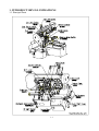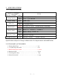
1
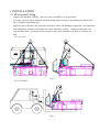
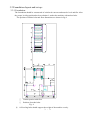
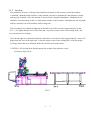
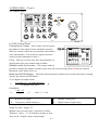
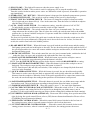
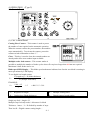
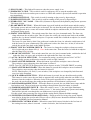
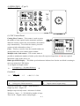
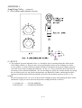
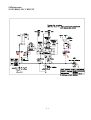
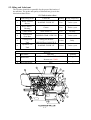
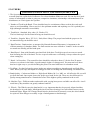
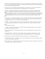
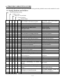
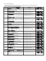
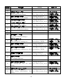
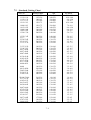
Automatic BANDSAWS
H-330A
FULL STROKE
INSTRUCTION MANUAL
MEGA MACHINE CO., LTD.
DOC NO:
H330A-FULL-100.U
CTRL NO: 06
UPDATE:
2007/9/13
DOC VER: A1
FOREWORD
We hope that the owner of this automatic circular sawing machine will
have years of trouble-free service. The machine has been built
to the highest standards to enable fast accurate cutting to be obtained.
In order that the best results can be achieved from your MEGA circular sawing
Machine, we would ask all operators and maintenance engineers to READ
THIS MANUAL CAREFULLY BEFORE STARTING THE MACHINE.
The manual contains full instructions on installation, operation, lubrication,
maintenance and trouble-shooting.
As MEGA MACHINE COMPANY LIMITED is constantly improving the
design of its machines, there may be some instance where this book differs
somewhat from the machine with which you are concerned. So, always
quote the Serial Number of your machine, when ordering spare parts
or in correspondence relating to the machine.
MODEL : H330A
Serial Number :
Request for service and spare parts should be made to :
ADDRESS: NO. 180, INDUSTRIAL ROAD, TAI-PING CITY,
41107 TAICHUNG, TAIWAN R. O. C.
E-MAIL: [email protected]; [email protected]
URL: www.bandsaw.com.tw
TEL: 886 4 22712877(PRES.) FAX:886 4 22715016
TABLE OF CONTENTS
1. Introductory Illustrations
1.1 Principal parts ---------------------------------------------------------------------------- 1-1
2. Specifications
2.1 Specifications ----------------------------------------------------------------------------- 2-1
3. Installation
3.1 moving and lifting ---------------------------------------------------------------------- 3-1
3.2 Foundation layout and Set-up --------------------------------------------------------- 3-2
4. Operation
4.1 Control Panel ---------------------------------------------------------------------------- 4-1
4.2 Operating preparation ------------------------------------------------------------------ 4-3
4.3 Manual Operation ---------------------------------------------------------------------- 4-4
4.4 Automatic operation -------------------------------------------------------------------- 4-5
4.5 Special Operation ----------------------------------------------------------------------- 4-5
4.6 Break -In Operation -------------------------------------------------------------------- 4-5
Addition 1 Amplifying Valve (Optional) -------------------------------------------------4-6
5. Maintenance
5.1 Hydraulic Circuit ------------------------------------------------------------------------ 5-1
5.2 Oiling and Lubrication ------------------------------------------------------------------ 5-2
5.3 Others ------------------------------------------------------------------------------------- 5-3
6. Trouble Shooting Guide
6.1 Sawing Problems and Solution --------------------------------------------------------- 6-1
6.2 Minor Operating Troubles and Remedies --------------------------------------------- 6-2
6.3 Error information ------------------------------------------------------------------------ 6-3
7. Reference Charts
7.1 Standard cutting Chart
----------------------------------------------------------------- 7-1
7.2 Standard cutting Chart
7.3 Standard cutting Chart
----------------------------------------------------------------- 7-2
----------------------------------------------------------------- 7-3
Addition 2 Electrical Circuit -----------------------------------------------------------------
1. INTRODUCTORY ILLUSTRATIONS
1.1 Principal Parts
1-1
2 SPECIFICATIONS
2.1 SPECIFICATIONS
MODEL
SPECIFICATIONS
Cutting Capacity
Bundle Cutting
Blade Size
Blade Speed
Motor Output
Shipping Volume
Weight Net/Gross
H330A
(Mm)
φ330
□350W*330H
(In)
φ13
□13.7W*13H
(Mm)
264W*150H
(Mm)
32*1.06*3920
(In)
1 1/4*0.042*154.33
(M/Min) 25, 32, 42, 55, 70, 80
(F/Min)
Variable Speed 20-80 M/Min
82, 105, 138, 180, 230, 260
HYD-0.75,
Variable Speed 65-260F/Min
(KW)
Blade-3.75,
(HP)
Blade-5, HYD-1, Coolant- 1/8,
(Mm)
2270*2100*1700
(In)
89.4L*82.7w*66.9H
KG,lb
1450 KG / 1850 lb.
Coolant-0.1
3190 KG / 4070 lb.
Specifications subject to change without notice for improvement and modification.
2.2 STANDARD ACCESSORIES
1. Tools with tool box .............………….……..……....... 1 set
2. 7 ft.(2M) long roller table ...…………………..…......... 1 set
3. Band-cleaning wire brush ...…………………..….......... 1 pieces
4. Band saw blade .................…………………..……....... 1 piece
5. Vertical guide rollers .............………………..……….... 1 set
6. Instruction manual .............………………….……........ 1 copy
2
-
1
3. INSTALLATION :
3.1 Moving and Lifting :
Unpack your machine carefully , and use a crane or forklift to set it in position.
If a crane is used to lift the machine attach the lifting cable carefully to the machine as shown in the
fig 2. If forklift is used then fig 3.
Sufficient space should be left around the machine to allow safe handling of materials , and inspection
and maintenance operation. Should there be other machinery causing vibration or dust that near
your machine, then precautions must be taken to keep your machine away from of vibration and
dust.
(1) Use Crane :
Fig 2
(2) Use Forklift :
Fig 3
3 - 1
3.2 Foundation layout and set-up :
3.2.1 Foundation :
The foundation should be constructed of reinforced concrete and must be level and flat. After
the proper leveling position has been obtained , anchor the machine with anchor bolts.
The position of anchor bolts and floor dimensions are shown in fig 4:
□
○
Contact portion with floor
Position of anchor bolts
Fig. 4
※ All leveling bolts should support the weight of the machine evenly .
3
-
2
3.2.2 Leveling :
The production accuracy of all precision machinery depends on the accuracy which the machine
is installed . Manufacturing tolerance of the machine can only be guaranteed if the machine is firmly
and properly installed . Once the machine is lowered on the prepared foundation . Machinist levels
should be used alternately on the vice slide plates and the work feed table , and adjust the left-and-right
and fore-and-aft level of the machine with leveling bolt .
The fore-and-aft level should be adjusted so that the level of the rear end is approximately 10 mm
(3/8" - 1/2") higher than the level of the front end , to provide proper return of the cutting fluid , and
easy operation of car feeding .
The left-and-right level should be adjusted so that the level of the left end is approximately 3 mm (1/8")
higher than the level of the right end , to provide proper return of the cutting fluid , After the proper
leveling position has been obtained anchor the machine with anchor bolts .
CAUTION : All leveling bolts should support the weight of the machine evenly .
Leveling as fig 5 below :
FIG 5
3
-
3
3.2.3 Cleaning and oiling :
After the machine has been placed in position , thoroughly remove its rust preventive coating using a
suitable cleaning solvent and then apply a coat of machine oil . To clean the machine , Kerosene is
preferable to gasoline . It does not evaperate and level dried slushy compound on finished surfaces.
Rags are better than waste as they leave no lint or strings. The machine as received by you. has been
completely drained of all oil. Before any attempt is made to run it .... Before any motor connections
are made .... every detail of the following oiling instruction must be complied with. Refer to the oiling
chart in chapter 7.
Especially, don't forget to fill up the cutting fluid mixture.
Usually, the ratio of cutting fluid to water should be 1:30 - 1:50. Check the sight gauge to ascertain the
fluid level in the tank every day.
Transmission gear box, bar feed gear box, hydraulic oil tank should to topped up monthly. Oil levels
should be strictly observed, for it is of primary importance for proper operation and long lift .
3.2.4 Power Source Connection :
A. Power Source - This machine is equipped with 5HP main motor and 1HP hydraulic motor , and
1/8HP coolant motor. Connect the power supply cable to the circuit breaker(N.F.B.) terminals.
The power supply to your machine should agree with the wiring voltage that is indicated on the
label attached to the electrical enclosure and main motor.
B. Earth - Be sure to connect the earth cable to the earth terminal.
C. Starting - After making the necessary wiring connections, turn the power switch on the control
Panel clockwise to turn power on, depress the vice limit switch (if necessary, e.g. if there is no stock
bar clamped in the vice) and push the button to see if the saw head moves upward. If the saw head
does not rise , the hydraulic pump motor is rotating in the wrong direction. If the motor runs in the
wrong direction, turn off the power switch and disconnect the power supply cable, Then interchange
any two phase connections.
3
-
4
4. OPERATION (Type 1)
4.1 Control Panel
(1) PNC Control Panel
Cutting Piece Counter – This counter is used to preset
the number of cuts required on the automatic operation.
When the counter reaches the preset number, the machine
stops automatically . To activate the counter, preset the
counter switch with number at least “1”.
Clear – This key is used to clear the counted number cut
already and to have new number input available.
Multiple stroke feed counter – This counter makes it
possible to multiply the number of index cycles when off-cut pieces longer than 400mm are required.
Maximum 9-time stroke can be set.
Blade speed LED-Display -- This blade speed tachometer indicates how fast the saw blade is running
in meter per minute by LED display.
To see digital cut length counter
L (length req.) + K (blade thickness)
S=
-K
N (multiple feed times)
EXAMPLE:
1200 +1.5
S=
-1.5
= 400.5-1.5 = 399
3
L = Required cut length
K = Cutting loss ( Blade thickness )
N = Multiple feeding times
S = Digital counter length setting
Total bar feed needed = length + blade thickness
Single step feed = length + K
Multiple step feed only needs 1 allowance for blade
Thickness ...hence…L + K divided by number of steps
Then less K = Digital counter setting length….
4-1
(2) PILOT LAMP -- This light will comes on when the power supply is on.
(3) EMERGENCY STOP -- This switch is used for emergency case to stop the machine only.
Turn this switch clockwise makes power source on. When this switch is pressed, all machine's operation
stop immediately.
(4) HYDRAULIC "ON" BUTTON -- When this button is depressed, the hydraulic pump motor operates.
(5) POWER SWITCH OFF -- This switch is used for turning off the power by depressing it.
(6) FRONT VISE TO CONFIRM SWITCH – The front vise clamp the workpiece when turn switch
NO.(8) right and press button NO.(6) 1.5sec in the same time. Then the front vise hold the workpiece
after the lamp NO.(6A) light.
(7) AUTO - MANUAL SELECTOR -- For continuous cutting , turn this selector to left "AUTO".
To individually operate each function, turn this switch to right "manual".
(8) FRONT VISE SWITCH -- The switch control the front vise jaws in manual mode, The front vise
clamp when turn the switch to right. Then if release the switch, the switch come back to the middle
position, the vise doesn’t hold the workpiece. If operator would like to hold the workpiece, he would
follow the (6) illustration.
The front vise open little by little if the guide arm is under the front vise when the switch turn to left.
And the front vise open continuously if the guide arm is above the front vise. At last, if release the
switch, the switch come back to the middle position.
(9) BLADE DRIVE BUTTON -- When this button is pressed, both the saw blade motor and the cutting
fluid pump operate and saw head begins to descend. The saw head descends quickly until the feeler of
the quick approach device comes into contact with the workpiece and thereafter, it will descend at the
designated cutting speed.
(10) REAR VISE SWITCH -- This switch control the rear vise jaws in manual mode, switched to the left
makes the front vise open. and switched to the right makes the front vise clamp.
(11) MANUAL FEED FORWARD BUTTON --When this button is pressed the workpiece moves
forward. The workpiece stops advancing when the button is released.
NOTE: Turn (8) VISE SWITCH right position before depress switch (9) BLADE DRIVE to cutting.
(12) MANUAL FEED BACKWARD BUTTON --When this button is pressed the workpiece moves
backward. The workpiece stops moving when the button is released.
NOTE: Don't depress (11) and (12) two switches, if the workpiece are clamped by both front and
rear vises in the meantime.
(13) QUICK APPROACH BUTTON -- While this button is pressed, the saw head descends quickly.
This button is used to cause the saw blade to approach the work quickly when the saw blade is at a
distance from the workpiece. When the feeler of the quick approach device comes into contact with
the work, the saw head stops descending at that position even this button is still pressed.
(14) SAW FRAME RAISE BUTTON -- When this button is pressed, the saw blade motor stops and the
saw head ascends. The saw head stops ascending at that position when the button is released.
(15) WORK BEAM LIGHT SWITCH -- When this switch is set at "1" the work light illuminates.
(16) AUTO CHIP CONVEYOR & COOLANT SWITCH -- When this switch is set at "1" the cutting
fluid pump operates and cutting fluid will be injected even though the saw blade motor is not in
operation. Use this switch when removing saw chips with the cutting fluid (without the blade running).
(17). INVERTER CONTROL KNOB (OPTIONAL)-- Please turn left for being slow speed wanted, turn
right for being fast speed wanted. Please refer to (JPS) Inverter Instruction Manual or Please refer to
(TOSHIBA) Inverter Instruction Manual
(18) FEED RATE CONTROL KNOB -- When this control dial is turned clockwise the feed rate of
the cutting increases, when it is turned counter clockwise, the feed rate decreases.
(19) CUTTING PRESSURE CONTROL KNOB -- When this control dial is turned clockwise the
cutting pressure increases, when it is turned count clockwise, the cutting pressure decreases.
4–2
4. OPERATION (Type 2)
4.1 Control Panel
(1) PNC Control Panel
Cutting Piece Counter – This counter is used to preset
the number of cuts required on the automatic operation.
When the counter reaches the preset number, the machine
stops automatically . To activate the counter, preset the
counter switch with number at least “1”.
Clear – This key is used to clear the counted number cut
already and to have new number input available.
Multiple stroke feed counter – This counter makes it
possible to multiply the number of index cycles when off-cut pieces longer than 400mm are required.
Maximum 9-time stroke can be set.
Blade speed LED-Display -- This blade speed tachometer indicates how fast the saw blade is running in
meter per minute by LED display.
To see digital cut length counter
L (length req.) + K (blade thickness)
S=
-K
N (multiple feed times)
EXAMPLE:
1200 +1.5
S=
-1.5
= 400.5-1.5 = 399
3
L = Required cut length
K = Cutting loss ( Blade thickness )
N = Multiple feeding times
S = Digital counter length setting
Total bar feed needed = length + blade thickness
Single step feed = length + K
Multiple step feed only needs 1 allowance for blade
Thickness ...hence…L + K divided by number of steps
Then less K = Digital counter setting length….
4-1
(2) PILOT LAMP -- This light will comes on when the power supply is on.
(3) EMERGENCY STOP -- This switch is used for emergency case to stop the machine only.
Turn this switch clockwise makes power source on. When this switch is pressed, all machine's operation
stop immediately.
(4) POWER SWITCH ON -- This switch is used for turning on the power by depressing it.
(5) POWER SWITCH OFF -- This switch is used for turning off the power by depressing it.
(6) HYDRAULIC "ON" LAMP -- When NO.(4) button is depressed, the hydraulic pump motor operates.
This lamp is light.
(7) BLADE DRIVE BUTTON -- When this button is pressed, both the saw blade motor and the cutting
fluid pump operate and saw head begins to descend. The saw head descends quickly until the feeler of
the quick approach device comes into contact with the workpiece and thereafter, it will descend at the
designated cutting speed.
(8) FRONT VISE SWITCH -- The switch control the front vise jaws in manual mode, The front vise
clamp when turn the switch to right. Then if release the switch, the switch come back to the middle
position, the vise doesn’t hold the workpiece. If operator would like to hold the workpiece, he would
follow the (9) illustration.
The front vise open little by little if the guide arm is under the front vise when the switch turn to left.
And the front vise open continuously if the guide arm is above the front vise. At last, if release the
switch, the switch come back to the middle position.
(9) FRONT VISE TO CONFIRM SWITCH – The front vise clamp the workpiece when turn switch
NO.(8) right and press button NO.(9) 1.5sec in the same time. Then the front vise hold the workpiece
after the lamp NO.(9A) light.
(10) REAR VISE SWITCH -- This switch control the rear vise jaws in manual mode, switched to the left
makes the front vise open. and switched to the right makes the front vise clamp.
(11) AUTO - MANUAL SELECTOR -- For continuous cutting , turn this selector to left "AUTO".
To individually operate each function, turn this switch to right "manual".
(12) MANUAL FEED FORWARD --When this button is pressed the workpiece moves forward.
The workpiece stops advancing when the button is released.
NOTE: Turn (8) VISE SWITCH right position before depress switch (7) BLADE DRIVE to cutting.
(13) MANUAL FEED BACKWARD --When this button is pressed the workpiece moves backward.
The workpiece stops moving when the button is released.
NOTE: Don't depress (12) and (13) two switches, if the workpiece are clamped by both front and
rear vises in the meantime.
(14) QUICK APPROACH BUTTON -- While this button is pressed, the saw head descends quickly.
This button is used to cause the saw blade to approach the work quickly when the saw blade is at a
distance from the workpiece. When the feeler of the quick approach device comes into contact with
the work, the saw head stops descending at that position even this button is still pressed.
(15) SAW FRAME RAISE BUTTON -- When this button is pressed, the saw blade motor stops and the
saw head ascends. The saw head stops ascending at that position when the button is released.
(16) WORK BEAM LIGHT SWITCH -- When this switch is set at "1" the work light illuminates.
(17) COOLANT SWITCH -- When this switch is set at "1" the cutting fluid pump operates and cutting
fluid will be injected even though the saw blade motor is not in operation.
Use this switch when removing saw chips with the cutting fluid (without the blade running).
(18) INVERTER CONTROL KNOB (OPTIONAL)-- Please turn left for being slow speed wanted,
turn right for being fast speed wanted. Please refer to (JPS) Inverter Instruction Manual or Please
refer to (TOSHIBA) Inverter Instruction Manual
(19) FEED RATE CONTROL KNOB -- When this control dial is turned clockwise the feed rate of
the cutting increases, when it is turned counter clockwise, the feed rate decreases.
4
-2
4. OPERATION (Type 3)
4.1 Control Panel
(1) PNC Control Panel
Cutting Piece Counter – This counter is used to preset
the number of cuts required on the automatic operation.
When the counter reaches the preset number, the machine
stops automatically . To activate the counter, preset the
counter switch with number at least “1”.
Clear – This key is used to clear the counted number cut
already and to have new number input available.
Multiple stroke feed counter – This counter makes it
possible to multiply the number of index cycles when off-cut pieces longer than 400mm are required.
Maximum 9-time stroke can be set.
Blade speed LED-Display -- This blade speed tachometer indicates how fast the saw blade is running in
meter per minute by LED display.
To see digital cut length counter
L (length req.) + K (blade thickness)
S=
-K
N (multiple feed times)
EXAMPLE:
1200 +1.5
S=
-1.5
= 400.5-1.5 = 399
3
L = Required cut length
K = Cutting loss ( Blade thickness )
N = Multiple feeding times
S = Digital counter length setting
Total bar feed needed = length + blade thickness
Single step feed = length + K
Multiple step feed only needs 1 allowance for blade
Thickness ...hence…L + K divided by number of steps
Then less K = Digital counter setting length….
4-1
(2) PILOT LAMP -- This light will comes on when the power supply is on.
(3) EMERGENCY STOP -- This switch is used for emergency case to stop the machine only.
Turn this switch clockwise makes power source on. When this switch is pressed, all machine's
operation stop immediately.
(4) HYDRAULIC "ON" BUTTON -- When this button is depressed, the hydraulic pump motor operates.
(5) POWER SWITCH OFF -- This switch is used for turning off the power by depressing it.
(6) FRONT VISE TO CONFIRM SWITCH – The front vise clamp the workpiece when turn switch
NO.(8) right and press button NO.(6) 1.5sec in the same time. Then the front vise hold the workpiece
after the lamp NO.(6A) light.
(7) AUTO - MANUAL SELECTOR -- For continuous cutting , turn this selector to left "AUTO".
To individually operate each function, turn this switch to right "manual".
(8) FRONT VISE SWITCH -- The switch control the front vise jaws in manual mode, The front vise
clamp when turn the switch to right. Then if release the switch, the switch come back to the middle
position, the vise doesn’t hold the workpiece. If operator would like to hold the workpiece, he would
follow the (6) illustration.
The front vise open little by little if the guide arm is under the front vise when the switch turn to left.
And the front vise open continuously if the guide arm is above the front vise. At last, if release the
switch, the switch come back to the middle position.
(9) BLADE DRIVE BUTTON -- When this button is pressed, both the saw blade motor and the cutting
fluid pump operate and saw head begins to descend. The saw head descends quickly until the feeler of
the quick approach device comes into contact with the workpiece and thereafter, it will descend at the
designated cutting speed.
(10) REAR VISE SWITCH -- This switch control the rear vise jaws in manual mode, switched to the left
makes the front vise open. and switched to the right makes the front vise clamp.
(11) MANUAL FEED FORWARD BUTTON --When this button is pressed the workpiece moves
forward. The workpiece stops advancing when the button is released.
NOTE: Turn (8) VISE SWITCH right position before depress switch (9) BLADE DRIVE to cutting.
(12) MANUAL FEED BACKWARD BUTTON --When this button is pressed the workpiece moves
backward. The workpiece stops moving when the button is released.
NOTE: Don't depress (11) and (12) two switches, if the workpiece are clamped by both front and
rear vises in the meantime.
(13) QUICK APPROACH BUTTON -- While this button is pressed, the saw head descends quickly.
This button is used to cause the saw blade to approach the work quickly when the saw blade is at a
distance from the workpiece. When the feeler of the quick approach device comes into contact with
the work, the saw head stops descending at that position even this button is still pressed.
(14) SAW FRAME RAISE BUTTON -- When this button is pressed, the saw blade motor stops and the
saw head ascends. The saw head stops ascending at that position when the button is released.
(15) WORK BEAM LIGHT SWITCH -- When this switch is set at "1" the work light illuminates.
(16) AUTO CHIP CONVEYOR & COOLANT SWITCH -- When this switch is set at "1" the cutting
fluid pump operates and cutting fluid will be injected even though the saw blade motor is not in
operation. Use this switch when removing saw chips with the cutting fluid (without the blade running).
(17). INVERTER CONTROL KNOB (OPTIONAL)-- Please turn left for being slow speed wanted, turn
right for being fast speed wanted. Please refer to (JPS) Inverter Instruction Manual or Please refer to
(TOSHIBA) Inverter Instruction Manual
(18) FEED RATE CONTROL KNOB -- When this control dial is turned clockwise the feed rate of
the cutting increases, when it is turned counter clockwise, the feed rate decreases.
4–2
4. OPERATION (Type 4)
4.1 Control Panel
(1) PNC Control Panel
Cutting Piece Counter – This counter is used to preset
the number of cuts required on the automatic operation.
When the counter reaches the preset number, the machine
stops automatically . To activate the counter, preset the
counter switch with number at least “1”.
Clear – This key is used to clear the counted number cut
already and to have new number input available.
Multiple stroke feed counter – This counter makes it
possible to multiply the number of index cycles when off-cut pieces longer than 500mm are required.
Maximum 9-time stroke can be set.
Blade speed LED-Display -- This blade speed tachometer indicates how fast the saw blade is running in
meter per minute by LED display.
To see digital cut length counter
L (length req.) + K (blade thickness)
S=
-K
N (multiple feed times)
EXAMPLE:
1200 +1.5
S=
-1.5
= 400.5-1.5 = 399
3
L = Required cut length
K = Cutting loss ( Blade thickness )
N = Multiple feeding times
S = Digital counter length setting
Total bar feed needed = length + blade thickness
Single step feed = length + K
Multiple step feed only needs 1 allowance for blade
Thickness ...hence…L + K divided by number of steps
Then less K = Digital counter setting length….
4-1
(2) PILOT LAMP -- This light will comes on when the power supply is on.
(3) EMERGENCY STOP -- This switch is used for emergency case to stop the machine only.
Turn this switch clockwise makes power source on. When this switch is pressed, all machine's operation
stop immediately.
(4) HYDRAULIC "ON" BUTTON -- When this button is depressed, the hydraulic pump motor operates.
(5) POWER SWITCH OFF -- This switch is used for turning off the power by depressing it.
(6) FRONT VISE TO CONFIRM SWITCH – The front vise clamp the workpiece when turn switch
NO.(8) right and press button NO.(6) 1.5sec in the same time. Then the front vise hold the workpiece
after the lamp NO.(6A) light.
(7) AUTO - MANUAL SELECTOR -- For continuous cutting , turn this selector to left "AUTO".
To individually operate each function, turn this switch to right "manual".
(8) FRONT VISE SWITCH -- The switch control the front vise jaws in manual mode, The front vise
clamp when turn the switch to right. Then if release the switch, the switch come back to the middle
position, the vise doesn’t hold the workpiece. If operator would like to hold the workpiece, he would
follow the (6) illustration.
The front vise open little by little if the guide arm is under the front vise when the switch turn to left.
And the front vise open continuously if the guide arm is above the front vise. At last, if release the
switch, the switch come back to the middle position.
(9) BLADE DRIVE BUTTON -- When this button is pressed, both the saw blade motor and the cutting
fluid pump operate and saw head begins to descend. The saw head descends quickly until the feeler of
the quick approach device comes into contact with the workpiece and thereafter, it will descend at the
designated cutting speed.
(10) REAR VISE SWITCH -- This switch control the rear vise jaws in manual mode, switched to the left
makes the front vise open. and switched to the right makes the front vise clamp.
(11) MANUAL FEED FORWARD BUTTON --When this button is pressed the workpiece moves
forward. The workpiece stops advancing when the button is released.
NOTE: Turn (8) VISE SWITCH right position before depress switch (9) BLADE DRIVE to cutting.
(12) MANUAL FEED BACKWARD BUTTON --When this button is pressed the workpiece moves
backward. The workpiece stops moving when the button is released.
NOTE: Don't depress (11) and (12) two switches, if the workpiece are clamped by both front and
rear vises in the meantime.
(13) QUICK APPROACH BUTTON -- While this button is pressed, the saw head descends quickly.
This button is used to cause the saw blade to approach the work quickly when the saw blade is at a
distance from the workpiece. When the feeler of the quick approach device comes into contact with
the work, the saw head stops descending at that position even this button is still pressed.
(14) SAW FRAME RAISE BUTTON -- When this button is pressed, the saw blade motor stops and the
saw head ascends. The saw head stops ascending at that position when the button is released.
(15) WORK BEAM LIGHT SWITCH -- When this switch is set at "1" the work light illuminates.
(16) AUTO CHIP CONVEYOR & COOLANT SWITCH -- When this switch is set at "1" the cutting
fluid pump operates and cutting fluid will be injected even though the saw blade motor is not in
operation. Use this switch when removing saw chips with the cutting fluid (without the blade running).
(17) FEED RATE CONTROL -- When the control dial is turned counter clockwise, the feed rate of the
saw blade increases, when it is turned clockwise, the feed rate depresses.
4 -2
4.2 OPERATING PREPARATION
There are several steps will be taken before start the machine.
(1) CHOOSE PROPER SAW BLADE :
Select the saw blade best suited to the workpiece to be cut, Size and shape of the workpiece , and
type of material should all be sonsidered when selecting the saw blade to be used . There is a refernce
chart in chapter 9 which can help you to select the right saw blade and cutting conditions .
(2) UNPACK THE SAW BLADE :
Usually the saw blade is packed in 3 circle ,unpack it one circle first grip the part to release another 2
circles gradually , tear off the saw-cap protective shield , inspect the blade teeth , make sure that the
cutting edge of the blade teeth point to the right . If they point to the left the blade should be turned over.
(3) PLACE THE SAW BLADE ONTO BOTH THE DRIVE AND DRIVEN WHEELS ---a. Turn the hydraulic blade tension handle clockwise , to fully loosen the driven wheel .
b. Open both the drive and driven wheel covers , place the saw blade onto both the drive and driven
wheels. Check the cutting edge of the saw blade , to ensure that it point to the right.
c. Insert the saw blade into both the left and right blade guides so that the back edge of the saw blade
touches the back-up roller of each guide .
d. The back edge of the saw blade should make contact with the flange of the drive and driven wheel ,
turn count -clockwise the hydraulic blade tension handle to tighten
the saw blade , Then the blade
is properly tensioned .
e. Don't forget to tighten the insert adjusting screw .
(4) WORKPIECE CLAMPING :
a. Raise the saw frame , open the vise , place the workpiece on the roller table .
b. Gently push the workpiece into the roller-feed vise, taking care not hit the feed rollers.
c. Clamp the workpiece in vise.
(5) ADJUST THE BLADE GUIDE ARM :
Properly position the blade guide arms according to the diameter (or the width) of the workpiece to be cut.
a. loosen the insert adjusting screw.
b. loosen the lock lever of the blade guide arm, and manually move the blade guide arm to suit the width of
material using the scale provided.
c. After adjusting the blade guide arm position ,tighten the lock lever.
d. Finger tighten the insert adjusting screw.
(6) ADJUST THE POSITION OF THE WIRE BRUSH :
a. loosen the lock lever of the wire brush case.
b. Manually move the wire brush case so that wire brush just contacts the cutting edge of the saw blade.
c. Tighten the lock lever.
4–3
(7) ADJUST THE FEED RATE :
Select suitable feed rate for the workpiece to be cut. This varies according to the size and shape of the
workpiece, type of material , and what type of saw blade is being used. As a guide hard materias, wide
workpiece or structural sections and tubing have to be cut at a slower rate that mild steel bar.
As concerns the saw blade , bigh speed steel is better than carbon steel, and bi-metal alloy is better than
high speed steel. Roughly the ratio of feed speeds could be 1:2:3
(8) CUTTING LENGTH PRESET :
To preset the length of the workpiece to be cut ,use the precise cutting piece counter which is at front
leftside of the machine.
a. Turn the handle wheel and watch the counter to the length you want to cut. The calibration is 0.10
mm.for example: 400.1 mm
b. Tighten the lock screw.
(9) SELECT THE SAW BLADE SPEED :
There are 6 speeds provided : 25, 32, 42, 55, 70, 80 M/min
If a optional variable speed drive is equipped the speed to be 20 to 80 M/Min steplessly.
4.3 MANUAL OPERATION :
Place the workpiece to be cut on the work table , decide how long you want the off-cut , and carry
out all the procedures as described above in [4.2] Operating Preparation.
(1) Depress the RAISE button to lift the saw frame until the cutting edge of the saw blade clears the
workpiece by 1/2 to 3/4 inch.
(2) Turn the AUTO-MANUAL selector to manual.
(3) Adjust the spacing of the blade guide arms.
(4) Preset the required cutting length of the workpiece.
(5) In control panel – The front vise clamp the workpiece when turn switch NO.(8) right and press
button NO.(6) 1.5sec in the same time. Then the front vise hold the workpiece after the lamp
NO.(6A) light.
(6) Confirm the procedure (5),then clamp the workpiece.
(7) Adjust the FEED RATE.
(8) Confirm to clamp the workpiece in procedure (5), then dpress BLADE DRIVE button to start both
the saw blade motor and the cutting fluid pump and the saw frame begins to descend.
(9) After completion of the cut saw blade stops at the lower limit position.
(10) Depress the RAISE button to cut next piece again.
*. Before you start to cut the workpiece, you must inspect that....
a. The workpiece is well clamped.
b. The saw blade is suitable for the material being cut.
c. The feed rate is suitable for the material being cut.
d. The speed of the saw blade is suitable for the material being cut.
e. The insert adjusting screw and the lock lovers of the blade guide arms are all tightened.
f. Sufficient tension is placed on the saw blade.
g. The wire brush is properly positioned.
h. There is sufficient cutting fluid in good condition.
i. The off-cut length is as required.
4–4
4.4 AUTOMATIC OPERATION :
Having finished all the procedures described above in (2) Operating Preparation ,and with the
workpiece to be cut placed in the vise of the machine , but NOT under the saw blade.
(1) Turn the AUTO-MANUAL selector to manual. In control panel – The front vise clamp the
workpiece when turn switch NO.(8) right and press button NO.(6) 1.5sec in the same
time. Then the front vise hold the workpiece after the lamp NO.(6A) light.
(2) Turn the AUTO-MANUAL selector to auto.
(3) Depress the QUICK APPROACH switch to make the saw frame descend quickly to touch the lower
limit position , it will then rise automatically to the freight preset.
(4) Preset the number of cuts required.
(5) Confirm to clamp the workpiece in procedure (1) and (2).
(6) Depress the BLADE DRIVE button to start both the saw blade motor and the cutting fluid pump.
The saw frame begins to descend to cut workpiece.
(7) After the required number of cut has been completed, the saw frame will lift to the raised position
and all machine operation will stop.
(8) The machine will automatically stop, when the workpiece is so short that it can no longer be
automatically feed.
4.5 SPECIAL OPERATION :
(1) While you are cutting a workpiece, if the saw blade suddenly jams in the workpiece, depress the
FRAME RAISE button to lift the saw frame immediately.
(2) The saw blade jamming in the workpiece is most likely because of :
a. Slippage occurring between saw blade and drive wheel. Tension placed on the saw blade is not
sufficient.
b. Slippage occurring between drive belt and motor pulley. Tension on drive belt is not sufficient or
belt is worn.
c. Broken teeth on saw blade.
d. Too blunt saw blade.
e. Too fine tooth spacing on saw blade for material being cut.
f. Too fast feed rate for material being cut and blade used.
4.6 BREAK-IN OPERATION:
When a new blade is used , be sure to first break in the blade before using it for extended operation.
Failure to break in the blade will shorten the service lift of the blade ,and result in less than optimum
efficiency. To break in the blade ,proceed as follow :
(1) Reduce the blade speed setting to one half of its normal setting .
(2) Lengthen the time required for cutting to 2-3 times that of normal.
(3) The break-in operation can be considered sufficient if all unusual noises or metallic sounds have
been eliminated. (For instance, to completely break in the blade, a minimum of five complete cuts
of a 200mm (8 ins) diameter work- piece will be required.)
(4) After the break-in operation has been completed, return the blade speed and feed rate to their
normal setting.
4–5
ADDITION 1:
Amplifying Valve
( Optional )
(1.) The outlines and hydraulic circuits:
(2.) SET-UP
A. The hydraulic pressure indicated in line <p> should be kept in constant during the whole stroke
of the lifting cylinder, i.e. Between the very top and bottom position of the swinging saw frame.
we use springs <r> inside of lifting cylinder to balance/compensate the pressure changes (pressure
varies due to saw frame swinging up and down ) in line <p>. above procedures have been done in
our factory before machine dispatched , now for checking test, please dry run the machine by raising
the saw frame to the very top position and push the saw blade drive button, and having the quick
approach rod lifted (limit switch un-touched), then check the hydraulic pressure in line <p> by
reading
the pressure gauge at line <p> to see if the pressure readings keep the same during the whole stroke.
(maximum 1 kg/sq.cm varies allowed) the pressure reading should be as follows:
8 KG/SQ.CM ............250/300 MODELS
10 KG/SQ.CM ............360/400/450 MODELS
4–6
B. Re-zeroing knob "a" & "b" on the amplifying valve:
For zeroing knob "a", there is a hydraulic pressure gauge as drawing <S> needed, Please plug it
onto the outlet on the amplifying valve.
Pressure read at line <p> as the primary pressure............pressure <p>
Pressure read at amplifying valve as the secondary pressure.. pressure <s>
The primary pressure should be kept the same reading, and the secondary pressure can be adjusted
by turning knob "b" for cutting pressure settings zeroing knob "a" :
-----------------Dry run the machine as stated in above paragraph,
Turn knob "b" while reading pressure <s>, If there is any pressure can be read, then turn knob "a"
While watching saw frame, if the saw frame shall stand still there without coming down, then there is
the zero position of the knob "a" ( zero feed-rate ), check the " △ " mark on the knob "a" to see if
this mark pointing to "0" position. If not, loosen set screw and zeroing it ( Please make sure tighten
the set screw after zeroing ). zeroing knob "b" :
-----------------After zeroing knob "a", turn knob "a" at "5" position, and let the machine running in the same
condition as previous did - dry running. turn knob "b" while reading pressure <s>, If the pressure
reach 5.5 to 6 kg /sq.cm, then loosen the set screw on the knob "b" and have the " △"
mark
pointing to "5" position and tighten the set screw.
(3.) OPERATION
Knob "a" is for maximum feed-rate setting:
The smaller the diameter of the material being cut, the higher feed-rate.
The softer the material being cut, the higher feed-rate can be set. And vice-versa.
Knob "b" is for cutting pressure setting:
The tougher the material being cut, the hiher cutting pressure needed. For instance, when cutting
thin pipes/tubes, mild carbon steels, Only little pressure needed, and for stainless/high alloy tool
steels or inconel special steels, high cutting pressure should be needed. There are both AISI/JIS
material codes shown on the control panel, Please refer to it for proper cutting pressure setting.
LIMITATION: The sum of the number set on knob "a" and "b" can not exceed 10.
4–
7
5.Maintenance
5.1 HYDRAULIC CIRCUIT
5-1
5.2 Oiling and Lubricant
The operator should be responsible for the proper lubrication of
the machine. The grade and quality of lubricant are given in the
lubrication chart below :
Oil Lubrication chart
Lubricating Point
Lubricant
Quantity Oiling Frequency
1.
Blade Tension
Device
DAPHNE FLUID 32T
Few
Twice a year
2.
Drive Wheel
Bearing
Grease
Few
Thrice a year
3.
Guide Slides
Shell Tonna 33
Few
Oil daily
4.
Transmission
Gear Box
DAPHNE GEAR LUBE 320
Few
Twice a year
5.
Cutting Fluid
Tank
Cutting Oil Mixture
(KH ULTRA COOL EX-2)
82 liter
Daily
6.
Hydraulic Oil
Tank
DAPHNE FLUID 32T
44 liter
Twice a year
Belt Size
Belt Name
7
Motor Belt
8
Wire Brush Belt
Belt Size
50HZ use 3V475 & 60HZ use 3V450
Inverter use 3V450
Quantity
M42
1
5-2
1
5.3 OTHERS
VARIABLES WHICH AFFECT BANDSAW BLADE LIFE
1. The Operator - The operator is the most important variable at any test. He can make or break any
test and often has a qreat deal of influence over whose bandsaw blades are used. He can also be a good
source of information on what is going on, competitive situations, relationships with manufacturers or
distributors, etc. Don't ignore the operator.
2 . Number of Teeth in the Band - There should always be a minimum of three teeth in the work at all
times to avoid straddling. Nine to twelve is the optimum number and anything over 24 is probably too
high (although sometimes unavoidable).
3 . Tooth Style - Standard, skip, sabre, Si -Pitch or XL.
The best tooth style for the material being cut should be used.
4 . Tooth Set - Regular, Wavy, E.T.S.,Si - Pitch, Maxi -Sharp. The proper band with the proper set for
the material being cut should be used.
5 . Band Tension - Band tension, as measured by Simonds Patented Simometer, is important to the
efficient running of a bandsaw blade. Too little tension can cause a blade to "wander" in the cut while
too much can actually pull the band apart.
6 . Band Speed - Start with Simonde speed and feed slide chart. Too high a speed can cause too much
heat lessening the life of the band. Too low a speed could cause overfeeding. Always reduce the speed
when cutting dry.
7 . Break - in Procedure - The normal feed rate should be reduced to about 1/2 for the first 50 square
inches or so to hone in the blade. A good example is that of a sharp pencil. You must not bear down
hard on it right away or you risk breaking the point. The same holds true for a bandsaw tooth.
8. Feed Rate - Set the feed rate by square inches per minute according to simonds speed and feed slide
chart. Watch your chips and adjust accordingly as both overfeeding and underfeeding cut bandsaw life.
9. Band Quality - Carbon steel blades vs. High Speed Blades, M-2 vs. M42, etc. All affect the life you will
get from the band. Once again choose the proper type band for the job. There are also differences in
quality among manufacturers. Simonds has some of the highest quality standards in the world.
10. Machine Type - Different makes and models with varying horsepower available can affect life. A well
made heavy duty machine can greatly enhance band life.
11. Wheels - The Wheels carry the band and it is very important that they be properly aligned and that
the bearings be in good shape. Misaligned wheels and loose bearings can cause undue stresses on the
band and reduce fatigue life. Flanges should also be checked and if extremely worn, the wheel should
be replaced. Worn flanges are usually a sign of misalignment or bad bearings.
5-3
12. Machine Condition-Whether a machine is old or new, and whether well maintained or not contributes
to how well it runs and how long the band last. The better shape a machine is in, the better the bands will
run. Poor machines ruin bandsaw blades.
13. Proper Vises - The work must be properly held. Side vises and top vises, if necessary, should be in
good shape and able to firmly hold the work. Anything that moves will strip teeth.
14. Guides - The guides must support the band well while in the cut. The guides in conjunction with
tension are all that keeps the band straight. Roller guides should be snug against the band and turn
freely.
The surface should be flat and not worn at an angle. Solid carbide guiles should also be sung against the
band and should show no sign of wear. They can be faced off if necessary. Backup guides should not be
grooved and should also turn freely if rollers. Be sure the teeth of the band do not ride up into the
guides.
15. Guide Arms - The guide arms should be as close to the work as possible. Beam strength is determined
by a cubed factor, so increasing the distance between the guides by a factor of 2 decreases the beam
strength by a factor of (2)^3 or 8. You lose a lot very quickly.
16. Brushes - A good set of brushes (powered is preferable) aid in the cleaning of chips from the gullets,
if available and properly adjusted. One test shows a better than 25﹪increase in life just by using
brushes.
Always check the brushes.
17. Coolant - A good coolant will help cool, lubricate and wash the bandsaw blades. Always maintain a
good flood of coolant when possible.
18. Material machinability - The tougher the material, the less expected band life. For instance 1018 vs.
Inconel 718.
19. Material Hardness - A Rockwell C scale reading of 40 is approaching a machinability of 0. Only
recently have we been able to go much beyond this with the introduction of our CT Type III band.
20. Material Shape - Structurals and small solids are always harder on a band than large solids.
21. Production Requirement - Continuous runs of one size and material is easier than intermittent cutting
of various sizes, shapes and materials.
22. Room Temperature - Temperature has a big effect on the hydraulic system of a machine. Always allow
the machine to warm up before staring to saw.
5–4
6. TROUBLE SHOOTING GUIDE
The following charts contains some typical troubles along with the probable causes and remedies for each.
6.1 Sawing Problems and Solution
Vibration during cutting
Failure to cut
Short life of saw blade
Curved cutting
Broken blade
○
○
○
○
○
○
○
○
○
○
○
○
○
○
○
○
○
○
○
○
○
○
○
○
○
○
○
○
○
○
○
○
○
○
○
○
○
○
○
○
○
○
○
○
○
○
○
○
○
○
○
○
○
○
○
○
○
○
○
○
○
○
○
○
○
○
○
○
○
○
○
○
○
○
○
○
○
○
○
○
○
○
○
○
○
○
○
○
○
○
○
○
○
Use of blade with incorrect pitch
Use blade with correct pitch ,
suited to workpiece
Perform break-in operation
Reduce speed
Increase speed
Reduce feed rate
Increase feed rate
Increase tension
Relocate or replace
Check and correct
Check and correct
Soften material surface
Reduce cutting rate
Replace with suitable workpiece
Add fluid or replace
Relocate machine
Replace
Bleed air
Replace
Replace
Stabilize
Bring blade guide arm close to
workpiece
Tighten
Reduce cutting rate
Clean
Failure to break-in saw blade
Excessive saw blade speed
Insufficient saw blade speed
Excessive load
Insufficient load
Insufficient saw blade tension
Wire brush not working correctly
Blade improperly guided by insert
Improperly clamped workpiece
Excessively hard material surface
Excessive cutting rate
Non-annealed workpiece
Insufficient or lean cutting fluid
Vibration near machine
Non-water soluble cutting fluid used
Air in lift cylinder
Broken back-up roller
Use of non-specified saw blade
Fluctuation of line voltage
Adjustable blade guide arm too far
from workpiece
Loose blade guide
Blue or purple saw chips
Accumulation of chips at inserts
Reverse positioning of blade on
Re-install
machine
Workpiece not bundled properly
Re-bundle
Back edge of blade too hard against
Adjust wheel so that blade is just
flange
firmly against flange
Use other machine, suited for
Workpiece of insufficient dia.
diameter of workpiece
Saw blade teeth worn
Replace
6-1
6.2 Minor Operating Troubles and Remedies
Symptom
1. Buttons do not
function
Probable Cause
Remedy
(1) Power disconnected
(2) Circuit protector OFF
(3) Thermal relay activated
(4) Safety interlocks that is
a. No workpiece is clamped in the vice.
b. The saw frame is not fully raised to
the height preset.
c. The saw frame is raised too high so
that the upper limit switch has been touched
(1) Connect
(2) Turn on
(3)Push reset button
a. Load workpiece
b. Depress FRAME RAISE button
c. Depress QUICK APPROACH
switch
2. The saw frame (1) Solenoid valve blocked.
descends out of (2) Piping leakage
sequence
(3)Packings , O-Rings of cylinder worn or
torn
(1) Disassemble the valve and clean
thoroughly.
(2) Inspect hydraulic piping
(3) Replace
3. Short service
life of wire
brush
(1) Wire brush too heavily in contact with
saw blade.
(1) Re-position the wire brush.
4. Bubbles out of
fluid taps
(1) The cutting fluid is not sufficient
(2) The filter clogged by swarf
(1) fill up take.
(2) Clean the tank and filter.
6-2
6.3. Error information
The following table contains some typical errors along with the error details and remedies.
AH257_ Bandsaws Trouble shooting guide
Error name 異常名稱
Code
00
01
正常停機
按鋸帶上升按鈕
Machine stops normally
上升電磁閥異常
Solenoid - ascending frame abnormal
1.Eliminate breakdown
2.Press Blade-ascending button
1.排除故障原因
2.按鋸帶上升按鈕
1.Eliminate breakdown
Lower limit switch – descending frame 2.Press Blade-ascending button
abnormal
前後限卡死異常
1.Eliminate breakdown
Front/rear limit switch – bar feeding 2.Press Blade-ascending button
1.排除故障原因
2.按鋸帶上升按鈕
下限開關異常
02
03
04
05
06
07
10
11
12
13
14
15
排除方法
Remedy
1.Press Blade-ascending button
saddle abnormal
前進電磁閥異常
1.排除故障原因
2.按鋸帶上升按鈕
1.Eliminate breakdown
2.Press Blade-ascending button
1.排除故障原因
2.按鋸帶上升按鈕
1.Eliminate breakdown
2.Press Blade-ascending button
1.排除故障原因
2.按鋸帶上升按鈕
1.Eliminate breakdown
Saw frame touches fast to lower limit 2.Press Blade-ascending button
switch abnormal
鋸帶近接開關異常
1.Eliminate breakdown
2.Press Blade-ascending button
Sensor – switch abnormal
1.排除故障原因
2.按鋸帶上升按鈕
Solenoid – feeding forward abnormal
無料異常
No material switch abnormal
快速下降碰到下限開關異常
上限開關異常
1.排除故障原因
2.按鋸帶上升按鈕
1.Eliminate breakdown
2.Press Blade-ascending button
1.排除故障原因
2.按鋸帶上升按鈕
1.Eliminate breakdown
2.Press Blade-ascending button
1.排除故障原因
2.按鋸帶上升按鈕
1.Eliminate breakdown
2.Press Blade-ascending button
1.排除故障原因
2.按鋸帶上升按鈕
1.Eliminate breakdown
2.Press Blade-ascending button
1.排除故障原因
2.按鋸帶上升按鈕
1.Eliminate breakdown
2.Press Blade-ascending button
1.排除故障原因
2.按鋸帶上升按鈕
1.Eliminate breakdown
2.Press Blade-ascending button
1.排除故障原因
2.按鋸帶上升按鈕
1.Eliminate breakdown
Hyd. Motor overload or coolant pump 2.Press Blade-ascending button
overload
1.排除故障原因
2.按鋸帶上升按鈕
Upper limit switch abnormal
前極限開關異常
Front limit switch abnormal
後退電磁閥異常
Feed-backward solenoid abnormal
後極限開關異常
Rear limit switch abnormal
變頻器出現異常
Inverter abnormal
變頻器故障
Inverter-breakdown
16
油壓馬達過負載 OR 水泵馬達過負載
17
6-3
異常編號
異常名稱
Remedy
排除方法
20
21
22
23
24
25
26
鋸帶啟動按鈕卡死異常
Starting blade button jammed
鋸帶下降按鈕卡死異常
Descending blade button jammed
送料架前進按鈕卡死異常
Feed-forward button jammed
送料架後退按鈕卡死異常
Feed –forward button jammed
前夾鉗-開 按鈕卡死異常
Front vise opening button jammed
1.Eliminate breakdown
2.Press Blade-ascending button
1.排除故障原因
2.按鋸帶上升按鈕
1.Eliminate breakdown
2.Press Blade-ascending button
1.排除故障原因
2.按鋸帶上升按鈕
1.Eliminate breakdown
2.Press Blade-ascending button
1.排除故障原因
2.按鋸帶上升按鈕
1.Eliminate breakdown
2.Press Blade-ascending button
1.排除故障原因
2.按鋸帶上升按鈕
1.Eliminate breakdown
2.Press Blade-ascending button
1.排除故障原因
2.按鋸帶上升按鈕
27
28
29
30
31
32
33
34
自動閒置過久(5 分鐘)
Auto to leave unused overlong (5
minutes)
自動切削計數到達
Auto cutting piece counting over
鋸帶上升按鈕卡死異常
Blade-descending button jammed
自動切削計數到達未歸零
1.Press Blade-ascending button
2.Press the key, CLEAR
1.Eliminate breakdown
2.Press Blade-descending button
1.Press Blade-ascending button
Auto cutting piece counting over: don’t 2.Press the key, CLEAR
zero
鋸輪蓋,皮帶輪蓋未蓋
1.Eliminate breakdown
Wheel-cover and pulley-cover unclosed 2.Press Blade-ascending button
1.按鋸帶上升按鈕
2.按面板 CLEAR 鍵
1.排除故障原因
2.按鋸帶下降按鈕
1.按鋸帶上升按鈕
2.按面板 CLEAR 鍵
1.排除故障原因
2.按鋸帶上升按鈕
鋸帶未夾緊異常
No clamping-tight blade
35
36
鋸帶切削時,前夾鉗未夾緊
1.Eliminate breakdown
No clamping-tight front vise while 2.Press Blade-ascending button
cutting
1.排除故障原因
2.按鋸帶上升按鈕
鋸帶切削時,以偏移出至設定
1.排除故障原因
2.按鋸帶上升按鈕
37
38
1.Eliminate breakdown
while cutting, blade-departure from 2.Press Blade-ascending button
setting
6-4
7. REFERENCE CHARTS
7.1 Standard Cutting Chart
Material
JIS code
Blade Pitch
TPI
Blade Speed
m/min
Cutting Rate
Sq c ㎡/min
Service Life
Sq c ㎡/PCE
S20C-S50C
S9CK-S15C
S53C-S58C
SS-50
SS-41
SM-50
SCM-3
SCR-3.4
SNC-22
SNC-1
SNCM-22
SK-4
SUL-2
SKS-5
SKH-2
SUH-33
SKD-61
SKD-1
SUS-27
SUS-32
3M
3M
3M
3M
3M
3M
3M
3M
3M
3M
3M
3M
3M
3M
3M
3M
3M
3M
3M
3M
80
80
68
80
68
80
68
54
54
54
54
54
40
54
27.40
27.40
27
27
27.40
27.40
50-70
42-60
42-60
42-60
40-55
40-55
45-60
40-50
35-45
40-50
35-45
30-40
25-35
25-35
25-35
25-35
15-25
8-20
8-20
8-20
42000-58000
38500-54000
35000-58000
38500-58000
35000-54000
35000-54000
31000-54000
30000-50000
28000-50000
31000-50000
27000-50000
26000-50000
26000-44000
25000-42000
19000-31000
16000-23000
15000-23000
10000-20000
10000-20000
10000-20000
NOTE:
(1) All conditions described above are based on the use of high speed steel saw blade.
(2) The workpiece is 150 mm round and solid, normalized heat treatment, and there are no
hard spots in the material.
(3) The cutting surface concave or convex by 1.0mm is permitted.
(4) The indicated service life of a saw blade stated is based on an average value spread over
results from 10 saw blades.
(5) The selection of a correct blade for any one type and size of material being sawn is largely
dependent upon trial and error until the desired conditions are fulfilled, i.e. finish cutting
time ,blade life, etc. However these charts are offered here for the guidance of users so that
these conditions may be obtained.
7-1
7.2
Standard Cutting Chart
Material AISI
code No.
1108-1111
1112-1118
1115-1132
1137-1151
1212-1213
Brinell
hardness Bhn
150-175
125-150
140-165
155-180
150-175
Blade speed
fpm
220-260
240-270
220-260
180-200
240-270
Cutting rate
Sq in/min
9.0-12.0
10.0-14.0
9.0-12.0
5.0- 8.5
10.0-14.0
1008-1013
1015-1035
1040-1064
1065-1095
1320-1330
150-175
160-175
160-180
180-205
200-220
220-260
240-270
180-210
120-140
140-180
7.0- 9.0
8.0-12.0
6.0- 9.0
5.0- 6.5
5.0- 7.0
1335-1345
23172330-2345
2512-2517
3115-3130
200-220
180-190
180-220
200-220
180-220
140-180
150-190
130-170
120-160
150-190
5.0- 6.5
5.0- 6.0
4.0- 5.0
3.5- 4.5
5.0- 7.0
3135-3150
3310-3315
4017-4024
4027-4042
4047-4068
190-230
200-230
170-190
180-220
190-210
120-160
130-170
180-230
180-220
170-200
4.5- 5.5
3.5- 4.5
4.5- 5.5
4.5- 5.5
3.5- 4.5
4130-4140
4142-4150
4317-4320
4337-4340
4608-4621
190-215
200-230
200-225
230-250
190-210
180-220
130-180
170-210
130-180
180-210
4.5- 6.0
3.5- 4.5
4.0- 5.0
3.5- 4.5
4.0- 5.0
4640
4812-4820
5045-5046
5120-5135
5140-5160
190-230
220-240
170-190
180-200
200-220
130-170
130-170
180-220
150-190
160-200
3.5- 4.5
3.0- 4.0
4.0- 5.5
4.0- 5.0
4.0- 5.0
50100-52100
6117-6120
6145-6152
8615-8627
8630-8645
210-230
180-210
180-210
160-190
190-220
80-110
130-170
130-170
130-180
130-180
3.0- 4.0
4.0- 5.0
3.5- 4.5
3.5- 4.5
3.5- 4.5
8647-8660
8715-8750
9255-9260
9261-9262
9310-9317
190-220
180-215
150-180
200-230
210-240
120-160
140-180
120-160
110-150
110-150
3.0- 4.0
3.5- 4.5
2.5- 3.5
1.5- 2.5
1.5- 2.5
9437-9445
9747-9763
9840-9850
175-200
180-220
210-250
150-190
130-180
130-180
3.5-4.5
2.5-3.5
3.5-4.5
7-2
7.3
Standard Cutting Chart
Material AISI
code No.
302,304
303,303F
308,309,310
314,317,330
316,420
Brinell
blade speed
hardness Bhn
fpm
Stainless Steels
80-90
130-170
150-200
90-100
160-220
60-80
160-220
50-80
160-220
70-80
90-100
165-200
100-110
140-185
155-195
140-150
170-215
60-80
70-80
160-190
175-215
90-100
High-speed Tool Steels
T-1,T-2
217-248
80-90
T-4,T-5
235-255
75-85
T-6,T-8
220-293
60-80
T-15
228-255
50-80
M-1
217-228
100-120
M-2,M-3
217-241
75-85
M-10
217-228
60-80
Tool Steel (Air, Oil, And Water Hardening)
140-170
217-241
A-2
75-85
217-241
D-2,D-3
60-80
D-7
228-255
187-207
140-170
O-1,O-2
140-160
207-228
O-6
170-190
W-1 special
156-187
170-190
W-1 extra
156-196
170-190
W-1 regular
156-196
140-160
H-12,H-13,H-21
205-228
217-241
100-120
H-22,H-24
150-170
S-1
177-212
173-228
80-100
S-2,S-5
190-230
150-170
L-6
L-7
180-230
110-130
321,347
410,420F
416,430F
430,446
440,A,B,C,
440F,443
Cutting rate
sq in/min.
2-3
3-4
1-2
1-2
2-3
2-3
2-3
4-6
2-3
2-3
2-3
2.0-3.0
1.0-2.0
1.0-2.0
1.0-2.0
3.0-4.0
2.0-3.0
1.0-2.0
2.0-3.0
2.0-3.0
1.0-2.0
4.0-5.0
5.0-6.0
3.0-4.0
3.0-4.0
3.0-4.0
3.0-4.0
2.0-3.0
3.0-4.0
2.0-3.0
4.0-5.0
3.0-4.0
NOTE:
(1) All conditions described above in chart 2 and 3 are based on the use of Electron Weld
Bimetal Blade. 4/3 T.P.I.
(2) The workpiece is 6 inch round and solid ,normalized heat treatment ,and there are no hard
spots in the material.
(3) The cutting surface concave or convex by 1.0mm is permitted.
(4) For production Band and Super Electron Weld ,speed may usually be increase up to 10﹪.
(5) Decrease speeds by 50﹪for NEO_TYPE and CARBON Bands.
(6) As a guide that "The larger workpiece (compare to the 6 inch),the slower blade speed."
7 - 3