1
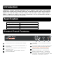
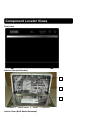
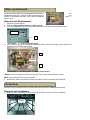
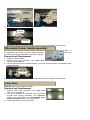
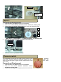
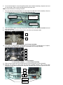
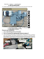
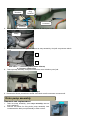
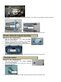
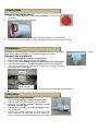
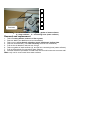
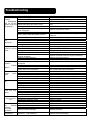
 Technical Service Guide
Compact Dishwasher
MODEL SERIES: WQP6-3206B
IMPORTANT SAFETY NOTICE
The information in this service guide is intended for use by individuals possessing adequate backgrounds of
electrical, electronic, and mechanical experience. Any attempt to repair a major appliance may result in personal
injury and property damage. The manufacturer or seller cannot be responsible for the interpretation of this
information, nor can it assume any liability in connection with its use.
WARNING
To avoid personal injury, disconnect power before servicing this product. If electrical power is required for diagnosis
or test purposes, disconnect the power immediately after performing the necessary checks.
RECONNECT ALL GROUNDING DEVICES
If grounding wires, screws, straps, clips, nuts, or washers used to complete a path to ground are removed for
service, they must be returned to their original position and properly fastened.
MIDEA CONSUMER PRODUCTS
TECHNICAL SERVICE GUIDE
COPYRIGHT. 2003
ALL RIGHTS RESERVED. THIS SERVICE GUIDE MAY NOT BE REPRODUCED IN WHOLE OR IN PART, IN ANY FORM, WITHOUT
WRITTEN PERMISSION FROM THE MIDEA DISHWASHER MANUFACTURING COMPANY.
CONTENTS
Introduction ............................................................................................................................................................. 1 Specification ........................................................................................................................................................... 1 Control Panel Features......................................................................................................................................... 1 Component Locator Views ................................................................................................................................... 1 Dishwasher Components ..................................................................................................................................... 1 Main control board......................................................................................................................................... 1 Outer Door ...................................................................................................................................................... 1 Dispenser ........................................................................................................................................................ 1 Door Handle Assembly ................................................................................................................................. 1 Microswitch (door handle assembly) .......................................................................................................... 1 Inner Door ....................................................................................................................................................... 1 Shell ................................................................................................................................................................. 1 Operating board ............................................................................................................................................. 1 Air Breather Assembly .................................................................................................................................. 1 Siphon ............................................................................................................................................................. 1 Pressure switch.............................................................................................................................................. 1 Tank assembly ............................................................................................................................................... 1 Sump assembly.............................................................................................................................................. 1 Drain pump assembly ................................................................................................................................... 1 Motor pump assembly................................................................................................................................... 1 Heater elements assembly........................................................................................................................... 1 Heater elements support assembly ............................................................................................................ 1 Thermal resistor ............................................................................................................................................. 1 Check plate..................................................................................................................................................... 1 Flowmeter ....................................................................................................................................................... 1 Inlet valve........................................................................................................................................................ 1 Floater assembly............................................................................................................................................ 1 Microswitch (floater assembly) .................................................................................................................... 1 Water softener ................................................................................................................................................ 1 Troubleshooting........................................................................................................................................................ 1 Introduction
WQP6-3201 compact electrical dishwasher with 6 washing cycles offers good washing
performance to satisfy every washing requirement. Its electronic control is easy and convenient to
operate. The rack can hold up to 6 sets of dishes. The size (width * depth * height: 550mm *
500mm * 436mm) can easily fit in any corner of the kitchen, and it’s recommended to locate at
which the water hose connection is accessible.
Specification
Rating voltage:
Heater elements:
Water pressure:
Water temperature:
Capacity:
220~240V / 50Hz
1200W
0.04~1.0MPa
Colder water
6 settings
Control Panel Features
2
8
1
1
P o we r B u tto n: To tu r n o n/ o ff th e p o we r su p p.l y
5
Delay Button
(0 ~24hours )
To press the button to delay time
2
Power Light : To be on when the ON/ OFF Button is
Pressed down.
6
3
Washing Program Selector: To press the button to
select wash cycles.
3in1 function Button: To press the button When
you need no salt and rinse aid but 3in1 tablet.
(Only for program: Intensive/ Normal/ Eco.)
7
4
Start/ Reset Button: Press this button to start or
pause the dishwasher.
Child lock function: To press 3in1 function
button and delay button at the same time.
8
Display: To show delay time, salt warming,
rinse- aid warming, countdown of washing
cycle' s time, program what you selected, child
lock function, 3in1 function and so on.
Component Locator Views
Front View Interior View (with basket) 1
2
3
Part Name: 1 – cutlery basket
2 – basket
Interior View (With Basket Removed) 3 – dispenser
1
2
3
4
5
Part Name: 1 – Nut of air breather 2 – Nut of siphon
4 – Sprayer 5 – Filter System
3 – Cover of softener
Back View 1
Drain Hose
connecter
2
3
Inlet Hose
Connecter
4
Part Name: 1 – Backboard
2 – Hollow plate
3 – Bottom board
4 – Power cord Dishwasher Components
Note: Throughout this manual, features and appearance may vary from your model.
WARNING: Always turn off the electric power supply before servicing any electrical component,
making ohmmeter checks, or replacing any parts.
Note: All voltage checks should be made with a voltmeter having a full scale range of 250 volts
or higher. After service is completed, be sure all safety grounding circuits are complete,
all electrical connections are secure, and all access panels are in place.
Main control board
The main control board controls all electrical elements in
dishwasher machine. It located in the protecting box in
bottom of dishwasher machine. And it easy is replaced
cannot work.
the
the
when it
Removal and Replacement
1. Disconnect power supply.
2. Take off cutlery basket, basket and filter system.
3. Turn the dishwasher machine. And remove all screw for fixing cover of protecting box.
Screw
1
Part Name: 1 – cover of protecting box 4. Pull out all housings and terminals (including some locking terminals), then remove all
screws for fixing main control board.
1
Screws
2
Part name: 1 – protecting box
2 – main control board
Note: mark all housings and terminals’ positions and colors before pulling out them.
Note: some terminals are locking terminals.
5. Reverse the above procedure to install. And check out all connectors connects well.
Outer Door The outer door covers the door to the dishwasher and protects the detergent dispenser.
Removal and Installation
1. Open the door of dishwasher. And remove all screws for fixing outer door assembly.
Screws
2. Hold on outer door assembly. Remove all screws for fixing the operating board.
1
Screws
2
3
Part Name: 1 – outer door
2 – handle cover
3 – operating board
Caution: Inner door of edges are sharp. Some corners and edges of parts are sharp.
3. Remove all screws for fixing handle cover.
Screws
4. Reverse the above procedure to install. And check out all connectors connects well.
Front View (with outer door assembly removed) 1
2
3
4
5
6
7
Part Name: 1 – door handle assembly 2 – microswitch (Door handle assembly)
3 – dispenser 4 –door hinge (right) 5 – Rod for door hinges
6 – door hinge (left) 7 – operating board Dispenser The dispenser automatically dispenses both the
the rinse agent at the appropriate times. The
activated twice during a wash cycle.
detergent
dispenser
and
is
The first time, the dispenser is activated, the lever
slides up the
right-hand path of the connecting rod. This action moves the cover catch and releases the
detergent cover. When deactivated, the lever resets to rest under the notch in the center of the
connecting rod. When activated for the second time in a cycle, the lever lifts the connecting
rod by the notch, lifting the rinse dispenser plunger and releasing the rinse agent. When
deactivated, the lever returns to its original starting position. The magnetic sensor is connected
to rinse aid warning light at control panel by wires. When the indicator lights up, it should add
more rinse aid.
1
4
2
5
3
6
Part Name: 1 – cover catch 2 – detergent power compartment
3 – cover 4 –sight glass
5 – rinse agent cap 6 – detergent tablet compartment 1
3
2
4
5
Part Name: 1 – electromagnetic valve 2 – lever
3 – plunger 4 – connecting rod
5 – magnetic sensor Removal and Replacement
1. Remove outer door assembly. (see outer door removal and installation)
2. Pull out all terminals of dispenser. Then remove all screws for fixing dispenser.
Locking terminals
Screws
1
2
Part Name: 1 – dispenser brackets 2 – dispenser 5. Reverse the above procedure to install. And check out all connectors connects well.
Door Handle Assembly Removal and Replacement
1. Disconnect power supply.
2. Remove outer door assembly. (see outer door
removal and installation)
3. Unfit all snap-fits of outer door assembly for fixing
microswitch (door handle assembly). And pull out
microswitch (door handle assembly).
Note: Don’t pull out all terminals of microswitch (door handle assembly)
4. Remove all screws for fixing door handle assembly.
Screws
Snap-fits
5. Reverse the above procedure to install. And check out all connectors connects well.
Microswitch (door handle assembly)
The microswitch connects a forceful electric power. All
the dishwasher are series connection with microswitch.
microswitch closes, the dishwasher machine is stopped.
loads of
When the
Removal and Replacement
1. Disconnect power supply.
2. Remove outer door assembly. (see outer door
removal and installation)
3. Pull out microswitch (door handle assembly). Then pull out all terminals of microswitch (door
handle assembly)
Terminals
4. Reverse the above procedure to install. And check out all connectors connects well.
Inner Door
Caution: Inner door of edges are sharp.
Removal and Replacement
1. Remove outer door assembly. (see outer door
removal and installation)
2. Pull out all terminals of dispenser and microswitch
(include some locking terminals). (see dispenser
removal and replacement, and microswitch (door
handle assembly) removal and replacement)
3. Remove all screws for fixing inner door.
Screws 4. Remove dispenser. (see dispenser removal and replacement)
5. Remove door handle assembly. (see door handle assembly removal and replacement)
6. Reverse the above procedure to install. And check out all connectors connects well.
Shell
Removal and Installation
1. Take off cutlery basket, basket and filter system.
2. Remove all screws for fixing shell with tank assembly in the front of dishwasher machine.
Screws
3. Remove all screws for fixing shell with backboard and bottom board in the rear of
dishwasher machine.
4. Turn the dishwasher machine. Remove all screws for fixing shell with bottom board in the
bottom of dishwasher machine.
Snap-fits (3)
Snap-fits (1)
Snap-fits (4)
Screws
Screws
Snap-fits (2)
5. Unfix all snap-fits for fixing shell with other
Include two snap-fits of backboard (1),
two snap-fits of washboard (3), and six
snap-fits of bottom board (2), (4) and (5).
Snap-fits (5)
parts.
Tips: If you press edges of shell like
illustrator, you can easy unfix all snap-fits
removing all screws that fix shell with
parts.
6. Reverse the above procedure to install.
And check out all connectors connects
well.
Back View (with shell removed) after
other
1
2
3
4
Part Name: 1 – corner board
2 – absorber
3 – backboard
4 – hollow plate Operating board
Removal and Replacement
1.
2.
3.
4.
Disconnect power supply.
Remove shell. (see shell removal and installation)
Take out two corner boards, absorber sound, backboard, hollow plate.
Remove all screws for fixing cover of protecting box. (see main control board removal and
replacement)
5. Put out all housings for connecting operating board.
6. Then take out connecting lines of operating board from protecting box.
Connecting lines of
operating board
Housings
7. Remove outer door assembly. (See outer door removal and installation).
8. Remove all screws for fixing operating board.
9. Reverse the above procedure to install. And check out all connectors connects well.
Air Breather Assembly
Removal and Replacement
1.
2.
3.
4.
5.
Remove shell. (see shell removal and installation)
Take out two corner boards, absorber sound, backboard, hollow plate.
Contrarotate nut of air breather. Take out air breather gasket.
Take out gasket of air breather, and remove clamp for fixing connecting hose to air breather.
Reverse the above procedure to install.
Clamp
Gasket of air
breather
Siphon
Removal and Replacement
1.
2.
3.
Remove shell. (see shell removal and installation)
Take out two corner boards, absorber sound, backboard, hollow plate.
Contrarotate nut of siphon. Take out one way valve and gasket of siphon.
1
2
3
4.
Part name: 1 – nut of siphon 2 – gasket of siphon 3 – one way valve
Remove two clamps for fixing connecting hoses with siphon.
Clamps
5.
Reverse the above procedure to install.
Pressure switch
As the dishwasher basin fills with water, the air pressure in the
switch hose increases. When the pressure reaches the aim of
switch will act and give a signal to main control board. Then
will be work.
Removal and Replacement
1.
2.
3.
Remove shell. (see shell removal and installation)
Take out two corner boards, absorber sound,
backboard, hollow plate.
Unfix the sheet copper for fixing the pressure switch hose.
pressure
value, the
the drain
1
2
3
4.
Part name: 1 – sheet copper 2 – pressure switch hose
Unfix the snap-fit of bottom board for
fixing pressure switch. And pull out
pressure switch hose. Pull out all
terminals of pressure switch
3 – pressure switch
Snap-fits
of bottom
board
Note: mark all terminals’ colors and
positions.
5.
Locking
terminals
Reverse the above procedure to install.
And check out all connectors connects
well.
Tank assembly
1
2
3
4
5
6
7
Part Name: 1 – tank 2 – door handle assembly 3 – dispenser
4 – rod for door hinges 5 – right front chamber bracket
6 – strengthen muscle 7 – left front chamber bracket Removal and Installation
1.
2.
3.
4.
5.
Take off cutlery basket, basket and filter system.
Remove shell. (see shell removal and installation)
Take out two corner boards, absorber sound, backboard, hollow plate.
Remove all screws for fixing cover of protecting box cover. Put out all housings for
connecting operating board. Take out connecting lines of operating board from protecting
box. (see operating board removal and replacement)
Remove outer door assembly (with operating board). (See outer door removal and
installation).
6.
Put out all terminals for connecting Microswitch (door handle assembly), dispenser and rod
for door hinges. Take out all connecting lines from inner door.
Note: some terminals are locking terminals.
7.
The plug terminal of tank assembly is on the edge in the left side of tank assembly. Remove
the screw and the nut for fixing ring terminals of ground lines.
Plug terminal of
tank assembly
Ring terminals
Screw and nut
8.
9.
Unfix the sheet copper for fixing the pressure switch hose. (see pressure switch removal
and replacement)
Remove two screws for fixing spray holder, then take out the spray holder.
1
2
Screws
Part name: 1 – sprayer holder 2 – nut of sump assembly
10. Turn cover of water softener. Contrarotate nut of air breather. Contrarotate nut of siphon,
then take out one way valve from siphon. Contrarotate nut of sump assembly.
1
2
3
4
Part name: 1 – nut of air breather 2 – nut of siphon
3 – nut of water softener 4 – nut of sump assembly
11. Take out door springs and connecting lines for connecting spring to door assembly.
12. Remove all screws for fixing right and left front chamber bracket. Take out the tank
assembly, at the same time unfix the snap-fits of bottom board for fixing right and left front
chamber bracket.
1
2
3
4
Snap-fits
Screws
Part name: 1 – springs 2 – connecting lines
3 – right front chamber bracket
4 – left front chamber bracket
13. Reverse the above procedure to install. And check out all connectors connects well.
Sump assembly
1
2
3
4
5
6
7
Part Name: 1 – motor pump assembly 2 – thermal resistor
3 – drain pump assembly 4 – sump 5 – check plate holder
6 – heater elements support assembly
7 – heater elements assembly Removal and Installation
1.
2.
3.
4.
5.
Take off cutlery basket, basket and filter system.
Remove shell. (see shell removal and installation)
Take out two corner boards, absorber sound, backboard, hollow plate.
Remove tank assembly. (see tank assembly removal and installation)
Pull out all terminals and housings of sump assembly; include two terminals for connecting
drain pump assembly, three locking terminals and one connector for connecting motor
pump assembly, two terminals for connecting heater elements, two terminals for connecting
heater elements support assembly. And unfix connector of thermal resistor. Remove nut
and take out a tooth lock washer and one ring terminal of heater elements assembly.
Locking terminals
Terminals
Connector
Terminals
Ring
Terminal
Connector
6.
Terminals
Remove one clamp for fixing connecting hose to check plate holder.
Clamp
7.
Pull out hose for connecting water softener to sump assembly. And pull out pressure switch
hose.
1
2
8.
Part name: 1 – connecting hose (water softener)
2 – Pressure switch hose
Take up sump assembly, and pull out that from motor vibration-proof pad.
1
Part name: 1 – motor vibration-proof pad
6. Reverse the above procedure to install. And check out all connectors connects well.
Drain pump assembly
Removal and replacement
1.
2.
Take out sump assembly. (see sump assembly removal
and installation)
Remove all screws for fixing drain pump assembly. And
contrarotate the drain pump assembly to take out that.
3.
Reverse the above procedure to install. And check out all connectors connects well.
Motor pump assembly
Removal and replacement
1.
2.
Take out sump assembly. (see sump assembly removal
and installation)
Remove all screws for fixing sump pump assembly. Screws
3.
4.
Replace a new motor pump assembly.
Reverse the above procedure to install. And check out all connectors connects well.
Heater elements assembly
Removal and replacement
1.
2.
Take out sump assembly. (see sump assembly
removal and installation)
Remove all screws for fixing heater elements
assembly. Take out heater elements assembly and
heater elements support assembly.
Screws
3.
Remove all nuts for fixing heater elements assembly. Then take out two gaskets of heater elements
assembly.
Nuts
Gaskets
4.
Reverse the above procedure to install. And check out all connectors connects well.
Heater elements support assembly
Removal and replacement
1.
2.
3.
Take out sump assembly. (see sump assembly
removal and installation)
Remove heater elements assembly. (see heater
elements assembly removal and replacement)
Take out gasket of heater elements support assembly.
Gasket
4.
Reverse the above procedure to install. And check out all connectors connects well.
Thermal resistor
Removal and replacement
1.
2.
Take out sump assembly. (see sump assembly
removal and installation)
Turn the sump assembly, and remove all screws for
fixing thermal resistor.
Screws
3.
Reverse the above procedure to install. And check out all connectors connects well.
Check plate
Removal and replacement
1.
2.
Take out sump assembly. (see sump assembly removal and
installation)
Pull out check plate holder assembly.
3.
4.
Pull out check plate from check plate holder, and replace a new check plate.
Reverse the above procedure to install. And check out all connectors connects well.
Flowmeter
Flowmeter is an instrument for monitoring, measuring the rate of flow. Main
board control inlet valve to be on / off according signal of flowmeter.
Removal and Installation
1.
2.
3.
4.
5.
Take off cutlery basket, basket and filter system.
Remove shell. (see shell removal and installation)
Take out two corner boards, absorber sound, backboard, hollow plate.
Remove tank assembly. (see tank assembly removal and installation)
Take out plug housing for male terminal. Remove all clamps for fixing
connecting hose to flowmeter.
Clamps
Plug housing
6.
Reverse the above procedure to install. And check out all connectors connects well.
Inlet valve
Removal and Replacement
1.
2.
3.
4.
5.
Take off cutlery basket, basket and filter system.
Remove shell. (see shell removal and installation)
Take out two corner boards, absorber sound,
backboard, hollow plate.
Remove tank assembly. (see tank assembly removal
and installation)
Remove two locking terminals for connecting inlet
valve. Then take out Inlet valve block for inlet valve,
and then take out inlet valve. Remove clamp for fixing connecting hose to inlet valve.
control
1
Clamp
Locking terminals
6.
Part name: 1 – Inlet valve block
Reverse the above procedure to install. And check out all connectors connects well.
Floater assembly
1
2
3
Part name: 1 – floater holder
2 – microswitch (floater assembly)
3 – floater
Removal and Installation
1.
2.
3.
4.
5.
Take off cutlery basket, basket and filter system.
Remove shell. (see shell removal and installation)
Take out two corner boards, absorber sound, backboard, hollow plate.
Remove tank assembly. (see tank assembly removal and installation)
Take up the bottom board; remove two screws for fixing floater assembly.
Screws
6.
7.
Pull out all locking terminals for connecting Microswitch (floater assembly).
Reverse the above procedure to install. And check out all connectors connects well.
Microswitch (floater assembly)
Removal and Replacement
1.
2.
3.
4.
5.
Remove floater assembly. (see floater assembly
removal and installation)
Pull out all locking terminals for connecting
Microswitch (floater assembly).
Remove one screw for fixing Microswitch (floater assembly).
Replace a new Microswitch (floater assembly)
Reverse the above procedure to install. And check out all connectors connects well.
Water softener
Water softener is an instrument for softening hard water in some location.
1
2
3
4
Terminals
5
Part name: 1 – air breather 2 – O ring 3 – gasket of water softener
4 – water softener 5 – connecting hose (water softener)
Removal and replacement
1.
2.
3.
4.
5.
6.
7.
8.
Take off cutlery basket, basket and filter system.
Remove shell. (see shell removal and installation)
Take out two corner boards, absorber sound, backboard, hollow plate.
Remove tank assembly. (see tank assembly removal and installation)
Pull out the air breather, take out two O rings
Take out gasket of water softener (2), and pull out connecting hose (water softener).
Pull out all terminals for connecting water softener.
Reverse the above procedure to install. And check out all connectors connects well.
Note: only use for some model have water softener.
Troubleshooting SYMPTOM
3 in 1 lamp
twinkle
( Dishwasher
will not fill with
water or will not
fill properly.)
CHECK FOR THE FOLLOWING
The water supply is turned off.
Defective water fill valve.
Low water pressure.
Obstructed water fills valve or hose.
Damaged or defective wiring.
Defective pressure switch for high water
level safeguard.
Defective flowmeter.
Heavy water usage elsewhere in home.
Dishwasher will
not
pump out.
Dishwasher
runs but. will not
heat.
Glass
lamp
twinkle
(
overfall
alarm)
Do not work
when
press
start
Too little water
fill.
Dishwasher
runs with door
open.
Motor hums but
will not start or
run.
Motor trips out
on
internal
thermal
overload
protector
Repeated
dishwasher
REMEDY
Turn the water supply on.
Replace the water fill valve.
Minimum water pressure of 20 PSI.
Disassemble and clean the water fill valve and
hose.
Repair the wiring.
Replace the pressure switch.
Replace the flowmeter
Use dishwasher when water usage is at a
minimum.
Replace the PCB assembly
Replace the drain pump.
check the drainhose
Replace the PCB assembly
Repair the wiring.
The lowest input voltage is 198V
Replace the Thermal resistor
Repair the wiring.
See “Too little water fill.”
Defective PCB assembly
Defective drain pump.
Obstructed drainhose
Defective PCB assembly
Damaged or defective wiring.
Low input voltage.
Defective Thermal resistor
Damaged or defective wiring.
Too little water fill.
Defective micro-switch of heater elements
support assembly.
Defective heater element.
Defective PCB assembly
Defective
micro-switch for overfall
safeguard
Damaged or defective wiring.
Defective PCB assembly
Water leaks from dishwasher.
The door not close well
Defective door switch contacts.
Defective door handle assembly.
Damaged or defective wiring.
Defective PCB assembly
Dishwasher not level.
Defective flowmeter.
Clogged filter assembly.
Water siphons out
Defective pressure switch.
Defective door switch contacts.
Defective door handle assembly.
Damaged or defective wiring.
Defective PCB assembly
Defective motor bearings.
Defective motor capacitor.
Damaged or defective wiring.
Improper motor voltage.
Motor windings shorted.
Improper motor voltage.
Defective motor capacitor.
Repair the wiring.
Replace the PCB assembly
See “Water leaks from dishwasher”
close the door
Replace the door switch.
Replace the door handle assembly.
Repair the wiring.
Replace the PCB assembly
Level the dishwasher.
Replace the flowmeter
Clean the filter assembly.
Clean or Replace the One way valve
Replace the pressure switch.
Replace the door switch.
Replace the door handle assembly.
Repair the wiring.
Replace the PCB assembly
Replace the motor.
Replace the motor capacitor.
Repair the wiring.
Replace the motor.
Replace the motor.
Replace the motor.
Replace the motor capacitor.
Defective motor bearings.
Replace the motor.
Defective
Replace the PCB assembly
PCB assembly
Replace the heater elements support assembly.
Replace the heater element.
Replace the PCB assembly
Replace the micro-switch
cycles.
Water remains
in bottom
Spotting or
filming on
glasses
(reposition of
food soil).
Noisy pump
assembly.
A small amount of water (in sump area) is
normal.
This is necessary to keep the pump primed and is
drained automatically at the beginning of each
cycle.
Defective drain pump
Replace the drain pump.
Defective Check plate
Defective One way valve
Detergent allowed to stand too long in the
dispenser or excessive amounts of
detergent are being used.
Clean or Replace the Check plate
Clean or Replace the One way valve
Improper loading of dishes, pots,
pans, and nesting of silverware.
Debris in bottom of tub sump area.
Pump parts were not properly installed.
Impellers are not properly shimmed or are
rubbing.
Poor
washability.
Poor drying of
dishes
Clogged filter assembly.
Dishware stop the sprayer
Improper loading of dishes, pots, pans,
and nesting of silverware.
Little detergent/rinse module
Select improper program
Defective detergent/rinse module
Defective spray arm.
Too little water fill.
Defective motor pump
Improper loading of dishes, pots, pans,
and nesting of silverware.
Select improper
Water leaks
from
dishwasher.
program
Instruct the customer on proper use of dishwasher
detergent. Refer to the
owner’s manual.
Clean out the sump area.
Inspect the pump and correct and installation
errors.
Use the shim guage furnished in the impeller seal
kit. When the seal is properly shimmed the
impellers will be in the correct operating position.
Clean the filter assembly.
revolve the sprayer before wash.
Refer to the owners manual.
Replace the etergent/rinse module.
Check spray arm for proper rotation.
See “Too little water fill” symptom.
Replace the motor pump
Instruct the customer on proper loading of the
dishwasher. Refer to the owners manual.
Defective dispenser
Too much water fill.
Defective tub seal.
Defective softener gasket.
Defective drain pump
Dishwasher not level.
Replace the dispenser
See previous symptom.
Replace the tub seal.
Replace softener gasket.
Replace the drain pump
Level the dishwasher.
Soap suds leak from dishwasher.
Loose hose clamps.
Loose heater element.
Defective sump seals.
Motor and drain pump assembly not
seated properly with sump.
Defective Heater elements support
assembly seals.
Refer to use and care manual.
Tighten or replace hose clamps.
Tighten heater element mounting nuts.
Replace the sump seals.
Remount the motor and drain pump assembly.
Remount Heater elements support assembly.